
10A31-4 - Electronic board Daytronic - Free user manual and instructions
Find the device manual for free 10A31-4 Daytronic in PDF.


| Product Type | Signal Conditioner / Amplifier |
| Model | 10A31-4 |
| Brand | Daytronic |
| Dimensions (H x W x D) | 180 mm x 120 mm x 50 mm |
| Weight | 0.5 kg |
| Power Supply | 100-240 V AC, 50/60 Hz |
| Power Consumption | 10 VA max |
| Number of Channels | 4 |
| Input Signal Type | Voltage, Current, Thermocouple, RTD |
| Output Signal Type | 0-10 V, 4-20 mA, RS-232 |
| Bandwidth | DC to 10 kHz |
| Accuracy | ±0.1% of reading |
| Operating Temperature | 0°C to 50°C |
| Storage Temperature | -20°C to 70°C |
| Humidity Range | 0% to 95% non-condensing |
| Protection Class | IP20 |
| Enclosure Material | Aluminum, steel |
| Maintenance | Clean with dry cloth; no user-serviceable parts inside |
| Safety Features | Overvoltage protection, short-circuit protection |
| Repairability | Replaceable fuse, accessible terminals |
| Included Accessories | Power cord, user manual |
| Compliance | CE, RoHS |
Frequently Asked Questions - 10A31-4 Daytronic
User questions about 10A31-4 Daytronic
0 question about this device. Answer the ones you know or ask your own.
Ask a new question about this device
Download the instructions for your Electronic board in PDF format for free! Find your manual 10A31-4 - Daytronic and take your electronic device back in hand. On this page are published all the documents necessary for the use of your device. 10A31-4 by Daytronic.
USER MANUAL 10A31-4 Daytronic
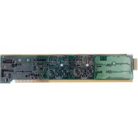
The Model 10A31-4 is for measurement of displacement, force, pressure, and other parameters obtained with a variable reluctance transducer or linear variable differential transformer (LVDT). Based on the synchronous carrier-demodulator principle, it supplies regulated, remotely sensed AC excitation for four independent transducer channels. It then demodulates, filters, and amplifies the resulting signals to produce system outputs precisely proportional to LVDT core displacement. The 10A31-4 automatically adjusts to the signal phase shift of the transducer in use, thereby insuring optimum sensitivity and linearity. Special input provisions exist for “long-stroke” LVDT's (full-scale range of ±1 inch or greater).
For each of its four analog inputs, the 10A31-4 produces two displayable outputs: one with "normal" analog filtering and one with high bandwidth characteristics (see Specifications and Table 1, below). All four channels share a common sensed excitation of 100 mA (rms), maximum. As explained in Section 2, for cables over 25 feet in length, this limits the distance from the sense point to the transducer to about 20 feet of 18-gage wire.
The 10A31-4's eight SUBCHANNELS are assigned as follows:
Table 1 Model 10A31-4 Subchannels
Subchannel No. Function
| 1 | Input No. 1, low-bandwidth filter |
| 2 | Input No. 2, low-bandwidth filter |
| 3 | Input No. 3, low-bandwidth filter |
| 4 | Input No. 4, low-bandwidth filter |
| 5 | Input No. 1, high-bandwidth filter |
| 6 | Input No. 2, high-bandwidth filter |
| 7 | Input No. 3, high-bandwidth filter |
| 8 | Input No. 4, high-bandwidth filter |
ADDITIONAL 10A31-4 SPECIFICATIONS
Transducer Types: 5- or 7-wire LVDT's capable of 3280-Hz operation and having primary impedance of 80 ohms or greater (all Daytronic LVDT transducers are suitable); 3- or 5-wire variable reluctance transducers
Sensitivity Range: Accommodates full-scale ranges from ±0.010 in. ( ±0.25 mm) to ±6.0 in. ( ±15.24 cm), when used with Daytronic or equivalent transducers; for System 10 channel “type” codes assigned to 10A31-4 data channels, see Table 2, below
Standard Input (rms, full-scale): 78, 156, or 312 mV/V
Long-Stroke Input (rms, full-scale): 525 mV/V, 1.05 V/V, or 2.10 V/V
(cont'd)
Excitation (per channel): Nominal 3.0 V-AC (rms) at 3280 Hz; 40 mA (rms), maximum
Amplifier (per channel):
Common-Mode Range: ±5 V operating; ±12 V without instrument damage
Common-Mode Rejection Ratio: DC and at 60 Hz: infinite; at 3 kHz: -60 dB
Input Impedance: Differential: 400 kΩ; Common-Mode: 100 kΩ
Offset: Initial: ±3% of full scale; vs. Temperature: ±20 ppm/°C; vs. Time: ±0.01% f.s./month
Gain Accuracy: ±0.02% of full scale typical, following calibration*
Gain Stability: vs. Temperature: ±50 ppm/°C; vs. Time: ±20 ppm/month
Filter (per channel):
NORMAL: 3-pole modified Butterworth; 3 dB down at 6 Hz; 60 dB down at 60 Hz
Step-Response Settling Time (Full-Scale Output):
To 1% of final value: 250 msec
To 0.1% of final value: 400 msec
To 0.02% of final value: 500 msec
HIGH BANDWIDTH: 3-pole modified Butterworth; 3 dB down at 200 Hz; 60 dB down at 2750 Hz
Step-Response Settling Time (Full-Scale Output):
To 1% of final value: 5 msec
To 0.1% of final value: 8 msec
To 0.02% of final value: 13 msec
Auxiliary Outputs: Filtered outputs available on mainframe wire-wrap pins
Table 2 10A31-4 "Type" Codes
Full-Scale Channel Input (RMS) Type Code
78 mV/V 64
156 mV/V 63
312 mV/V 65**
525 mV/V 64
1.05 V/V 63
2.10 V/V 65**
2 TRANSDUCER CONNECTIONS
The Model 10A31-4's I/O CONNECTOR mates with Daytronic CONDITIONER CONNECTOR No. 60322, shown in Fig. 1.5 (in Manual Section 1.E.1). Table 3 gives standard pin assignments for the I/O Connector. With regard to 10A31-4 cabling, please note the following:
a. All four 10A31-4 input channels use a single, sensed excitation supply.
b. 5-wire LVDT cabling (Fig. 1(a)) or 3-wire variable reluctance transducer cabling (Fig. 1(c)) is to be used when the cable is under 20 feet in length. In this case, the +SENSE and -SENSE lines are tied to the corresponding EXCITATION lines at the CONDITIONER CONNECTOR.
7-wire LVDT cabling (Fig. 1(b)) or 5-wire variable reluctance transducer cabling (Fig. 1(d)) is to be used when the cable is 20 feet or longer. In this case, the +SENSE and -SENSE lines are tied to the corresponding EXCITATION lines at the transducer. NOTE: It is important that the distance "D" from each transducer to its sensing points be as short as possible (at least under 20 feet when 18-gage wire is used).
c. For each LVDT transducer connected to the 10A31-4, you should connect the "center wire" that joins both series-opposed secondary coils to the CABLE SHIELD at the transducer end, instead of bringing this line through a cable shield to the conditioner connector (as shown in Figs. 1(a) and 1(b)).
d. Note that there are special +SIGNAL and -SIGNAL connections for use with LONG-STROKE LVDT's (full-scale range of ±1 inch or greater). Thus, to allow for the larger input voltages produced by such a sensor, you would connect its +SIGNAL line to Pin 2, 4, 6, or 8 (instead of to Pin 1, 3, 5, or 7, respectively). Similarly, you would connect the -SIGNAL line to Pin B, D, F, or J (instead of to Pin A, C, E, or H, respectively).
e. When wiring a variable reluctance transducer to the 10A31-4, you must install a 10-kilohm "half-bridge completion" resistor between the -SIGNAL pin (A, C, E, or H) and each of the two SENSE lines, as shown in Figs. 1(c) and 1(d).
Table 3 Model 10A31-4 Pin Assignments
| I/O Connector Conditioner Conditioner Pin Channel Line Number Number Function | ||
| 1 | 1 | +SIGNAL |
| A | 1 | -SIGNAL |
| 2 | 1 | +SIGNAL (LONG-STROKE) |
| B | 1 | -SIGNAL (LONG-STROKE) |
| 3 | 2 | +SIGNAL |
| C | 2 | -SIGNAL |
| 4 | 2 | +SIGNAL (LONG-STROKE) |
| D | 2 | -SIGNAL (LONG-STROKE) |
| 5 | 3 | +SIGNAL |
| E | 3 | -SIGNAL |
| 6 | 3 | +SIGNAL (LONG-STROKE) |
| F | 3 | -SIGNAL (LONG-STROKE) |
| 7 | 4 | +SIGNAL |
| H | 4 | -SIGNAL |
| 8 | 4 | +SIGNAL (LONG-STROKE) |
| J | 4 | -SIGNAL (LONG-STROKE) |
| 9 | * | +EXCITATION |
| K | * | -EXCITATION |
| 10 | * | +SENSE |
| L | * | -SENSE |
* This function is common to all four channels.
Fig. 1 Model 10A31-4 Transducer Cabling

flowchart
graph TD
    A["Channel 1"] --> B["+ EXCITATION"]
    B --> C["Channel 2"]
    C --> D["+ EXCITATION"]
    D --> E["Channel 3"]
    E --> F["+ EXCITATION"]
    F --> G["Channel 4"]
    G --> H["SHIELD"]
    H --> I[""Long-Stroke" LVDT Input"]

    subgraph Channel 1
        J["PRi"] --> K["SEC 1"]
        L["SEC 2"] --> M["SIGNAL COMMON"]
        N["SEC 2"] --> O["SIGNAL"]
    end

    subgraph Channel 2
        P["PRi"] --> Q["SEC 1"]
        R["SEC 2"] --> S["SIGNAL COMMON"]
        T["SEC 2"] --> U["SIGNAL"]
    end

    subgraph Channel 3
        V["PRi"] --> W["SEC 1"]
        X["SEC 2"] --> Y["SIGNAL COMMON"]
        Z["SEC 2"] --> AA["SIGNAL"]
    end

    subgraph Channel 4
        AB["PRi"] --> AC["SEC 1"]
        AD["SEC 2"] --> AE["SIGNAL COMMON"]
        AF["SEC 2"] --> AG["SIGNAL"]
    end

    subgraph Conditioner Connector (No. 60322)
        AH["SHIELD"] --> AI["L-S Inp* 1"]
        AI --> AJ["B 2"]
        AJ --> AK["L-S Inp* 3"]
        AK --> AL["C 3"]
        AL --> AM["D 4"]
        AM --> AN["E 5"]
        AN --> AO["F 6"]
        AO --> AP["H 7"]
        AP --> AQ["J 8"]
        AQ --> AR["K 9"]
        AR --> AS["L 10 +SENSE"]
        AS --> AT["-SENSE"]
    end

    subgraph Figure_1(a) 5-Wire LVDT Cabling (under 20 ft. in length)
        AU["Connector pins shown as viewed from rear (cable), side of connector"] --> AV["Ground Lug"]
        AW["*Long-Stroke" LVDT Input"] --> AX["SHIELD"]
    end

flowchart
graph TD
A["Channel 1"] --> B["+ Excitation"]
B --> C["Channel 2"]
C --> D["+ Excitation"]
D --> E["Channel 3"]
E --> F["+ Excitation"]
F --> G["Channel 4"]
subgraph Channel 1
H["PRi"] --> I["SEC 1 + SIGNAL"]
J["PRi"] --> K["SEC 2 - SIGNAL"]
end
subgraph Channel 2
L["PRi"] --> M["SEC 1 + SIGNAL"]
N["PRi"] --> O["SEC 2 - SIGNAL"]
end
subgraph Channel 3
P["PRi"] --> Q["SEC 1 + SIGNAL"]
R["PRi"] --> S["SEC 2 - SIGNAL"]
end
subgraph Channel 4
T["PRi"] --> U["SEC 1 + SIGNAL"]
V["PRi"] --> W["SEC 2 - SIGNAL"]
end
I --> X["Sensing Points"]
K --> X
M --> X
Q --> X
U --> X
U --> X
Y["SHEILD Connector pins shown as viewed from rear (cable) side of connector"] --> Z[""Long-Stroke" LVDT Input<br>SHIELD Connector pins shown as viewed from rear (cable) side of connector"]
style Channel 1 fill:#f9f,stroke:#333
style Channel 2 fill:#f9f,stroke:#333
style Channel 3 fill:#f9f,stroke:#333
style Channel 4 fill:#f9f,stroke:#333
subgraph Channel 1
X
Y
Z
AA
AB
AC
AD
AE
AF
AG
AH
AI
AJ
AK
AL
AM
AN
AO
AP
AQ
AR
AS
AT
AU
AV
AW
AX
AY
AZ
BA
BB
BC
BD
BE
BF
BG
BH
BI
BJ
BK
BL
BM
BN
BO
BP
BPB
BPB
BPB
BPB
BPB
BPB
end
subgraph Channel 2
X
Y
Z
AA
AB
AC
AD
AE
AF
AG
AH
AI
AJ
AK
AL
ALB
end
subgraph Channel 3
X
Y
Z
AA
AB
AC
AD
AE
AF
AG
AH
AI
AJ
AJB
end
subgraph Channel 4
X
Y
Z
AA
AB
AC
AD
AE
AF
AG
AH
AI
AJB
end
note right of Channel 3: Sensing Points
10A31-4 QUAD LVDT CARD


3 SETUP AND/OR OPERATING CONSIDERATIONS
3.a CONFIGURATION AND CALIBRATION
For initial configuration of ANALOG INPUT CHANNELS dedicated to a specific Model 10A31-4 card when used in System 10, see the general remarks on System 10 "real-channel" configuration in Manual Section 1.G.1 and elsewhere in the System 10 Guidebook. For 10A31-4 channel "type" codes, see Table 2, above.
In System 10, a relatively linear Model 10A31-4 channel normally employs TWO-POINT (DEADWEIGHT) CALIBRATION.* See Manual Section 1.G.5 for a general discussion of this conventional "zero and span" calibration technique. Note, however, the following special procedure that applies to an LVDT-based Channel No. "x":
- Make sure the channel has been properly "typed" and "located" (see Manual Section 1.G.1).
- Turn ON the system EEPROM SWITCH and enter a command of
$$ \text { BEE } x = 0 [ \mathrm{CR} ] $$
This command sets an initial ZERO OFFSET ("b" term) of zero for Channel No. x.
-
Observing a "live" reading of the channel, mechanically adjust the fixture and physical position of the LVDT until the lowest reading occurs. This is the LVDT's "electrical null" point.
-
With the transducer still in "null" position, enter a command of
$$ Z R O \times [ C R ] $$
-
Displace the LVDT probe by a precisely known distance, preferably between 80% and 100% of the transducer's nominal full-scale rating.
-
Command
$$ F R C x = z [ C R ] $$
where “z” is the exact value of the displacement produced in Step 5, expressed in appropriate engineering units (the precision of the final measurement will match that of the entered “z” value).
- Repeat Steps 4, 5, and 6, if necessary, until the LVDT's zero and span points coincide with the calibration block or micrometer reference being used.



Brand : Daytronic
Model : 10A31-4
Category : Electronic board