
DRN-16 - Uncategorized CROWN - Free user manual and instructions
Find the device manual for free DRN-16 CROWN in PDF.

| Product Type | Digital Recorder |
| Brand | Crown |
| Model | DRN-16 |
| Dimensions | 200 x 150 x 50 mm |
| Weight | 0.5 kg |
| Power Supply | 5V DC via USB-C |
| Battery | Built-in rechargeable lithium-ion, 2000 mAh |
| Recording Format | WAV, MP3 up to 48 kHz/24-bit |
| Storage | MicroSD card slot (up to 32 GB) |
| Microphone | Built-in stereo electret condenser |
| Speaker | Built-in 1W mono speaker |
| Functions | Record, playback, pause, skip, voice activation, low-cut filter |
| Display | 1.44-inch color TFT LCD |
| Connectivity | USB-C for data transfer and charging, 3.5 mm headphone jack |
| Maintenance | Clean with a soft dry cloth; avoid liquids |
| Safety | Do not expose to extreme temperatures or moisture; use only approved charger |
| Spare Parts | Available through Crown service centers: battery, USB cable, carrying case |
| Repairability | Repairable by authorized technicians; user removable microSD card |
| General Information | Designed for high-quality portable recordings; user manual and firmware updates available at crown-audio.com |
Frequently Asked Questions - DRN-16 CROWN
User questions about DRN-16 CROWN
0 question about this device. Answer the ones you know or ask your own.
Ask a new question about this device
Download the instructions for your Uncategorized in PDF format for free! Find your manual DRN-16 - CROWN and take your electronic device back in hand. On this page are published all the documents necessary for the use of your device. DRN-16 by CROWN.
USER MANUAL DRN-16 CROWN
The Drone is a general purpose IQ command and control module. It accepts a variety of types of external stimuli and converts them into commands for various other IQ components in the system. It is a modular unit designed for mounting in the IQ-CAG Card Cage. It operates on a nominal +12 VDC, and includes 30 day battery backup. It is equipped to communicate directly with a computer via female DB9 serial port (RS232/RS422). As a system interface it supports two Crown Bus serial data loops. It is programmed via graphic objects or text oriented screens in the IQ-MSD Turbo 1.2 (or higher) program.
IQ-CAG Card Cage Installation
The Drone designed for easy installation into the IQ Card Cage. The IQ-CAG is a four rack space cage which is segregated into 14 1.25 inch widths. The Drone is three widths (3.75 inches wide). The IQ-LPS +12 VDC Linear Power Supply is another Card Cage unit, and provides power supply voltage for Card Cage components, including the Drone. If an IQ-LPS is not used, another suitable supply such as an adaptor or battery is required. Components designed to mount in the IQ-CAG are modular in construction. They slide into the cage on rails, and are held in place by small screws. At the rear of the cage a terminal board ("T-board") is used to provide connection to external input and output devices. The T-board for the Drone is shown on the following page.
Front Panel
The front panel for the Drone is shown to the left. A DSPI indicator lights up to indicate that digital information addressed to that unit is being received. It also has a power indicator showing that the unit is powered by +12 VDC.
A. Baud Switches
SW1 on the Drone module is a four position DIP switch used to set the RS232/422 baud rate. The Drone supports from 1200 to 38400 baud. Note: Some PCs do not support greater than 9600 baud.
B. IQ Address Switches
Drones, like all IQ System components, must have a valid IQ Address in order to communicate a computer or other system components. A valid address is an address ranging from 1 to 250, with no other Drones having the same IQ Address in the same system.
C. Battery Backup
The battery on the Drone allows it to maintain its programming for up to 30 days after
IQ-DRN16 DRONE
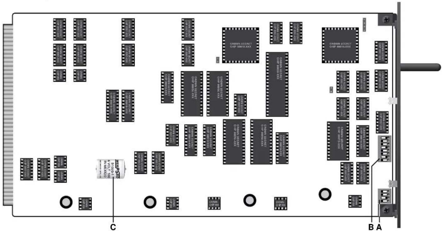
DRONE MODULE CIRCUIT BOARD
power is lost. It is soldered to the board for stability. It is automatically charges whenever the Drone is powered.
D. Power Supply Connectors
Plated holes are provided for connection of +12 VDC and ground from an IQ-LPS or other nominal 12 volt supply. Holes are sized to accept 8-32 screws.
E. Computer Communication
The Drone has a female DB9 serial port for communication with a computer via RS232 or RS422. The Drone has been specially designed to automatically sense and adjust for either of these communication standards. Since RS232 is standard on PCs, the Drone is designed to accept commonly available Radio Shack 26-117 RS232 cables.
F. Crown Bus Communication
The Drone supports two Crown Bus serial data loops for control of up to 250 of each type of IQ component per loop. The Crown Bus is a communication standard for carrying IQ command protocol. It normally operates on a 20 ma current loop, which the Drone supports. Using external tranceivers, fiber optic cable can also be used for long distance Crown Bus loops.
G. +10V Source
The Drone provides +10 VDC for use by external devices such as potentiometers. The reason for this is to support the use of external pots for adjusting voltage to the voltage sensing analog inputs.
H. Unbalanced Analog Inputs
Of the Drone's 16 analog inputs, 12 are unbalanced (analog inputs 5 through 16). These inputs sense an analog DC or AC voltage from zero to the Drone input sensitivity. Input sensitivity is factory set at +10 VDC (7.07 VAC RMS, or +19.2 dBu). An analog input may be a DC voltage sensed via linear potentiometer, or may be an AC or audio signal.
I. Gain Set Resistors
R1 through R20 are installed gain and sensitivity resistors for the analog inputs (balanced and unbalanced). These resistor fix the sensitivity of the analog inputs. They may be changed to modify input sensitivity up or down. They also affect gain from balanced analog inputs to their respective analog outputs.
J. Balanced Analog Inputs
Analog inputs numbered 1 through 4 are balanced. The reason for balanced inputs is to accept balanced audio from sources such as a microphone, as well as accept a linear voltage sensed from an external potentiometer. Phantom power (10V) is available by modifying the Drone T-board.
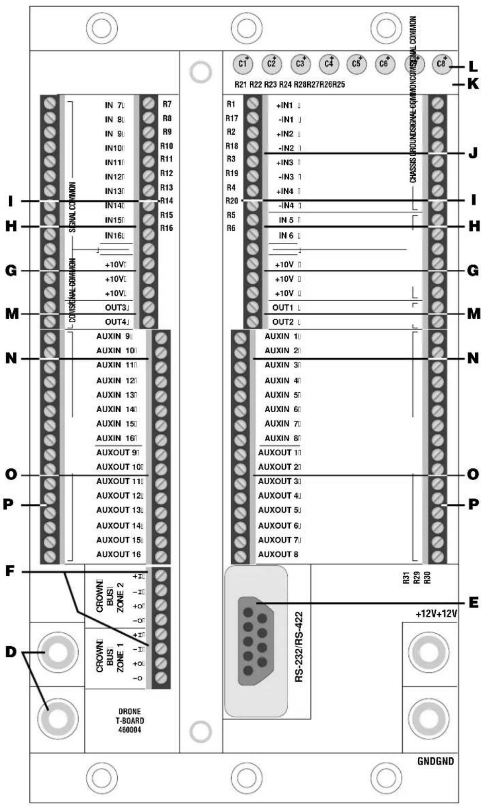
Drone "T-Board" For External Connections
K. Phantom Power Resistors
To provide phantom power to the balanced analog inputs for condenser microphones involves add two 2 Kohm resistors per input. The Drone T-board comes from the factory with these resistors not installed.
L. Phantom Power Coupling Caps
A second modification to each balanced analog input is required in order to provide phantom power. Isolation capacitors are shorted for DC coupling, but to AC couple and provide phantom the short may be removed by
clipping leads on the back of the terminal board.
M. Analog Outputs
Four unbalanced analog outputs are provided. The output is taken from the corresponding balanced inputs. The Drone provides 3.6 dB of gain from balanced input to unbalanced output with the standard factory gain set resistors installed.
N. Digital (Aux) Inputs
The Drone has 16 digital (Aux) inputs. These inputs sense a logical high (on) or low (off) condition. The Drone has two modes of operation to handle the logic information sensed at these inputs. The first is referred to as "simplex." In simplex mode, the individual input is directly associated with a specific group of whatever logical system commands you associate with it. The second mode is called "binary." In the binary mode three or more consecutive digital inputs are grouped together. The group functions like a parallel port, looking for a binary number on the inputs (lowest input number is the LSB). A command set group is associated with each binary number. The maximum number of combinations, hence maximum number of unique command groups, depends on how many digital inputs are grouped together in a binary channel. The last member of a binary channel is a strobe. For example, if you want a 16 bit input, you need four consecutive digital inputs in binary mode with a fifth input as a strobe. When a binary number from 0 to 15 is sensed, send a logical high to the strobe and the Drone will engage whatever system commands are associated with the binary number you provided.
O. Digital (Aux) Outputs
In addition to 16 logic inputs, the Drone also has 16 logical outputs. These outputs can drive a logical input or other device when switched on. The Drone can be programmed to provide a logical output based on almost any type information provided by the Drone or other system component. Output drive is a maximum of +15V at 15 ma.
P. Ground Strips
A series of ground strips are provided for plenty of ground reference connections to external devices such as pots, relays, LEDs, or other devices.
Transponder Mode
To use multiple Drones in a system requires that each Drone operate with Transponder Mode on. In this mode each Drone may only directly control components connected to its own Loop 2 Crown Bus. Drones are interconnected using the Loop 1 connection on each Drone. In software the loop interconnecting the Drones becomes Loop 251 and the local loop on each individual Drone takes a loop number which is the same as that Drone's address. This mode of operation allows a system to have up to 251 loops (one master Drone loop and a transponder loop per Drone with a maximum of 250 Drones). Note: Turbo 1.3 or higher is required to support Drone V1.1 firmware with Transponder Mode capability.
Training The Drone
There are two main ways to program a Drone. Both require IQ-MSD Turbo 1.2 (or higher) software for IBM compatible PCs. The Drone, like the SMX-6™ Mixer, has sub-block screens where analog and digital input commands are programmed. Turbo software also has special objects for the Drone that allow you to program the Drone using simple screen objects and a mouse. Once programmed, the computer may remain if desired, or may be completely removed for total stand alone automatic operation.
Drone Intelligence (Version 1.1)
As of November 1995 Drone V1.11 is available, replacing the original V1.0 firmware. The new firmware supports all function and features of the first version with several valuable additions. The Drone now supports operation as an interface for U-Code products such as the Crown PIP-DP, White Instruments 5000 Series IQ DSP products, and t.c. electronics EQ for IQ. The new Drone firmware also supports multiple Drone system architecture with Transponder Mode. Other operational areas are also improved including expansion of paralyze capabilities.
The Drone has another function as yet not discussed, called the paralyze command. The paralyze command allows a digital input (simplex mode only) to paralyze other inputs on demand. This level of operation allows one input to lock out another for security or other purposes.
For additional information about the Drone, including information about the next firmware release, contact the Crown Technical Support Group at 1-800-342-6939/1-219-294-8200.
Additional Electrical Specifications
Dimensions: 3.75 inches (9.52 cm) wide for 3-space IQ-CAG mounting; 7 inches (17.78 cm) high, and 12.125 inches (30.8 cm) behind mounting surface.
Power Supply: +10 to +15 VDC, +12VDC nominal. Internal battery soldered to the module provides backup for power loss up to 30 days; charges when Drone is powered. Internally the Drone produces several voltages including +15 VDC for digital output drive, and +10 VDC for use by external control devices. Display: Power LED shows presence of +12 VDC supply, DSPI LED shows reception of digital information addressed to the unit.
Controls: An 8 segment DIP switch on the component face of the circuit board is used to set the IQ Address. A 4 segment DIP switch sets the RS232/422 baud rate. Jumpers on the module face are factory set to configure memory. Resistors and capacitors mounted on the T-board are used to set analog input gain and phantom power.
Serial Port: A female DB9 serial port is provided to accept either RS232 or RS422 for direct communication with a computer. Radio Shack 26-117 standard RS232 cable is recommended for PCs.
Crown Bus: Two Crown Bus serial data loops can be used via an 8 pin mini-barrier strip.
Analog Inputs: 16 analog inputs are provided which can accept DC, AC, or audio for system control and command functions. Inputs 1 through 4 are balanced. Phantom power is optional, sensitivity is changeable. Inputs 5 through 16 are unbalanced, sensitivity is changeable. Sensitivity is factory set to 10 VDC/7.07 VAC/+19.2 dBu. Frequency response of all inputs is DC to 20 kHz (+0/-1 dB); with phantom enabled 16 to 20 kHz (+0/-3 dB). Common mode rejection better than -40 dB (balanced inputs). Input impedance is 69 Kohms.
Phantom Power: +10V, requires installation of resistors and clipping out electrical shorts across input coupling capacitors.
Analog Outputs: Four unbalanced AC coupled outputs are provided, numbers correspond to balanced analog inputs. Gain factory set to +3.6 dB ±0.5 dB. Frequency response 20 to 20 kHz (+0/-1 dB). Maximum drive is +18 dBm into 600 ohms. Less than 0.15% THD at full output through the frequency range.
Digital Inputs: 16 digital inputs for direct simplex or binary input to logic command sets. +2.5V to +15V is a digital high; -10V to +0.8V is a digital low. Output impedance 220 Kohms from 0V to +5V input; 20 Kohm above or below this range.
Digital Outputs: 16 digital outputs are provided for driving external device. Output when on is +15V at 15 ma (1 Kohm output impedance).
Finish: Smooth black powder coat.
Guaranteed Excellence
CROWN
Crown International, Inc.
PO Box 1000 Elkhart, IN 46515-1000
Ph. 800-342-6939/219-294-8200
Fax. 219-294-8301
Trademark Notice:
MRX-12, ^TM MRX-24, ^TM and SMX-6 ^TM are trademarks, and Crown ^ and IQ System ^ are registered trademarks of Crown International Inc.
- IQ-CAG Card Cage Installation
- Front Panel
- Baud Switches
- IQ Address Switches
- Battery Backup
- Power Supply Connectors
- Computer Communication
- Crown Bus Communication
- +10V Source
- Unbalanced Analog Inputs
- Gain Set Resistors
- Balanced Analog Inputs
- Phantom Power Resistors
- Phantom Power Coupling Caps
- Analog Outputs
- Digital (Aux) Inputs
- Digital (Aux) Outputs
- Ground Strips
- Transponder Mode
- Training The Drone
- Drone Intelligence (Version 1.1)
- Additional Electrical Specifications
- Guaranteed Excellence
- CROWN
- Trademark Notice:
Brand : CROWN
Model : DRN-16
Category : Uncategorized