ASA1222EL - Access Control System Dahua Technology - Free user manual and instructions
Find the device manual for free ASA1222EL Dahua Technology in PDF.

| Product Type | Access Control System |
| Brand | Dahua Technology |
| Model | ASA1222EL |
| Dimensions | 150 x 80 x 30 mm |
| Weight | 0.5 kg |
| Power Supply | 12V DC, 1A |
| Communication | TCP/IP, RS485 |
| Card Types | EM, Mifare |
| User Capacity | 10,000 users |
| Event Capacity | 100,000 events |
| Operating Temperature | -20°C to 60°C |
| Humidity | 10% to 90% non-condensing |
| Enclosure | Metal, IP65 |
| Display | 2.8-inch TFT |
| Keypad | 12 keys |
| Reader | Built-in |
| Functions | Access control, time attendance, alarm |
| Mounting | Wall mount |
| Certification | CE, FCC |
| Spare Parts | Power adapter, mounting bracket |
| Maintenance | Clean with dry cloth, avoid water |
| Safety | Built-in tamper switch, anti-passback |
| Warranty | 2 years |
Frequently Asked Questions - ASA1222EL Dahua Technology
User questions about ASA1222EL Dahua Technology
0 question about this device. Answer the ones you know or ask your own.
Ask a new question about this device
Download the instructions for your Access Control System in PDF format for free! Find your manual ASA1222EL - Dahua Technology and take your electronic device back in hand. On this page are published all the documents necessary for the use of your device. ASA1222EL by Dahua Technology.
USER MANUAL ASA1222EL Dahua Technology
Attendance Standalone
User's Manual

natural_image
Abstract geometric composition with gray and blue color blocks (no text or symbols)Foreword
General
This manual introduces the functions and operations of the Attendance Standalone (hereinafter referred to as the "Device"). Read carefully before using the device, and keep the manual safe for future reference.
Safety Instructions
The following signal words might appear in the manual.
| Signal Words Meaning | ||
 | DANGER | Indicates a high potential hazard which, if not avoided, will result in death or serious injury. |
 | WARNING | Indicates a medium or low potential hazard which, if not avoided, could result in slight or moderate injury. |
 | CAUTION | Indicates a potential risk which, if not avoided, could result in property damage, data loss, reductions in performance, or unpredictable results. |
 | TIPS | Provides methods to help you solve a problem or save time. |
 | NOTE | Provides additional information as a supplement to the text. |
Revision History
| Version | Revision Content | Release Time |
| V1.0.0 | First Release. | December 2022 |
Privacy Protection Notice
As the device user or data controller, you might collect the personal data of others such as their face, fingerprints, and license plate number. You need to be in compliance with your local privacy protection laws and regulations to protect the legitimate rights and interests of other people by implementing measures which include but are not limited: Providing clear and visible identification to inform people of the existence of the surveillance area and provide required contact information.
About the Manual
- The manual is for reference only. Slight differences might be found between the manual and the product.
- We are not liable for losses incurred due to operating the product in ways that are not in compliance with the manual.
- The manual will be updated according to the latest laws and regulations of related jurisdictions. For detailed information, see the paper user's manual, use our CD-ROM, scan the QR code or visit our official website. The manual is for reference only. Slight differences might be found between the electronic version and the paper version.
- All designs and software are subject to change without prior written notice. Product updates might result in some differences appearing between the actual product and the manual. Please contact customer service for the latest program and supplementary documentation.
- There might be errors in the print or deviations in the description of the functions, operations and technical data. If there is any doubt or dispute, we reserve the right of final explanation.
- Upgrade the reader software or try other mainstream reader software if the manual (in PDF format) cannot be opened.
- All trademarks, registered trademarks and company names in the manual are properties of their respective owners.
- Please visit our website, contact the supplier or customer service if any problems occur while using the device.
- If there is any uncertainty or controversy, we reserve the right of final explanation.
Important Safeguards and Warnings
This section introduces content covering the proper handling of the Device, hazard prevention, and prevention of property damage. Read carefully before using the Device, and comply with the guidelines when using it.
Transportation Requirement

Transport, use and store the Device under allowed humidity and temperature conditions.
Storage Requirement

Store the Device under allowed humidity and temperature conditions.
Installation Requirements

WARNING
- Do not connect the power adapter to the Device while the adapter is powered on.
- Strictly comply with the local electric safety code and standards. Make sure the ambient voltage is stable and meets the power supply requirements of the Device.
- Do not connect the Device to two or more kinds of power supplies, to avoid damage to the Device.
- Improper use of the battery might result in a fire or explosion.

- Personnel working at heights must take all necessary measures to ensure personal safety including wearing a helmet and safety belts.
- Do not place the Device in a place exposed to sunlight or near heat sources.
- Keep the Device away from dampness, dust, and soot.
• Install the Device on a stable surface to prevent it from falling. - Install the Device in a well-ventilated place, and do not block its ventilation.
- Use an adapter or cabinet power supply provided by the manufacturer.
- Use the power cords that are recommended for the region and conform to the rated power specifications.
- The power supply must conform to the requirements of ES1 in IEC 62368-1 standard and be no higher than PS2. Please note that the power supply requirements are subject to the Device label.
- The Device is a class I electrical appliance. Make sure that the power supply of the Device is connected to a power socket with protective earthing.
Operation Requirements

- Check whether the power supply is correct before use.
- Do not unplug the power cord on the side of the Device while the adapter is powered on.
- Operate the Device within the rated range of power input and output.
- Use the Device under allowed humidity and temperature conditions.
- Do not drop or splash liquid onto the Device, and make sure that there is no object filled with
liquid on the Device to prevent liquid from flowing into it.
- Do not disassemble the Device without professional instruction.
- This product is professional equipment.
- This equipment is not suitable for use in locations where children are likely to be present.
Table of Contents
Foreword....
Important Safeguards and Warnings....III
1 Product Overview....1
2 Local Operations ...... 2
2.1 Keypad Introduction....2
2.2 Powering On....5
2.3 Creating Administrator Account....5
2.4 Logging In....5
2.5 User Management 6
2.5.1 Add New Users 6
2.5.1.1 Adding One by One....6
2.5.1.2 Adding in Batches....8
2.5.2 Viewing User Information ...... 9
2.5.3 Adding Departments 9
2.6 Attendance Logs Management ....10
2.6.1 Searching for Attendance Records ...... 10
2.6.2 Exporting Attendance Log 11
2.7 Configuring the Attendance Time....11
2.7.1 Configuring Shifts ...... 11
2.7.2 Configuring Schedules....12
2.7.3 Configuring Late-in and Early-out Time....14
2.8 USB Management....14
2.8.1 Importing/Exporting User Information 14
2.8.2 Importing/Exporting User Fingerprint 15
2.8.3 Importing/Exporting Bell Information 15
2.8.4 Importing/Exporting Auto Switch Time 15
2.9 Configuring Time....15
2.10 Configuring Network Communication....16
2.11 Configuring Features....17
2.11.1 Configuring Bell Time....17
2.11.2 Configuring Recheck Interval ...... 18
2.11.3 Configuring Attendance Method....18
2.11.4 Configuring the System Automatic Test ....19
2.11.5 Configuring the Attendance Event Mode....19
2.11.6 Configuring State Switch Time....20
2.12 Configuring the System....20
2.13 Viewing the System Information ....21
2.14 Checking Attendance....21
2.15 Attendance Rules 21
2.16 Working Hours Calculation....22
3 SmartPSS Lite Operations....23
3.1 Installation......23
3.2 Initialization....23
3.3 Logging In....24
3.4 Adding Devices 25
3.5 Department Management ......26
3.6 Adding Staff 27
3.6.1 Adding Staff One by One Manually ....27
3.6.2 Adding Staff in Batches ....31
3.7 Permission Configuration ....33
3.7.1 Adding Permission Group ....33
3.7.2 Assigning Permissions .... 34
3.8 Adding Attendance Period....35
3.9 Adding Attendance Shift....39
Appendix 1 Important Points of Fingerprint Registration Instructions ....41
Appendix 2 Input Method....43
Appendix 3 FAQ....44
Appendix 4 Cybersecurity Recommendations....45
1 Product Overview
The Device can be used to track attendance of people. People can clock in/out through fingerprint, password, and card. Card swiping is only available on select models.
2 Local Operations
The keypad is slightly different depending on the models of the Device. This section uses the GL model as an example.
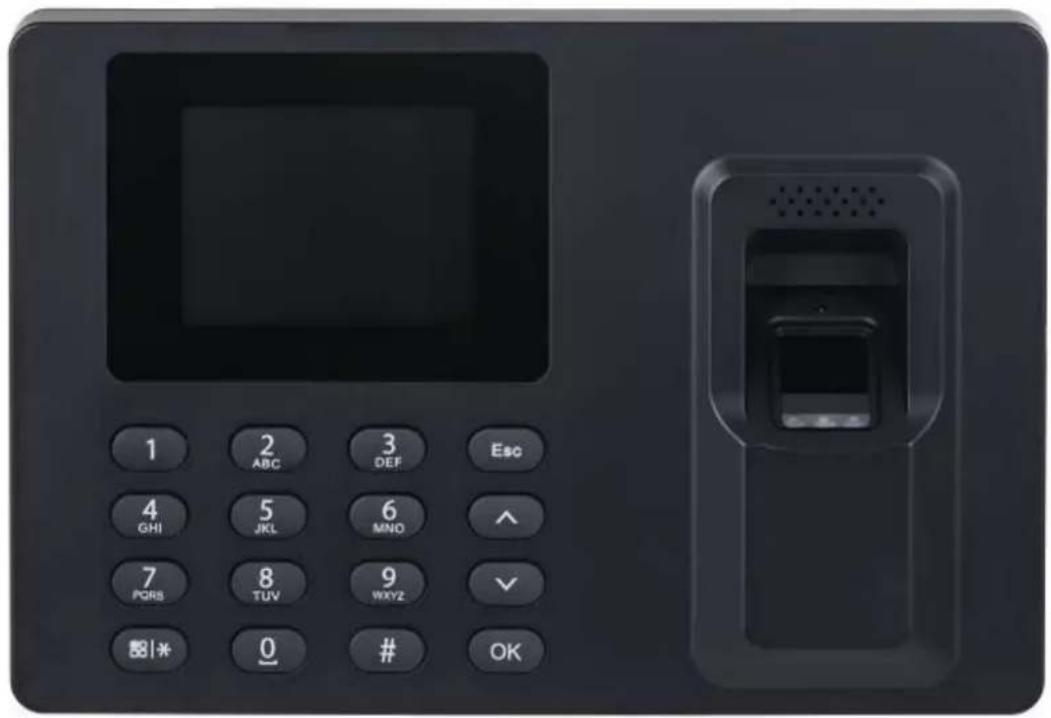
2.1 Keypad Introduction
Figure 2-1 Appearance (GL)

text_image
1 2 ABC 3 DEF Esc / F1 4 GHI 5 JKL 6 MNO ^ / F2 7 PQRS 8 TUV 9 WXYZ ✓ / F3 58 | * | 0 0 # OK / F4Table 2-1 Parameters description
| Parameter Description | |
| 0–9 Number keys to input numbers and letters. | |
| ESC/F1 | ● Exit or go to the previous screen.● Tap it on the standby screen to clock in. |
| ^/F2 | ● Tap it on the standby screen, BREAK OUT will be displayed on the screen.● Tap to go up the options. |
| v/F3 | ● Tap it on the standby screen, and BREAK IN will be displayed on the screen.● Tap it to go down through the options. |
| OK/F4 | ● Confirm your settings.● On the standby screen, tap it to clock out. |
| # | ● Delete.● Shortcut for reviewing records. |
| Press and hold it for over 3 seconds to turn the Device off/on.On the standby screen, tap it to enter the main menu by fingerprints, passwords or cards.[17WW]Only administrators can enter the main menu.Tap it to change the input types (numbers, letters and symbols). | |
Figure 2-2 Appearance (Model E)

text_image
1 2 ABC 3 DEF Esc 4 GHI 5 JKL 6 MNO ^ 7 PORS 8 TUV 9 WXYZ ✓ 图1* 0 # OKFigure 2-3 Appearance (Model E-S)
text_image
1 2 ABC 3 DEF Esc 4 GHI 5 JKL 6 MNO ^ 7 PCR8 8 TUV 9 WXYZ ✓ 88|* 0 # OKTable 2-2 Parameters description
| Parameter | Description |
| 0~9 | Number key to input numbers and letters. |
| ESC Go back or exit. | |
| ^ | Tap it to go up the options. |
| ∨ | Tap it to go down through the options. |
| OK Enter or confirm | |
| # Backspace | |
| Enter the main menu or switch input method. | |
2.2 Powering On
After the Device is powered on, the standby screen is displayed.
Figure 2-4 Standby screen
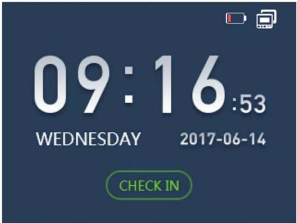
text_image
09:16:53 WEDNESDAY 2017-06-14 CHECK IN• indicates that the network is disconnected.
• Indicates that the network is connected.
- indicates the battery status. When the Device starts for the first time, the battery level is 25% (can last for about 1 hour).
2.3 Creating Administrator Account
When the Device is started for the first time, anyone can enter the main menu and configure the Device. For the account security, we recommend you create the administrator account first, and then only administrators can enter the main menu.
Procedure
Step 1 Tap ☐ to enter the main menu screen.
Step 2 Select 1 User > Add New User
Step 3 Enter the user information.
Step 4 Select Administrator from User Level.
- Select User Level, and then tap OK/F4.
- Select ∧/F2 or ∨/F3 to select Administrator.
- Tap OK/F4.
2.4 Logging In
After the admin account is created, you can enter the main menu after you have verified your
identifications through fingerprint, password or card.

The card swiping function is only available on select models.
Figure 2-5 Main Menu
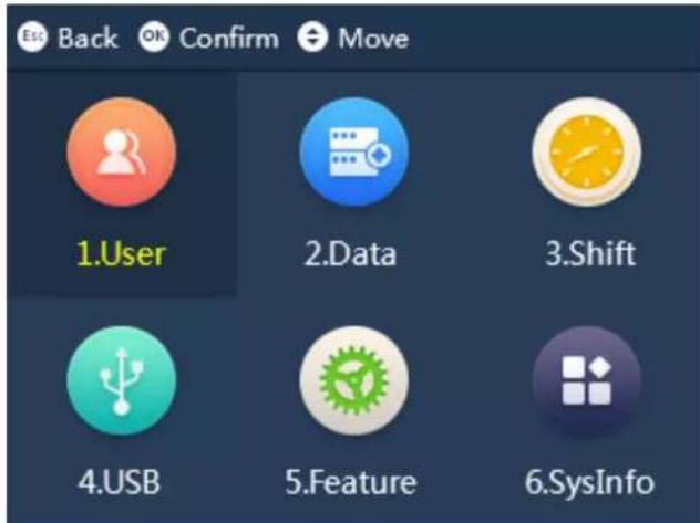
text_image
Back OK Confirm Move 1.User 2.Data 3.Shift 4.USB 5.Feature 6.SysInfoTap 語|*|, and then enter the main menu after your identity has been verified.
- Place your finger on the fingerprint sensor.
- Enter the administrator's ID and password.
- Swipe the card on the card reader.
2.5 User Management
On the main menu, select 1 User, and then you can add new users.
2.5.1 Add New Users
Add users to the Device.
2.5.1.1 Adding One by One
Procedure
Step 1 On the main menu, select 1 User > Add New User.
Figure 2-6 Adding new user
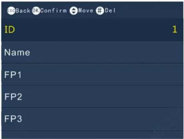
text_image
Esc Back OK Confirm Move # Del ID 1 Name FP1 FP2 FP3
text_image
scBack OK Confirm Move # Del PWD Card Dept Headquarters Schedule Mode Department User Level UserStep 2 Enter the user information.
Table 2-3 Parameters description
| Parameter Description | |
| User ID | Maximum user ID length is 8 digits (the user ID length range can be 1–99999999). |
| Name | Maximum user name length is 16 letters. |
| FP | Register fingerprints. A user can register up to 3 fingerprints. |
| Card | A user can register five cards at most. Swipe your card, and then the card information will be read by the Device. Card function is only available on select models. |
| PWD | Enter the user password. The maximum length of the password is 8 digits.0 alone cannot be set as password and cannot be the first number of a password. |
| Dept. Set departments. | |
| Schedule Mode | Department: Configure department schedules.Personal: Configure personal schedules.. |
| User Level | User: General users can only check their attendance.Administrator: Administrator account can check attendance and enter the main menu. |
2.5.1.2 Adding in Batches
Adding through cards

Adding users through cards is only available on select models.
- On the main menu, select 1 User > Add Cards in Batch.
Figure 2-7 Adding users through cards

text_image
EscBack OK Confirm ID 2 Card- Swipe cards on the card reader.
User ID and card number will be automatically read by the Device.
- Enter the user names, add fingerprints and passwords separately.
Adding through USB
Excel charts with special format are stored in the USB. Export the excel chart first, and then enter user information (including user ID, user name, password, card number, department, user level and schedule mode) into the charts, and then import the charts to the Device. User information with the same User ID will be overwritten.
- On the main menu, select 4 USB > Import User Info.
- Select Confirm-OK.
The user information will be imported.
2.5.2 Viewing User Information
Procedure
Step 1 On the main menu, select 1 User > Query & Edit User.
Step 2 Press OK/F4.
Figure 2-8 Query & edit users

text_image
Esc Back OK Confirm ← Move # Del * Search ID Name Auth. Method 1 JakcStep 3 Tap ∧ /F2or v /F3 to select a user.
Step 4 Tap OK/F4.
Information on the user is displayed.
Step 5 (Optional) Tap OK/4 to edit the information of the user.
2.5.3 Adding Departments
Procedure
Step 1 On the main menu, select 1 User > Edit Dept.
Step 2 Tap OK/F4.
Figure 2-9 Edit department
| Dept.ID | Dept. |
| 01 | HQ |
| 02 | PM1 |
| 03 | PM2 |
| 04 | |
| 05 |
Step 3 Tap ∧/F2 or ∨/F3 to select a department ID, and then Tap OK/F4.
Step 4 Enter the name of the department, and then tap OK/F4.

- The Device supports 20 departments, and they cannot be deleted.
- Department names cannot be empty.
2.6 Attendance Logs Management
2.6.1 Searching for Attendance Records
Procedure
Step 1 On the main menu, select 2 Data > Query User ATT. Record, and then tap OK/F4.
Step 2 Enter the User ID.
The user name is displayed automatically.
Figure 2-10 Enter user ID
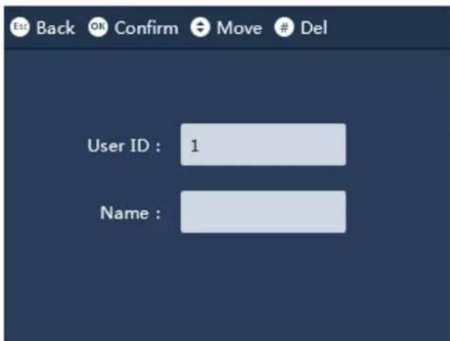
text_image
Est Back OK Confirm Move # Del User ID : 1 Name :Step 3 Tap OK/F4.
The attendance log of the user is displayed.
2.6.2 Exporting Attendance Log
Before you export attendance record, make sure the USB is inserted. During exporting, do not remove the USB or operate the Device, otherwise the exporting will fail and system malfunction will occur.
Procedure
Step 1 On the main menu, select 2 Data, and then select Export Monthly ATT. Record or Export Monthly ATT. Report, and then tap OK/F4.
Step 2 Select the date, and then tap OK/F4
Step 3 Tap.
The log is exported.
2.7 Configuring the Attendance Time
2.7.1 Configuring Shifts
Configure shifts to define time attendance rules. Employee need to come to work at the scheduled shift start time, and leave at the scheduled shift end time except when they work overtime. You can set up to 24 shifts.
Procedure
Step 1 On the main menu, select 3 Shift >Shift Setup >Shift.
Step 2 Select the number of the shift, and then tap OK/F4.
Step 3 Configure the parameters of the shift.
Figure 2-11 Shift setting

text_image
Est Back OK Confirm Move # Del Shift NO DutyT1 1 08 : 30 - 12 : 00 2 DutyT2 3 13 : 30 - 17 : 00 4 Overtime Session 5 20 : 00 - 21 : 00 6Table 2-4 Shift parameters description
| Parameter Description | |
| Duty T1 | Set the time attendance periods. If you set 08:00 —17:00, you |
| Duty T2 | need to clock in before 08:00 or earlier, and punch out at 17:00 or later, otherwise the abnormal attendance is abnormal.If you clock in for more than once, the earliest punch-in is effective; if you clock out for more than once, the latest punch-out is effective.You can set 2 periods at the same time, the 2 periods cannot overlap. People must clock in and clock out in the both defined periods, and make sure their attendance is normal. |
| Overtime Session | People who clock in/out in the defined overtime period works beyond normal working hours. |
Related Operations
- Export Shift: When the shifts are configured, you can export the shift settings to other Devices through the USB.

The exported file is name after "Import&export_00001". The number indicates the number of the Device.
- Import Shift: Before you import shifts, make sure the USB is inserted to the Device. To avoid failure or system malfunction, do not remove the USB or operate the Device during importing.

Make sure the number of the file name is same to the number of the Device that you will be import to.
2.7.2 Configuring Schedules
A work schedule generally refers to the days per month and the hours per day that an employee is expected to be at their job. You can create different types of work schedules based on different individuals or departments, and then employees must follow the established work schedules.
Procedure
Step 1 On the main menu, select Shift > Schedule Setup > Users Schedule, and then tap OK/F4. Step 2 Set works schedules for individuals.
- Select User Schedule, and then tap OK/F4.
- Enter the ID of an existing user.
The user name and department is displayed automatically. - Tap OK/F4.
- On the calendar, select a date, and then tap OK/F4.
Figure 2-12 User schedule
| User:1 2017/6 schedules | ||||||
| Sun | Mon | Tue | Wed | Thu | Fri | Sat |
| 1 1 | 2 1 | 3 | ||||
| 4 | 5 1 | 6 1 | 7 1 | 8 1 | 9 1 | 10 |
| 11 | 12 1 | 13 1 | 14 1 | 15 1 | 16 1 | 17 |
| 18 | 19 1 | 20 1 | 21 1 | 22 1 | 23 1 | 24 |
| 25 | 26 1 | 27 1 | 28 1 | 29 1 | 30 1 | |
-
Tap ∧/F2 or ∨/F3 to select the schedule, and then tap OK/F4.
-
0 indicates break.
- 1 to 24 indicates the number of the pre-defined shifts. For how to configure shifts, see "2.7.1 Configuring Shifts".
• 25 indicates the business trip.
• 26 indicates the leave of absence.
Step 3 Set works schedules for the department.
- Select Department, and then tap OK/F4.
- Select a department, and then tap OK/F4.
- On the calendar, select a date, and then tap OK/F4.
-
Tap ∧/F2 or ∨/F3 to select the schedule, and then tap OK/F4.
-
0 indicates break.
- 1 to 24 indicates the number of the pre-defined shifts. For how to configure shifts, For how to configure shifts, see "2.7.1 Configuring Shifts".
• 25 indicates the business trip.
• 26 indicates the leave of absence.
Figure 2-13 Department schedule
text_image
Est Back OK Confirm Move # Del Dept:Product schedules Sun Mon Tue Wed Thu Fri Sat 1 1 1 1 1Related Operations
- Export Schedule: When the schedules are configured, you can export the schedules settings to other Devices through the USB.

The exported file is name after "Import&export_00001". The number means indicates the number of the Device.
- Import Schedule: Before you import schedules, make sure the USB is inserted to the Device. To avoid failure or system malfunction, do not remove the USB or operate the Device during importing.

Make sure the number of the file name is same to the number of the Device that you will be import to.
2.7.3 Configuring Late-in and Early-out Time
The late-in and early-out allowed time is used mainly to give the employee a little flexibility to come a little late or leave a little early from work. For example, if the normal punch-in time is 8:00, and the late-in allowed time is set to 5 minutes, the employee who arrives at 8:06 AM will be marked late by 1 minute. If the normal punch-out time is 17:30, and the early-out allowed time is 5 minute, the employee who clock out at 17:25 will be not be considered as an early leave.
Procedure
Step 1 On the main menu, select Shift, and then tap OK/F4.
Step 2 Tap Late Time Setup or Early Leave Time Setup, and then tap OK/F4.
Step 3 Tap ∧/F2 or ∨/F3 to set the time, and then tap OK/F4.
2.8 USB Management
Only supports the types of USB as below.
Table 2-5 Applicable USB models
| Brand Model | |
| Sandisk CZ600 32 GB | |
| BanQ | P8 16 GBP9 8 GBP9 16 GB |
| Aigo U350 64 GB | |
| Hewlett Packard V220W 16 GB | |
2.8.1 Importing/Exporting User Information
Excel charts with special format are stored in the USB. You can enter user information (including user ID, user name, password, card number, department, user level and shifts) into the charts, and then import/export the charts to/from the Device.
Procedure
Step 1 On the main menu, select 4 USB, and then tap OK/F4.
Step 2 Select Import User Info or Export User Info, and then tap OK/F4.
Step 3 Import or export the user information.
The existing user information with the same user ID will be overwritten if you export user information to the Device.
2.8.2 Importing/Exporting User Fingerprint
Procedure
Step 1 On the main menu, select 4 USB, and then tap OK/F4.
Step 2 Select Import User FP or Export User FP, and then tap OK/F4.
Step 3 Import or export the user fingerprint.
The existing user information will be overwritten if you export user information to the Device.
2.8.3 Importing/Exporting Bell Information
Bell information can be imported to and exported from the Device. The bell will ring during the defined period.
Procedure
Step 1 On the main menu, select 4 USB, and then tap OK/F4.
Step 2 Select Import Bell Info or Export Bell Info, and then tap OK/F4.
Step 3 Import or export the bell information.
The existing user information will be overwritten if you export user information to the Device.
2.8.4 Importing/Exporting Auto Switch Time
Auto switch time can be imported and exported to/from the Device. Check in, Break out, Break in, Check out, OT-In, and OT-Out will be displayed on the screen during the defined period.
Procedure
Step 1 On the main menu, select 4 USB, and then tap OK/F4.
Step 2 Select Import Auto Switch Time or Export Auto Switch Time, and then tap OK/F4.
Step 3 Import or export the bell information.
If the existing user information will be overwritten if you export user information to the Device.
2.9 Configuring Time
Procedure
Step 1 On the main menu, select 5 Features > Date & Time, and then tap OK/F4.
Step 2 Configure the date.
Table 2-6 Description of time parameters
| Parameter Description | |
| Date Format | Select a date format.Y stands for the year. M stands for the month. D stands for the day. |
| Date Setup | Set up the date and the time for the Device. The date and time will be displayed on the standby screen. |
| Time Setup | |
| Time Zone | Set time zone for the Device. The time zone range is GMT-12:00 to GMT+13:00. |
| DST | 1. Tap DST, and then tap OK/F4.2. Tap OK/F4 to turn on the DST function.3. Select By Date or By Week from the DST mode list.4. Enter start time and end time, and then tap OK/F4. |
| NTP SetupThis function is only available on select models. | A network time protocol (NTP) server is a machine dedicated as the time sync server for all client computers. If your computer is set to sync with a time server on the network, your clock will show the same time as the server. When the administrator changes the time (for daylight savings), all client machines on the network will also update.1. Tap NTP Setup, and then tap OK/F4.2. Tap OK/F4 to turn on the NTP function.3. Configure the parameters.IP: Enter the IP address of the NTP server, and the Device will automatically sync time with NTP server.Port: Enter the port of the NTP server.Update Period(min): Enter the time synchronization interval. |
2.10 Configuring Network Communication
Configure the network communication of the Device. This function is only available on select models.
Procedure
Step 1 On the main menu, select 5 Features > Communication, and then tap OK/F4.
Step 2 Configure the parameters.
Figure 2-14 Communication

text_image
esc Back OK Confirm ← Move IP 1 13 Mask 255.255.0.0 Gateway 17 .1 Mac Port 37777Table 2-7 Communication Parameters
| Parameter Description | |
| IP It is 192.168.1.108 by default. | |
| Mask | It is 255.255.255.0 by default. |
| Gateway | It is 192.168.1.1 by default. |
| MAC | MAC address of the Device, and it cannot be changed. |
| Port Port number of the Device. |
2.11 Configuring Features
Select 5 Feature > Features, and then you can set state switch time, bell time, recheck interval, verification method, system auto test, attendance event mode, fixed mode setup, and open door keep time.
2.11.1 Configuring Bell Time
Configure the time when the bell rings as a reminder.
Procedure
Step 1 On the main menu, select 5 Features > Features, and then tap OK/F4.
Step 2 Select Bell Time, and then tap OK/F4.
Step 3 Configure the time when the bell rings.
Figure 2-15 Bell time
| Back OK Confirm | |||
| Time | Cycle | Duration(s) | |
| 1 | 00:00 | Every Day | 00 |
| 2 | 00:00 | Every Day | 00 |
| 3 | 00:00 | Every Day | 00 |
| 4 | 00:00 | Every Day | 00 |
| 5 | 00:00 | Every Day | 00 |
Table 2-8 Parameters description
| Parameter Description | |
| Time | The time when the bell rings. |
| Cycle | The bell rings in a cycle. For example, if you set cycle to Monday, the bell rings every Monday. |
| Duration The ring duration. |
2.11.2 Configuring Recheck Interval
Recheck interval is used to set the interval in which you can get your attendance checked. For example, if the interval is set to 3, and you clock in/out for more than once in 3 minutes, the Device will prompt repeat clock in/out.
Procedure
Step 1 On the main menu, select 5 Features > Features, and then tap OK/F4.
Step 2 Select Recheck Interval, and then tap OK/F4.
Step 3 Enter the number or tap ∧/F2 or ∨/F3 to select the time.
The time interval only supports 0, 1, 2, 3, 4, 5, 6, 7, 8, and 9.
2.11.3 Configuring Attendance Method
Set attendance methods, and people can clock in/out by using fingerprint and password and or card.
Procedure
Step 1 On the main menu, select 5 Features > Features, and then tap OK/F4.
Step 2 Select Verification Method, and then tap OK/F4.
Step 3 Tap ∧/F2 orv/F3 to select the attendance method, and then tap OK/F4.
- FP: clock in/out through fingerprint.
- PWD: clock in/out through password.
- Card: clock in/out by swiping card.

Card swiping function is only available on select models.
- FP or PWD or Card: clock in/out through fingerprint or password or card.
- FP or PWD: clock in/out through fingerprint or password.

FP or PWD is only available on select models.
2.11.4 Configuring the System Automatic Test
Run the self-test of the system to make sure the Device can work properly.
Procedure
Step 1 On the main menu, select 5 Features > Features, and then tap OK/F4.
Step 2 Select System self check, and then tap OK/F4.
Step 3 Tap ∧/F2 or ∨/F3 to select a self-check item, and then tap OK/F4.
Table 2-9 Self-test
| Parameter Description | |
| Auto self-check | The system automatically perform the self-test of fingerprint enrollment, display, voice, keypad, USB in sequence. |
| FP self-check | Place you finger on the sensor to check whether the fingerprint is displayed on the screen. |
| Display self-check | The screen displays red, green and blue in sequence. |
| Voice self-check | The Device gives voice prompt. |
| Key self-check | Tap the button to check whether the keypad functions well. |
| USB self-check | Insert a USB to the Device to check whether the Device can recognize the USB. |
2.11.5 Configuring the Attendance Event Mode
When you clock in or clock out, you can set the attendance modes to define the time attendance status.
Procedure
Step 1 On the main menu, select 5 Features > Features, and then tap OK/F4.
Step 2 Select Att. Event Mode, and then tap OK/F4.
Step 3 Tap ∧/F2 or ∨/F3 to select attendance mode, and then tap OK/F4.
Table 2-10 Attendance mode
| Parameter Description | |
| Auto/Manual Mode | After you clock in/out, the screen displays the time attendance status automatically, and you can manually change the attendance status. |
| Forced Mode | After you clock in/out, tap Attendance status to manually select the attendance status. |
| Fixed Mode | Select an attendance status for Fixed Mode Setup, and the screen will displays the pre-defined attendance status all the time when you punch in/out. |
| Keep Door Open for (sec) | The door is held open for a defined time (0 s–600 s.) after you successfully clock in/out. This function is only available on select models. This function is only available on select models. |
2.11.6 Configuring State Switch Time
If you have set manual/auto attendance mode, you can set the state switch time to define the attendance status during different time periods. You can configure up to 24 state switch time.
Prerequisites
The attendance mode was set to Auto/Manual. For details, see "2.11.5 Configuring the Attendance Event Mode".
Procedure
Step 1 On the main menu, select 5 Features > Features, and then tap OK/F4.
Step 2 Select State Switch Time, and then configure the time and state.
Figure 2-16 State switch time
| Est Back OK Confirm Move # Del | ||
| NO. | Time | State |
| 1 | 08:00 | Check In |
| 2 | 17:30 | Check Out |
| 3 | 00:00 | NULL |
| 4 | 00:00 | NULL |
| 5 | 00:00 | NULL |
| 6 | 00:00 | NULL |
Result
For example, if you set the time to 08:00 and the state to Check In for No 1, and set the time to 17:30 and the state to Check Out for No.2, it means from 08:00 to 17:30, the Device automatically displays Check In when you clock in, and you can also manually change your attendance status.
2.12 Configuring the System
Procedure
Step 1 On the main menu, select 5 Features > System, and then tap OK/F4.
Step 2 Configure the system parameters.
2.13 Viewing the System Information
On the main menu, select 6 SysInfo, and then tap OK/F4, you can the information on the system.
Table 2-12 Parameters description
| Parameters Description | |
| Admin Level Management | View or change the user information of administrator account. |
| Management | Enter the ID of the user, and then tap OK/F4, and then you can view the operation logs of administrator. |
| Registration Info | The storage capacity of the Device, such as users, fingerprints, and more. |
| Device Info | View the information of the Device, such as the version, ID, and more. |
| Open Source Software Notice | View the open source software notice of the Device. |
2.14 Checking Attendance
Check attendance through password, fingerprint, or card.
- Attendance through password:
-
On the standby screen, enter the User ID on the keypad, and tap OK/F4.
-
Enter the password, and then tap OK/F4.
-
Attendance through fingerprint: On the standby screen, place your finger on the sensor of the scanner.
- Attendance through card: On the standby screen, swipe the card on the card reader area.

Card swiping function is only available on select models.
2.15 Attendance Rules
This section uses the configured shifts below as an example.
Table 2-13 Shifts (example)
| Shifts Time | |
| Period 1 9:00–12:00 | |
| Period 2 14:00–17:30 | |
| Overtime Session 18:45–20:00 | |
| late-in allowed time | 5 minutes |
| early-out allowed time | 5 minutes |

For details on how to configure shifts, see "2.7.1 Configuring Shifts".
Clock In/Out Time
If 2 time periods are configured, the middle point of the interval is the division of the 2 time periods.
- If the interval of 2 periods is an even number, for example, period 1 is 9:00–12:00, and period 2 is 14:00–17:30, the interval between the 2 periods is 120 minutes, the allowed punch-out time for period 1 is 12:00–12:59, and the allowed punch-in time for period 2 is 13:00–14:00.
- If the interval of 2 periods is an odd number, for example, the period 2 is 14:00–17:30 and the over-time period is 18:45–20:00, the interval is 75. The allowed punch-out time is 17:30–18:07, and the allowed punch-in time of the overtime period is 18:08–18:45.

- If you clock in for multiple times during the allowed punch-in time, the earliest punch-in is effective.
- If you clock out for multiple times during the allowed punch-out time, the last time punch-out is effective.
- There is no late-in or early-out status in the overtime period. The time between the punch-in and punch-out is the overtime.
Table 2-14 Normal Attendance
| Period | Normal Punch-in Time | Normal Punch-out Time |
| Period 1 | 00:00–9:05The attendance time is precise to seconds. For example, 9:05:000–9:05:59 is the normal punch-in time. | 11:55–12:59 |
| Period 2 | 13:00–13:05 | 17:25–18:07 |
Abnormal Attendance
One time period indicates 0.5 day. Each period requires both punch-in and punch-out record, otherwise 0.5 day absence is recorded.
According to Table 2-14, if a person checks the attendance at 9:05, 11:54, and 17:00, it be marked as an early leave by 1 minute in the first period, and 0.5 day absence from work because there is no punch-out in the second period.
2.16 Working Hours Calculation
Actual Working Hours
The total working hours of a day = The working hours of period 1 + The working hours of period 2. For example, the period 1 is 9:00–12:00 and the period 2 is 14:00–17:30, and the normal working hours for a day is 6.5 hours. If a person checks the attendance at 8:00, 12:30, 15:00 and 17:00, the working hours are 3 hours in the period 1, and the working hours are 2 hours in the period 2, and the total working hours are 5 hours.

The working hours are precise down to one decimal place.
Overtime Working Hours
The total overtime = Punch-in time in the overtime period — Punch-out time in the overtime period For example, if a person punches in at 18:20 and punches out at 19:30 during the overtime period, the total overtime working hours are 1.1 hours.
3 SmartPSS Lite Operations
Only certain models support configurations on SmartPSS Lite. For details, see the user's manual of SmartPSS Lite.
3.1 Installation
Contact technical support or download ToolBox to get SmartPSS Lite.
- If you get the software package of SmartPSS Lite, install and run the software according to page instructions.
- If you get the software by the ToolBox, run SmartPSS Lite according to the instructions on the page.
3.2 Initialization
Initialize SmartPSS Lite when you log in for the first time. You will need to set a password for login and your security questions for resetting the password.
Procedure
Step 1 Double-click SmartPSSLite.exe, or click Open next to the software icon in the ToolBox. Step 2 Select the language from the drop-down list, select I have read and agree the software agreement, and then click Next.
Step 3 Click Browse to select the installation path, and then click Install.
Step 4 Click Finish to complete the installation.

Select Run SmartPSSLite to start SmartPSS Lite.
Step 5 Select the application scenes you want to add, and then click OK.
Figure 3-1 Select application scenes
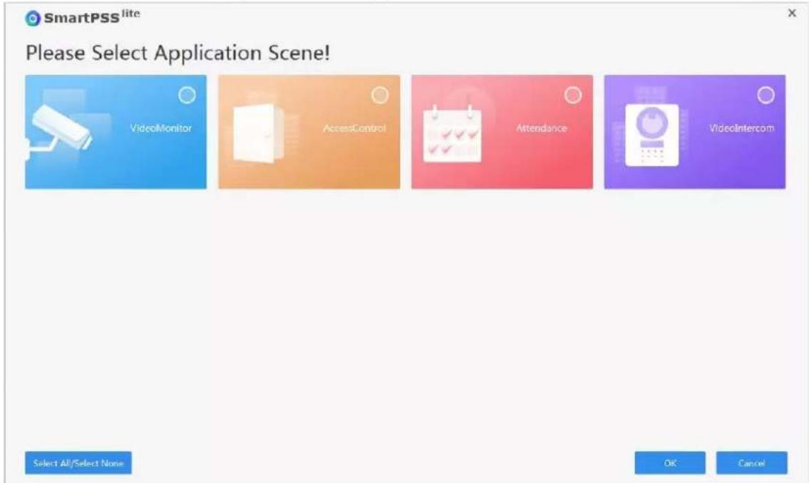
text_image
SmartPSS lite Please Select Application Scene! VideoMonitor AccessControl Attendance Videointercom Select All/Select None OK CancelStep 6 Click Agree and Continue to agree Software License Agreement and Product Privacy Policy.
Step 7 Set password on the Initialization page, and then click Next.
Table 3-1 Initialization parameters
| Parameter Description | |
| Password | The password must consist of 8 to 32 non-blank characters and contain at least 2 types of characters including uppercase letters, lowercase letters, numbers and special characters |
| Password Strength | Displays the strength of a password against being guessed and brute-force attacks. Green means the password is strong, and red means it is too weak. Set a high security password using the password strength prompt to assist you. |
| Confirm Password | Enter the password again to confirm the password. |
| Auto Login after Registration | Enable Auto Login after Registration so that SmartPSS Lite will log in automatically after initialization; otherwise the login page is displayed. |
Step 8 Set security questions, and then click Finish.
3.3 Logging In
Procedure
Step 1 Double-click SmartPSSLite.exe, or click Open next to the software icon in the ToolBox.
Step 2 Enter the username and password, and then click Login.
Table 3-2 Parameters of login
| Parameter Description | |
| Remember Password | Enable Remember Password so that you do not need to enter the password again when you log in next time. |
| Parameter Description | |
| Auto Login | Enable Auto Login so that the SmartPSS Lite will log in automatically the next time when you use the same account. |
| Forgot password? | Click Forgot password? to reset the password when you forget the password. |
3.4 Adding Devices
We recommend you add devices manually when you need to add one single device with certain IP address or domain name.
Procedure
Step 1 Select Add on the Device Manager page.
Step 2 Set device parameters.
- Add devices through IP/Domain.
Figure 3-2 Add device manually

text_image
Add Device Device Name: * Method to add: IP/Domain IP/Domain: * Port: * 37777 User Name: * Password: * Add and Continue Add CancelTable 3-3 Parameters of IP adding
| Parameter Description | |
| Device Name | We recommend you name devices with the monitoring area for easy identification. |
| Method to add Select | IP/Domain. |
| IP/Domain | Enter the IP address or domain name of the device. |
| Port | Enter the port number, and the port number is 37777 by default. The actual port number might differ according to different models. |
| User Name Enter the login user name. | |
| Password Enter the login password. | |
- Add devices through SN.
Figure 3-3 Add devices through SN
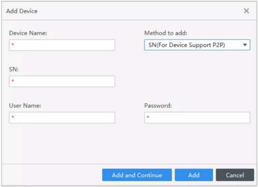
text_image
Add Device Device Name: * SN: * User Name: * Method to add: SN(For Device Support P2P) Password: * Add and Continue Add CancelTable 3-4 Parameters of SN adding
| Parameter Description | |
| Method to add Select | SN (For Device Support P2P). |
| SN | Enter the serial number of the device. |
Step 3 Click Add to add the device, and then close the Add Device page; or click Add and Continue to add the device and stay on the Add Device page so that you can add another device conveniently.
3.5 Department Management
You can add, modify or delete department. Here uses the department adding as an example.
Procedure
Step 1 Select Personnel > User Management.
Step 2 Click + in the Department List to add.
Step 3 Select a superior department, and then add a new sub-department.
Step 4 Click OK to confirm.
Figure 3-4 Add department

text_image
Department List + Search.. 1(2) 01(1)Figure 3-5 Add department information
text_image
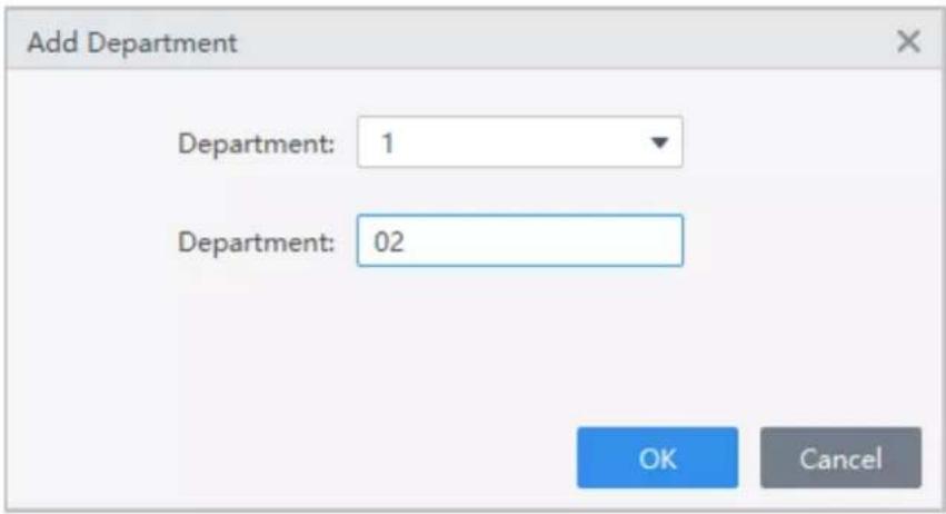
Add Department Department: 1 Department: 02 OK Cancel3.6 Adding Staff
Background Information
Select one of the methods to add staff.
- Add staff one by one manually.
- Add staff in batches.
3.6.1 Adding Staff One by One Manually
Procedure
Step 1 Select Personnel > User Management > Add.
Step 2 Enter basic information of staff.
1) Select Basic Info.
2) Add basic information of staff.
3) Take snapshot or upload picture, and then click Finish.

- The card number can be read automatically or filled in manually. To automatically read card number, select the card reader next to Card No., and then place the card on the card reader. The card number will be read automatically.
- You can select multiple USB cameras to snap pictures.
- Set password
Click Add to add the password. For second-generation access controllers, set person passwords; for other devices, set card passwords. New passwords must consist of 6-8 digits.
- Configure card
- Click to select Device or Card issuer as card reader.
- Add card. The card number must be added if the non-second generation access controller is used.
- After adding, you can select the card as main card or duress card, or replace the card with a new one, or delete the card.
- Click ■ to display the QR code of the card.

Only 8-digit card number in hexadecimal mode can display the QR code of the card.
- Configure fingerprint
- Click to select Device or Fingerprint Scanner as the fingerprint collector.
- Add fingerprint. Select Add > Add Fingerprint, and then press finger on the scanner for three times continuously.
Figure 3-6 Add basic information

text_image
Add User Basic Info Extended information Permission User ID: * Name: * Department: Default Company User Type: General User Validity Time: 2022/11/29 0:00:00 2032/11/29 23:59:59 Times Used: Unlimited Take Snapshot Upload Picture Image Size: 0-100 KB Take Snapshot Upload Picture Image Size: 0-100 KB Password Add For the 2nd-generation access controller, it is the person password; otherwise it is the card password. Card Add The card number must be added if non-2nd generation access controller is used. Fingerprint + Add Delete Fingerprint Name Operation Add More Finish CancelStep 3 Select Personnel > User Management > Add > Certification to add the extended information of the staff, and then clickFinish to save.
Figure 3-7 Add extended information

text_image
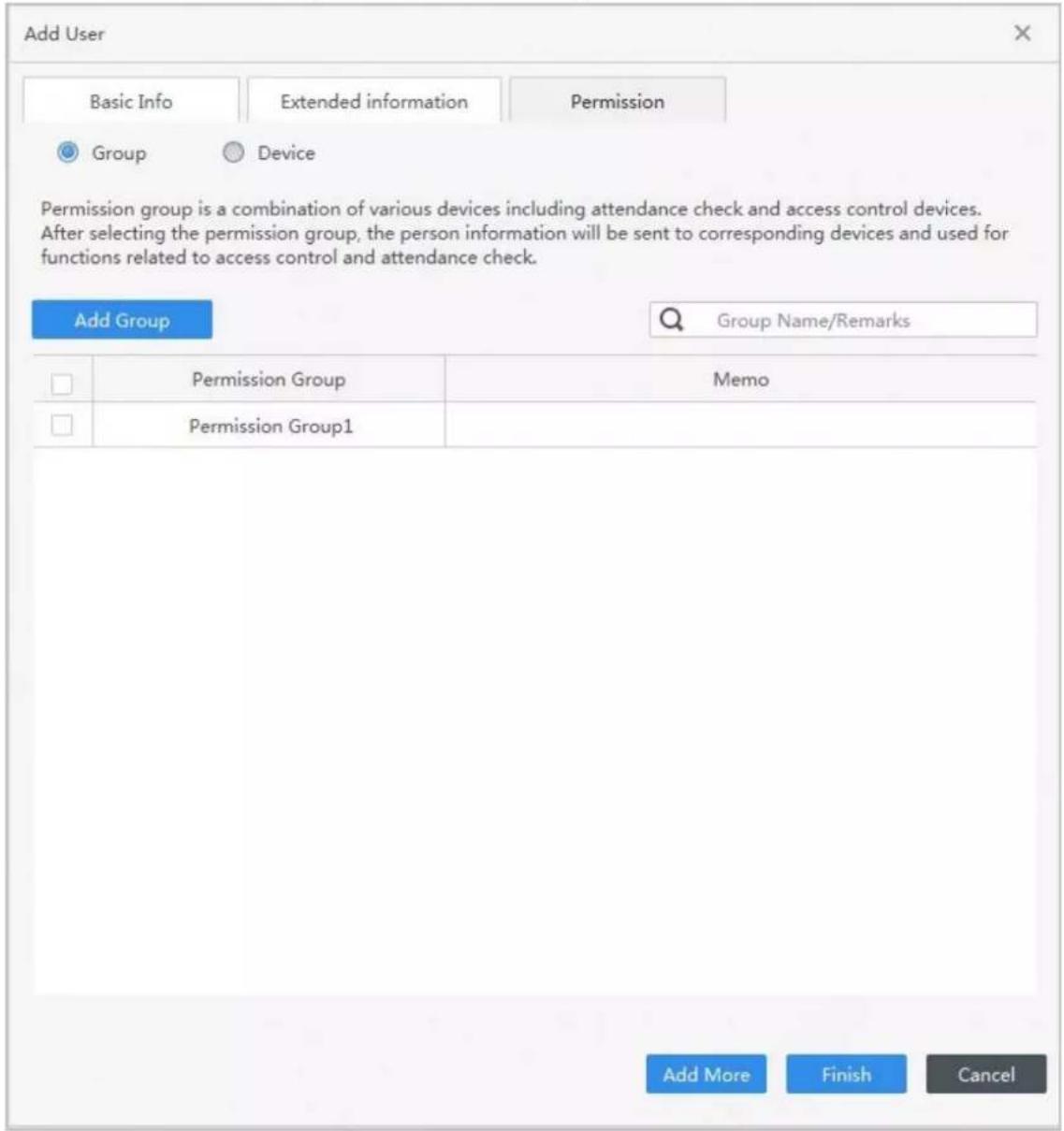
Add User Basic Info Extended information Permission Details Gender: Male Female ID Type: ID Title: Mr ID No.: Date of Birth: 1985/3/15 Company: Tel: Occupation: Email: Employment Date: 2022/11/28 19:38:45 Mailing Address: Termination Date: 2032/11/29 19:38:45 Administrator: Remark: Add More Finish CancelStep 4 Configure permissions.
Figure 3-8 Permission configuration
text_image
Add User Basic Info Extended information Permission Group Device Permission group is a combination of various devices including attendance check and access control devices. After selecting the permission group, the person information will be sent to corresponding devices and used for functions related to access control and attendance check. Add Group Group Name/Remarks □ Permission Group Memo □ Permission Group1 Add More Finish CancelStep 5 Click Finish.
3.6.2 Adding Staff in Batches
Procedure
Step 1 Select Personnel > User Management > Batch Update > Batch Add.
Step 2 Select card reader and the department of staff. Set the start number, number of card, effective time and expired time of card.
Step 3 Click Read Card No., and then the card number will be read automatically.
Step 4 Click OK.
Figure 3-9 Add staff in batches
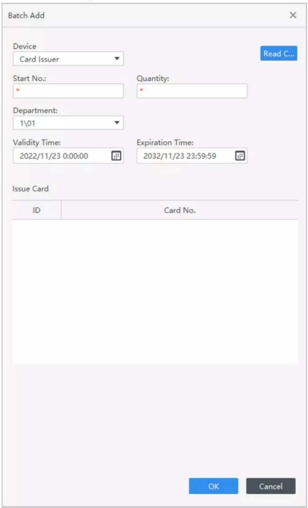
text_image
Batch Add Device Card Issuer Read C... Start No.: Quantity: * Department: 1\01 Validity Time: 2022/11/23 0:00:00 Expiration Time: 2032/11/23 23:59:59 Issue Card ID Card No. OK CancelStep 5 In the list of staff, click ✅ to modify information or add details of staff.
3.7 Permission Configuration
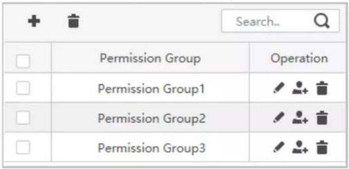
3.7.1 Adding Permission Group
Procedure
Step 1 Select Personnel > Permission Configuration.
Step 2 Click + to add a permission group.
Step 3 Set permission parameters.
1) Enter group name and remark.
2) Select the needed time template.

For details on time template setting, see SmartPSS-Lite_Access Control Solution_User's Manual.
3) Select the verification method.
4) Select the corresponding device, such as door 1.
Figure 3-10 Add permission group (1)
text_image
+ Search.. Q □ Permission Group Operation □ Permission Group1 ✓ + □ Permission Group2 ✓ + □ Permission Group3 ✓ +Figure 3-11 Add permission group (2)

text_image
Add Permission Group Basic Info Group Name Permission Group4 Remark: Time Templ... All Day Time Ten▼ Verification Method: ✓ Card ✓ Fingerprint ✓ Password ✓ Face All Device Selected (0) Search... Default Group ✓ Door 1 OK CancelStep 4 Click OK to save operations.
3.7.2 Assigning Permissions
Associate users with the permission group so that users can check attendance on the Device.
Procedure
Step 1 Select Personnel > Permission Configuration.
Step 2 Click 🎥, and select users or you can select a whole department.
Step 3 Click OK.
Figure 3-12 Assign permissions
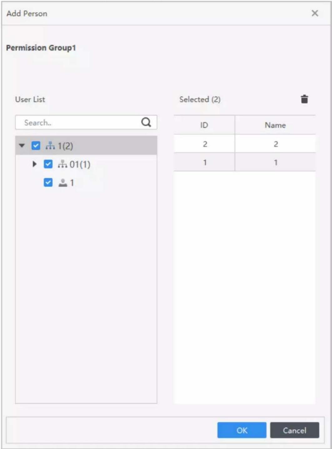
text_image
Add Person Permission Group1 User List Search... Selected (2) ID Name 2 2 1 1 OK CancelStep 4 Click OK.
3.8 Adding Attendance Period
Procedure
Step 1 Select Attendance > Attendance Period.
Step 2 Click Add, and then set the basic information on the period, attendance period and attendance rule.
Figure 3-13 Add attendance periods

text_image
Add Delete Name Mode Operation Default Ti... FixedStep 3 Configure attendance period parameters.

- You can mark the attendance period in color. When you arrange and apply shifts, the color will be displayed in the calendar.
- Start work time of the current period must not be earlier than end work time of the previous period.
- After enabling Use First Check-In and Last Check-Out Only, the attendance record will only take the earliest and latest record within the valid check-in and check-out time range. Otherwise, multiple working periods will appear by pairing records according to the valid check-in and check-out time range.
- Fixed type: Set the working hour, valid check-in time, valid check-out time and more. The attendance period is fixed. For fixed type, you can add up to 8 attendance periods. For the fixed type, you can add a rest period, and you can add up to 7 rest periods. Click Configure Rest Period to set the rest periods, and then click Add to add the rest period to the list.
• Figure 3-14 Set attendance period (fixed type)

text_image
Period Details ? Device Model Fixed Flexible Rest Basic Info Timezon... Color: Blue Attendance Period: Work Time: 08:30 - 17:30 The time span must not exceed 24 hours. Record as: 540.0 Valid Check-in Time: 06:30 - Valid Check-out Time: 19:30 Use First Check-In and Last Check-Out Only Attendance Rule: Must not be late for more than 5.00 minutes is permitted. Late sign in over 120.00 minutes is recorded as absence. Early leave within 5.00 minutes is permitted. Save CancelFigure 3-15 Rest period

text_image
Period Details Model Fixed Flexible Rest Basic Info Add Configure Rest Period Name Start Time End Time Validity Start Time Validity End Time Rest Period(Minure) Auto Deduction Must Check In/Out Transfer Unused Rest Time to Valid Work Time Remark ? 12:00 13:10 12:00 12:10 10 Enable Disable Disable Save CancelFigure 3-16 Set rest periods

text_image
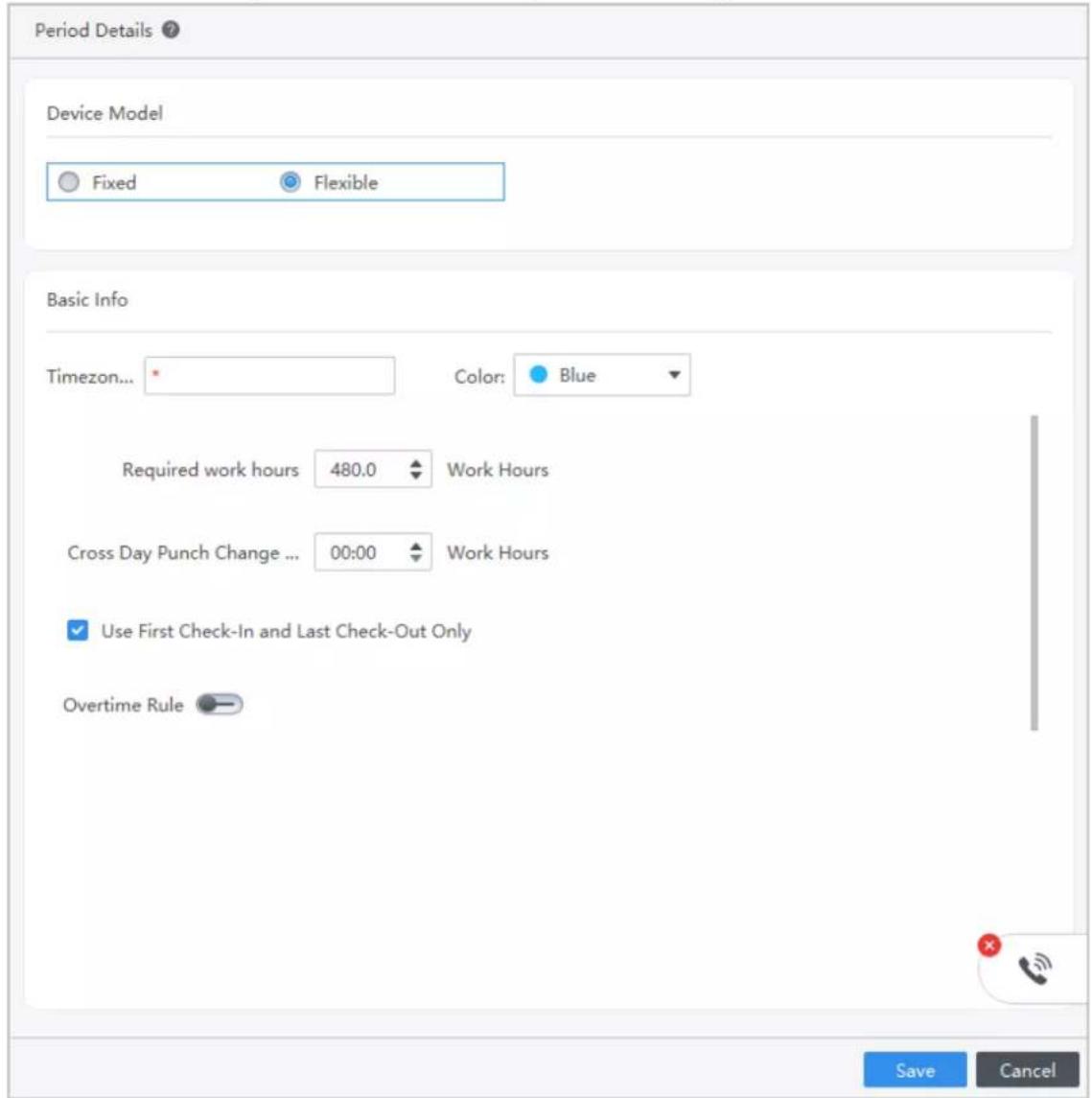
Set Rest Period Add Delete Rest Name 1 Start Time 01:00 End Time 02:00 Rest Period 60.00 Minute Auto Deduction Must Check In/Out- Flexible type: Set the required working hour of a day. The checking time is flexible.
Figure 3-17 Set attendance period (flexible type)
text_image
Period Details ? Device Model Fixed Flexible Basic Info Timezon... Color: Blue Required work hours 480.0 Work Hours Cross Day Punch Change ... 00:00 Work Hours Use First Check-In and Last Check-Out Only Overtime Rule Save CancelStep 4 Click Save.
3.9 Adding Attendance Shift
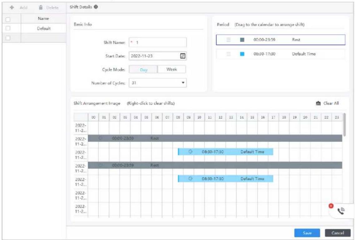
You can arrange shift by day or week. Here uses the weekly shift as an example.
Procedure
Step 1 Select Attendance > Attendance Shift.
Step 2 Click Add on the upper-left corner of page.
Step 3 Set the shift name, start date, cycle mode and cycle period, and then drag the period to the calendar to arrange the shift.
Click Clear All to clear all the settings.
Figure 3-18 Set attendance shift
text_image
Shift Details Basic Info Shift Name: 1 Start Date: 2022-11-23 Cycle Mode: Day Week Number of Cycles: 31 Period (Drag to the calendar to arrange shift) 00:00-23:59 Rest 08:30-17:30 Default Time Shift Arrangement Image (Right-click to clear shifts) Clear All 2022- 11-2... 2022- 11-2... 2022- 11-2... 2022- 11-2... 2022- 11-2... Save CancelStep 4 Click Save, and then click OK to confirm operation.
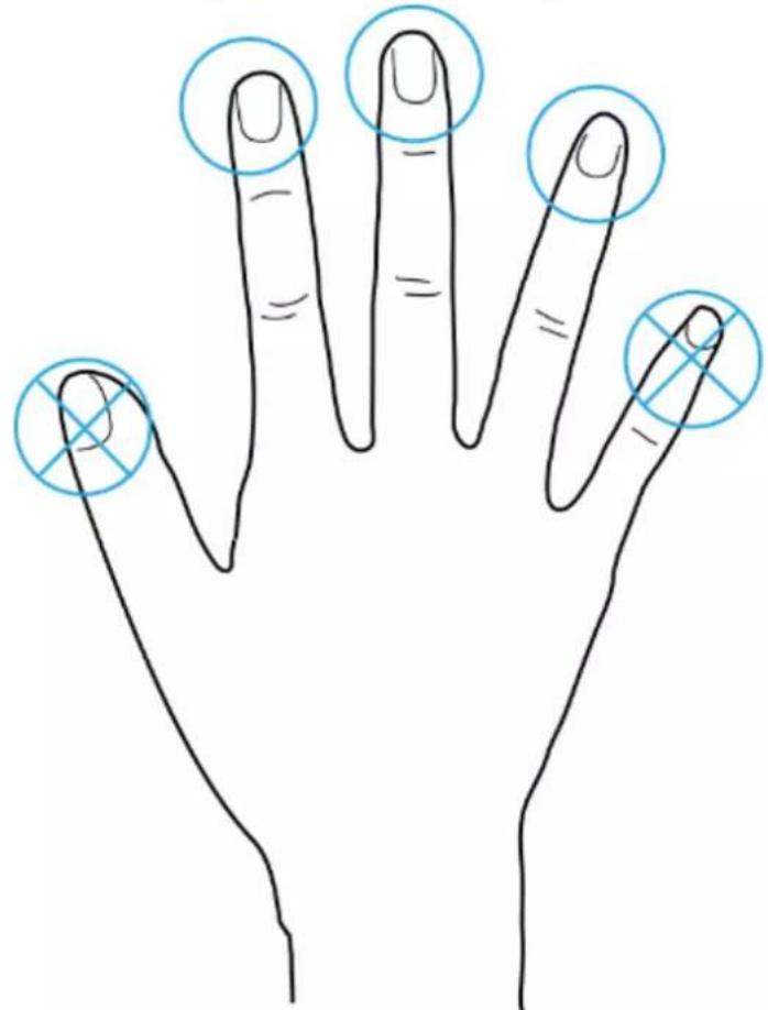
Appendix 1 Important Points of Fingerprint Registration Instructions
When you register the fingerprint, pay attention to the following points:
- Make sure that your fingers and the scanner surface are clean and dry.
- Press your finger on the center of the fingerprint scanner.
- Do not put the fingerprint sensor in a place with intense light, high temperature, and high humidity.
- If your fingerprints are unclear, use other unlocking methods.
Fingers Recommended
Forefingers, middle fingers, and ring fingers are recommended. Thumbs and little fingers cannot be put at the recording center easily.
Appendix Figure 1-1 Recommended fingers
natural_image
Line drawing of a human hand with five fingers and four marked points (no text or symbols)How to Press Your Fingerprint on the Scanner
Appendix Figure 1-2 Correct placement
natural_image
Line drawing of two fingers pointing at a square frame and a vertical line, with dashed lines indicating alignment or measurement (no text or symbols)Appendix Figure 1-3 Wrong placement
text_image
Diagram illustrating finger positioning and alignment of a rectangular object, showing top-down and side-up views with dashed lines indicating measurement or alignment.
text_image
Diagram showing two finger positioning methods with dashed lines indicating alignment or measurement.Appendix 2 Input Method
You can type English letters, numbers and symbols.
Numbers
- Tap ☐ to switch input methods until 123 is displayed on the screen.
- Enter numbers.
- Tap OK/F4 to confirm.
Letters
- Tap ☐*☐ to switch input methods until ABC is displayed on the screen.
- Enter letters.
- Tap OK/F4 to confirm.
Symbols
- Tap ☐ to switch input methods until :-) is displayed on the screen.
- Tap ∧/F2 orv/F3 to select symbols.
- Tap OK/F4 to confirm.
Appendix 3 FAQ
• Q: The Device prompts me to do it again after I have placed my finger on the sensor.
A: Check if your fingerprints have been registered.
• Q: The bell does not ring.
A: Check if bell ring is set successfully and the broadcast volume switch is on.
• Q: I cannot update the Device through the USB.
A: Check if the Device is successfully recognized by the Device, and check the update file name.
• Q: Failed to export by USB flash drive.
A: Use USB in FAT32 format.
• Q: I forget administrator password.
A: Contact the manufacturer.
• Q: How to search for user attendance record?
A: On the standby screen, tap #, and then place your finger on the fingerprint sensor, or enter the user ID and password, or swipe the card.
Appendix 4 Cybersecurity Recommendations
Mandatory actions to be taken for basic equipment network security:
1. Use Strong Passwords
Please refer to the following suggestions to set passwords:
- The length should not be less than 8 characters.
- Include at least two types of characters; character types include upper and lower case letters, numbers and symbols.
- Do not contain the account name or the account name in reverse order.
- Do not use continuous characters, such as 123, abc, etc.
- Do not use overlapped characters, such as 111, aaa, etc.
2. Update Firmware and Client Software in Time
- According to the standard procedure in Tech-industry, we recommend to keep your equipment (such as NVR, DVR, IP camera, etc.) firmware up-to-date to ensure the system is equipped with the latest security patches and fixes. When the equipment is connected to the public network, it is recommended to enable the "auto-check for updates" function to obtain timely information of firmware updates released by the manufacturer.
- We suggest that you download and use the latest version of client software.
"Nice to have" recommendations to improve your equipment network security:
1. Physical Protection
We suggest that you perform physical protection to equipment, especially storage devices. For example, place the equipment in a special computer room and cabinet, and implement well-done access control permission and key management to prevent unauthorized personnel from carrying out physical contacts such as damaging hardware, unauthorized connection of removable equipment (such as USB flash disk, serial port), etc.
2. Change Passwords Regularly
We suggest that you change passwords regularly to reduce the risk of being guessed or cracked.
3. Set and Update Passwords Reset Information Timely
The device supports password reset function. Please set up related information for password reset in time, including the end user's mailbox and password protection questions. If the information changes, please modify it in time. When setting password protection questions, it is suggested not to use those that can be easily guessed.
4. Enable Account Lock
The account lock feature is enabled by default, and we recommend you to keep it on to guarantee the account security. If an attacker attempts to log in with the wrong password several times, the corresponding account and the source IP address will be locked.
5. Change Default HTTP and Other Service Ports
We suggest you to change default HTTP and other service ports into any set of numbers between 1024–65535, reducing the risk of outsiders being able to guess which ports you are using.
6. Enable HTTPS
We suggest you to enable HTTPS, so that you visit Web service through a secure communication channel.
7. MAC Address Binding
We recommend you to bind the IP and MAC address of the gateway to the equipment, thus reducing the risk of ARP spoofing.
8. Assign Accounts and Privileges Reasonably
According to business and management requirements, reasonably add users and assign a
minimum set of permissions to them.
9. Disable Unnecessary Services and Choose Secure Modes
If not needed, it is recommended to turn off some services such as SNMP, SMTP, UPnP, etc., to reduce risks.
If necessary, it is highly recommended that you use safe modes, including but not limited to the following services:
- SNMP: Choose SNMP v3, and set up strong encryption passwords and authentication passwords.
- SMTP: Choose TLS to access mailbox server.
- FTP: Choose SFTP, and set up strong passwords.
- AP hotspot: Choose WPA2-PSK encryption mode, and set up strong passwords.
10. Audio and Video Encrypted Transmission
If your audio and video data contents are very important or sensitive, we recommend that you use encrypted transmission function, to reduce the risk of audio and video data being stolen during transmission.
Reminder: encrypted transmission will cause some loss in transmission efficiency.
11. Secure Auditing
- Check online users: we suggest that you check online users regularly to see if the device is logged in without authorization.
- Check equipment log: By viewing the logs, you can know the IP addresses that were used to log in to your devices and their key operations.
12. Network Log
Due to the limited storage capacity of the equipment, the stored log is limited. If you need to save the log for a long time, it is recommended that you enable the network log function to ensure that the critical logs are synchronized to the network log server for tracing.
13. Construct a Safe Network Environment
In order to better ensure the safety of equipment and reduce potential cyber risks, we recommend:
- Disable the port mapping function of the router to avoid direct access to the intranet devices from external network.
- The network should be partitioned and isolated according to the actual network needs. If there are no communication requirements between two sub networks, it is suggested to use VLAN, network GAP and other technologies to partition the network, so as to achieve the network isolation effect.
- Establish the 802.1x access authentication system to reduce the risk of unauthorized access to private networks.
- Enable IP/MAC address filtering function to limit the range of hosts allowed to access the device.