
ASC2102B-T - Access Control System Dahua Technology - Free user manual and instructions
Find the device manual for free ASC2102B-T Dahua Technology in PDF.


| Product Type | Access Control System (Standalone Controller) |
| Model | ASC2102B-T |
| Brand | Dahua Technology |
| Dimensions | 120 mm x 80 mm x 25 mm (approximate) |
| Weight | 0.3 kg (approximate) |
| Power Supply | 12V DC, 500 mA (via external power adapter) |
| Supported Card Types | 13.56 MHz, EM 125 kHz (via optional reader) |
| User Capacity | Up to 3,000 users |
| Log Storage | Up to 100,000 events |
| Communication | TCP/IP, RS-485, Wiegand input/output |
| Input Voltage Range | 9V - 16V DC |
| Operating Temperature | -20°C to +60°C |
| Operating Humidity | 10% to 90% (non-condensing) |
| Enclosure Rating | IP65 (indoor/outdoor use) |
| Display | 2-line LCD with backlight |
| Keypad | 12-key backlit keypad |
| Tamper Switch | Built-in |
| Installation | Wall-mounted using included bracket |
| Certifications | CE, FCC |
| Maintenance | Clean with a damp cloth; avoid harsh chemicals |
| Security | Anti-passback, duress code, tamper alarm |
| Spare Parts | Power adapter, mounting kit, optional external reader |
| Repairability | Modular design; replaceable components |
Frequently Asked Questions - ASC2102B-T Dahua Technology
User questions about ASC2102B-T Dahua Technology
0 question about this device. Answer the ones you know or ask your own.
Ask a new question about this device
Download the instructions for your Access Control System in PDF format for free! Find your manual ASC2102B-T - Dahua Technology and take your electronic device back in hand. On this page are published all the documents necessary for the use of your device. ASC2102B-T by Dahua Technology.
USER MANUAL ASC2102B-T Dahua Technology
Two-door Sub Access Controller
User's Manual
Cybersecurity Recommendations
The necessary measures to ensure the basic cyber security of the platform:
1. Use Strong Passwords
- Please refer to the following suggestions to set passwords:
The length should not be less than 8 characters.
Include at least two types of characters; character types include upper and lower case letters, numbers and symbols.
Do not contain the account name or the account name in reverse order.
Do not use continuous characters, such as 123, abc, etc.
Do not use overlapped characters, such as 111, aaa, etc.
2. Customize the Answer to the Security Question
- The security question setting should ensure the difference of answers, choose different questions and customize different answers (all questions are prohibited from being set to the same answer) to reduce the risk of security question being guessed or cracked.
- Recommendation measures to enhance platform cyber security:
1. Enable Account Binding IP/MAC
- It is recommended to enable the account binding IP/MAC mechanism, and configure the IP/MAC of the terminal where the commonly used client is located as an allowlist to further improve access security.
2. Change Password Regularly
- We suggest that you change passwords regularly to reduce the risk of being guessed or cracked.
3. Turn On Account Lock Mechanism
- The account lock function is enabled by default at the factory, and it is recommended to keep it on to protect the security of your account. After the attacker has failed multiple password attempts, the corresponding account and source IP will be locked.
4. Reasonable Allocation of Accounts and Permissions
- According to business and management needs, reasonably add new users, and reasonably allocate a minimum set of permissions for them.
5. Close Non-essential Services and Restrict the Open Form of Essential Services
- If not needed, it is recommended to turn off NetBIOS (port 137, 138, 139), SMB (port 445), remote desktop (port 3389) and other services under Windows, and Telnet (port 23) and SSH (port 22) under Linux. At the same time, close the database port to the outside or only open to a specific IP address, such as MySQL (port 3306), to reduce the risks faced by the platform.
6. Patch the Operating System/Third Party Components
- It is recommended to regularly detect security vulnerabilities in the operating system and third-party components, and apply official patches in time.
7. Security Audit
Check online users: It is recommended to check online users irregularly to identify whether there are illegal users logging in.
View the platform log: By viewing the log, you can get the IP information of the attempt to log in to the platform and the key operation information of the logged-in user.
8. The Establishment of a Secure Network Environment
- In order to better protect the security of the platform and reduce cyber security risks, it is recommended that:
Follow the principle of minimization, restrict the ports that the platform maps externally by firewalls or routers, and only map ports that are necessary for services.
Based on actual network requirements, separate networks: if there is no communication requirement between the two subnets, it is recommended to use VLAN, gatekeeper, etc. to divide the network to achieve the effect of network isolation.
Foreword
General
This document elaborates on structure, installation, interface and wiring of two-door sub access controller.
Safety Instructions
The following categorized signal words with defined meaning might appear in the Manual.
| Signal Words Meaning | |
 DANGER DANGER | Indicates a high potential hazard which, if not avoided, will result in death or serious injury. |
 WARNING WARNING | Indicates a medium or low potential hazard which, if not avoided, could result in slight or moderate injury. |
 CAUTION CAUTION | Indicates a potential risk which, if not avoided, could result in property damage, data loss, lower performance, or unpredictable result. |
 TIPS TIPS | Provides methods to help you solve a problem or save you time. |
 NOTE NOTE | Provides additional information as the emphasis and supplement to the text. |
Privacy Protection Notice
As the device user or data controller, you might collect personal data of others' such as face, fingerprints, car plate number, Email address, phone number, GPS and so on. You need to be in compliance with the local privacy protection laws and regulations to protect the legitimate rights and interests of other people by implementing measures include but not limited to: providing clear and visible identification to inform data subject the existence of surveillance area and providing related contact.
About the Manual
- The Manual is for reference only. If there is inconsistency between the Manual and the actual product, the actual product shall prevail.
- We are not liable for any loss caused by the operations that do not comply with the Manual.
- The Manual would be updated according to the latest laws and regulations of related regions. For detailed information, see the paper User's Manual, CD-ROM, QR code or our official website. If there is inconsistency between paper User's Manual and the electronic version, the electronic version shall prevail.
-
All the designs and software are subject to change without prior written notice. The product updates might cause some differences between the actual product and the Manual. Please contact the customer service for the latest program and supplementary documentation.
-
There still might be deviation in technical data, functions and operations description, or errors in print. If there is any doubt or dispute, please refer to our final explanation.
- Upgrade the reader software or try other mainstream reader software if the Guide (in PDF format) cannot be opened.
- All trademarks, registered trademarks and the company names in the Manual are the properties of their respective owners.
- Please visit our website, contact the supplier or customer service if there is any problem occurred when using the device.
- If there is any uncertainty or controversy, please refer to our final explanation.
Important Safeguards and Warnings
The following description is the correct application method of the device. Please read the manual carefully before use, in order to prevent danger and property loss. Strictly conform to the manual during application and keep it properly after reading.
Operating Requirement
- Please don't place and install the device in an area exposed to direct sunlight or near heat generating device.
- Please don't install the device in a humid, dusty or fuliginous area.
- Please keep its horizontal installation, or install it at stable places, and prevent it from falling.
- Please don't drip or splash liquids onto the device; don't put on the device anything filled with liquids, in order to prevent liquids from flowing into the device.
- Please install the device at well-ventilated places; don't block its ventilation opening.
- Use the device only within rated input and output range.
- Please don't dismantle the device arbitrarily.
- Please transport, use and store the device within allowed humidity and temperature range.
Power Requirement
- Please make sure to use batteries according to requirements; otherwise, it may result in fire, explosion or burning risks of batteries!
- To replace batteries, only the same type of batteries can be used!
- The product shall use electric cables (power cables) recommended by this area, which shall be used within its rated specification!
- Please use standard power adapter matched with the device. Otherwise, the user shall undertake resulting personnel injury or device damage.
- Please use power supply that meets SELV (safety extra low voltage) requirements, and supply power with rated voltage that conforms to Limited Power Source in IEC60950-1. For specific power supply requirements, please refer to device labels.
- Products with category I structure shall be connected to grid power output socket, which is equipped with protective grounding.
- Appliance coupler is a disconnecting device. During normal use, please keep an angle that facilitates operation.
Table of Contents
Cybersecurity Recommendations ....I
Foreword....III
Important Safeguards and Warnings......V
1 Overview....1
2 Packing List.... 2
3 Installation Guide .... 3
3.1 System Structure .... 3
3.2 External Dimension....3
3.3 Device Installation 4
3.4 Disassembly ....5
3.5 Wiring Description....6
1.1.1 Wiring Description of CAN Bus 7
3.5.2 Wiring Description of Exit Button/Door Sensor....7
3.5.3 Wiring Description of External Alarm Input....8
3.5.4 Wiring Description of External Alarm Output 8
3.5.5 Wiring Description of Lock 9
3.5.6 Wiring Description of Internal Alarm Output....10
3.5.7 Wiring Description of Reader ....10
3.6 DIP Switch....11
3.7 Reboot....12
4 Technical Parameters .... 13
1 Overview
As a sub main controller of main access controller, two-door sub access controller is matched with main access controller and is widely used in banks, safe places, and more.
Its rich functions are as follows:
- Adopt sliding rail type and lock type installation, convenient installation and maintenance.
• Integrate alarm and fire alarm.
• Support 4 sets of card readers. - Support 9 groups of signal input (exit button *2, door sensor *2 and intrusion alarm *5).
● Support 5 groups of control output (electric lock *2 and alarm output *3). - With RS485 port, it may extend to connect lift control module, alarm or household control module.
• Support CAN bus and connect main access controller. - FLASH storage capacity is 16M (which may extend to 32M), max supports 20,000 card holders and 30,000 offline records.
- Support illegal intrusion alarm, exit overtime alarm, duress card alarm and duress code setup. Also support blocklist and allowlist and patrol card setup.
● Data storage during outage, built-in RTC (support DST), online upgrading.

Caution
If this product needs to connect external power supply, please use 12V 0.5 A adapter and ensure that
working temperature shall not exceed -5^ +55^ .
2 Packing List
Before installation, please check according to the table below.
Table 2-1
| No. Name Quantity | ||
| 1 Access controller 1 | ||
| 2 Installation positioning drawing 1 | ||
| 3 | Accessory kit (screw, expansion pipe and wiring terminal) | 1 |
| 4 Quick start guide 1 | ||
| 5 Certificate of qualification 1 | ||
3 Installation Guide
3.1 System Structure
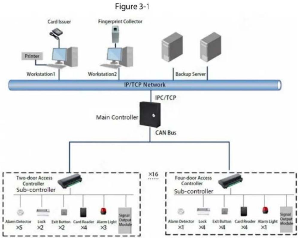
flowchart
graph TD
    A["Printer"] --> B["Workstation1"]
    C["Card Issuer"] --> D["Workstation2"]
    E["Fingerprint Collector"] --> F["Workstation2"]
    G["Backup Server"] --> H["Workstation2"]
    I["IP/TCP Network"] --> J["IPC/TCP"]
    J --> K["Main Controller"]
    K --> L["CAN Bus"]
    L --> M["Two-door Access Controller Sub-controller"]
    M --> N["Alarm Detector ×5"]
    M --> O["Lock ×2"]
    M --> P["Exit Button ×2"]
    M --> Q["Card Reader ×4"]
    M --> R["Alarm Light ×3"]
    M --> S["Signal Output Module"]
    T["Four-door Access Controller Sub-controller"] --> U["Alarm Detector ×1"]
    T --> V["Lock ×4"]
    T --> W["Exit Button ×4"]
    T --> X["Card Reader ×4"]
    T --> Y["Alarm Light ×1"]
    T --> Z["Signal Output Module"]
3.2 External Dimension
The unit is mm.
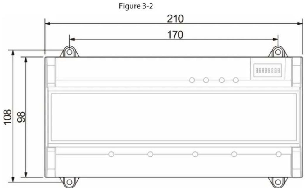
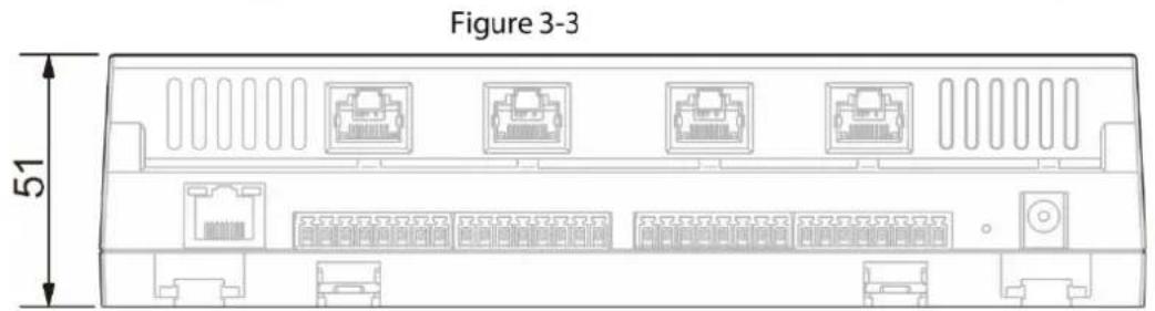
3.3 Device Installation
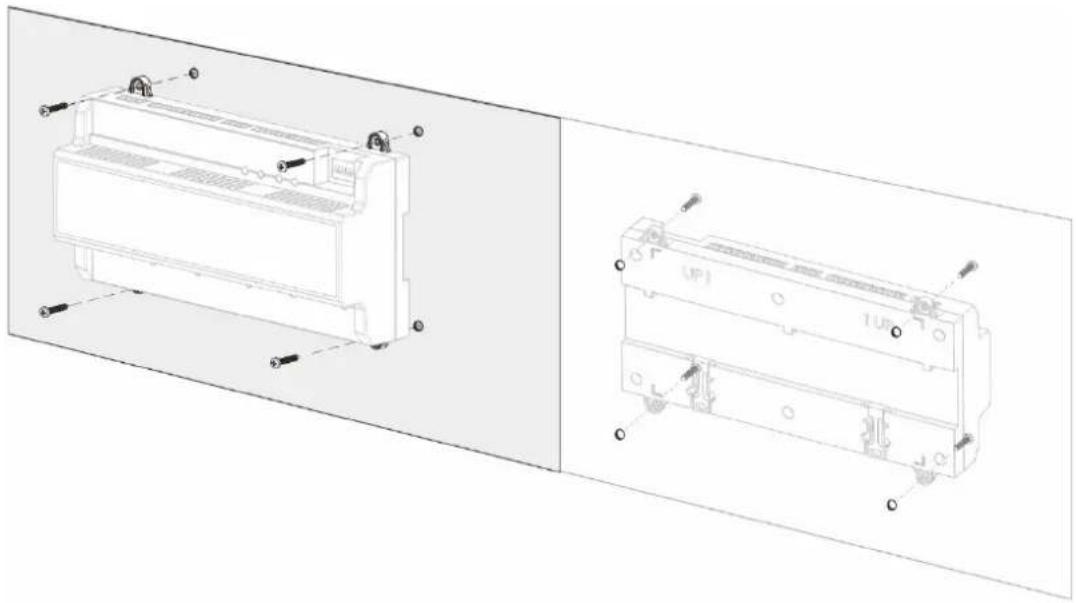
There are two installation modes.
● Mode 1: fix the whole device onto the wall with screws.
- Mode 2: install U-shaped guide rail, and hang the whole device onto the wall (U-shaped guide rail is a self-bought fitting).
Mode 1
Installation diagram is shown below.
Figure 3-4
natural_image
Technical line drawing of a dual-chamber air conditioner unit with mounting holes and internal components (no text or symbols)Mode 2
Installation diagram is shown below.
Figure 3-5
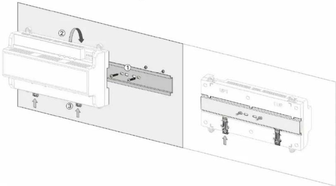
Step 1 Fix the U-shaped guide rail onto the wall with screws.
Step 2 Buckle the upper rear part of the device into upper groove of U-shaped guide rail.
Step 3 Push the snap joint at the bottom of the device upwards. The installation is completed when you hear the fitting sound.
3.4 Disassembly
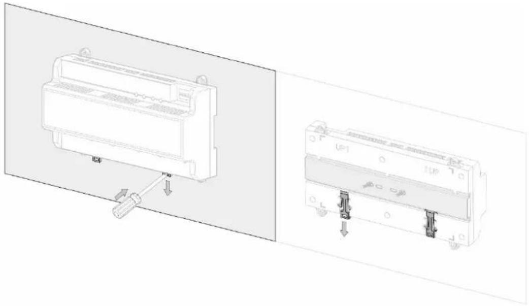
If the device is installed with mode 2, please disassemble it according to the picture below.
Align a screwdriver with the snap joint, press it down and the snap joint will pop up, so the whole device can be disassembled smoothly.
Figure 3-6
natural_image
Technical line drawing of a device component with two views: one showing a pin inserted into a housing, the other showing a close-up of its internal structure (no text or symbols visible)3.5 Wiring Description
Device wiring diagram is shown below.
Figure 3-7
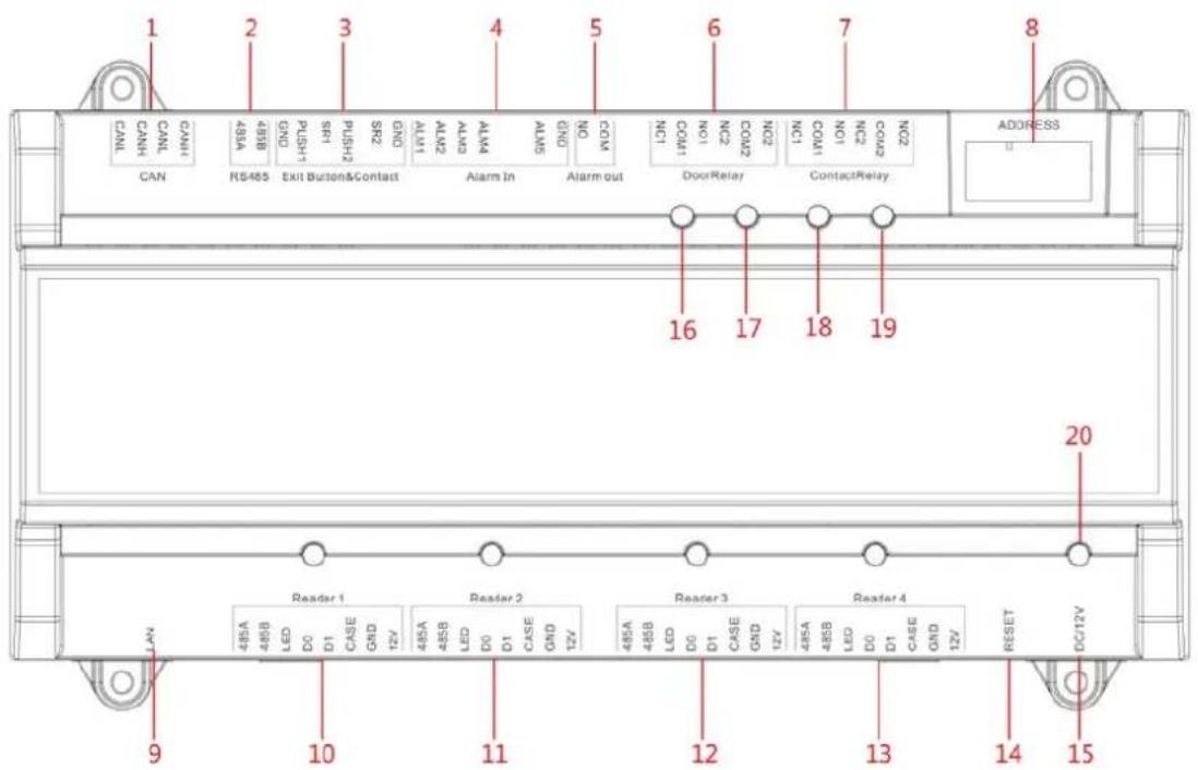
Interfaces are described in the table below.
Table 3-1
| No. | Interface Description | No. | Interface Description |
| 1 | CAN bus | 9 | Not available at present |
| 2 | External extension module | 10 | Entry reader of door 1 |
| 3 | Door sensor and exit button | 11 | Exit reader of door 1 |
| 4 | External alarm input | 12 | Entry reader of door 2 |
| 5 | External alarm output | 13 | Exit reader of door 2 |
| 6 | Lock control output | 14 | Reboot |
| 7 | Internal alarm output | 15 | DC 12V power interface |
| 8 | Address code/transmission rate |
Indicator lights are described in the table below.
Table 3-2
| No. Description | |
| 16 | Lock status indicator |
| 17 | |
| 18 | Alarm status indicator |
| 19 | |
| 20 Power indicator |
1.1.1 Wiring Description of CAN Bus
Wiring terminals of CAN bus are described in the table below.
Table 3-3
| Interface | Wiring Terminal | Description |
| CAN bus | CANL | CAN bus input |
| CANH | ||
| CANL | CAN bus output | |
| CANH |
3.5.2 Wiring Description of Exit Button/Door Sensor
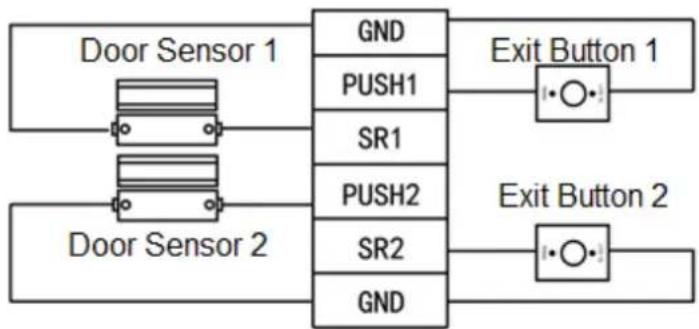
Corresponding wiring terminals of exit button and door sensor are shown in Figure 3-8. Please refer to Table 3-4 for descriptions of wiring terminals.
Figure 3-8
flowchart
graph LR
    A["Door Sensor 1"] --> B["GND"]
    C["Door Sensor 2"] --> D["PUSH1"]
    C --> E["SR1"]
    F["Exit Button 1"] --> G["•○•"]
    H["Exit Button 2"] --> I["•○•"]
    B --> J["PSH2"]
    D --> K["PSH2"]
    E --> L["PSH2"]
    F --> M["PSH2"]
    G --> N["PSH2"]
    H --> O["PSH2"]
Table 3-4
| Interface | Wiring Terminal | Description |
| Exit button+ door sensor | GNDPUSH1 Exit button of door 1 | Shared by exit button of door 1 and door sensor input of door 1 |
| SR1 Door sensor input of door 1 | ||
| PUSH2 Exit button of door 2 | ||
| SR2 Door sensor input of door 2 | ||
| GND | Shared by exit button of door 2 and door sensor input of door 2 |
3.5.3 Wiring Description of External Alarm Input
Figure 3-9
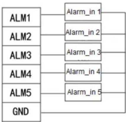
flowchart
graph LR
    A["ALM1"] --> B["Alarm_in 1"]
    C["ALM2"] --> D["Alarm_in 2"]
    E["ALM3"] --> F["Alarm_in 3"]
    G["ALM4"] --> H["Alarm_in 4"]
    I["ALM5"] --> J["Alarm_in 5"]
    K["GND"] --> L["End"]
Table 3-5
| Interface | Wiring Terminal | Description | |
| External alarm input | ALM1 Alarm input interface 1 | External alarm input interfaces are able to connect smoke detector and IR detector etc.. | |
| ALM2 Alarm input interface 2 | |||
| ALM3 Alarm input interface 3 | |||
| ALM4 Alarm input interface 4 | |||
| ALM5 | Alarm input interface 5 (reserved) | ||
| GND | Shared by alarm input interface 1, 2, 3, 4 and 5 | ||
3.5.4 Wiring Description of External Alarm Output
There are two connection modes of external alarm output, depending on alarm device. For example, IPC can use Mode 1, whereas audible and visual siren can use Mode 2, as shown in Fig 3-10 and Fig 3-11. Please refer to the table below for descriptions about wiring terminals.
Figure 3-10
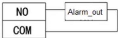
flowchart
graph LR
    A["NO"] --> B["Alarm_out"]
    C["COM"] --> B
Figure 3-11
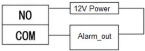
flowchart
graph TD
    A["NO"] --> B["12V Power"]
    C["COM"] --> D["Alarm_out"]
Table 3-6
| Interface | Wiring Terminal | Description |
| External alarm output | NO | External alarm output interfaces are able to connect audible and visual sirens. |
| COM |
3.5.5 Wiring Description of Lock
Support 2 groups of lock control outputs; serial numbers after the terminals represent corresponding doors. Please choose a proper connection mode according to lock type, as shown in Fig 3-12, Fig 3-13 and Fig 3-14. Please refer to table below for descriptions of wiring terminals.
Figure 3-12
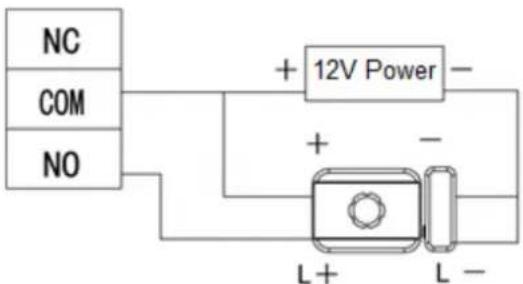
Figure 3-13
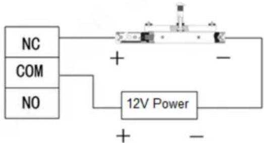
flowchart
graph TD
    A["NC"] --> B["+"]
    C["COM"] --> B
    D["NO"] --> B
    B --> E["12V Power"]
    E --> F["-"]
Figure 3-14
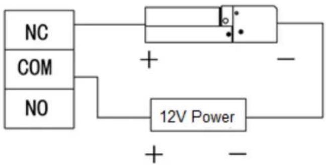
Table 3-7
| Interface | Wiring Terminal | Description |
| Lock control output | NC1 | Lock control of door 1 |
| COM1 | ||
| NO1 | ||
| NC2 | Lock control of door 2 | |
| COM2 | ||
| NO2 |
3.5.6 Wiring Description of Internal Alarm Output
Corresponding wiring terminals of internal alarm control output are shown below.
Table 3-8
| Interface | Wiring Terminal | Description |
| Internal alarm control output | NC1 | Intrusion, overtime and vandal-proof alarm output of door 1. Output time lasts for 15s. |
| COM1 | ||
| NO1 | ||
| NC2 | Intrusion, overtime and vandal-proof alarm output of door 2. Output time lasts for 15s. | |
| COM2 | ||
| NO42 |
3.5.7 Wiring Description of Reader

1 door only supports to connect one type of reader: RS-485 or Wiegand.
Please refer to Table 3-9 for descriptions of wiring terminals corresponding to readers. Take Door 1 for example, and other readers are the same as door 1. Please refer to the table below for descriptions of video cable specification and length.
Table 3-9
| Interface | Wiring Terminal | Cable Color | Description |
| Entry Reader of Door 1 | 485+ Purple | 485 reader | |
| 485- Yellow | |||
| LED Brown | Wiegand reader | ||
| D0 | Green | ||
| D1 | White | ||
| CASE | Blue | ||
| GND | Black | Reader power supply | |
| 12V | Red |
Table 3-10
| Reader Type | Connection Mode | Length |
| 485 Reader | CAT5e network cable, 485 connection | 100m |
| Wiegand Reader | CAT5e network cable, Wiegand connection | 30m |
3.6 DIP Switch
Set device number and speed with DIP switch. DIP switch is shown in the table below.
Table 3-11
| Function | No. Description | |
| Device Number | 1~5 | Set device number with binary system. The left is the lowest order. For example: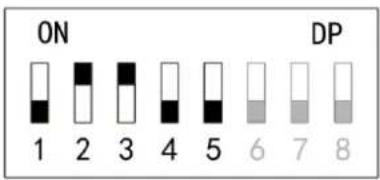 Binary representation 00110 corresponds to 6 in decimal system. Binary representation 00110 corresponds to 6 in decimal system. |
| Speed | 6~8 | Set the speed.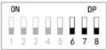 All of them are at the bottom, transmission speed is 50kb/s.Only digit 6 is at ON position, transmission speed is 80kb/s.Only digit 7 is at ON position transmission speed is 100kb/s.Digits 6 and 7 are at ON position transmission speed is 125kb/s. All of them are at the bottom, transmission speed is 50kb/s.Only digit 6 is at ON position, transmission speed is 80kb/s.Only digit 7 is at ON position transmission speed is 100kb/s.Digits 6 and 7 are at ON position transmission speed is 125kb/s. 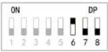 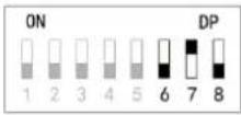 , ,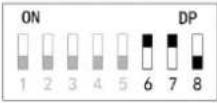 , , |
Table 3-11 for details.
the switch is at ON position, meaning 1.
the switch is at the bottom, meaning 0.


Figure 3-15
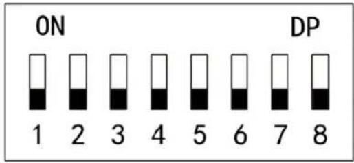
Table 3-12
| Function No. | Description | |
| Device Number | 1~5 | Set device number with binary system. The left is the lowest order. For example: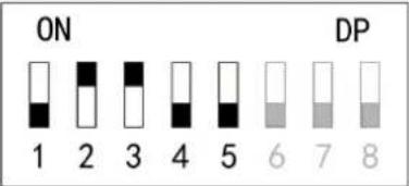 Binary representation 00110 corresponds to 6 in decimal system. Binary representation 00110 corresponds to 6 in decimal system. |
| Speed | 6~8 | Set the speed.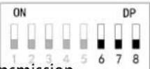 All of them are at the bottom ,transmission speed is 50kb/s. All of them are at the bottom ,transmission speed is 50kb/s.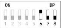 Only digit 6 is at ON position , transmission speed is 80kb/s. Only digit 6 is at ON position , transmission speed is 80kb/s.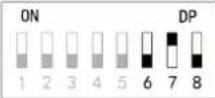 Only digit 7 is at ON position , transmission speed is 100kb/s. Only digit 7 is at ON position , transmission speed is 100kb/s.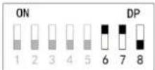 Digits 6 and 7 are at ON position , transmission speed is 125kb/s. Digits 6 and 7 are at ON position , transmission speed is 125kb/s. |
3.7 Reboot
Insert a needle into RESET hole, and long press the reboot controller.
4 Technical Parameters
| Parameter Specification | |
| Processor | 32-bit ARM processor |
| Storage Capacity 16M | |
| Max User 20,000 | |
| Max Record 30,000 | |
| Communication Port of Reader | Wiegand,RS485 |
| Communication Port CAN | |
| Quantity of Connected Reader 4 groups | |
| Working Power | Rated power 10V ~ 15V DC, rated current 0.75A |
| Real-time Monitoring Support | |
| Fire Alarm Linkage Support | |
| Vandal-proof Alarm | Support |
| Illegal Intrusion Alarm | Support |
| Unlock Overtime Alarm | Support |
| Duress Card Setup | Support |
| DST and Time Sync | Support |
| Online Upgrading | Support |
- Two-door Sub Access Controller
- User's Manual
- Cybersecurity Recommendations
- Use Strong Passwords
- Customize the Answer to the Security Question
- Enable Account Binding IP/MAC
- Change Password Regularly
- Turn On Account Lock Mechanism
- Reasonable Allocation of Accounts and Permissions
- Close Non-essential Services and Restrict the Open Form of Essential Services
- Patch the Operating System/Third Party Components
- Security Audit
- The Establishment of a Secure Network Environment
- Foreword
- General
- Safety Instructions
- Privacy Protection Notice
- About the Manual
- Important Safeguards and Warnings
- Operating Requirement
- Power Requirement
- Table of Contents
- Cybersecurity Recommendations ....I
- Foreword....III
- Important Safeguards and Warnings......V
- Overview....1
- Packing List.... 2
- Installation Guide .... 3
- Technical Parameters .... 13
- Overview
- Packing List
- Installation Guide
- System Structure
- External Dimension
- Device Installation
- Mode 1
- Mode 2
- Disassembly
- Wiring Description
- Wiring Description of CAN Bus
- Wiring Description of Exit Button/Door Sensor
- Wiring Description of External Alarm Input
- Wiring Description of External Alarm Output
- Wiring Description of Lock
- Wiring Description of Internal Alarm Output
- Wiring Description of Reader
- DIP Switch
- Reboot
- Technical Parameters
Brand : Dahua Technology
Model : ASC2102B-T
Category : Access Control System