WMicS2 - Microphone GODOX - Free user manual and instructions
Find the device manual for free WMicS2 GODOX in PDF.

| Product Type | Wireless Microphone System |
| Model | WMicS2 |
| Brand | Godox |
| Dimensions (Transmitter) | Approx. 4.5 x 2.5 x 1.2 cm |
| Dimensions (Receiver) | Approx. 6.5 x 4.5 x 1.5 cm |
| Weight (Transmitter) | Approx. 20 g |
| Weight (Receiver) | Approx. 35 g |
| Power Supply | Built-in rechargeable lithium battery (both units) |
| Battery Life | Up to 8 hours continuous use |
| Charging | USB-C charging cable included |
| Frequency Range | 2.4 GHz ISM band |
| Operating Range | Up to 100 meters (line of sight) |
| Microphone Type | Omnidirectional condenser lavalier |
| Audio Output | 3.5mm TRS jack (receiver) |
| Main Functions | Wireless audio transmission, mute function, volume control, easy pairing |
| Maintenance & Cleaning | Wipe with dry cloth; keep away from moisture and dust |
| Safety | Do not expose to extreme temperatures; use only approved charger |
| Spare Parts & Repairability | Replacement lavalier microphone and USB cables available; not user-serviceable internally |
| General Information | Ideal for vlogging, interviews, and content creation |
Frequently Asked Questions - WMicS2 GODOX
User questions about WMicS2 GODOX
0 question about this device. Answer the ones you know or ask your own.
Ask a new question about this device
Download the instructions for your Microphone in PDF format for free! Find your manual WMicS2 - GODOX and take your electronic device back in hand. On this page are published all the documents necessary for the use of your device. WMicS2 by GODOX.
USER MANUAL WMicS2 GODOX
GODOX Photo Equipment Co., Ltd.
Add: Building 2, Yaochuan Industrial Zone, Tangwei Community,
Fuhai Street, Bao'an District, Shenzhen 518103, China Tel: +86-755-29609320(8062)
Fax: +86-755-25723423 Email: godox@godox.com
www.godox.com
Made in China | 705-WMS200-01

WMicS2
小型UHF无线麦克风系统
UHF Compact Wireless Microphone System
使用手册
Instruction Manual
前言
感谢购买神牛产品!
text_image
Technical diagram of an eodax air conditioner unit with numbered components and labeled partstext_image
Technical diagram of a toolbox with labeled compartments and numbered partsnatural_image
Line drawing of a person wearing a suit with a small device attached (no text or symbols)((●)
natural_image
Line drawing of a DSLR camera with attached cable and connector (no text or symbols)
natural_image
Line drawing of a person wearing a suit jacket with a small object inserted into the chest (no text or symbols)((•))
natural_image
Diagram of a DSLR camera with attached antenna and cable, no text or symbols present发射器
Thank you for purchasing!
WMicS2 is a UHF compact wireless microphone system, the evolution and upgradation of S1 system. With the addition of charging case and upgradation of various functions, it provides a satisfying experience for live streaming, interview, video recording, journalistic shooting, audio recording, etc.
Please read this manual carefully before using to make sure the correct operation and exert the optimum function.
Main Features
• 96 wireless channels freely switchable without interference.
• The maximum wireless distance up to 200m.
• UHF Frequency Range: 514.56MHz-553.92MHz.
- With OLED display on transmitter to show the parameters setting.
- Provide output volume control and silent function, support real-time monitoring.
• Built-in chargeable lithium battery.
- Kit 2 includes charging case which provides both charging and storage functions.
• Support two transmitters and one receiver to work simultaneously.
- External SD card slot and internal recording function make it a voice recorder individually.
(Note: as the max. support frequency is 514.56MHz-553.92MHz which includes the 96 wireless channels frequency, there are parts of frequency may not be utilized.)
Warning
△ Do not disassemble. Should repairs become necessary, this product must be sent to an authorized maintenance center.
△ Always keep this product dry. Do not use in rain or in damp conditions.
△ Keep out of reach of children.
△ Do not use the flash unit in the presence of flammable gas. In certain circumstance, please pay attention to the relevant warnings.
Do not leave or store the product if the ambient temperature reads over 45°C.
△ Read and understand all instructions before using.
△ Changes made to the specifications or designs may not be reflected in this manual.
Names of Parts
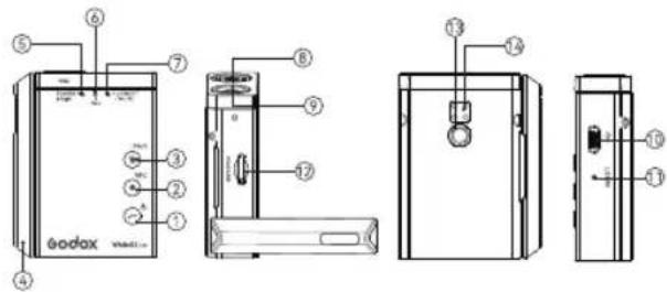
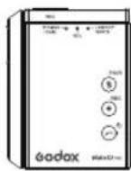
Body-pack Transmitter (WMicS2 TX2)
text_image
Technical diagram of an eodox washing machine with labeled components and internal wiring- Power Switch/Loocut Button
- Record Button
- Mute/Pair Button
- Antenna
- Power Switch/Pair Indicator
- Record Indicator
- Lowcut/Mute Indicator
-
Built-in Mic
-
Mic Input Port
- Type-C Data Transmitting/Charging Port
- Reset Hole
- SD Card Slot
- 1/4" Coldshoe Mount Port
- Charging Points
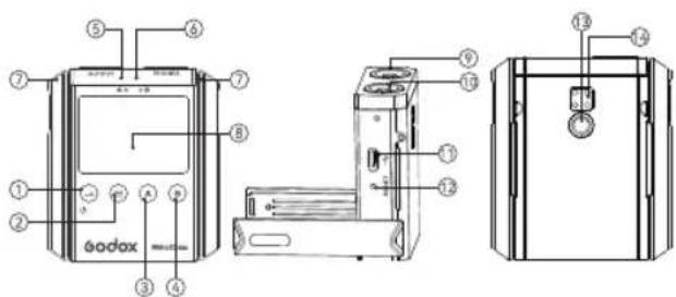
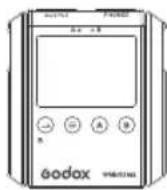
Portable Receiver (WMicS2 RX2)
text_image
Technical diagram of a bodax device with numbered components and labeled parts- Power Switch Button
- Function/Confirm Button
- A Group Button
- B Group Button
- A Group Indicator
- B Group Indicator
- Antenna
-
OLED Display
-
3.5mm Audio Output Port
- 3.5mm Earphone Monitoring Port
- Type-C Data Transmitting/Charging Port
- Reset Hole
- 1/4" Coldshoe Mount Port
- Charging Points
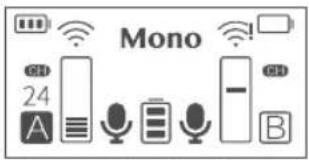
OLED Display:
- Mono/Stereo Mode
- Receiver Battery Level Indicator
- A/B Group Frequency Signal (! indicates Disconnection)
- A/B Transmitter Battery Level Indicator
- A/B Transmitter Input Volume
- A/B Group Channel 01-48
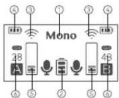
text_image
Mono 2B A 3B 4BUHF Charging Case (WM-C)
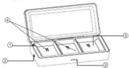
text_image
Technical diagram of a toolbox with labeled parts and internal compartments-
Pair Button
-
Type-C Charging Port
-
Power Indicators
-
Transmitter Slot
-
Receiver Slot
Included Items
① Body-pack Transmitter (WMicS2 TX2)
② Portable Receiver (WMicS2 RX2)
natural_image
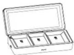
Line drawing of an open cylindrical container with compartments labeled '甲', '乙', '丙' (no text or symbols on the main body)③ UHF Charging Case (WM-C)
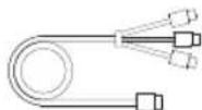
④ Type-C to USB Cable
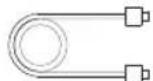
⑤ Type-C to USB Cable
| Name | Model | Included Items |
| Body-pack Transmitter | WMicS2 TX2 | 1×1, 5×1, 7×1, 8×1,9×1, 12×1, 15×1 |
| Portable Receiver | WMicS2 RX2 | 2×1, 5×1, 8×1, 9×1,10×1, 11×1, 15×1 |
| UHF Charging Case | WM-C | 3×1, 5×1, 13×1, 15×1 |
| UHF Compact Wireless Microphone System Kit1 | WMicS2 Kit 1 | 1×1, 2×1, 4×1, 6×1,7×1, 8×2, 9×2, 10×1,11×1, 12×1, 14×1, 15×1 |
| UHF Compact Wireless Microphone System Kit2 | WMicS2 Kit 2 | 1×2, 2×1, 3×1, 4×1,6×1, 7×2, 8×3, 9×3,10×1, 11×1, 12×2, 13×1,15×1 |
Operation Instruction
Body-pack Transmitter
1.Power Switch
Long press the Power Switch/Lowcut Button to power on or off the transmitter, the Power Switch/Pair Indicator will be constant on green after turned on.
2.Lowcut
Short press the Power Switch/Lowcut Button to turn on lowcut function, the Lowcut/Mute Indicator will be constant on yellow.
3.Recording Backup
Insert an external TF card into the transmitter, short press the Record Button to enter recording mode, the audio files will be automatically backed up and the Record Indicator will be constant on red. Short press the Record Button again to stop recording, then the Record Indicator will be off. Connect it to the computer with Type-C data cable, short press the Power Switch/Lowcut Button to enter the computer storage mode, user can play back and monitor the recorded audio files.
Note: The recorded audio files are in WAV format, and there will be one file stored when the recording function is triggered once.
Recorded files storage rules: The default duration of an audio
files is 30 minutes. In case of less than 30 minutes, it will still be stored as one file. If it exceeds 30 minutes, the exceeded part will automatically be stored as another file.
4.Mute
Short press the Mute/Pair Button to switch to mute mode, the Lowcut/Mute Indicator will be constant on red, the receiver's OLED display shows mute icon, short press it again to exit mute mode.
5.Pair
Long press the Mute/Pair Button for 3 seconds, the receiver's OLED display shows "Matching", then the transmitter starts matching, the Power Switch/Pair Indicator blinks blue and yellow, turns to be constant on green after pair success.
6. Computer-triggered Storage
Short press the Power Switch/Lowcut Button after connecting to the computer with red port of Type-C data cable, the computer will recognize the storage function and eject the U disk.
7. Charging through Type-C port
When charging through Type-C data cable, the Power Switch/Pair Indicator will be constant on yellow in power on status, while blinks red and then constant on blue after fully charged in power off status.
Note: The transmitter works normally during charging without affecting the recording backup. USB file reading and writing is not available when recording or synchronizing audio with mobile phone. Connect to the computer through USB port can only charge the transmitter, but the U disk file will not appear in the computer file management until exiting recording or synchronizing audio with mobile phone.
8. Indicator Instruction
8.1 The Power Switch/Pair Indicator will be constant on green when it is powered on but unpaired.
8.2 The Power Switch/Pair Indicator will blink blue and yellow during pairing, and turn to be constant on green after pairing success.
8.3 The Record Indicator will be constant on red when recording, and off when stop recording.
8.4 The Lowcut/Mute Indicator will be constant on red in mute mode.
8.5 The Lowcut/Mute Indicator will be constant on yellow in lowcut mode.
8.6 Indicator status when the transmitter battery is lower than 10%;
8.6.1 When the pairing is successful/unsuccessful, the Power Switch/Pair Indicator will be constant on red.
8.6.2 Record when pairing is successful/unsuccessful, the Power Switch/Pair Indicator and the Record Indicator will be constant on red.
8.6.3 Record and turn on the lowcut function when the pairing is successful/unsuccessful, the Power Switch/Pair Indicator and the Record Indicator will be constant on red, and the Lowcut/Mute Indicator will be constant on yellow.
8.6.4 Record and mute when pairing is successful/unsuccessful, the Power Switch/Pair Indicator, Record Indicator and Lowcut/Mute Indicator will be constant on red.
8.7 Indicator status when plugging in the power adapter:
8.7.1 The Power Switch/Pair Indicator will be constant on yellow when charging in power on status, while blinks red when charging in power off status, and turn off after fully charged.
8.7.2 Record in power on status, the Power Switch/Pair Indicator will be constant on yellow, and the Record Indicator will be constant on red.
8.7.3 Record and turn on the lowcut function in power on status, the Power Switch/Pair Indicator will be constant on yellow, the Record Indicator will be constant on red, and the Lowcut/Mute Indicator will be constant on yellow.
8.7.4 Record and mute in power on status, the Power Switch/Pair Indicator will be constant on yellow, the Record Indicator and Lowcut/Mute Indicator will be constant on red.
Portable Receiver (WMicS2 RX2)
1. Power Switch
Long press the Power Switch Button for 2 seconds to power on/off, the OLED display will light on.
2. Language Setting
The receiver will automatically enter the language setting interface when turned on for the first time, short press the A/B Group Button to enter language selection, short press the Function/Confirm Button to confirm the language, it will automatically show the saved language afterwards. Press and hold the A/B Group Button for 4 seconds at the same time to automatically reset and clear the original data, then it will automatically enter the language setting interface after restarting.
3.Pairing
Long press the A/B Group Button for 2 seconds, the A/B icon blinks in dashed box on the OLED display, it will automatically recognize transmitters and start pairing with "pairing" appears on the display. If the
text_image
Mono 24 A B(group A is paired and group B is unpaired)
Pairing is successful, "Pairing ok" appears on the display and returns to the main interface, then the A/B Group Indicator be constant on green, A/B Transmitter Battery Level Indicator displays the real-time battery level, channel No. displays under the "CH" icon, A/B Group
A/B Group icon turns into solid box, A/B Transmitter Input Volume icon displays real-time volume. If the Pairing is unsuccessful, "Pairing fail" appears on the display and returns to the main interface.
4.Channel Setting
Short press the A/B Group Button, the display shows the A/B group channel No. (01-48), long press the A/B Group Button to make the adjusted channel No. blinks, then short press the A Group Button can decrease channel No., while short press the B Group Button can increase channel No., finally short press the Function/Confirm Button to confirm the channel setting.

5.Volume Setting
Short press the A/B Group Button, the display shows the volume No. of A/B group (01-10), long press the A/B Group Button to make the adjusted No. blinks, then short

press the A Group Button can decrease the volume, while short press the B Group Button can increase the volume, finally short press the Function/Confirm Button to confirm the volume setting.
6. Output Mode Setting
Short press the A/B Group Button, the display shows the output mode (Mono/ Stereo), long press the Function/Confirm Button to make the yellow icon blinks, then short press the A/B Group Button to switch between mono and stereo mode, finally short press the Function/Confirm Button to confirm the output mode setting. Short press the A/B Group Button at the same time on the main interface can also switch between mono and stereo mode.
7.OLED Light Setting
Short press the A/B Group Button, the display shows the OLED light (1-8), long press the Function/Confirm Button to make
Output Mode
Mono
OLED Light
4
the number blinks, then short press the A Group Button can decrease the light, short press the B Group Button can increase the light, finally short press the Function/Confirm Button to confirm the light setting.
8.Screen Dormancy
Short press the A/B Group Button, the display shows the screen dormancy time (10S/30S/60S), long press the Function/Confirm Button to make the number blinks, then short press the A Group Button can decrease the screen dormancy time, short press the B Group Button can increase the screen dormancy time, finally short press the Function/Confirm Button to confirm the screen dormancy setting.
Screen Dormancy
10_s
9.Screen Rotate
Long press the Function/Confirm Button can rotate the screen.
10. Indicator Instruction
The OLED display will light on after powered on. If the A/B group is
paired successfully, the corresponding indicator will be constant on green, and turn off after disconnected.
UHF Charging Case (WM-C)
1. Pair Button
The transmitter/receiver will enter deep sleep after fully charged for one day, and cannot be turned on when you pick it up, it needs to be put into the charging case and press the Pair Button to wake up. Long press the Pair Button for 3 seconds, the transmitter/receiver will automatically start pairing.
2.Power Indicators (4)
Self-charging: the Power Indicators will blink green increasingly, and all be constant on green after fully charged.
Charging the transmitter/receiver: the Power Indicators will be constant on green when charging the transmitter/receiver, decreasing along with its battery level.
Installation Instruction
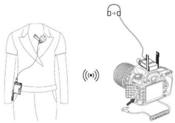
natural_image
Line drawing of a person wearing a suit with a device, alongside a simplified camera setup showing signal waves (no text or symbols)
natural_image
Line drawing of a person wearing a blazer and pants (no text or symbols)((•))
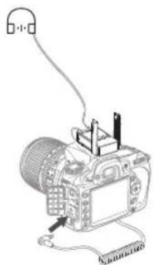
natural_image
Diagram of a DSLR camera with attached cable and earphones, no text or symbols presentTransmitter
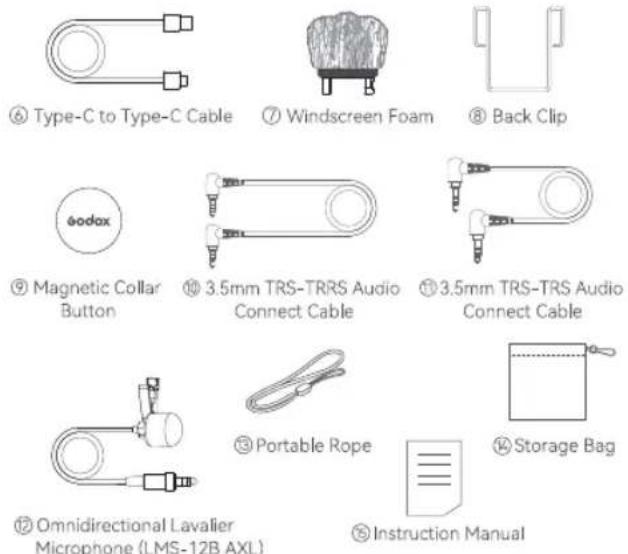
① Insert the omnidirectional lavalier microphone into the transmitter's MIC port.
② Turn on the transmitter to set the relevant parameters.
③ Clip the transmitter onto the belt, collar, sleeve or put it into your pocket.
Note: When clipping the transmitter on the collar with magnetic collar button, you can speak directly at the built-in mic without using the omnidirectional lavalier microphone.
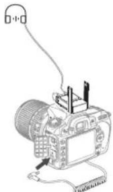
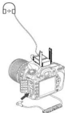
Receiver
① Connect the 1/4" cold shoe onto the receiver, and install them on the camera or shooting equipment.
② Insert one end of the 3.5mm cable into the receiver's OUTPUT port and the other end into camera's MIC port.
③ Turn on the transmitter to set the relevant parameters.
Note: Please set the group and channels of transmitter and receiver to the same when setting parameters. When a receiver is connecting to two transmitters, A transmitter must be set and used in A group while B transmitter must be set and used in B group.
Technical Data
| Product Name | Body-pack Transmitter | Portable Receiver | UHF Charging Case |
| Model | WMicS2 TX2 | WMicS2 RX2 | WM-C |
| Group | A/B | A/B | / |
| Channel | 96(Group A: 48; Group B: 48) | 96(Group A: 48; Group B: 48) | / |
| RF Frequency Range | 514.56MHz-553.92MHz | 514.56MHz-553.92MHz | / |
| Audio Frequency Range | 40Hz-18KHz | 40Hz-18KHz | / |
| Sound Delay | 12ms | / | |
| Audio Input Port | 3.5mm | 12ms | / |
| Lithium Battery Capacity | 770mAh | 3.5mm770mAh | 10000mAh |
| Type-C Input Parameters | 5V/0.4A | 5V/2A(Max.) |
| Working Temperature Range | -10°C~45°C | -10°C~45°C | -10°C~45°C |
| Receiving Distance | Barrier-free receiving distance: 200m, Barriered receiving distance: 60m | Barrier-free receiving distance: 200m, Barriered receiving distance: 60m | / / |
| Signal Noise Ratio | =70dB | =70dB | |
| Receive Sensitivity | / | -95dBm | / |
| Distortion | / | Below 3% | / |
| Dimension | 65.8X50.4X20.5mm (Antenna length: 65mm) | 65.8X58.4X20.5mm (Antenna length: 65mm) | 185.8X84.2 x42mm |
| Net Weight | 57g | 66g | 367g |
- Specifications and data may subject to changes without notice.
Troubleshooting
- Unable to receive audio signal. Make sure batteries are installed correctly and Power Switch is turned on. Check if the transmitter and the receiver are set to the same channel, if the microphone or earphone is well connected, or if the devices are set to the correct mode.
- Check if the transmitter is set to mute mode or not.
- Signal disturbance or shooting interference. Change a different channel of the transmitter and receiver.
- Operating audio distance limited or signal missing. Check if batteries are exhausted. If so, replace them.
Maintenance
- Avoid sudden drops. The device may fail to work after strong shocks, impacts, or excess stress.
- Keep dry. The product isn't water-proof. Malfunction, rust, and corrosion may occur and go beyond repair if soaked in water or exposed to high humidity.
- Avoid sudden temperature changes. Condensation happens if sudden temperature changes such as the circumstance when taking the transmitter and receiver out of a building with higher temperature to outside in winter. Please put the transmitter and receiver in a handbag or plastic bag beforehand.
- Keep away from strong magnetic field. The strong static or magnetic field produced by devices such as radio transmitters leads to malfunction.
- Unauthorized service will void the warranty.
- If the product had failures or was wetted, do not use it until it is repaired by professionals.
- Changes made to the specifications or designs may not be reflected in this manual.
FCC Caution
This device complies with part 15 of the FCC Rules. Operation is subject to the following two conditions:
(1) This device may not cause harmful interference, and
(2) this device must accept any interference received, including interference that may cause undesired operation.
Any Changes or modifications not expressly approved by the party responsible for compliance could void the user's authority to operate the equipment.
Note: This equipment has been tested and found to comply with the limits for a Class B digital device, pursuant to part 15 of the FCC Rules. These limits are designed to provide reasonable protection against harmful interference in a residential installation. This equipment generates uses and can radiate radio frequency energy and, if not installed and used in accordance with the instructions, may cause harmful interference to radio communications. However, there is no guarantee that interference will not occur in a particular installation. If this equipment does cause harmful interference to radio or television
reception, which can be determined by turning the equipment off and on, the user is encouraged to try to correct the interference by one or more of the following measures:
-Reorient or relocate the receiving antenna.
-Increase the separation between the equipment and receiver.
-Connect the equipment into an outlet on a circuit different from that to which the receiver is connected.
-Consult the dealer or an experienced radio/TV technician for help.
The device has been evaluated to meet general RF exposure requirement.
The device can be used in portable exposure condition without restriction.
Warning
Operating frequency: 514.56MHz-553.92MHz Maximum ERP Power: -9.45dBm
Declaration of Conformity:
GODOX Photo Equipment Co., Ltd. hereby declares that this equipment are in compliance with the essential requirements and other relevant provisions of Directive 2014/53/EU. In accordance with Article 10(2) and Article 10(10), this product is allowed to be used in all EU member states. For more information of DoC, Please click this web link: https://www.godox.com/DOC/Godox_WMicS2_Series_DOC.pdf. The device complies with RF specifications when the device used at 0mm from your body.
产品保修
Dear customers, as this warranty card is an important certificate to apply for our maintenance service, please fill in the following form in coordination with the seller and safe-keep it. Thank you!
| Product Information | Model | Product Code Number |
| Customer Information | Name | Contact Number |
| Address | ||
| Seller Information | Name | |
| Contact Number | ||
| Address | ||
| Date of Sale | ||
| Note: | ||
Note: This form shall be sealed by the seller.
Applicable Products
The document applies to the products listed on the Product Maintenance Information (see below for further information). Other products or accessories (e.g. promotional items, giveaways and additional accessories attached, etc.) are not included in this warranty scope.
Warranty Period
The warranty period of products and accessories is implemented according to the relevant Product Maintenance Information. The warranty period is calculated from the day(purchase date) when the product is bought for the first time, And the purchase date is considered as the date registered on the warranty card when buying the product.
How to Get the Maintenance Service
If maintenance service is needed, you can directly contact the product distributor or authorized service institutions. You can also contact the Godox after-sale service call and we will offer you service. When applying for maintenance service, you should provide valid warranty
card. If you cannot provide valid warranty card, we may offer you maintenance service once confirmed that the product or accessory is involved in the maintenance scope, but that shall not be considered as our obligation.
Inapplicable Cases
The guarantee and service offered by this document are not applicable in the following cases: ①. The product or accessory has expired its warranty period; ②. Breakage or damage caused by inappropriate usage, maintenance or preservation, such as improper packing, improper usage, improper plugging in/out external equipment, falling off or squeezing by external force, contacting or exposing to the improper temperature, solvent, acid, base, flooding and damp environments, etc; ③. Breakage or damage caused by non-authorized institution or staff in the process of installation, maintenance, alternation, addition and detachment; ④. The original identifying information of product or accessory is modified, alternated, or removed; ⑤. No valid warranty card; ⑥. Breakage or damage caused by using illegally authorized, nonstandard or non-public released software; ⑦. Breakage or damage caused by force majeure or accident; ⑧. Breakage or damage that could not be attributed to the product itself. Once met these situations above, you should seek
solutions from the related responsible parties and Godox assumes no responsibility. The damage caused by parts, accessories and software that beyond the warranty period or scope is not included in our maintenance scope. The normal discoloration, abrasion and consumption are not the breakage within the maintenance scope
Maintenance and Service Support Information
The warranty period and service types of products are implemented according to the following
Product Maintenance Information:
| Product Type | Name | Maintenance Period (month) | Warranty Service Type |
| Parts | Circuit Board | 12 | Customer sends the product to designated site |
| Battery | 3 | ||
| Charger, Electrical Parts etc. | 12 | ||
| Other Items | Battery Case, Windscreen Foam,Wind Cap, Locking Device,Lanyard, Tie. | NO | Without warranty |
Godox After-sale Service Call: 0755-29609320-8062