
SpinStand - Storage furniture Andover - Free user manual and instructions
Find the device manual for free SpinStand Andover in PDF.

| Product Type | Rotating Display Stand |
| Brand | Andover |
| Model | SpinStand |
| Rotation | 360 degrees smooth rotation |
| Material | High-density plastic with anti-slip rubber base |
| Dimensions | 12 x 12 x 2 inches (30 x 30 x 5 cm) |
| Weight Capacity | Up to 22 lbs (10 kg) |
| Net Weight | 1.5 lbs (0.68 kg) |
| Power Source | None (manual rotation) |
| Primary Function | Display and rotate items for easy viewing |
| Usage | Indoor use for retail displays, home decor, or crafts |
| Maintenance | Wipe with a damp cloth; avoid abrasive cleaners |
| Cleaning Instructions | Use mild soap and water; dry thoroughly |
| Safety Features | Non-slip base for stability |
| Spare Parts Availability | Not applicable (no moving parts) |
| Repairability | Not repairable; replace if damaged |
| Warranty | 1 year limited warranty |
| Package Contents | 1 x SpinStand, 1 x User Manual |
Frequently Asked Questions - SpinStand Andover
User questions about SpinStand Andover
0 question about this device. Answer the ones you know or ask your own.
Ask a new question about this device
Download the instructions for your Storage furniture in PDF format for free! Find your manual SpinStand - Andover and take your electronic device back in hand. On this page are published all the documents necessary for the use of your device. SpinStand by Andover.
USER MANUAL SpinStand Andover
natural_image
Line drawing of a multi-tiered rectangular metal frame structure with mounting feet (no text or symbols)
andover
www.andoveraudio.com
Table of Contents
Introduction......4
In the Box....5
Assembly....6-9
Anti-Tip Kit....10
Warranty and Service....11
Introduction
We're really pleased that you have chosen Spinstand. Spinstand is perfectly matched to Spinbase, but may also be used with the Andover Model-One, or any audio component smaller than 18" x 13.5" on the top shelf. It will provide a solid and stable platform suitable for vinyl record playback.
Spinstand will accommodate up to approximately 150 records on its two lower Melamine shelves. (Actual number will be less for double records or those with gatefold covers)
You may assemble Spinstand with either three or four shelves in case you prefer the lower profile or you do not require the additional shelf for accessories.
About Andover Audio
Since 2012, Andover Audio has provided behind the scenes design and manufacturing services to some of the most respected brands in automotive, professional, and high-performance consumer audio. We now focus our award-winning skills on our own product line that artfully blends exceptional sound with distinctive design.

In The Box
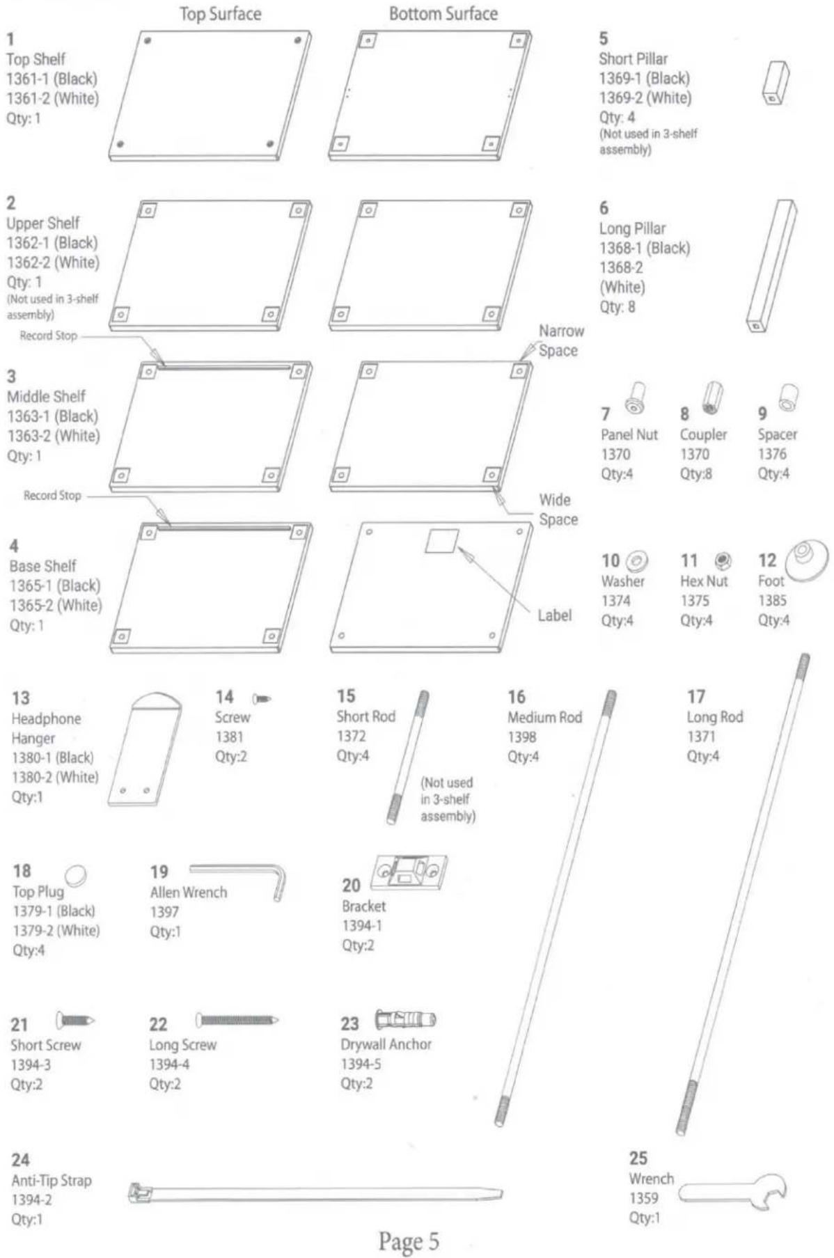
5
Short Pillar
1369-1 (Black)
1369-2 (White)
Qty: 4
(Not used in 3-shelf assembly)
7
Panel Nut
1370
Qty:4
8
Coupler
1370
Qty:8
9
Spacer
1376
Qty:4
10 11 12 Washer Hex Nut Foot 1374 1375 1385 Qty:4 Qty:4 Qty:4
23
Drywall Anchor
1394-5
Qty:2
Assembly
-
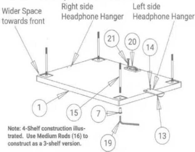
Locate the Top Shelf (Item 1) and place it top-down on a soft surface. The holes in the corners of the shelf are closer to the back edge than to the front edge. Orient the top shelf so that the wider border (Front) is towards you.
-
Install the Headphone Hanger (Item 13) using the two screws (Item 14). Align the Headphone hanger with the pilot holes corresponding to the side of the stand you prefer to hang your headphones. You may omit this step if you don't need the hanger.
-
Install one of the Anti-Tip brackets (Item 20) to the Top Shelf using two of the Short Screws (Item 21). The Bracket may be shipped with the Strap (Item 24) attached. Press the small tab near the latch to release the strap from the bracket.
-
Place a panel nut (Item 7) in each of the four corners facing upwards as shown in the diagram.
-
Attach a Threaded Rod onto each of the four Panel Nuts and tighten firmly using the Allen Wrench supplied (Item 19). For the typical 4-shelf assembly, use the Short Rods (Item 15). If you prefer the 3-shelf option, use the Medium Rods (Item 16), and proceed directly to Step 9.
-
Attach a Coupler (Item 8) to each of the four Threaded Rods.
-
Attach a Medium Rod (Item 16) to each of the couplers. Tighten firmly by hand.
-
Slide a Short Pillar (Item 5) over each rod assembly and carefully align the pillar in the square recess cut in the shelf.
-
Slide the Upper Shelf (Item 2) over the threaded rods making sure the edge with the wider spacing between the holes and the edge is towards the front, just as you did with the Top Shelf.

Assembly - Cont.
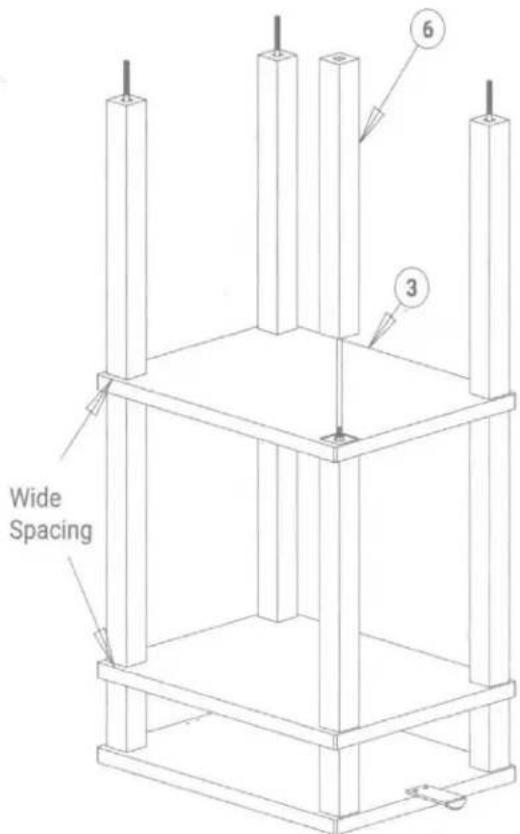
- Slide the Middle Shelf (Item 3) over the threaded rods making sure the edge with the wider spacing between the holes and edge is towards the front, just as you did with the Top Shelf. The shelf should be oriended with the top down. The Record Stop should be facing down and along the back.
- Slide the remaining Long Pillars (Item 6) over each rod assembly and carefully align each pillar in the square recess cut in the shelf.
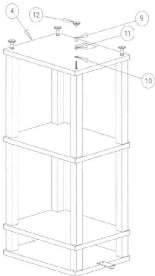
- Slide the Base Shelf (Item 4) in position over the four rods. The Label should be facing up and towards the rear of the shelf.
- Place a Washer (Item 10) on each rod, followed by a Hex Nut (Item 11). Snug it up but don't tighten it.
- Carefully align each Pillar such that they fit securely into the mating recesses in the shelves. Once everything is aligned, tighten the nuts firmly using the supplied wrench (Item 25). Hold the panel nuts (Item 7) with the Allen Wrench (Item 19). Important: Make sure all the pillars are correctly aligned with the square pockets in the shelves or the stand will be uneven.
- Slip a spacer (Item 9) over each rod, then screw a foot (Item 12) over each rod and twist it finger-tight against the spacer.
Assembly - Cont.
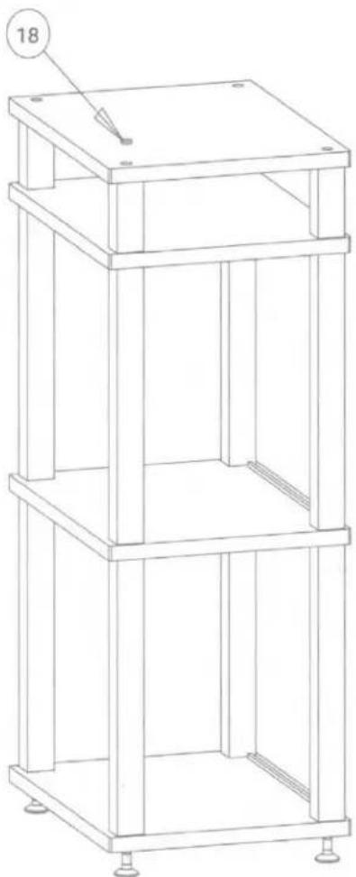
- Turn the completed stand upright. Insert the four Top Plugs (Item 18) into the four corner holes to conceal the hardware.
- Place the Spinstand into position. Adjust the feet to assure that the stand is level and stable.
natural_image
Technical line drawing of a multi-tiered vertical shelf or rack structure with mounting feet (no text or symbols)Anti-Tip Kit installation
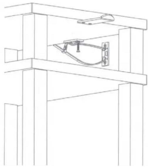
IMPORTANT NOTE: An Anti-Tip Strap is included with your Spinstand. Please use it whenever Spinstand is installed in a location where it may tip and cause physical harm. Drywall inserts (Item 23) and screws (Item 22) are included with this kit, but may not be suitable for every type of wall. It is your responsibility to supply wall mounting hardware suitable for the specific wall construction of your home. It is best to locate the Spinstand such that the Anti-Tip bracket may be screwed directly into a wall stud whenever possible.
-
Once Spinstand is in position, locate the second Bracket (Item 20) at the approximate height of the top shelf and centered relative to the stand. Mark the location of the two screw holes with a pencil.
-
Drill suitable pilot holes for your preferred wall anchors at the marked positions. If you use the anchors we supply, use 1/4" drill bit. Install the anchors and attach the remaining bracket. Anchors are not needed if the bracket can be attached to a stud. An 1/8" drill should be used for pilot holes in a stud.
-
Loop the Anti-Tip strap (Item 24) through both brackets and insert the tip of the strap through the latching end, forming a closed loop. Check to make sure the latch is secure and will not slip open.
natural_image
Technical line drawing of a structural frame with a central mechanical component (no text or symbols)Two-Year Limited Warranty
Andover Audio warrants your product against manufacturing defects and workmanship to the initial purchaser for a period of two (2) years from the date of delivery to customer. Andover Audio will repair or replace the unit as necessary to restore proper operation. This warranty covers both parts and labor for the warranty period. The warranty excludes physical damage caused by accident or abuse outside of our control, or if the unit is damaged due to incorrect packing. The warranty also excludes normal wear items. If you think you need warranty service, please contact us to obtain an RMA (Return Merchandise Authorization) by e-mailing support@andoveraudio.com or calling 978.775.3670. For more information on returns and exchanges, please visit www.andoveraudio.com/pages/returns-and-exchanges. If your unit was purchased from a local dealer, contact them first. They may be able to resolve some issues without requiring a return.
Service
Should you encounter a problem that you are unable to solve, please contact customer service at support@andoveraudio.com, or the dealer that sold you your unit. If you must return your unit for any reason, it must be safely packed and shipped in its original carton and packing material. Damage that is the result of improper packaging is not covered by the warranty.
Andover Audio, L.L.C.
15 High Street North Andover, Massachusetts 01845
www.andoveraudio.com | support@andoveraudio.com | 978.775.3670
Andover is a trademark of Andover Audio L.L.C.
Andover Audio subscribes to a program of continuous improvement. As a result, some product features and characteristics may change without prior notice.

Brand : Andover
Model : SpinStand
Category : Storage furniture