
AMP7502 - Receiver BLAUPUNKT - Free user manual and instructions
Find the device manual for free AMP7502 BLAUPUNKT in PDF.
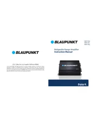


| Product Type | Car Stereo Receiver |
| Brand | Blaupunkt |
| Model | AMP7502 |
| Form Factor | 1-DIN |
| Dimensions (W x H x D) | 178 x 50 x 168 mm |
| Weight | 1.5 kg |
| Power Supply | 12V DC (negative ground) |
| Peak Power Output | 4 x 50 W |
| RMS Power Output | 4 x 20 W |
| Tuner Bands | AM / FM |
| Playback Media | CD, CD-R, CD-RW |
| Audio Formats | MP3, WMA |
| Inputs | AUX (front 3.5 mm), USB |
| Outputs | 4 x Speaker, Pre-amp (RCA) |
| Bluetooth | No |
| Display | LCD with backlight |
| Remote Control | Included (wired or IR?) |
| Safety | Install by professional; disconnect battery before wiring |
| Maintenance | Clean with soft dry cloth; avoid liquids |
| Spare Parts & Repairability | Contact Blaupunkt service center for parts |
Frequently Asked Questions - AMP7502 BLAUPUNKT
User questions about AMP7502 BLAUPUNKT
0 question about this device. Answer the ones you know or ask your own.
Ask a new question about this device
Download the instructions for your Receiver in PDF format for free! Find your manual AMP7502 - BLAUPUNKT and take your electronic device back in hand. On this page are published all the documents necessary for the use of your device. AMP7502 by BLAUPUNKT.
USER MANUAL AMP7502 BLAUPUNKT
©2017 BLAUPUNKT. All Rights Reserved. This device complies with part 15 of the FCC Rules. Operation is subject to the following two conditions: (1) this device may not cause harmful interference, and (2) this device must accept any interference received, including interference that may cause undesired operation. WARNING: This product contains a chemical known to the State of California to cause cancer and reproductive toxicity.

BLAUPUNKT
AMP1504
AMP1501
AMP7502
Bridgeable Range Amplifier Instruction Manual

Enjoy it.
System Planning
Proper system planning is the best way to maximize your amplifier's performance. By planning your installation carefully, you can avoid situations where the performance and reliability of your system is compromised. Our authorized dealer has been trained to maximize your system's sound quality when installing the amplifier, and is a valuable resource in helping you with your system's design and installation.
Speaker Requirements
Each channel of your amplifier can easily handle 4 Ω speaker loads when used in Stereo Mode. When a channel-pair is bridged, the recommended minimum load impedance is 3Ω for subwoofer use, and 4Ω for full range operation. Although operation with lower impedances is not likely to cause immediate damage to the internal circuitry, the unit will most likely overheat, causing the thermal protection circuitry to shut down the amplifier. When the chassis cools down, normal operation will resume.
Continuing to operate the amplifier under these conditions is not recommended and will reduce its life expectancy. Most speakers designed for car audio operation are 4Ω impedance. Connecting two such speakers in parallel will result in a 2Ω nominal impedance, which is not recommended for use with bridged channels of your amplifier.


| Symptom Possible Cause | Action to take | |
| Poor bass response Speakers wired wrong polarity causing cancellation at low frequencies | Check speaker polarity and repair as needed | |
| Crossover set incorrectly Reset crossover referring to the multi-cross crossover configuration section of this manual for detailed instructions | ||
| Battery fuse blowing | Impedance load to amplifier too low | Check speaker impedance load. If below 2Ω stereo or 4Ω mono, rewire speakers to achieve a higher impedance |
| Short in power wire or incorrect power connections | Check power and ground connections and repair as needed | |
| Fuse used is smaller and recommended | Replace with proper fuse size | |
| Too much current being drawn | Check speaker impedance load. If below 2Ω stereo or 4Ω mono, rewire speakers to achieve a higher impedance and replace with recommended fuse size | |
| Short in power wire or incorrect wire | Check power and ground connection and repair as needed | |
| Amplifier fuse blowing | Too much current being drawn | Check speaker impedance load. If below 2Ω stereo or 4Ω mono, rewire speakers to achieve a higher impedance and replace with recommended fuse size |
| Check power and ground connections. Repair as needed | ||
| Fuse used is smaller than recommended | Replace with proper fuse size | |
Trouble Shooting
| Symptom Possible Cause | Action to take | |
| No output Low or no remote | turn-on input | Check remote turn-on voltage output on amplifier and correct as needed |
| Fuse down | Check power wire integrity and reverse polarity, repair as needed and replace fuse | |
| Power wires not connected Check power wire connections and repair/replace as needed | ||
| Audio input not connected or no output from source | Check input connections and signal integrity repair/replace as needed | |
| Speaker wires not connected | Check speaker wires and repair/replace as needed | |
| Audio cycles on and off | Speakers are blown | Check system with known working speaker and repair/replace speakers as needed |
| Thermal protection engages when amplifier heat sink temperature exceeds 90°C | Make sure there is proper ventilation for amplifier and improve ventilation as needed | |
| Loose or poor audio input | Check Input connections and repair/replace as needed | |
| Distorted output | Amplifier level sensitivity set too high, exceeding maximum output capability of amplifier | Reset gain. Refer to the turning section of the manual for detailed instructions |
| Impedance load to amplifier too low | Check speaker impedance load. If below 2Ω stereo or 4Ω mono, rewire speakers to achieve a higher impedance | |
| Shorted speaker wires Check speaker wire connections and repair/replace as needed | ||
| Speaker incorrectly connected to amplifier properly | Check speaker wiring and repair/replace as needed. Refer to the installation section of this manual for detailed instructions | |
| Speakers are blown Check system with known working speaker and repair/replace as needed | ||
Connection Diagram

WARNING
Before beginning, DO NOT connect the car battery's negative poles to the positive poles. The short-circuitry might cause damage to your amplifier and other electrical parts in the car.
System 1: 2-Channel Mode

System 2: Connection Subwoofer
Specifications
AMP1501
| RMS output power 4Ω (Watts) | 330W x 1CH (THD 2%) |
| RMS output power 2Ω (Watts) | 563W x 1 CH |
| THD | <=0.05% |
| Frequency response (±2dB) | 10Hz ~300Hz |
| Signal to noise ratio | =>90dB |
| Sensitivity | 100mV~6V |
| Recommended fuse type | 20A x 2 |
| Dimensions | 180 x 190 x 53 mm |
System 1: Connection Subwoofer

System 2: Bridge Connection Subwoofer
Specifications
AMP7502
| RMS output power 4Ω (Watts) | 160W x 1CH |
| RMS output power 2Ω (Watts) | 325W x 2 CH |
| RMS bridged output power 4Ω (Watts) | 330W x 2 CH(THD 1%) |
| THD | <=0.05% |
| Frequency response (±2dB) | 10Hz ~45KHz |
| Signal to noise ratio | =>90dB |
| Sensitivity | 150mV~6V |
| Recommended fuse type | 30A x 1 |
| Dimensions | 220 x 190 x 53 mm |
System 1: 4-Channel Mode

System 2: Bridge Connection Subwoofer
Specifications
AMP1504
| RMS output power 4Ω (Watts) | 150W x 4CH |
| RMS output power 2Ω (Watts) | 300W x 4 CH |
| RMS bridged output power 4Ω (Watts) | 1500W x 2CH |
| THD | <=0.05% |
| Frequency response (±2dB) | 10Hz ~45KHz |
| Signal to noise ratio | =>90dB |
| Sensitivity | 150mV~6V |
| Recommended fuse type | 30A x 2 |
| Dimensions | 300 x 190 x 53 mm |
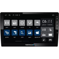
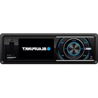
Brand : BLAUPUNKT
Model : AMP7502
Category : Receiver