MWB-10-VUE - Screen Mimo Monitors - Free user manual and instructions
Find the device manual for free MWB-10-VUE Mimo Monitors in PDF.

User questions about MWB-10-VUE Mimo Monitors
0 question about this device. Answer the ones you know or ask your own.
Ask a new question about this device
Download the instructions for your Screen in PDF format for free! Find your manual MWB-10-VUE - Mimo Monitors and take your electronic device back in hand. On this page are published all the documents necessary for the use of your device. MWB-10-VUE by Mimo Monitors.
USER MANUAL MWB-10-VUE Mimo Monitors
7", 10.1" and 15.6" Tablet and 10.1" Vue Wall Box Installation Manual
MWB-7-MCT/MWB-10-MCT/MWB-156-MCT/MWB-10-VUE/MWB-10-BSBI
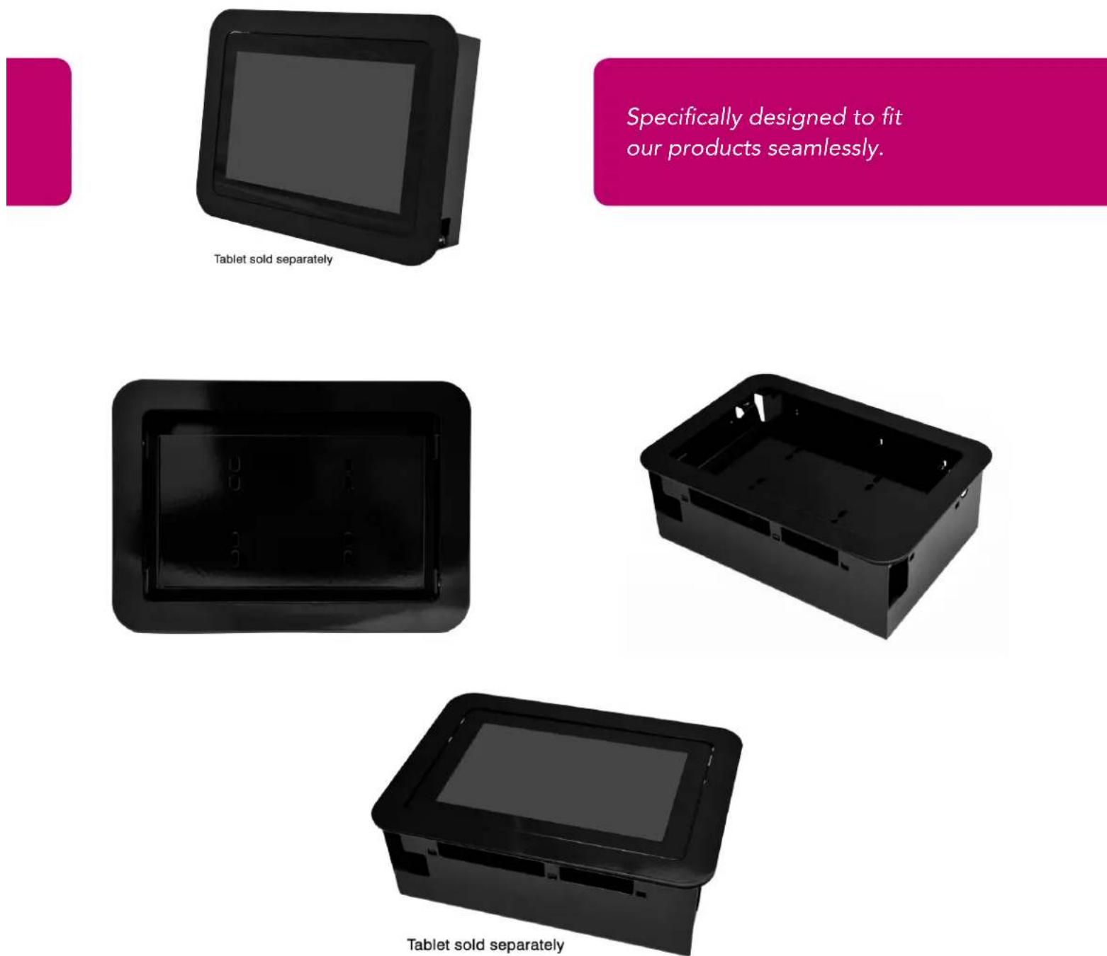
Specifically designed to fit our products seamlessly.
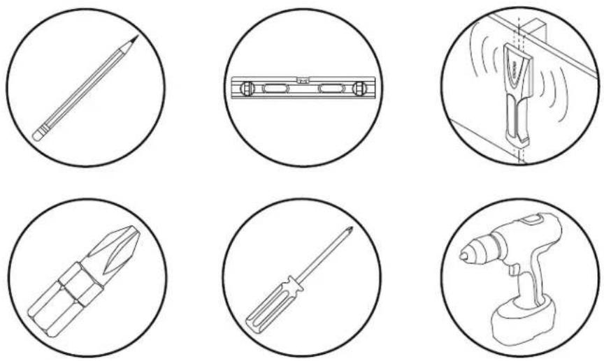
Tools
Parts (Before beginning, make sure you have all parts shown below)
| Parts List | |
| ytG | |
| A xob llaw-ni | 1 |
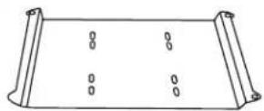
| B Tablet/Display Mounting Plate | 1 |
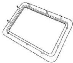
| C Front Bezel | 1 |
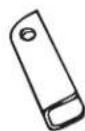
| D Dry Wall Clips (Installed) | 4 |
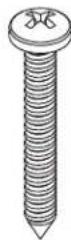
| E Dry Wall Clip Screws (Installed) | 4 |
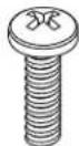
| F M4 x 6mm Screws | 8 |
B (4) Mounting Plate ytQnoitpircseD
C (2) Front Bezel
natural_image
Line drawing of a rectangular frame with mounting holes and a central rectangular cutout (no text or symbols)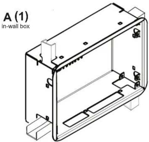
natural_image
Technical line drawing of an in-wall box housing with internal components (no text or symbols)D (2) Drywall Clips
E (2) Screws
F (2) Screws
natural_image
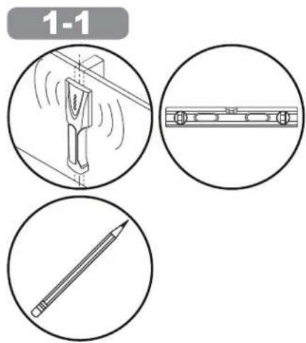
Isometric line drawing of a mechanical device inside a structural frame, with no visible text or symbols.Use Stud Finder to locate and mark edge of studs.
1-2a
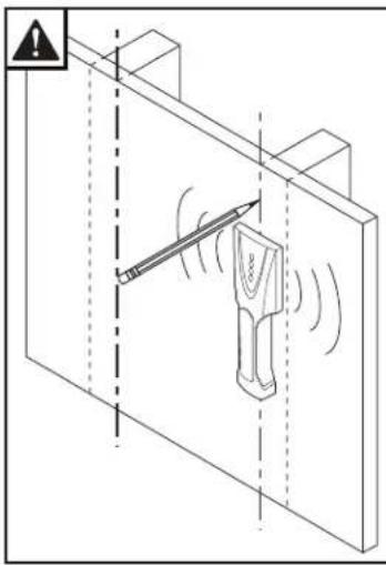
The Mimo Monitor In-Wall Enclosure is designed to fit between studs in the vertical or horizontal direction. The 15.6" In-Wall Box in landscape mode will not fit between two 16" studs unless the studs are notched, see 1-2b below for details. So, it is advised to locate the studs in the area you are planning on installing the enclosure before you cut the drywall so you do not expose a stud by accident. Once you have located the studs on the left and right of where you are going to install the enclosure, cut the necessary hole in the drywall where you want the enclosure installed. Use the chart below to determine the size of the hole needed for the enclosure you are installing.
| Landscape Mode | ||
| Enclosure | Drywall Hole Size to Cut | |
| Width (A) | Height (B) | |
| 7" Tablet Enclosure | 8 3/4" | 5 7/8" |
| 10.1" Tablet Enclosure | 11 3/4" | 8 1/4" |
| 10.1" Vue Display Enclosure | 11 3/4" | 8 1/4" |
| 15.6" Tablet Enclosure | 16 3/4" | 11" |
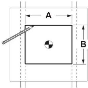
Using dimensions shown, draw outline for in-wall box. Make sure lines are level before removing drywall.
1-2b
When installing the 15.6" Wall Box in landscape mode in a 16" on center stud wall, both studs will have to be notched out .875" (half of the 1.5" stud) by 11" (the height of the box) in order for the box to fit.
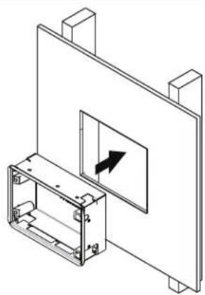
1-3
Insert wall box into hole in drywall with the clips on the inside of the box.
natural_image
Isometric technical diagram of a mechanical assembly with a component and directional arrow (no text or symbols)1-4
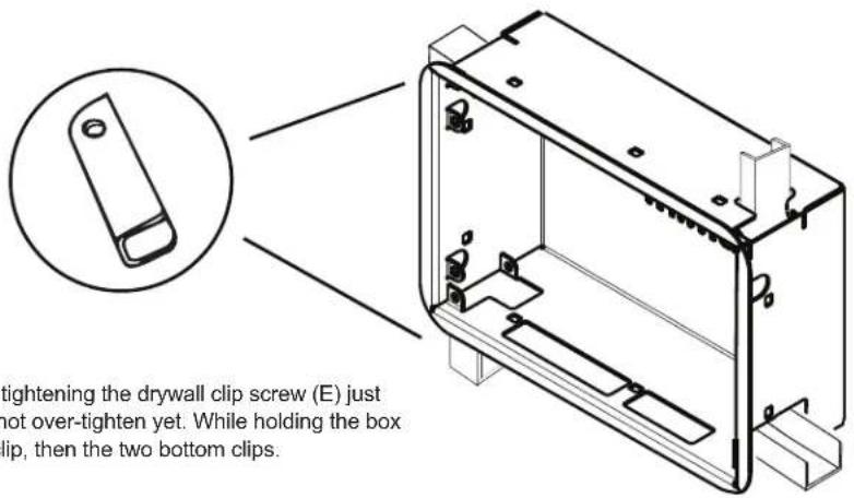
Rotate one of the top drywall clips (D) by tightening the drywall clip screw (E) just enough to secure the box to the wall, do not over-tighten yet. While holding the box in place, repeat this for the opposite top clip, then the two bottom clips.
1-5
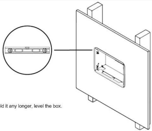
Once box is secure enough that you don't need to hold it any longer, level the box.
1-6
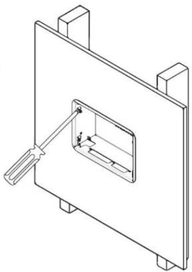
Once the box is level, tighten all four drywall screws (E) so that the enclosure is tightly held in place.
natural_image
Technical line drawing of a mechanical assembly with a tool inserted into a rectangular component (no text or symbols)1-7
Mount the display to the adapter plate (B) using four M4 screws (F) provided and the Vesa 75 holes in the back of the display.
natural_image
Simple line drawing of a screwdriver inside a circle (no text or symbols)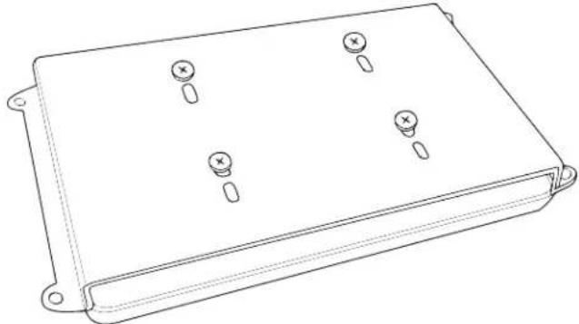
natural_image
Line drawing of a rectangular electronic component with four mounting holes and three screw holes (no text or symbols)1-8
Mount the adapter plate (B) using four M4 screws (F) provided to the wall box.
natural_image
Simple line drawing of a screwdriver inside a circle (no text or symbols)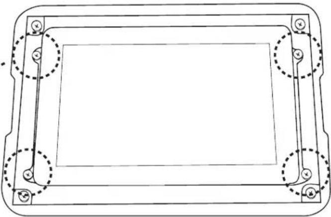
natural_image
Technical line drawing of a rectangular frame with mounting holes and dashed circular cutouts (no text or symbols)1-9
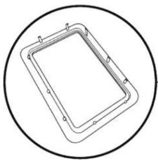
Install the bezel (B) by aligning and pressing in place.
natural_image
Simple line drawing of a rectangular frame enclosed in a circle (no text or symbols)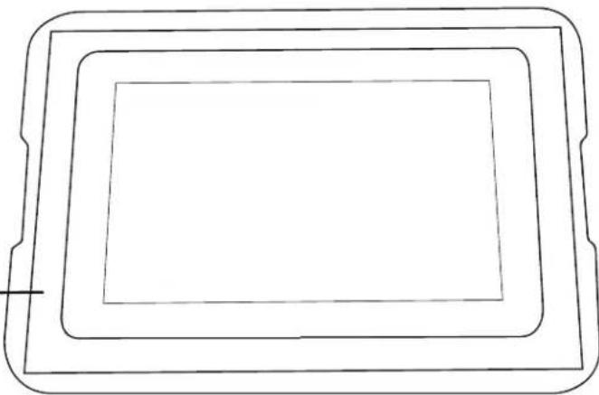
natural_image
Simple line drawing of a rectangular frame with three concentric layers, no text or symbols present.Mimo Monitors
743 Alexander Rd. Suite 15
Princeton, NJ 08540
info@mimomonitors.com
Sales: 1-855-YES-MIMO (937-6466)
2019-0521
Rev 1 - 79047