AW900ITR-Pair - Wi-Fi repeater AvaLAN - Free user manual and instructions
Find the device manual for free AW900ITR-Pair AvaLAN in PDF.

User questions about AW900ITR-Pair AvaLAN
0 question about this device. Answer the ones you know or ask your own.
Ask a new question about this device
Download the instructions for your Wi-Fi repeater in PDF format for free! Find your manual AW900ITR-Pair - AvaLAN and take your electronic device back in hand. On this page are published all the documents necessary for the use of your device. AW900ITR-Pair by AvaLAN.
USER MANUAL AW900ITR-Pair AvaLAN
USER'S MANUAL ADDENDUM Matched Pair Bridges
Certain AvaLAN radios are sold as matched pairs, pre-configured as a wireless Ethernet bridge. The manual supplied with the pair does not include information about the pair configuration, hence this addendum.
This addendum applies to these products:
AW900xTR-PAIR AW2400xTR-PAIR AW5800xTR-PAIR
AW900iTR-PAIR AW2400iTR-PAIR
AW900xTP-PAIR AW2400xTP-PAIR AW5800xTP-PAIR
The pair configuration as shipped from the factory consists of these features:
- One unit of the pair is configured as an Access Point and the other is configured as a Subscriber Unit.
- The Access Point is given the IP Address 192.168.17.17.
- The Subscriber Unit is given the IP Address 192.168.17.18.
- User-specified encryption keys are disabled and the two radios are keyed to each other using the "Auto-Key" method.
- RF Channel selection is set to automatic mode.
If these configuration parameters work for you in your system, you need only to connect antennas, power and LAN and the pair should work transparently, looking just like an Ethernet cable.
If you need to change any of the pair's parameters, you may use the browser interface as described in the accompanying manual. You might need to do this if you need to set the pair to a particular channel, or you wish to provide your own encryption keys. If the default IP Addresses won't work in your system, the best way to change them is by using the ipfinder utility described in the manual and downloadable from www.avalanwireless.com.
In case of difficulty, you may find additional help under the Support tab on our website or by contacting AvaLAN Technical Support using the information in the manual.
Revision 08.11.2010

text_image
Power RF YX RF BX ETH LNX 1 2 3 4 5 6 7 8 9 10 11 12 13 14 15 16 17 18 19 20 21 22 23 24 25 26 27 28 29 30 31 32 33 34 35 36 37 38 39 40 41 42 43 44 45 46 47 48 49 50 51 52 53 54 55 56 57 58 59 60 61 62 63 64 65 66 67 68 69 70 71 72 73 74 75 76 77 78 79 80 81 82 83 84 85 86 87 88 89 90 91 92 93 94 95 96 97 98 99 100 AW900iTR AW900iTR 900 MHz Indoor Wireless Ethernet Radio www.ewlleroindustri.com Subscription Support: (000) 384-0000 AvaLAN WIRELESS 1. 301-102 MTR 1. 1-2 high aggregate data rate 2. 1-3 high aggregate data rate 3. 1-4 high aggregate data rate 4. 1-5 high aggregate data rate 5. 1-6 high aggregate data rate 6. 1-7 high aggregate data rate 7. 1-8 high aggregate data rate 8. 1-9 high aggregate data rate 9. 1-10 high aggregate data rate 10. 1-11 high aggregate data rate 11. 1-12 high aggregate data rate 12. 1-13 high aggregate data rate 13. 1-14 high aggregate data rate 14. 1-15 high aggregate data rate 15. 1-16 high aggregate data rate 16. 1-17 high aggregate data rate 17. 1-18 high aggregate data rate 18. 1-19 high aggregate data rate 19. 1-20 high aggregate data rate 20. 1-21 high aggregate data rate 21. 1-22 high aggregate data rate 22. 1-23 high aggregate data rate 23. 1-24 high aggregate data rate 24. 1-25 high aggregate data rate 25. 1-26 high aggregate data rate 26. 1-27 high aggregate data rate 27. 1-28 high aggregate data rate 28. 1-29 high aggregate data rate 29. 1-30 high aggregate data rate 30. 1-31 high aggregate data rate 31. 1-32 high aggregate data rate 32. 1-33 high aggregate data rate 33. 1-34 high aggregate data rate 34. 1-35 high aggregate data rate 35. 1-36 high aggregate data rate 36. 1-37 high aggregate data rate 37. 1-38 high aggregate data rate 38. 1-39 high aggregate data rate 39. 1-40 high aggregate data rate 40. 1-41 high aggregate data rate 41. 1-42 high aggregate data rate 42. 1-43 high aggregate data rate 43. 1-44 high aggregate data rate 44. 1-45 high aggregate data rate 45. 1-46 high aggregate data rate 46. 1-47 high aggregate data rate 47. 1-48 high aggregate data rate 48. 1-49 high aggregate data rate 49. 1-50 high aggregate data rate 50. 1-51 high aggregate data rate 51. 1-52 high aggregate data rate 52. 1-53 high aggregate data rate 53. 1-54 high aggregate data rate 54. 1-55 high aggregate data rate 55. 1-56 high aggregate data rate 56. 1-57 high aggregate data rate 57. 1-58 high aggregate data rate 58. 1-59 high aggregate data rate 59. 1-60 high aggregate data rate 60. 1-61 high aggregate data rate 61. 1-62 high aggregate data rate 62. 1-63 high aggregate data rate 63. 1-64 high aggregate data rate 64. 1-65 high aggregate data rate 65. 1-66 high aggregate data rate 66. 1-67 high aggregate data rate 67. 1-68 high aggregate data rate 68. 1-69 high aggregate data rate 69. 1-70 high aggregate data rateAW900iTR
USER'S MANUAL
900 MHz Indoor Wireless Ethernet Radio
Thank you for your purchase of the AW900iTR Indoor Wireless Ethernet Radio.
The AW900iTR includes:
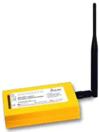
• (1) Radio in indoor yellow plastic case
• (1) AW2-900 Flexible Antenna
• (1) 120 VAC to 6 VDC power adapter
(Ethernet cable not included.)
If you have any questions when configuring your AvaLAN system, the best place to get answers is to visit www.avalanwireless.com.
You will also find the latest updates there.
If more assistance is needed, send email to support@avalanwireless.com.
To speak to a live technician, please call technical support at the number below during normal business hours.
text_image
AW9001TR AW9001TR AW9001TR AW9001TR AW9001TR AW9001TR AW9001TR AW9001TR AW9001TR AW9001TR AW9001TR AW9001TR AW9001TR AW9001TR AW9001TR AW8999 AW8999 AW8999 AW8999 AW8999 AW8999 AW8999 AW8999 AW8999 AW8999 AW8999 AW8999 AW8999 AW8999 AW8999 AW8999 AW8999 AW8877 AW8877 AW8877 AW8877 AW8877 AW8877 AW8877 AW8877 AW8877 AW8877 AW8877 AW8877 AW8877 AW8877 AW8877 AW8877 AW8877 AW8665 AW8665 AW8665 AW8665 AW8665 AW8665 AW8665 AW8665 AW8665 AW8665 AW8665 AW8665 AW8665 AW8665 AW8665 AW8665 AW8665 AW8432 AW8432 AW8432 AW8432 AW8432 AW8432 AW8432 AW8432 AW8432 AW8432 AW8432 AW8432 AW8432 AW8432 AW8432 AW8432 AW8432 AW8331 AW8331 AW8331 AW8331 AW8331 AW8331 AW8331 AW8331 AW8331 AW8331 AW8331 AW8331 AW8331 AW8331 AW8331© 2009 by AvaLAN Wireless Systems Inc. All rights reserved.
Revision 090915.0
125A Castle Drive
Madison, AL 35758
Sales: (866) 533-6216
Technical Support: (650) 384-0000
Customer Service: (650) 641-3011
Fax: (650) 249-3591
Operational summary
The AW900iTR Radio allows the user to create a long-range, wireless Ethernet network with up to 16 subscriber units per access point. The configuration may include any combination of AW900iTR, AW900xTR and AW900xTP radios. (Please note that older AvaLAN 900 MHz radios can exist on the same LAN but cannot be used to form wireless links with the AW900iTR units because link encryption protocols have changed.)
Configuring a wireless link with the AW900iTR requires the establishment elements:
• Each radio must know whether it is to be an access point (AP) or subscriber unit (SU).
• Each radio must have an IP address that is unique among all others on the same network.
• The AP must know how many SUs are expecting communication with it.
- The AP and any given SU must agree on which radio frequency channel they are using. This can be manually set or allowed to change automatically.
- The SU must be assigned a unique subscriber ID to specify which time division slot it will use when communicating with the AP.
• The AP and any given SU must share a common 128-bit encryption key.
The access point (AP) automatically scans for the best of the 12 available radio frequency channels, encrypts Ethernet data received from the network, and transmits it wirelessly to the correct subscriber unit (SU). The AP is constantly monitoring the radio link and can automatically change the channel if performance is degraded due to interference. If two AP units are very close to one another, they may interfere if operating on adjacent frequency channels. Place them at least 10 feet apart or manually select non-adjacent channels for their operation. Also, the SU should be placed at least 10 feet from the AP to avoid overloading the radio's receiver.
Any 10/100 BaseT Ethernet client device (ECD) can be connected to an AW900iTR subscriber unit. Each SU encrypts Ethernet traffic received from the attached ECD and transmits the data wirelessly to its AP. Each SU can be plugged directly into an ECD without adding drivers or loading software. Essentially, once the AP/SU pair is configured and running it behaves like a continuous Ethernet cable.
Physical Setup
- Before placing the radio in its final location, you may want to perform the digital setup procedure described in the next section.
- Connect the AW900iTR's TNC RF connector to a suitable antenna. A simple omni-directional dipole unit (AW2-900) is included and may be used for testing and for relatively undemanding applications. If greater range and/or directionality is required, choose one of our other antenna models. You may see them on our website at www.avalanwireless.com.
- Power is provided to the unit by means of the 120 VAC to 6 VDC wall hanger power supply provided. If it is more convenient, power may be supplied through the Ethernet cable, allowing the power supply to be located at a convenient location away from the radio. A Power Over Ethernet Injector, AW-POE, provides the means for adding DC power to unused wires in the cable. If you wish to use the AW-POE and the Ethernet cable is more than 25 feet long between the POE and the radio, you should use the accessory AW-12VPS wall hanging power supply. It provides 12 volts rather than 6 volts which will compensate for voltage drop in the cable and connectors.
Digital Setup
- Digital configuration is done by means of the AW900iTR's built in browser interface. It should be powered on and connected at least temporarily to a network containing a computer that can run a conventional web browser.
- Download the AvaLAN IP Discovery Utility from our website and extract ipfinder.exe from the zip archive, placing it on your desktop or in a folder.
http://www.avalanwireless.com/ipfinder/ipfinder.zip
Note that this utility only runs on MS Windows, not linux or MAC. If you must use a non-Windows computer for configuration, make sure your subnet mask allows your computer to see 192.168.17.17. Connect to that default IP address with your web browser and continue the setup procedure with step 6.
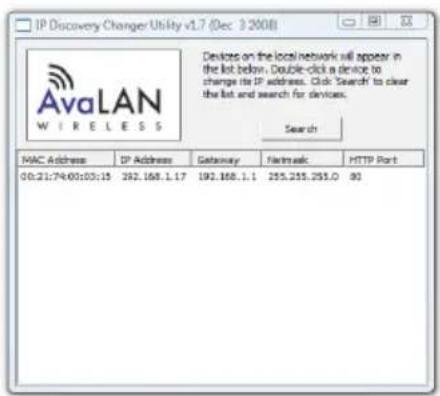
- Run the IP Discovery Utility, ipfinder.exe and you should see a window similar to the view on the next page.
text_image
IP Discovery Changer Utility v1.7 (Dec 3 2008) AvaLAN W I R E L E S S Devices on the local network will appear in the list below. Double-click a device to change its IP address. Click Search to clear the list and search for devices. Search MAC Address IP Address Gateway Bluetooth HTTP Port 00:21:74:00:03:15 392.168.1.17 192.168.1.1 255.255.255.0 80The AW900iTR should appear in the list at the default IP address of 192.168.17.17. If it does not, click “Search” to regenerate the list. If it still does not appear, you have a connection issue and need to re-examine the cabling or you may have a subnet or firewall issue on your computer.
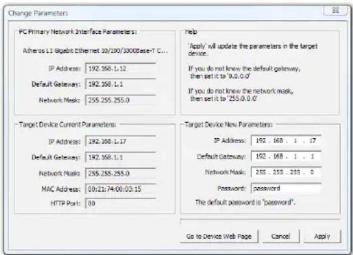
- Double click the list item that refers to the AW900iTR being should see a second window that is similar to this:
text_image
Change Parameters PC Primary Network Interface Parameters: Atheros L1 Gigabit Ethernet 30/100/1000Base-T C... IP Address: 192.168.1.12 Default Gateway: 192.168.1.1 Network Mask: 255.255.255.0 Target Device Current Parameters: IP Address: 192.168.1.17 Default Gateway: 192.168.1.1 Network Mask: 255.255.255.0 MAC Address: 00:21:74:00:03:15 HTTP Port: 89 Help 'Apply' will update the parameters in the target device. If you do not know the default gateway, then set it to '0.0.0.0' If you do not know the network mask, then set it to '255.0.0.0' Target Device New Parameters: IP Address: 192 . 168 . 1 . 17 Default Gateway: 192 . 168 . 1 . 1 Network Mask: 255 . 255 . 255 . 0 Password: password The default password is "password". Go to Device Web Page Cancel ApplyThe information on the left is the current status of the radio, while the boxes on the right allow you to change it. It is important that the IP address of the AW900iTR is in the same subnet as your computer. For example, if the subnet mask is 255.255.255.0 (a class C network), the first three number groups of the IP address must match. Choose your desired parameters and click “Apply.”
- Make note of the chosen IP address and password, then click "Go to Device Web Page." This will cause your default web browser to launch with the device IP address in the browser address bar. Or you may launch the browser on your own and enter the web page address manually: http://[the IP address you just set].
AW900iTR User's Manual
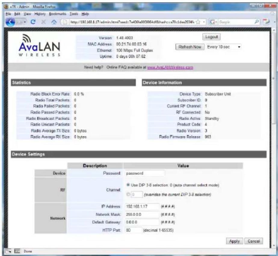
- The browser page that loads first shows the current device information and QoS statistics and provides a login at the upper right. Log in using the password you just specified (or “password” if you kept the default). If the login succeeds, you will see an admin page similar to this:
text_image
eTR - Admin - Mozilla Firefox File Edit View History Bookmarks Tools Help http://192.168.1.17/admin.html?wsed:7406fa00c0064df8hashcc70c1des2034fs Version: 1.48.4003 MAC Address: 00.21.74 00.03.16 Ethernet: 100 Mbps Full Duplex Uptime: 0 days 00h 07:02 Logout Refresh Now Every 10 sec Need help? Online FAQ available at www.AvaLANWireless.com Statistics Device Information Radio Block Error Rate: 0.0 % Radio Total Packets: 0 Radio Failed Packets: 0 Radio Passed Packets: 0 Radio Broadcast Packets: 0 Radio Unicast Packets: 0 Radio Average TX Size: 0 bytes Radio Average RX Size: 0 bytes Device Type: Subscriber Unit Subscriber ID: 0 Current RF Channel: 1 RF Connected: No Radio Active: Standby Product Code: 4 Radio Version: 3 Radio Firmware Release: 063 Device Settings Description Value Device Password password RF Channel Use DIP 3-8 selection: 0 (auto channel select mode) ● 0 (avandias the current DIP 3-8 selection) Network IP Address: 192.168.1.17 (W#A#A) Network Mask: 255.0.0.0 (W#A#A) Default Gateway: 0.0.0.0 (W#A#A) HTTP Port: 80 (decimal 1-65535) Apply Cancel Done- The admin page has sections similar to the login page showing radio statistics and device information plus it adds several new sections. The Device Settings section allows setting the network information and choosing an RF frequency channel. The default is to allow the radio to choose its own frequency based on minimizing interference. If you set a fixed channel, make sure the AP and all SUs use the same one. References to DIPs on this and the next web page refer to switches inside the radio that are used in the legacy method of configuration and may be ignored when using the browser method.
If you scroll down in the Admin browser page, you will come to three more sections:
- A graphical spectrum analyzer display that may help you to select radio channels that avoid interference
- A section to be used if an update to the AW900iTR's firmware is required
- An Advanced Links section with a dire warning about advanced users only.
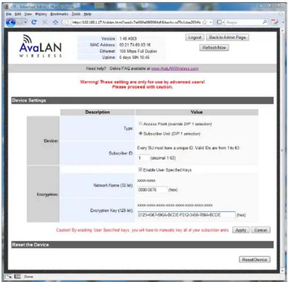
Despite the warning, you will need to click the “Advanced Admin” button in order to set the device type, ID and encryption key. You should then see a page similar to that on the next page.
text_image
AvaLAN WIRELESS Version: 1.48.4003 MAC Address: 00.21.74.00.03.16 Ethernet: 100 Mbps Full Duplex Uptime: 0 days 00h 10:45 Login Back to Admin Page Refresh Now Need help? Online FAQ available at www.AvaLAN/Wireless.com Warning! These setting are only for use by advanced users! Please proceed with caution. Device Settings Description Value Device: Type: Subscriber ID: Every SU must have a unique ID. Valid IDs are from 1 to 63: 1 (decimal 1-63) Encryption: Network Name (32-bit): xxxx-xxxx 0000-0076 (hax) Encryption Key (128-bit): xxxx-xxxx-xxxx-xxxx-xxxx-xxxx-xxxx-xxxx- 0123-4567-890A-BCDE-F012-3456-789A-BCDE (hax) Enable User Specified Keys Caution! By enabling User Specified keys, you will have to manually key all of your subscriber units Apply Cancel Reset the Device ResetDevice Done-
On the Advanced Admin page, set the parameters as follows:
-
Choose Device Type: Access Point or Subscriber Unit.
• For Subscriber Units, assign unique ID numbers in numeric order from 1 to 63. - For an Access Point, enter the number of Subscriber Units that will be communicating with it.
- Click the box labeled "Enable User Specified Keys."
- Choose an 8-digit hex (0-9 and A-F) Network Name that will be common among the AP and its SUs and enter it. The hyphen is required.
- Choose a 32-digit hex encryption key and enter it. Again, the hyphens are required. This key must match between the AP and the SU so make a note of it as well.
After entering the parameters, click the "Apply" button to save them to the radio.
- When all of the radios are keyed and operating, connect them to your network and Ethernet devices as desired and cycle the radio's power to begin normal operation. Now, browser management of the SUs can be performed over the wireless network. Note: avoid plugging actively linked radios into the same switch because this will corrupt its routing table and may cause network problems just as if you had plugged a CAT5 cable directly between two ports of a switch.
900 MHz Channels
| Channel Center Frequency |
| 0 Auto Mode |
| 1 903.12500 MHz |
| 2 905.20833 MHz |
| 3 907.29167 MHz |
| 4 909.37500 MHz |
| 5 911.45833 MHz |
| 6 913.54167 MHz |
| 7 915.62500 MHz |
| 8 917.70833 MHz |
| 9 919.79167 MHz |
| 10 921.87500 MHz |
| 11 923.95833 MHz |
| 12 926.04167 MHz |
Limited Warranty
This product is warranted to the original purchaser for normal use for a period of 360 days from the date of purchase. If a defect covered under this warranty occurs, AvaLAN will repair or replace the defective part, at its option, at no cost. This warranty does not cover defects resulting from misuse or modification of the product.
Compliance Statement ( Part 15.19 )
This device complies with Part 15 of the FCC Rules.
Operation is subject to the following two conditions:
- This device may not cause harmful interference, and
- This device must accept any interference received, including interference that may cause undesired operation.
Warning ( Part 15.21 )
Changes or modifications not expressly approved by the party responsible for compliance could void the user's authority to operate the equipment.
RF Exposure (OET Bulletin 65)
To comply with FCC RF exposure requirements for mobile transmitting devices, this transmitter should only be used or installed at locations where there is at least 20cm separation distance between the antenna and all persons.
Information to the User - Part 15.105 (b)
This equipment has been tested and found to comply with the limits for a Class B digital device, pursuant to part 15 of the FCC Rules. These limits are designed to provide reasonable protection against harmful interference in a residential installation. This equipment generates, uses and can radiate radio frequency energy and, if not installed and used in accordance with the instructions, may cause harmful interference to radio communications. However, there is no guarantee that interference will not occur in a particular installation. If this equipment does cause harmful interference to radio or television reception, which can be determined by turning the equipment off and on, the user is encouraged to try to correct the interference by one or more of the following measures:
--Reorient or relocate the receiving antenna.
--Increase the separation between the equipment and receiver.
--Connect the equipment into an outlet on a circuit different from that to which the receiver is connected.
--Consult the dealer or an experienced radio/TV technician for help.