JACP12-030696 - Air Conditioning Jocel - Free user manual and instructions
Find the device manual for free JACP12-030696 Jocel in PDF.

| Brand | Jocel |
| Model | JACP12-030696 |
| Product Type | Portable Air Conditioner |
| Cooling Capacity | 12000 BTU (approx) |
| Energy Efficiency | EER 10.0 (typical) |
| Power Supply | 115V ~ 60Hz |
| Power Consumption | 1200W (cooling) |
| Refrigerant | R-410A |
| Airflow | 250 CFM |
| Noise Level | 52 dB (low), 56 dB (high) |
| Dimensions (WxHxD) | 17.5 x 28.5 x 15.0 inches |
| Weight | 62 lbs |
| Functions | Cool, Fan, Dehumidify |
| Remote Control | Yes, included |
| Timer | 24-hour on/off timer |
| Filter Type | Washable mesh filter |
| Filter Cleaning | Every 2 weeks |
| Drainage | Self-evaporating (auto) or continuous |
| Installation | Window kit included |
| Warranty | 1 year limited |
Frequently Asked Questions - JACP12-030696 Jocel
User questions about JACP12-030696 Jocel
0 question about this device. Answer the ones you know or ask your own.
Ask a new question about this device
Download the instructions for your Air Conditioning in PDF format for free! Find your manual JACP12-030696 - Jocel and take your electronic device back in hand. On this page are published all the documents necessary for the use of your device. JACP12-030696 by Jocel.
USER MANUAL JACP12-030696 Jocel
natural_image
White portable air purifier with control panel and wheels (no visible text or symbols)MANUAL DE INSTRUÇÕES MANUAL DE INSTRUCCIONES INSTRUCTION MANUAL
ÍNDICE

natural_image
Simple line drawing of an open book with no text or symbols visibleNotas:
ACESSÓRIOS
natural_image
White JOCEL remote control with 12 function buttons (no readable text beyond branding)
LIGAR – Interruptor Liga/Desliga

MODO – Seletor de MODO
natural_image
Line drawing of a window unit connected to a portable air conditioner unit (no text or symbols)Fig.5
natural_image
Line drawing of a wall-mounted air conditioner unit connected to a cabinet (no text or symbols)Fig. 5a
natural_image
Line drawing of an air conditioner unit with ductwork and control panel (no text or symbols)natural_image
Line drawing of a portable air conditioner unit mounted on a wall, with 30cm height dimension标注 (no text or symbols on the device itself)Fig. 8
natural_image
Simple line drawing of a container with two downward arrows and a small circular button at the bottom (no text or symbols)Tamanho da janela min:67.5cm(2.21ft) max:123cm(4.04ft)
natural_image
Line drawing of a wall-mounted air conditioner unit connected to a cabinet (no text or symbols)Fig. 9
MANUTENÇÃO
Declaração:
natural_image
Pure electrical circuit lines without any symbols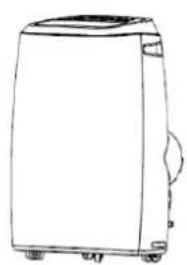
natural_image
Line drawing of a portable washing machine (no text or symbols)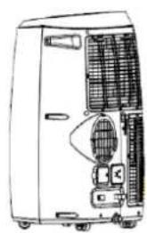
natural_image
Line drawing of a portable industrial machine with ventilation ducts and control panel (no text or symbols)1 Fig.10

Notas:
natural_image
White JOCEL remote control with multiple function buttons (no readable text beyond brand logo)

ENCENDER – Interruptor Encender/Apagar
MODO – Selector de MODO
natural_image
Line drawing of a window unit connected to a portable air conditioner unit (no text or symbols)Fig.5

natural_image
Line drawing of a simple air conditioner unit attached to a cabinet (no text or symbols)Fig. 5a
natural_image
Line drawing of an industrial air conditioner unit with ductwork and ventilation duct (no text or symbols)natural_image
Line drawing of a simple air conditioner unit mounted on a wall-mounted unit, with dimension labels (30CM) shown at both ends (no text or symbols on the device itself)Fig.7
natural_image
Simple line drawing of a container with two downward arrows and a small circular element at the bottom (no text or symbols)Tamaño de la ventana min:67.5cm(2.21ft) max:123cm(4.04ft)
natural_image
Line drawing of a wall-mounted air conditioner unit connected to a panel (no text or symbols)Fig. 9
MANTENIMIENTO
Declaración:
natural_image
Pure electrical circuit lines without any symbols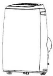
natural_image
Line drawing of a rectangular electronic device with a lid and wheels (no text or symbols)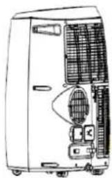
natural_image
Line drawing of a portable air conditioner unit with cooling fans and ventilation slots (no text or symbols)Fig.10
1. Filtro de aire
Safety Awareness....40
Name of Parts....45
Accessories....45
Appearance and Function of Control Panel....46
Appearance and Function of Remote Controller....47
Operation Introduction 48
Installation 51
Maintenance 52
Troubleshooting....53
General Warranty Terms 54
Declaration of conformity 55
VERY IMPORTANT!
Please do not install or use your mobile air conditioner before you have carefully read this manual. Please keep this instruction manual for an eventual product warranty and for future reference.
WARNING
- Do not use means to accelerate the defrosting process or to clean, other than those recommended by the manufacturer.
- The appliance shall be stored in a room without continuously operating ignition sources (for example: open flames, an operating gas appliance or an operating electric heater).
- Do not pierce or burn.
- Be aware that refrigerants may not contain an odour.
- Appliance shall be installed, operated and stored in a room with a floor area larger than X m2.
(X=4 for 5000Btu/h,7000Btu/h,8000Btu/h; X=7.7 for 9000Btu/h,10000Btu/h,10500Btu/h; X=10.1 for 12000Btu/h)
WARNING
Specific information regarding appliances with R 290 refrigerant gas.
• Thoroughly read all of the warnings.
- When defrosting and cleaning the appliance, do not use any tools other than those recommended by the manufacturing company.
- The appliance must be placed in an area without any continuously sources of ignition (for example: open flames, gas or electrical appliances in operation).
- Do not puncture and do not burn.
- Appliance shall be installed, operated and stored in a room with a floor area larger than X m2.
(X=4 for 5000Btu/h,7000Btu/h,8000Btu/h; X=7.7 for 9000Btu/h,10000Btu/h,10500Btu/h; X=10.1 for 12000Btu/h).
- This appliance contains Y g (see rating label back of unit) of R290 refrigerant gas.
- R290 is a refrigerant gas that complies with the European directives on the environment. Do not puncture any part of the refrigerant circuit.
- If the appliance is installed, operated or stored in a nonventilated area, the room must be designed to prevent to the accumulation of refrigerant leaks resulting in a risk of fire or explosion due to ignition of the refrigerant caused by electric heaters, stoves, or other sources of ignition.
- The appliance must be stored in such a way as to prevent mechanical failure.
- Individuals who operate or work on the refrigerant circuit must have the appropriate certification issued by an accredited organization that ensures competence in handling refrigerants according to a specific evaluation recognized by associations in the industry.
- Repairs must be performed based on the recommendation from the manufacturing company. Maintenance and repairs that require the assistance of other qualified personnel must be performed under the supervision of an individual specified in the use of flammable refrigerants.
- Do not use the unit on a socket under repairs or not installed properly.
- Do not use the unit, follow these precautions:
A: Near to source of fire.
B: An area where oil is likely to splash.
C: An area exposed to direct sunlight.
D: An area where water is likely to splash.
E: Near a bath, a shower or a swimming pool.
-
Never insert your fingers, rods into the air outlet. Take special care to warn children of these dangers.
-
Keep the unit upward while transport and storage, for the compressor locates properly.
-
Before cleaning the air-conditioner, always turn off or disconnect the power supply.
-
When moving the air-conditioner, always turn off and disconnect the power supply, and move it slowly.
-
To avoid the possibility of fire disaster, the air-conditioner shall not be covered.
-
All the air-conditioner sockets must comply with the local electric safety requirements. If necessary, please check it for the requirements.
-
Young children should be supervised to ensure that they do not play with the appliance.
-
If the supply cord is damaged, it must be replaced by the manufacturer, its service agent or similarly qualified persons in order to avoid a hazard.
-
This appliance can be used by children aged from 8 years and above and persons with reduced physical, sensory or mental capabilities or lack of experience and knowledge if they have been given supervision or instruction concerning use of the appliance in a safe way and understand the hazards involved. Children shall not play with the appliance. Cleaning and user maintenance shall not be made by children without supervision.
-
The appliance shall be installed in accordance with national wiring regulations.
13.Details of type and rating of fuses : φ5*15.5mm 2W 10Ω
- Recycling
This marking indicates that this product should not be disposed with other household wastes throughout the EU. To prevent possible harm to the environment or human health from uncontrolled waste disposal, recycle it responsibly to promote the sustainable reuse of material resources. To return your used device, please use the return and collection systems or contact the retailer where the product was purchased. They can take this product for environmental safe recycling.
- GWP: R290: 3
- Contact authorized service technician for repair or maintenance of this unit.
- Do not pull, deform. or modify the power supply cord, or immerse it in water. Pulling or misuse of the power supply cord can result in damage to the unit and cause electrical shock.
- Compliance with national gas regulations shall be observed.
- Keep ventilation openings clear of obstruction.
- Any person who is involved with working on or breaking into a refrigerant circuit should hold a current valid
certificate from an industry-accredited assessment authority, which authorizes their competence to handle refrigerants safely in accordance with an industry recognized assessment specification.
- Servicing shall only be performed as recommended by the equipment manufacturer. Maintenance and repair requiring the assistance of other skilled personnel shall be carried out under the supervision of the person competent in the use of flammable refrigerants.
- Do not operate or stop the unit by inserting or pulling out Die power plug, it may cause electric shock or fire due to heat generation.
- Unplug the unit if strange sounds, smell, or smoke comes from it.
natural_image
Two symbolic icons: a triangular warning triangle with a flame symbol and an open book, both without any text or labels.Notes:
-If any parts damage, please contact the dealer or a designated repair shop;
-In case of any damage, please turn off the air switch, disconnect the power supply, and contact the dealer or a designated repair shop;
-In any case, the power cord shall be firmly grounded.
-To avoid the possibility of danger, if power cord is damaged, please turn off the air switch and disconnect the power supply. It must be replaced from the dealer or a designated repair shop.
INSTRUCTIONS FOR REPAIRING APPLIANCES CONTAINING R290
1 GENERAL INSTRUCTIONS
1.1 Checks to the area
Prior to beginning work on systems containing flammable refrigerants, safety checks are necessary to ensure that the risk of ignition is minimised. For repair to the refrigerating system, the following precautions shall be complied with prior to conducting work on the system.
1.2 Work procedure
Work shall be undertaken under a controlled procedure so as to minimise the risk of a flammable gas or vapour being present while the work is being performed.
1.3 General work area
All maintenance staff and others working in the local area shall be instructed on the nature of work being carried out. Work in confined spaces shall be avoided. The area around the workspace shall be sectioned off. Ensure that the conditions within the area have been made safe by control of flammable material.
1.4 Checking for presence of refrigerant
The area shall be checked with an appropriate refrigerant detector prior to and during work, to ensure the technician is aware of potentially flammable atmospheres. Ensure that the leak tection equipment being used is suitable for use with flammable refrigerants, i.e. nonsparking, adequately sealed or intrinsically safe.
1.5 Presence of fire extinguisher
If any hot work is to be conducted on the refrigeration equipment or any associated parts, propriate fire extinguishing equipment shall be available to hand. Have a dry powder or CO 2 fire extinguisher adjacent to the charging area.
1.6 No ignition sources
No person carrying out work in relation to a refrigeration system which involves exposing any pipe work that contains or has contained flammable refrigerant shall use any sources of ignition in such a manner that it may lead to the risk of fire or explosion. All possible ignition sources, including igarette smoking, should be kept sufficiently far away from the site of installation, repairing, removing and disposal, during which flammable refrigerant can possibly be released to the surrounding space. Prior to work taking place, the area around the equipment is to be surveyed to make sure that there are no flammable hazards or ignition risks. "No Smoking" signs shall be displayed.
1.7 Ventilated area
Ensure that the area is in the open or that it is adequately ventilated before breaking into the system or conducting any hot work. A degree of ventilation shall continue during the period that the work is carried out. The ventilation should safely disperse any released refrigerant and preferably expel it externally into the atmosphere.
1.8 Checks to the refrigeration equipment
Where electrical components are being changed, they shall be fit for the purpose and to the correct specification. At all times the manufacturer's maintenance and service guidelines shall be followed. If in doubt consult the manufacturer's technical department for assistance. The following checks shall be applied to installations using flammable refrigerants: the charge size is in accordance with the room size within which the refrigerant containing parts are installed; the ventilation machinery and outlets are operating adequately and are not obstructed; if an indirect refrigerating circuit is being used, the secondary circuit shall be checked for the presence of refrigerant; marking to the equipment continues to be visible and legible. Markings and signs that are illegible shall be corrected; refrigeration pipe or components are installed in a position where they are unlikely to be exposed to any substance which may corrode refrigerant containing compo
nents, unless the components are constructed of materials which are inherently resistant to being corroded or are suitably protected against being so corroded.
1.9 Checks to electrical devices
Repair and maintenance to electrical components shall include initial safety checks and component inspection procedures. If a fault exists that could compromise safety, then no electrical supply shall be connected to the circuit until it is satisfactorily dealt with. If the fault cannot be corrected immediately but it is necessary to continue operation, an adequate temporary solution shall be used. This shall be reported to the owner of the equipment so all parties are advised.
Initial safety checks shall include: that capacitors are discharged: this shall be done in a safe manner to avoid possibility of sparking; that there no live electrical components and wiring are exposed while charging, recovering or purging the system; that there is continuity of earth bonding.
2 REPAIRS TO SEALED COMPONENTS
2.1 During repairs to sealed components, all electrical supplies shall be disconnected from the equipment being worked upon prior to any removal of sealed covers, etc. If it is absolutely necessary to have an electrical supply to equipment during servicing, then a permanently operating form of leak detection shall be located at the most critical point to warn of a potentially hazardous situation.
2.2 Particular attention shall be paid to the following to ensure that by working on electrical components, the casing is not altered in such a way that the level of protection is affected.
This shall include damage to cables, excessive number of connections, terminals not made to original specification, damage to seals, incorrect fitting of glands, etc. Ensure that apparatus is mounted securely. Ensure that seals or sealing materials have not degraded such that they no longer serve the purpose of preventing the ingress of flammable atmospheres. Replacement parts shall be in accordance with the manufacturer's specifications.
NOTE The use of silicon sealant may inhibit the effectiveness of some types of leak detection equipment. Intrinsically safe components do not have to be isolated prior to working on them.
3 REPAIR TO INTRINSICALLY SAFE COMPONENTS
Do not apply any permanent inductive or capacitance loads to the circuit without ensuring that this will not exceed the permissible voltage and current permitted for the equipment in use.
Intrinsically safe components are the only types that can be worked on while live in the presence of a flammable atmosphere. The test apparatus shall be at the correct rating. Replace components only with parts specified by the manufacturer. Other parts may result in the ignition of refrigerant in the atmosphere from a leak.
4 CABLING
Check that cabling will not be subject to wear, corrosion, excessive pressure, vibration, sharp edges or any other adverse environmental effects. The check shall also take into account the effects of aging or continual vibration from sources such as compressors or fans.
5 DETECTION OF FLAMMABLE REFRIGERANTS
Under no circumstances shall potential sources of ignition be used in the searching for or detection of refrigerant leaks. A halide torch (or any other detector using a naked flame) shall not be used.
6 LEAK DETECTION METHODS
The following leak detection methods are deemed acceptable for systems containing flammable refrigerants. Electronic leak detectors shall be used to detect flammable refrigerants, but the sensitivity may not be adequate, or may need recalibration. (Detection equipment shall be calibrated in a refrigerant-free area.) Ensure that the detector is not a potential source of ignition and is suitable for the refrigerant used. Leak detection equipment shall be set at a percentage of the LFL of the refrigerant and shall be calibrated to the refrigerant employed and the appropriate percentage of gas (25% maximum) is confirmed. Leak detection fluids are suitable for use with most refrigerants but the use of detergents containing chlorine shall be avoided as the chlorine may react with the refrigerant and corrode the copper pipe-work. If a leak is suspected, all naked flames shall be removed/extinguished. If a leakage of refrigerant is found which requires brazing, all of the refrigerant shall be recovered from the system, or isolated (by means of shut off valves) in a part of the system remote from the leak. Oxygen free nitrogen (OFN) shall then be purged through the system both before and during the brazing process.
7 REMOVAL AND EVACUATION
When breaking into the refrigerant circuit to make repairs – or for any other purpose – conventional procedures shall be used. However, it is important that best practice is followed since flammability is a consideration. The following procedure shall be adhered to: remove refrigerant; purge the circuit with inert gas; evacuate; purge again with inert gas; open the circuit by cutting or brazing. The refrigerant charge shall be recovered into the correct recovery cylinders. The system shall be “flushed” with OFN to render the unit safe. This process may need to be repeated several times. Compressed air or oxygen shall not be used for this task. Flushing shall be achieved by breaking the vacuum in the system with OFN and continuing to fill until the working pressure is achieved, then venting to atmosphere, and finally pulling down to a vacuum. This process shall be repeated until no refrigerant is within the system. When the final OFN charge is used, the system shall be vented down to atmospheric pressure to enable work to take place. This operation is absolutely vital if brazing operations on the pipework are to take place.
Ensure that the outlet for the vacuum pump is not close to any ignition sources and there is ventilation available.
8 CHARGING PROCEDURES
In addition to conventional charging procedures, the following requirements shall be followed.
- Ensure that contamination of different refrigerants does not occur when using charging equipment. Hoses or lines shall be as short as possible to minimise the amount of refrigerant contained in them.
- Cylinders shall be kept upright.
- Ensure that the refrigeration system is earthed prior to charging the system with refrigerant.
- Label the system when charging is complete (if not already).
- Extreme care shall be taken not to overfill the refrigeration system.
Prior to recharging the system, it shall be pressure tested with OFN. The system shall be leak tested on completion of charging but prior to commissioning. A follow up leak test shall be carried out prior to leaving the site.
9 DECOMMISSIONING
Before carrying out this procedure, it is essential that the technician is completely familiar
with the equipment and all its detail. It is recommended good practice that all refrigerants are recovered safely. Prior to the task being carried out, an oil and refrigerant sample shall be taken in case analysis is required prior to re-use of reclaimed refrigerant. It is essential that electrical power is available before the task is commenced.
a) Become familiar with the equipment and its operation.
b) Isolate system electrically.
c) Before attempting the procedure ensure that: mechanical handling equipment is available, if required, for handling refrigerant cylinders; all personal protective equipment is available and being used correctly; the recovery process is supervised at all times by a competent person; recovery equipment and cylinders conform to the appropriate standards.
d) Pump down refrigerant system, if possible.
e) If a vacuum is not possible, make a manifold so that refrigerant can be removed from various parts of the system.
f) Make sure that cylinder is situated on the scales before recovery takes place.
g) Start the recovery machine and operate in accordance with manufacturer's instructions.
h) Do not overfill cylinders. (No more than 80 % volume liquid charge).
i) Do not exceed the maximum working pressure of the cylinder, even temporarily.
j) When the cylinders have been filled correctly and the process completed, make sure that the cylinders and the equipment are removed from site promptly and all isolation valves on the equipment are closed off.
k) Recovered refrigerant shall not be charged into another refrigeration system unless it has been cleaned and checked.
10 LABELLING
Equipment shall be labelled stating that it has been de-commissioned and emptied of refri- gerant. The label shall be dated and signed.
Ensure that there are labels on the equipment stating the equipment contains flammable refrigerant.
11 RECOVERY
When removing refrigerant from a system, either for servicing or decommissioning, it is recommended good practice that all refrigerants are removed safely. When transferring refrigerant into cylinders, ensure that only appropriate refrigerant recovery cylinders are employed. Ensure that the correct number of cylinders for holding the total system charge are available. All cylinders to be used are designated for the recovered refrigerant and labelled for that refrigerant (i.e. special cylinders for the recovery of refrigerant). Cylinders shall be complete with pressure relief valve and associated shut-off valves in good working order. Empty recovery cylinders are evacuated and, if possible, cooled before recovery occurs.
The recovery equipment shall be in good working order with a set of instructions concerning the equipment
that is at hand and shall be suitable for the recovery of flammable refrigerants. In addition, a set of calibrated weighing scales shall be available and in good working order. Hoses shall be complete with leak-free disconnect couplings and in good condition. Before using the recovery machine, check that it is in satisfactory working order, has been properly maintained and that any associated electrical components are sealed to prevent ignition in the event of a refrigerant release. Consult manufacturer if in doubt.
The recovered refrigerant shall be returned to the refrigerant supplier in the correct recovery cylinder, and the relevant Waste Transfer Note arranged. Do not mix refrigerants in recovery units and especially not in cylinders.
If compressors or compressor oils are to be removed, ensure that they have been evacuated to an acceptable level to make certain that flammable refrigerant does not remain within the lubricant. The evacuation process shall be carried out prior to returning the compressor to the suppliers. Only electric heating to the compressor body shall be employed to accelerate this process. When oil is drained from a system, it shall be carried out safely.
NAME OF PARTS
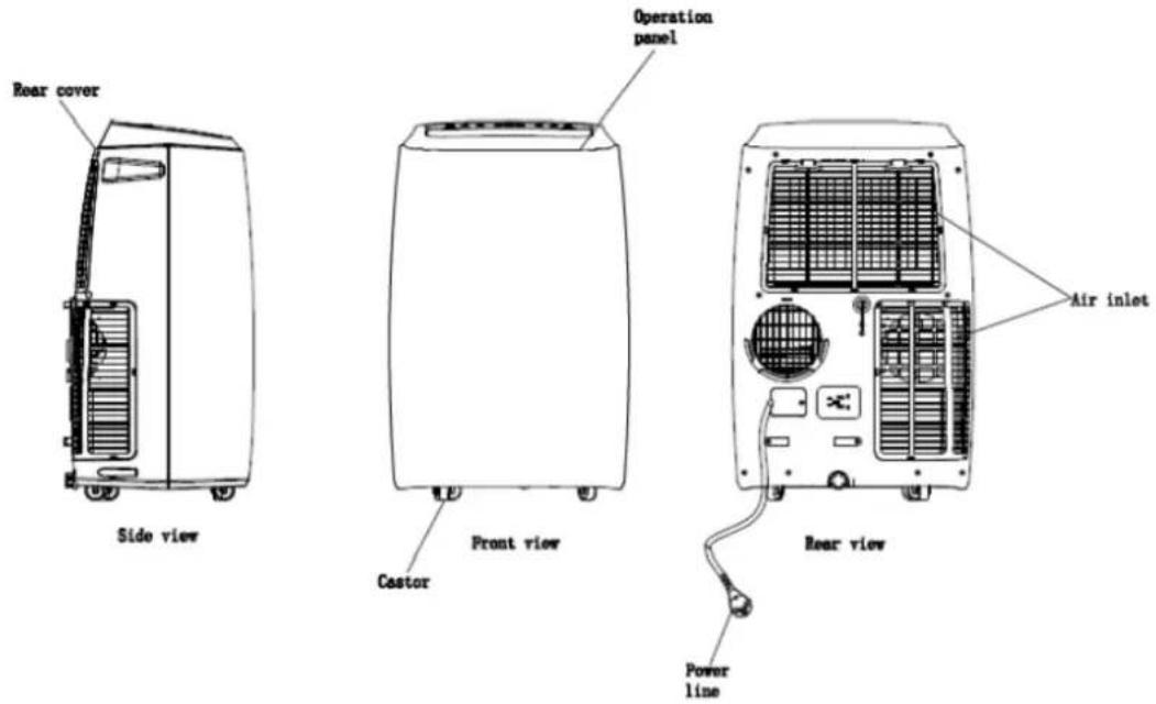
Fig. 1
ACCESSORIES
| Part | Description | Quantity | Size |
 | Main Air Conditioner Unit | 1 | 440*335*715mm |
 | Hot-Air exhaust hose | 1 | Length:1500mmDiametre:150mm |
 | Hose Connector (Window end) | 1 | Diametre:150mm |
| [ccw2] | Hose Connector (Air Conditioner end) | 1 | Diametre:150mm |
 | Window Kit | 1 | Length:500mm |
 | Remte Control | 1 | 100*45mm |
Fig.2
After unpacking, please check whether the above-mentioned accessories are included, and check their purposes in the installation introduction in this manual.
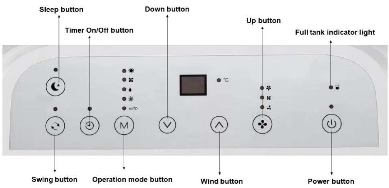
APPEARANCE AND FUNCTION OF CONTROL PANEL
natural_image
White JOCEL remote control with multiple function buttons (no readable text beyond brand logo)

POWER – On/Off switch
MODE - MODE selector
TIMER – Hourly programming
SPEED – Fan speed selector
TEMP+ - Temperature selector up
TEMP- - Temperature selector down
SLEEP – Night operation selector
SWING – Auto air flow selector
Before starting operations in this section:
3) Find a place where there is power supply nearby.
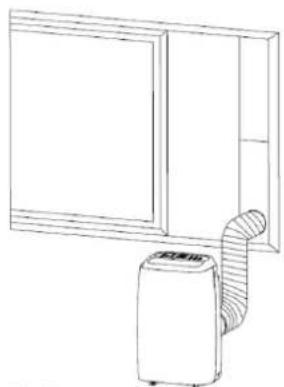
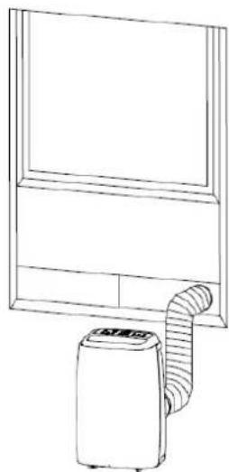
4) As shown in Fig.5 and Fig.5a, install the exhaust hose, and adjust the window position well.
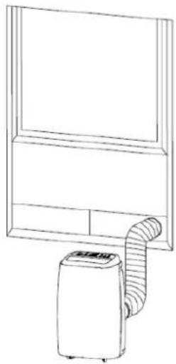
natural_image
Line drawing of a portable air conditioner unit connected to a wall-mounted unit (no text or symbols)Fig.5
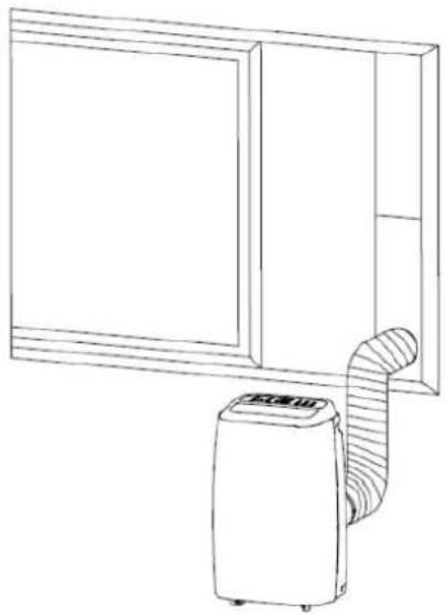
natural_image
Line drawing of a simple air conditioner unit next to a cabinet (no text or symbols)Fig.5a
5) Insert the power cord into an grounded AC220-240V/50Hz socket;
6) As shown in Fig. 6, connect drain hose well (only for using heating model).
7) Press the POWER button to turn on the air-conditioner.
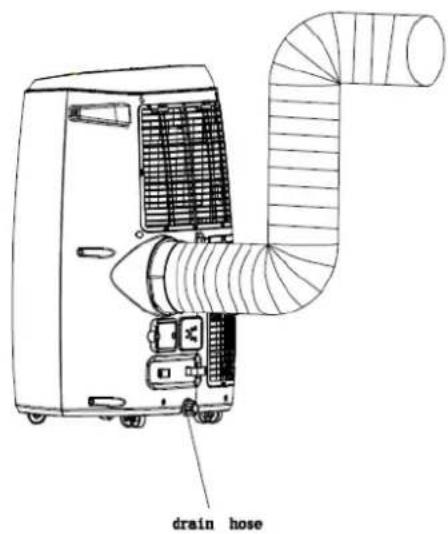
Fig.6
1. Before Using
Notice:
Operation temperature range:
| Maximum cooling | Minimum cooling | |
| DB/WB(°C) | 35/24 | 18/12 |
| Maximum heating | Minimum heating | |
| DB/WB(°C) | 27/--- | 7/--- |
Check up whether the exhaust hose has been mounted properly.
Cautions for cooling and dehumidifying operations:
-When using functions on cooling and dehumidifying, keep an interval of at least 3 minutes between each ON/OFF.
-Power supply meets the requirements.
-The socket is for AC use.
-Do not share one socket with other appliances.
-Power supply is AC220--240V, 50Hz
2. Auto Mode
According to the current room temperature, automatically select the mode: cooling, dehumidifying or fan (see table 1).
Table 1
| Room Temperature (Tr) | Tr<23 °C | 23°C≤Tr <26°C | Tr ≥26°C |
| Mode | Heating | Dehumidify | Cooling |
| Set Temperature | 21°C | 23°C | 25°C |
3. Cooling operation
-Press the "Mode" button till the "Cool" icon appears.
-Press the "DOWN" or "UP" button to select a desired room temperature. (16°C-31°C)
-Press the "WIND" button to select wind speed.
4. Dehumidifying operation
-Press the "Mode" button till the "Dehumidify" icon appears.
-Automatically set the selected temperature to current room temperature minus 2°C.
-Automatically set the fan motor to LOW wind speed.
5. Fan operation
-Press the "Mode" button till the "Fan" icon appears.
-Press the "WIND" button to select wind speed.
6. Heating operation (this function is not available for a cold-single unit)
-Press the "Mode" button till the "Heat" icon appears.
-Press the "DOWN" or "UP" button to select a desired room temperature. (16°C-31°C)
-Press the "WIND" button to select wind speed.
7. Timer operation
Timer ON setting:
-When the air-conditioner is OFF, press the "Timer" button and select a desired-ON time through the temperature and time setting buttons.
- "Preset ON Time" is displayed on the operation panel.
-ON time can be regulated at any time in 0-24 hours.
Timer OFF setting
-When the air-conditioner ON, press "Timer" button and select a desired OFF time through the temperature and time setting buttons.
- "Preset OFF Time" is displayed on the operation panel.
-OFF time can be regulated at any time in 0-24 hours.
8. Swing (Air Flow)
After machine turns on, press this key, the louver will swing continuously up and down; when press this button again the movement will stop and the louver remain in that position.
9. Sleep Control Function
-While in cooling mode, press the SLEEP key to set the temperature. It increases 1 °C after an hour and at most increases 2 °C after 2 hours.
-While in heating mode, press the SLEEP key to set the temperature. It decreases 1 °C after an hour and at most decreases 2 °C after 2 hours.
-Press the SLEEP key again can cancel the setting.
10. Drainage
Internal tank water full alarm function. The inner water tank in the air-conditioner has one water level safety switches, it controls water level. When water level reaches an anticipated height, the water full indicator lamp lights up. (If water pump is damaged, when the water is full, please remove the rubber blockage at the bottom of unit, and all water will drain outside.)
1. Installation Explanations:
-A removal air-conditioner shall be installed in the flat and empty place all around. Don't block the air outlet, and the required distance around should be at least 30cm. (See Fig.7)
-Should not be installed in dry cleaner.
-Socket wiring should be in accordance with the local electric safety requirements.
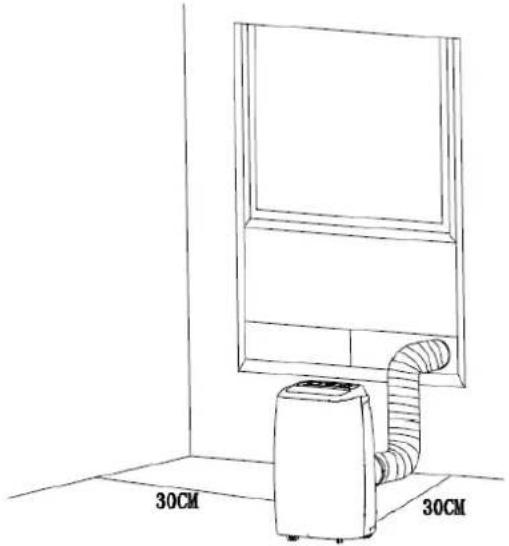
natural_image
Line drawing of a simple air conditioner unit mounted on a wall-mounted unit, with dimension labels (30CM) shown at both ends (no text or symbols on the device itself)Fig.7
4. Introduction to Exhaust Hose Installation
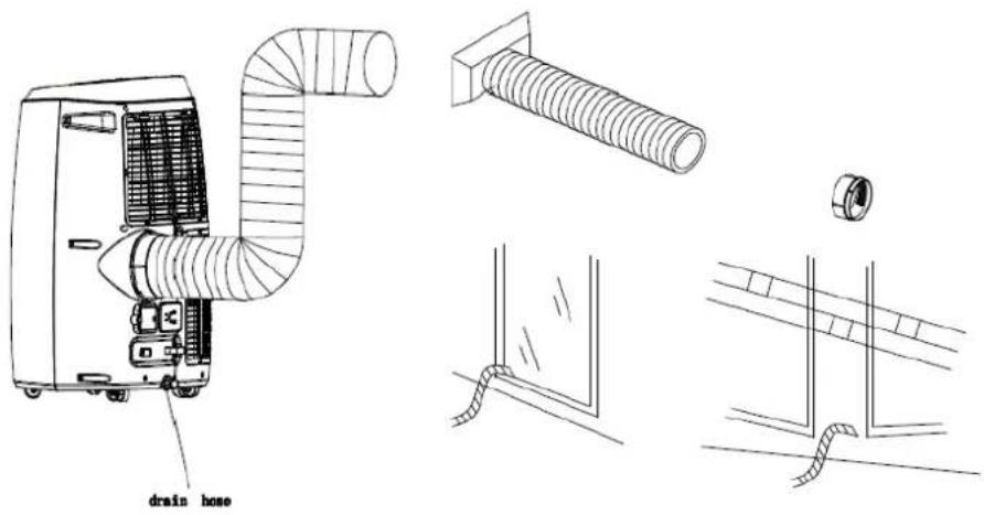
Fig.8
5. Temporary installation
- Twist both ends of the exhaust hose into the square fixing clip and the flat fixing clip.
- Insert the square fixing clip into openings at back of the air conditioner (see Fig.8).
- Put the other end of the exhaust hose to the near windowsill.
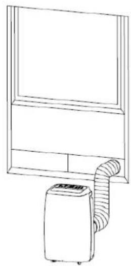
6. Window Slider Kit Installation
The installation manner of window slider kit is mostly in "horizontal" and "vertical", No much difference in actual process. As shown Fig.9, check the min. and max. size of the window.
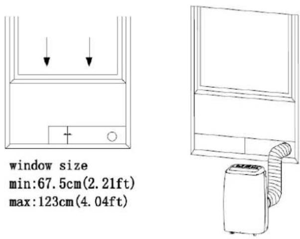
window size
min:67.5cm(2.21ft)
max:123cm(4.04ft)
Fig.9
MAINTENANCE
Declaration:
1) Before cleaning, be sure to disconnect the unit from any electric supply outlet;
2) Do not use gasoline or other chemicals to clean the unit;
3) Do not wash the unit directly;
4) If the conditioner is damaged, please contact the dealer or repair shop.
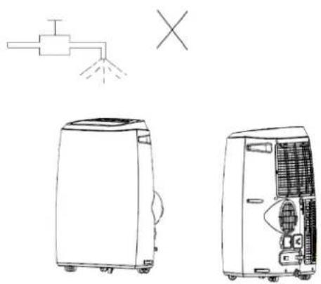
Fig.10
1. Air Filter
1 If the air filter becomes clogged with dust/dirt, the air filter should be cleaned once every two weeks.
2 Dismounting
Open the air inlet grille and take off air filter.
3 Cleaning
Clean the air filter with neural detergent in lukewarm (40°C) and dry it up in the shade.
4 Mounting
Putting the air filter into the inlet grille, replace the components as they were.
2. Clean the Air-conditioner Surface
First clean the surface with a neutral detergent and wet cloth, and then wipe it with a dry cloth.
TROUBLESHOOTING
| Troubles | Possible Causes | Suggested Remedies |
| 1. Unit does not start when pressing on/off button | - Water full indicator lamp blinks, and water tank is full. | Dump the water out of the water tank. |
| - Room temperature is higher than the setting temperature. (Electric heating mode) | Reset the temperature | |
| - Room temperature is lower than the setting temperature. (Cooling mode) | Reset the temperature | |
| 2. Not cool enough | - The doors or windows are not closed. | Make sure all the windows and doors are closed. |
| - There are heat sources inside the room. | Remove the heat sources if possible | |
| - Exhaust air hose is not connected or blocked. | Connect or clean the exhaust air hose. | |
| - Temperature setting is too high. | Reset the temperature | |
| - Air inlet is blocked. | Clean the air inlet. | |
| 3. Auto Power-Off in heating mode | - Heating protection, when the temperature at the air outlet exceeds 70°C, the unit will power off automatically. | Restart the unit at enough lower room temperature. |
| 4. Noisy | - The ground is not level or not flat enough | Place the unit on a flat, level ground if possible |
| - The sound comes from the flowing of the refrigerant inside the air conditioner | It is normal. | |
| 5. E0 Code | Room temperature sensor failed | Replace room temperature sensor (the unit can also work without replacement.) |
| 6. E2 Code | Water tank full in cooling mode | Please empty the water tank. |
| 7. E4 Code | Water tank full in heating mode | Please empty the water tank. |
| 8. E3 Code | Coil temperature sensor failed | Replace coil temperature sensor (the unit can also work without replacement.) |
Note: The real products may look different.
GENERAL WARRANTY TERMS
- The warranty is valid only on presentation of invoice of purchase.
- This WARRANTY is limited exclusively to parts substitution ineffective due to faulty manufacture, made in our workshops.
- The elimination of several faults of the scope of the guarantee is made for repair or replacement of defective parts, according to the discretion of our technical services. Defective parts are our property.
- Are not covered under warranty damage caused by transportation, neglect or poor use, improper assembly or installation, as well as external influences such as: lightning strikes or power, flooding, humidity, etc..
- Lose warranty, all appliances that are not being used according to the instructions, or connected to FEEDING NETWORKS not guarantee a constant voltage of 220/240V.
- The warranty does not cover damages for personal injury or damage caused directly or indirectly in any capacity whatsoever.
- This warranty terminates when it is found to have been undergoing repairs, alterations or interventions by any person not authorized by Jocel.
THE WARRANTY EXPIRES
- With the modification or disappearance of the nameplate of the appliance.
- Exceeded the period of 2 years for home appliances and 06 months for industrial appliances, warranty expires and assistance will be made by charging the costs of manpower, according to current fees.
TECHNICAL ASSISTANCE
For technical assistance request, our services are available through the following contacts:
Telef. 00351252910351
Fax: 00 351 252 910367
E-mail: assistencia@jocel.pt
http://www.jocel.pt
DECLARATION OF CONFORMITY
CE
We declare on our own responsibility that the machine indicated below
Product AIR CONDICIONER
Brand JOCEL
Model JACP12-030696
Complies with the following European directives and standards implementation:
Low Voltage
2014/35/EU
EN 60335-2-40:2003+A11:2004+A12:2005+
A1:2006+A2:2009+A13:2012
EN 60335-1:2012+A11:2014
EN 62233:2008
Electromagnetic Compatibility
2014/30/EU
EN 55014-1:2006+A2:2011
EN 55014-2:2015
EN 61000-3-2:2014
EN 61000-3-3:2013
- ÍNDICE
- Notas:
- ACESSÓRIOS
- MANUTENÇÃO
- Declaração:
- Fig.10
- MANTENIMIENTO
- Declaración:
- Filtro de aire
- VERY IMPORTANT!
- WARNING
- Notes:
- INSTRUCTIONS FOR REPAIRING APPLIANCES CONTAINING R290
- GENERAL INSTRUCTIONS
- Checks to the area
- Work procedure
- General work area
- Checking for presence of refrigerant
- Presence of fire extinguisher
- No ignition sources
- Ventilated area
- Checks to the refrigeration equipment
- Checks to electrical devices
- REPAIRS TO SEALED COMPONENTS
- REPAIR TO INTRINSICALLY SAFE COMPONENTS
- CABLING
- DETECTION OF FLAMMABLE REFRIGERANTS
- LEAK DETECTION METHODS
- REMOVAL AND EVACUATION
- CHARGING PROCEDURES
- DECOMMISSIONING
- LABELLING
- RECOVERY
- NAME OF PARTS
- Before Using
- Auto Mode
- Cooling operation
- Dehumidifying operation
- Fan operation
- Heating operation (this function is not available for a cold-single unit)
- Timer operation
- Swing (Air Flow)
- Sleep Control Function
- Drainage
- Installation Explanations:
- Introduction to Exhaust Hose Installation
- Temporary installation
- Window Slider Kit Installation
- MAINTENANCE
- Declaration:
- Air Filter
- Mounting
- Clean the Air-conditioner Surface
- GENERAL WARRANTY TERMS
- THE WARRANTY EXPIRES
- TECHNICAL ASSISTANCE
- DECLARATION OF CONFORMITY
- CE
Brand : Jocel
Model : JACP12-030696
Category : Air Conditioning