PDP-42WV1 - Monitor SANYO - Free user manual and instructions
Find the device manual for free PDP-42WV1 SANYO in PDF.

| Brand | Sanyo |
| Model | PDP-42WV1 |
| Product Type | Plasma Monitor |
| Screen Size | 42 inches (diagonal) |
| Resolution | 852 x 480 pixels |
| Aspect Ratio | 16:9 |
| Dimensions (W x H x D) | 1020 x 610 x 95 mm |
| Weight | 28 kg |
| Power Consumption | 300 W (typical) |
| Power Supply | AC 100-240V, 50/60Hz |
| Video Inputs | Composite, S-Video, Component, VGA |
| Audio Inputs | Stereo RCA pairs |
| Control Interface | RS-232C, Remote |
| Supported Display Modes | 480i, 480p, 720p, 1080i |
| Brightness | 1000 cd/m² (typical) |
| Contrast Ratio | 4000:1 |
| Viewing Angle | 160° horizontal & vertical |
| Panel Life | 60,000 hours (to half brightness) |
| Cooling System | Fan-cooled |
| VESA Mount | 200 x 200 mm |
| Operating Temperature | 0°C to 40°C |
| Cleaning Instructions | Use soft, dry cloth; avoid liquids |
| Safety Features | Overheat protection, Kensington lock |
| Spare Parts Availability | Contact Sanyo service centers |
| Repairability Index | Moderate (professional service required) |
Frequently Asked Questions - PDP-42WV1 SANYO
User questions about PDP-42WV1 SANYO
0 question about this device. Answer the ones you know or ask your own.
Ask a new question about this device
Download the instructions for your Monitor in PDF format for free! Find your manual PDP-42WV1 - SANYO and take your electronic device back in hand. On this page are published all the documents necessary for the use of your device. PDP-42WV1 by SANYO.
USER MANUAL PDP-42WV1 SANYO
natural_image
Illustration of a flat-screen monitor with a blank screen (no text or symbols)Owner's Manual
TO THE OWNER
Before operating this Plasma Monitor, read this manual thoroughly and operate the Plasma Monitor properly.
This Plasma Monitor provides many convenient features and functions. Operating the Plasma Monitor properly enables you to manage those features and maintains it in better condition for a considerable time.
Improper operation may result in not only shortening the product-life, but also malfunctions, fire hazard, or other accidents.
If your Plasma Monitor seems to operate improperly, read this manual again, check operations and cable connections and try the solutions in the "Troubleshooting" section at the end of this manual. If the problem still persists, contact the sales dealer where you purchased the Plasma Monitor or the service center.

SAFETY PRECAUTIONS
WARNING : TO REDUCE THE RISK OF FIRE OR ELECTRIC SHOCK, DO NOT EXPOSE THIS APPLIANCE TO RAIN OR MOISTURE.
● This Plasma Monitor should be set in the way indicated. If not, it may result in a fire hazard.
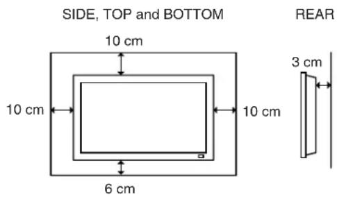
● Take appropriate space on the top, sides and rear of the Plasma Monitor cabinet for allowing air circulation and cooling the Plasma Monitor. Minimum clearance must be maintained. If the Plasma Monitor is to be built into
a compartment or similarly enclosed, the minimum distances must be maintained. Do not cover the ventilation slot on the Plasma Monitor. Heat build-up can reduce the life of your Plasma Monitor, and can also be dangerous.
- If the Plasma Monitor is not to be used for an extended time, unplug the Plasma Monitor from the power outlet.
READ AND KEEP THIS OWNER'S MANUAL FOR LATER USE.

CAUTION IN INSTALLING
● Handle the Plasma Monitor carefully when installing it and do not drop.
- Locate set away from heat, excessive dust, and direct sunlight.
- For correct installation and mounting it is strongly recommended to use a trained, authorized dealer. Failure to follow correct mounting procedures could result in damage to the equipment or injury to the installer.
NOTE :
When Plasma Monitor is not used for a long period of time, unlighting dots may be observed. This is caused by characteristic of the Plasma Monitor. If this occurs, turn the Plasma Monitor on and leave it on about 1 hour. These dots will gradually disappear.
CAUTION
RISK OF ELECTRIC SHOCK
DO NOT OPEN

CAUTION : TO REDUCE THE RISK OF ELECTRIC SHOCK, DO NOT REMOVE COVER (OR BACK). NO USER-SERVICEABLE PARTS INSIDE. REFER SERVICING TO QUALIFIED SERVICE PERSONNEL.

THIS SYMBOL INDICATES THAT DANGEROUS VOLTAGE CONSTITUTING A RISK OF ELECTRIC SHOCK IS PRESENT WITHIN THIS UNIT.

THIS SYMBOL INDICATES THAT THERE ARE IMPORTANT OPERATING AND MAINTENANCE INSTRUCTIONS IN THE OWNER'S MANUAL WITH THIS UNIT.
Read these instructions.
Keep these instructions.
Heed all warnings.
Follow all instructions.
Do not use this apparatus near water.
Clean only with dry cloth.
Do not block any ventilation openings. Install in accordance with the manufacturer's instructions.
Do not install near any heat sources such as radiators, heat registers, stoves, or other apparatus (including amplifiers) that produce heat.
Do not defeat the safety purpose of the polarized or grounding-type plug. A polarized plug has two blades with one wider than the other. A grounding type plug has two blades and a third grounding prong. The wide blade or the third prong are provided for your safety. If the provided plug does not fit into your outlet, consult an electrician for replacement of the obsolete outlet.
Protect the power cord from being walked on or pinched particularly at plugs, convenience receptacles, and the point where they exit from the apparatus.
Only use attachments/accessories specified by the manufacturer.
Use only with the car, stand, tripod, bracket, or table specified by the manufacturer, or sold with the apparatus. When a cart is used, use caution when moving the cart/apparatus combination to avoid injury from tip-over.
Unplug this apparatus during lighting storms or when unused for long periods of time.
Refer all servicing to qualified service personnel. Servicing is required when the apparatus has been damaged in any way, such as power-supply cord or plug is damages, liquid has been spilled or objects have fallen into the apparatus, the apparatus has been exposed to rain or moisture, does not operate normally, or has been dropped.
CAUTION:
This Plasma Monitor for use only with following Stand and Mount Unit. Use with other stands or mount units is capable of resulting in instability causing possible injury.
SANYO Table top stand KA-TD-42V
SANYO Tilt mount unit KA-TI-42V
SANYO Wall mount unit KA-WA-42V
An appliance and cart combination should be moved with care. Quick stops, excessive force, and uneven surfaces may cause the appliance and cart combination to overturn.

Slots and openings in the back and top of the cabinet are provided for ventilation, to insure reliable operation of the equipment and to protect it from overheating.
Never push objects of any kind into this Plasma Monitor through cabinet slots as they may touch dangerous voltage points or short out parts that could result in a fire or electric shock. Never spill liquid of any kind on the Plasma Monitor.
This Plasma Monitor should be operated only from the type of power source indicated on the marking label. If you are not sure of the type of power supplied, consult your authorized dealer or local power company.
Do not attempt to service this Plasma Monitor yourself as opening or removing covers may expose you to dangerous voltage or other hazards. Refer all servicing to qualified service personnel.
Unplug this Plasma Monitor from wall outlet and refer servicing to qualified service personnel under the following conditions:
a. When the power cord or plug is damaged or frayed.
b. If liquid has been spilled into the Plasma Monitor.
c. If the Plasma Monitor has been exposed to rain or water.
d. If the Plasma Monitor does not operate normally by following the operating instructions. Adjust only those controls that are covered by the operating instructions as improper adjustment of other controls may result in damage and will often require extensive work by a qualified technician to restore the Plasma Monitor to normal operation.
e. If the Plasma Monitor has been dropped or the cabinet has been damaged.
f. When the Plasma Monitor exhibits a distinct change in performance-this indicates a need for service.
When replacement parts are required, be sure the service technician has used replacement parts specified by the manufacturer that have the same characteristics as the original part. Unauthorized substitutions may result in fire, electric shock, or injury to persons.
Upon completion of any service or repairs to this Plasma Monitor, ask the service technician to perform routine safety checks to determine that the Plasma Monitor is in safe operating condition.
European Norm Compatibility / CE
This machine is provided with the CE-mark and therewith corresponding to the norms that are valid for its operation at present. Thus the effective guidelines on the electromagnetic compatibility 89/336/EWG and safety regulations according to low voltage guideline 73/23/EWG and 93/68/EWG are guaranteed. Mutual disturbances with other electronic appliances are normally excluded, if those also are in accordance with valid norms. Sporadically disturbances cannot, however, be excluded. The product is in conformity with the directives of the valid European guidelines.
Declaration of Conformity
This equipment has been tested and found to comply with the limits for a Class A digital device, pursuant to part 15 of the FCC Rules. These limits are designed to provide reasonable protection against harmful interference when the equipment is operated in a commercial environment. This equipment generates, uses, and can radiate radio frequency energy and, if not installed and used in accordance with the instruction manual, may cause harmful interference to radio communications. Operation of this equipment in a residential area is likely to cause harmful interference in which case the user will be required to correct the interference at his own expense.
AC POWER CORD REQUIREMENT
The AC Power Cord supplied with this Plasma Monitor meets the requirement for use in the country you purchased it.
AC Power Cord for the United States and Canada :
AC Power Cord used in the United States and Canada is listed by the Underwriters Laboratories (UL) and certified by the Canadian Standard Association (CSA).
AC Power Cord has a grounding-type AC line plug. This is a safety feature to be sure that the plug will fit into the power outlet. Do not try to defeat this safety feature. Should you be unable to insert the plug into the outlet, contact your electrician.

AC Power Cord for the United Kingdom :
This cord is already fitted with a moulded plug incorporating a fuse, the value of which is indicated on the pin face of the plug. Should the fuse need to be replaced, an ASTA approved BS 1362 fuse must be used of the same rating, marked thus ◆ If the fuse cover is detachable, never use the plug with the cover omitted. If a replacement fuse cover is required, ensure it is of the same colour as that visible on the pin face of the plug (i.e. red or orange). Fuse covers are available from the Parts Department indicated in your User Instructions.
If the plug supplied is not suitable for your socket outlet, it should be cut off and destroyed.
The end of the flexible cord should be suitably prepared and the correct plug fitted. (See Over)
WARNING : A PLUG WITH BARED FLEXIBLE CORD IS HAZARDOUS IF ENGAGED IN A LIVE SOCKET OUTLET.
The Wires in this mains lead are coloured in accordance with the following code:
Green-and-yellow .... Earth
Blue ...... Neutral
Brown Live
As the colours of the wires in the mains lead of this apparatus may not correspond with the coloured markings identifying the terminals in your plug proceed as follows:
The wire which is coloured green-and-yellow must be connected to the terminal in the plug which is marked by the letter E or by the safety earth symbol or coloured green or green-and-yellow.
The wire which is coloured blue must be connected to the terminal which is marked with the letter N or coloured black.
The wire which is coloured brown must be connected to the terminal which is marked with the letter L or coloured red.
WARNING : THIS APPARATUS MUST BE EARTHED.
THE SOCKET-OUTLET SHOULD BE INSTALLED NEAR THE EQUIPMENT AND EASILY ACCESSIBLE.
PREPARATION 6
NAME OF EACH PART OF PLASMA MONITOR 6 SETTING-UP PLASMA MONITOR 8
CONNECTING PLASMA MONITOR 11
TERMINALS OF PLASMA MONITOR 11 CONNECTING TO COMPUTER 12
BEFORE OPERATION 13
CLEANING PLASMA MONITOR 32 FUNCTIONS OF PRODUCT SAFETY FEATURES 32 TROUBLESHOOTING 33 TECHNICAL SPECIFICATIONS 35
TRADEMARKS
● Apple, Macintosh, and PowerBook are trademarks or registered trademarks of Apple Computer, Inc.
● IBM and PS/2 are trademarks or registered trademarks of International Business Machines, Inc.
● Each name of corporations or products in the owner's manual is a trademark or a registered trademark of its respective corporation.
CARE FOR USING PLASMA MONITOR
- Do not bump or scratch the panel surface as this causes flaws on the surface of the screen.
- Do not display one non-movement still picture on the screen for a long time. Otherwise, an afterimage or ghost may appear on a part of the panel. To prevent this symptoms, apply the screen saver function in the Plasma Monitor.
- There may be some tiny black points and/or blight points on the Plasma Display Panel. These points are normal.
NAME OF EACH PART OF PLASMA MONITOR
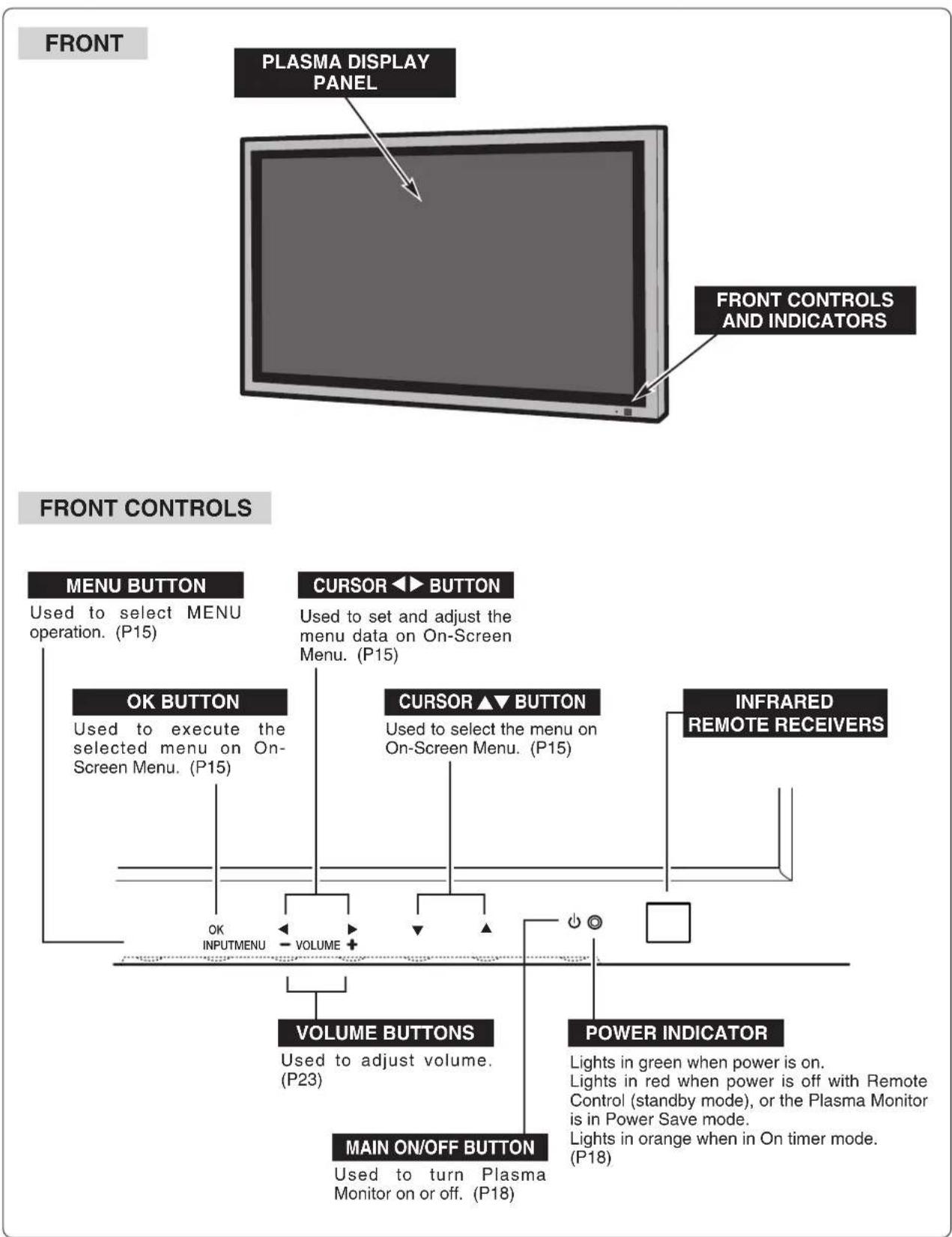
NAME OF EACH PART OF PLASMA MONITOR
BACK
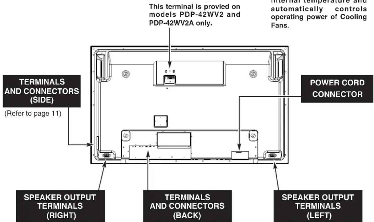
(Refer to page 11)
NOTES ON USING PLASMA MONITOR
For using this Plasma Monitor, Optional Stand or Mounting Bracket is needed. Those optional units are not included within this Monitor Set. Your Sales dealer can advice you of best optional unit for using Plasma Monitor. Contact your sales dealer for detail.
INSTALL PLASMA MONITOR IN PROPER DIRECTION
This Plasma Monitor can be installed in two ways, normal (horizontal) and vertical.
CAUTION:
DO NOT INSTALL UNSPECIFIED DIRECTION, OR COOLING AIR CIRCULATION IS PREVENTED AND IT MAY RESULT IN FIRE HAZARD.
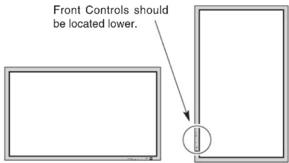
Horizontal
Vertical
SETTING-UP PLASMA MONITOR
CONNECTING AC POWER CORD
This Plasma Monitor uses nominal input voltages of 100-120 V or 200-240 V AC. The Plasma Monitor automatically selects the correct input voltage. It is designed to work with single-phase power systems having a grounded neutral conductor. To reduce the risk of electrical shock, do not plug into any other type of power system.
Consult your authorized dealer or service station if you are not sure of the type of power supply being in use.
Connect Plasma Monitor with the peripheral equipment before turning Plasma Monitor on. (Refer to page 12 for connection.)

CAUTION
For safety, unplug the AC Power Cord when the appliance is not used.
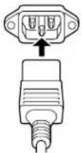
Connect AC Power Cord (supplied) to Plasma Monitor.
The AC outlet must be near this equipment and must be easily accessible.

natural_image
Diagram of a plug with two ports and an arrow pointing to the top port (no text or labels)| NOTE ON THE POWER CORDThe AC Power Cord must meet the requirement of the country where you use the Plasma Monitor. Confirm the AC plug type with the chart below and the proper AC Power Cord must be used.If the supplied AC Power Cord does not match the AC outlet, contact your sales dealer. | |||
| Plasma Monitor side | AC Outlet side | ||
 To the POWER CORD CONNECTOR on Plasma Monitor To the POWER CORD CONNECTOR on Plasma Monitor | For the U.S.A. and Canada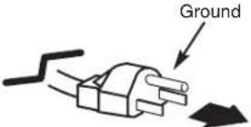 To the AC Outlet.(120 V AC) To the AC Outlet.(120 V AC) | For Continental Europe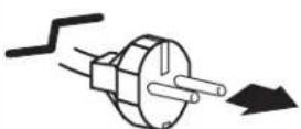 To the AC Outlet.(220 - 240 V AC) To the AC Outlet.(220 - 240 V AC) | For the U.K.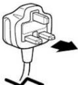 To the AC Outlet.(220 - 240 V AC) To the AC Outlet.(220 - 240 V AC) |
INSTALLATION OF OPTIONAL SPEAKERS AND STAND
Please read the each option's instruction manual (or installation manual) for the installation.

CAUTION IN INSTALLATION
● Through installation work, handling with more than two people is recommended.
- When holding (moving or lifting) the Plasma Monitor, hold the Monitor's body. Do not handle it by holding the attached accessory parts (the Speakers), otherwise damage could be result.
- Provide space that enough larger than the screen size. The surface must be flat and maintained with soft material (cloth or blanket) for protecting the screen surface.
- Before placing the Plasma Monitor Screen facing down, make sure there is no object under the screen. Leaving any object may cause damage on the screen surface.
SPEAKERS (OPTIONAL)
Place the Plasma Display screen facing down on a flat surface place where maintained with soft materials (such as a blanket) for protecting the display screen. Loosen the screws A of the Plasma Display.
Place the Speakers where each soft-taped side comes next to each side of the Plasma Display, and attach 2 brackets for each Speaker with the large screws (2 pcs. for each bracket).
Loosen the screws A of the Plasma Display. With hooking the lower brackets to the screws A, tighten the small screws (1 pc. for each lower bracket) to fix the bracket and the Plasma Monitor. Be careful not to leave the space between the Speakers and the Plasma Display. Tighten the screws A.
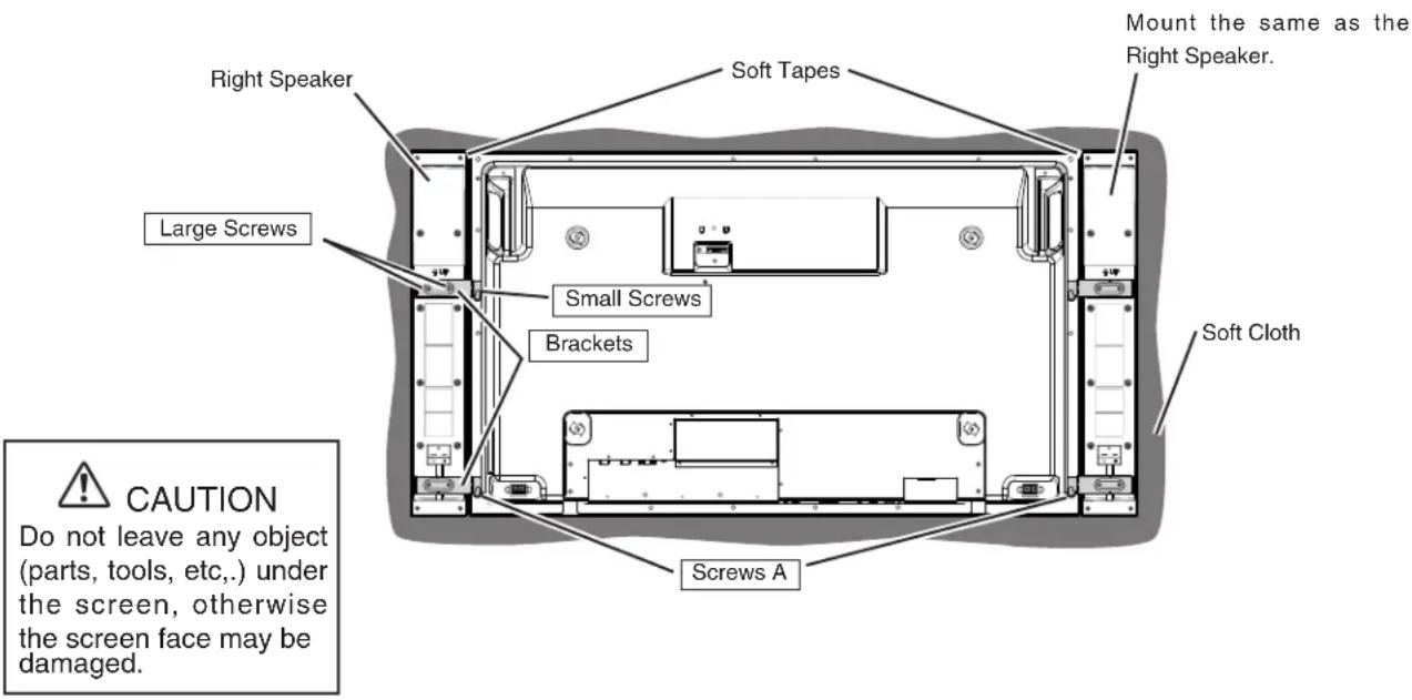
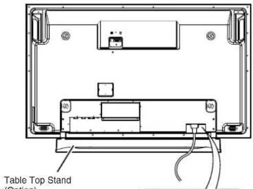
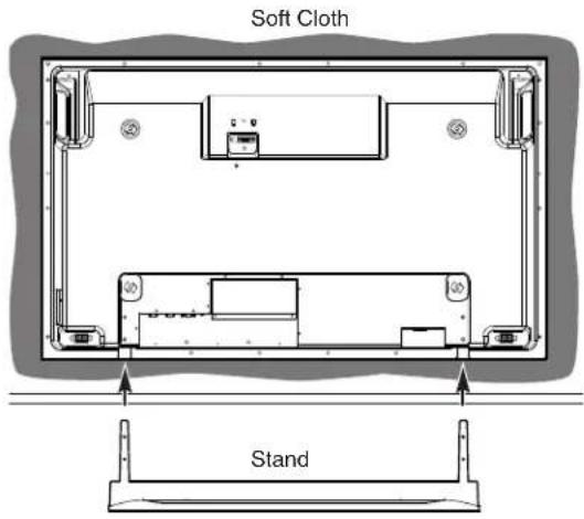
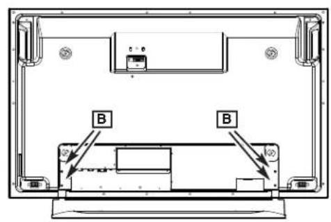
TABLE TOP STAND(OPTIONAL)
Assemble Table top stand according to the installation manual of the stand.
Place the Plasma Display screen facing down on a flat surface place where maintained with soft materials (such as a blanket) for protecting the display screen. Insert the Stand into the slot of the Plasma Display.
Fix the Plasma Display on the Stand with screws B (2 pcs. for each side).
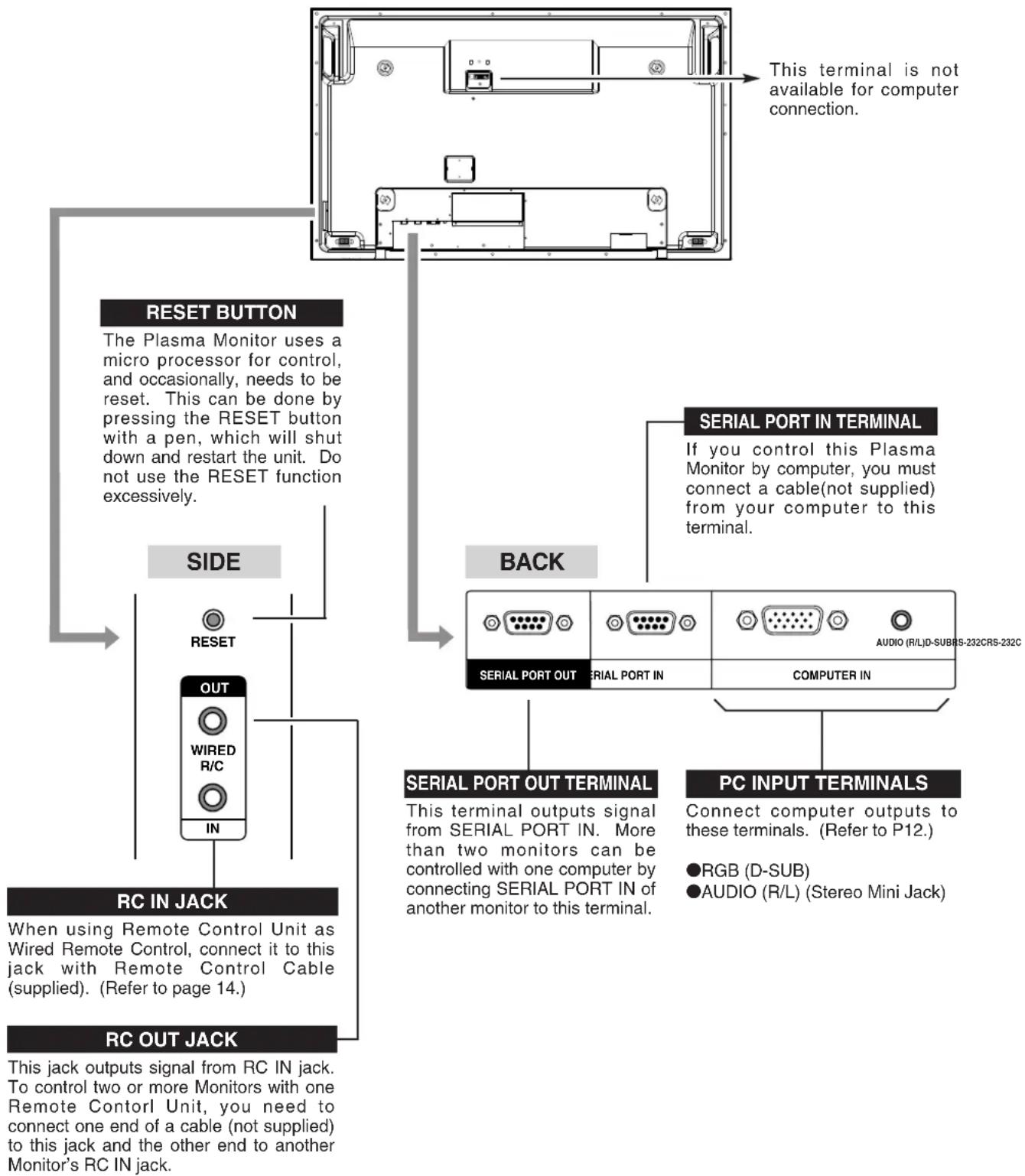
TERMINALS OF PLASMA MONITOR
This Plasma Monitor has INPUT TERMINALS and OUTPUT TERMINALS on its side and back, for connecting computers and video equipment. Refer to the figure on page 12 and connect properly.
flowchart
graph TD
    A["This terminal is not available for computer connection."] --> B["RESET BUTTON"]
    B --> C["SIDE"]
    C --> D["OUT"]
    D --> E["RC IN JACK"]
    E --> F["RC OUT JACK"]
    G["SERIAL PORT IN TERMINAL"] --> H["BACK"]
    H --> I["PC INPUT TERMINALS"]
    I --> J["SERIAL PORT OUT TERMINAL"]
    J --> K["COMPUTER IN"]
    K --> L["AUDIO (R/L)D-SUBHS-232CRS-232C"]
    M["When using Remote Control Unit as Wired Remote Control, connect it to this jack with Remote Control Cable (supplied). (Refer to page 14.)"] --> N["Reset"]
    O["When using Remote Control Unit as Wired Remote Control, connect it to this jack with Remote Control Cable (supplied). (Refer to page 14.)"] --> P["In"]
    Q["When using Remote Control Unit as Wired Remote Control, connect it to this jack with Remote Control Cable (supplied). (Refer to page 14.)"] --> R["WiRED R/C"]
    S["When using Remote Control Unit as Wired Remote Control, connect it to this jack with Remote Control Cable (supplied). (Refer to page 14.)"] --> T["RGB (D-SUB)"]
    U["When using Remote Control Unit as Wired Remote Control, connect it to this jack with Remote Control Cable (supplied). (Refer to page 14.)"] --> V["AUDIO (R/L) (Stereo Mini Jack)"]
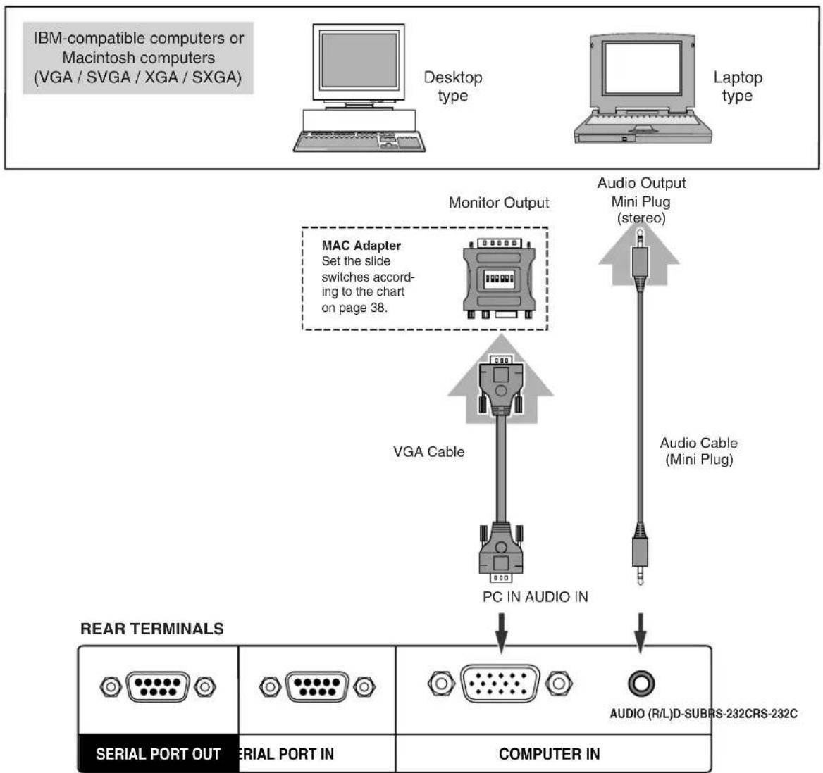
CONNECTING TO COMPUTER
Cables used for connection (Those Cables and Adapter are not supplied with this Plasma Monitor.)
• VGA Cable (HDB 15 pin)
• MAC Adapter (in the case of connecting Macintosh computer)
• Audio Cable ( Mini Plug - Mini Plug (R/L))
NOTE: We recommend you to use a cable shorter than 3m.

NOTE :
When connecting the cable, AC Power Cords of both Plasma Monitor and external equipment should be disconnected from AC outlet. Turn Plasma Monitor and peripheral equipment on before your computer is switched on.
flowchart
graph TD
    A["IBM-compatible computers or Macintosh computers (VGA / SVGA / XGA / SXGA)"] --> B["Desktop type"]
    A --> C["Laptop type"]
    B --> D["Monitor Output"]
    C --> E["Audio Output Mini Plug (stereo)"]
    D --> F["MAC Adapter Set the slide switches according to the chart on page 38."]
    E --> G["VGA Cable"]
    G --> H["PC IN AUDIO IN"]
    H --> I["REAR TERMINALS"]
    I --> J["SERIAL PORT OUT"]
    I --> K["SERIAL PORT IN"]
    I --> L["COMPUTER IN"]
    L --> M["AUDIO (R/L)D-SUBRS-232CRS-232C"]
Remote Control Unit can be used as either Wired or Wireless.
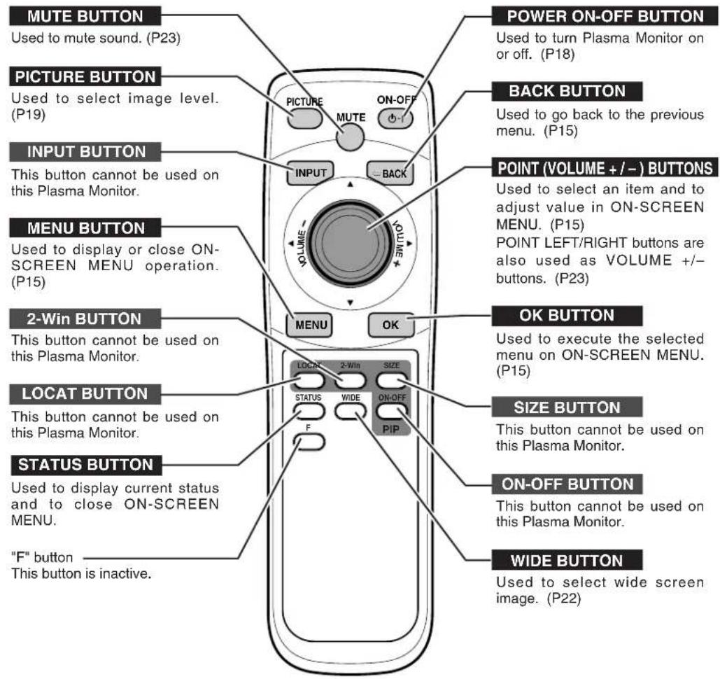
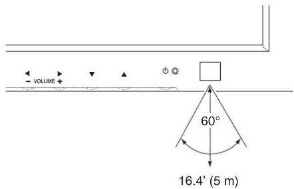
OPERATING RANGE
Point Remote Control toward Plasma Monitor (Remote Receiver) whenever pressing the buttons. Maximum operating range for Remote Control is about 16.4' (5m) and 60° in front of Plasma Monitor.
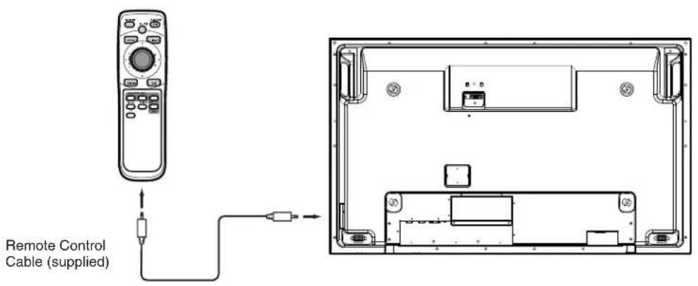
When using this Remote Control Unit as Wired Remote Control, Connect Remote Control Unit to R/C JACK with Remote Control Cable (supplied). Batteries installation is required when using as Wired Remote Control Unit.
NOTE: Wireless Remote Control does not work when Remote Control Cable is connected on Plasma Monitor or Remote Control.
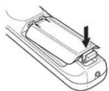
REMOTE CONTROL BATTERIES INSTALLATION
123 Remove the battery compartment lid.
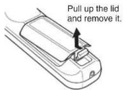
Slide the batteries into compartment.
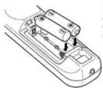
Two AA size batteries For correct polarity (+ and -), be sure battery terminals are in contact with pins in compartment.
Replace the compartment lid.

To insure safe operation, please observe the following precautions:
●Use (2) AA, UM3 or R06 type alkaline batteries.
●Replace two batteries at the same time.
●Do not use a new battery with a used battery.
●Avoid contact with water or liquid.
●Do not expose the remote control to moisture, or heat.
●Do not drop the remote control.
- If a battery has leaked on the remote control, carefully wipe case clean and install new batteries.
●Risk of explosion if battery is replaced by an incorrect type.
●Dispose of used batteries according to the instructions.
You can control and adjust this Plasma Monitor through ON-SCREEN MENU. Refer to the following pages to operate each adjustment on ON-SCREEN MENU.
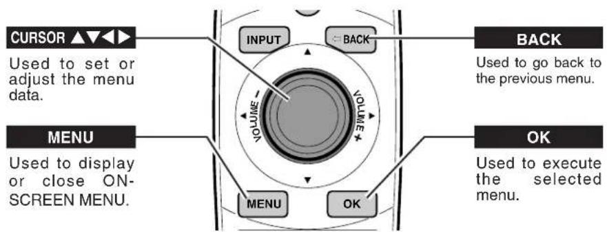
BUTTONS OF ON-SCREEN MENU OPERATION
REMOTE CONTROL UNIT
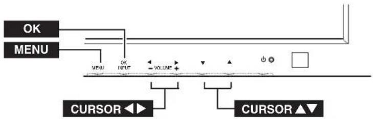
FRONT CONTROLS
flowchart
graph TD
    A["OK"] --> B["MENU"]
    C["CURSOR ◀"] --> D["INPUT"]
    E["VOLUME ▶"] --> F["POS"]
    G["CURSOR ▲"] --> H["▼"]
1 Press MENU button and ON-SCREEN MENU will appear.
2 Press ▲▼ buttons to select the menu that you want to adjust, and press OK button. The selected menu will appear.
3 Press ▲▼ buttons to select the item that you want to adjust.
4 Adjust the item by pressing ◀▶ buttons.
5 Press MENU button to close ON-SCREEN MENU.
MENU
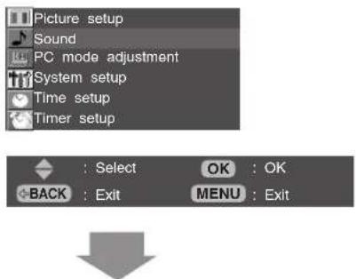
SOUND MENU (example)


MENU LIST
flowchart
graph TD
A["Picture setup"] --> B["Sound"]
A --> C["PC mode adjustment"]
A --> D["System setup"]
A --> E["Time setup"]
A --> F["Timer setup"]
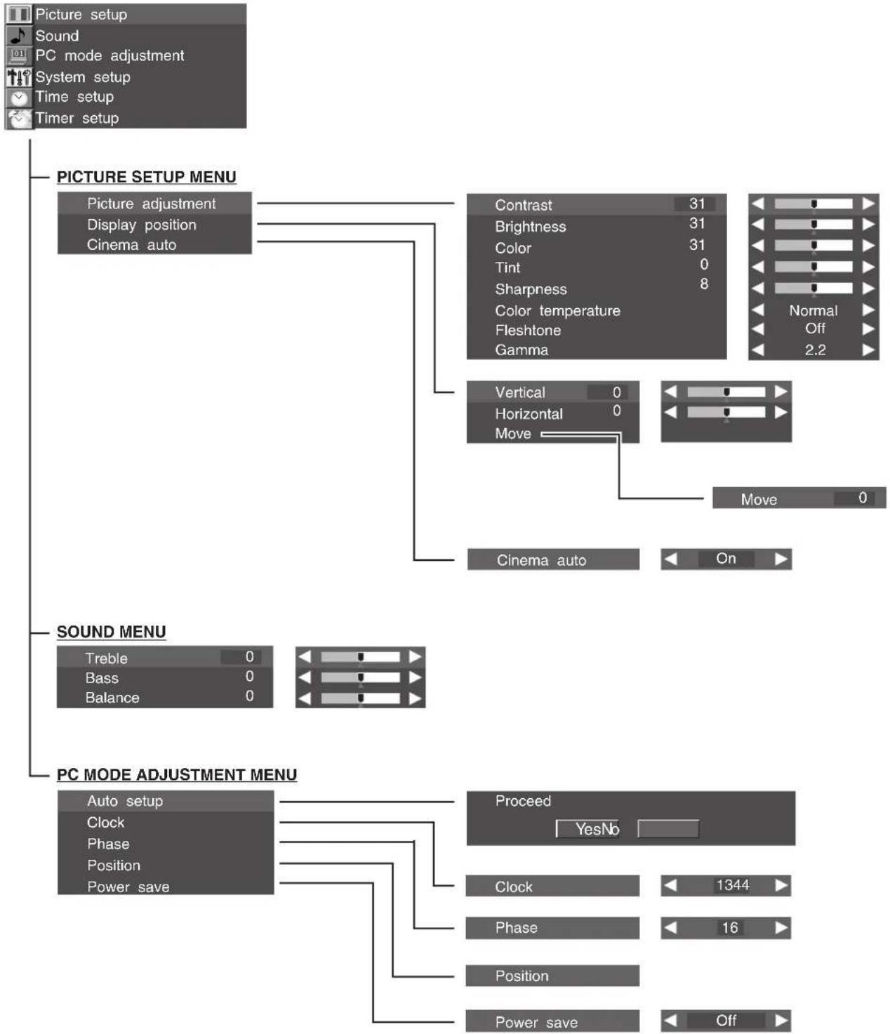
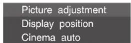
G["PICTURE SETUP MENU"] --> H["Picture adjustment"]
G --> I["Display position"]
G --> J["Cinema auto"]
K["SOUND MENU"] --> L["Treble 0"]
K --> M["Bass 0"]
K --> N["Balance 0"]
O["PC MODE ADJUSTMENT MENU"] --> P["Auto setup"]
O --> Q["Clock"]
O --> R["Phase"]
O --> S["Position"]
O --> T["Power save"]
U["Contrast 31"] --> V["Brightness 31"]
U --> W["Color 31"]
U --> X["Tint 0"]
U --> Y["Sharpness 8"]
Z["Vertical 0"] --> AA["Horizontal 0"]
AB["Move"] --> AC["Move 0"]
AD["Cinema auto"] --> AE["On"]
AF["Proceed YesNo"] --> AG["Clock 1344"]
AF --> AH["Phase 16"]
AF --> AI["Position"]
AF --> AJ["Power save Off"]
MENU LIST(Continue)
SYSTEM SETUP MENU
flowchart
graph TD
    A["Language"] --> B["Screen saver"]
    A --> C["Reset"]
    A --> D["Information"]
    E["English"] --> F["English"]
    G["PIC rotation"] --> H["Cycle time"]
    G --> I["Dot"]
    G --> J["White pattern"]
    G --> K["Interval"]
    G --> L["Display time"]
    G --> M["Side bar"]
    N["Return to factory settings"] --> O["YesNo"]
    P["Temperature: OK"] --> Q["Cooling fan : OK"]
    P --> R["Signal : PC"]
    P --> S["FH : 58.03 kHz"]
    P --> T["FV : 72.00 Hz"]
    U["TIME SETUP MENU"] --> V["Present time 12 : 30"]
    W["TIMER SETUP MENU"] --> X["On timer 08 : 30"]
    W --> Y["Time to turn on Off timer No 19 : 30"]
TURNING ON / OFF PLASMA MONITOR
1 Complete the peripheral connections (with Computer) before turning on Plasma Monitor. (Refer to "CONNECTING PLASMA MONITOR" on Page 12 for connecting that equipment.)
2 Connect the Plasma Monitor's AC Power Cord into an AC outlet.
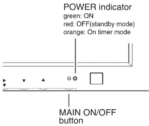
3 Press MAIN ON/OFF button on Front Control of Plasma Monitor to turn ON. POWER indicator will light up(green) when Plasma Monitor is ON. Press MAIN ON/OFF button again to turn OFF.
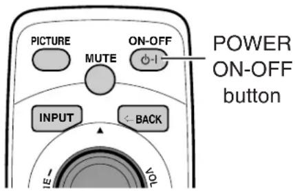
NOTE: When you are operating POWER ON-OFF button on Remote Control Unit, turn the Plasma Monitor ON with MAIN ON/OFF button on the Plasma Monitor first. This is the master switch of the Plasma Monitor. Remote Control Unit does not work if this switch is OFF. POWER indicator lights in red when Plasma Monitor power is OFF(standby mode) with Remote Control Unit.
4 When MAIN ON/OFF button on the Plasma Monitor is ON, you can turn power ON/OFF by POWER ON-OFF button on Remote Control Unit. When Plasma Monitor power is turned OFF with Remote Control Unit, POWER indicator lights in red (standby mode).
NOTE :
When "Power Save" function is set to "ON", Plasma Monitor detects signal interruption and turns off Plasma Monitor automatically. Refer to "Power Save" on page 26.
On-Screen display and On-Screen menu disappear after a short while for prevention of afterimage (ghost) on screen.
PICTURE IMAGE LEVEL SELECT
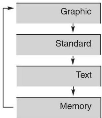
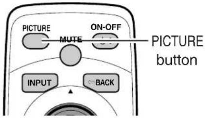
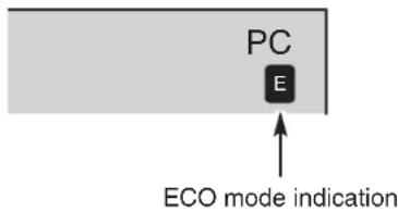
Select image level among Graphic, Standard, Text, and Memory by pressing PICTURE button on the Remote Control Unit.
Graphic
Select this mode when watching graphic image.
Standard
Normal picture level preset on this Plasma Monitor.
Text
Select this mode when watching text image.
Memory
User preset picture adjustment in image level adjustment (P20).
flowchart
graph TD
    A["Graphic"] --> B["Standard"]
    B --> C["Text"]
    C --> D["Memory"]
NOTE :
●By pressing PICTURE button on Remote Control Unit, ECO mode indication "E" (If ECO mode is "ECO1" or "ECO2") will be displayed. (Refer to page 28.)
IMAGE LEVEL ADJUSTMENT
1 Press MENU button and ON-SCREEN MENU will appear.
2 Press ▲▼ buttons to select "Picture setup" menu, and press OK button. "Picture setup" menu will appear.
3 Press ▲▼ buttons to select "Picture adjustment" menu, and press OK button. "Picture adjustment" menu will appear.
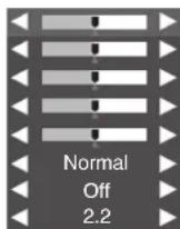
4 Press ▲▼ buttons to select the item you want to adjust; the level of selected item is displayed.
5 Adjust each level by pressing ◀▶ buttons.
Contrast
Press ◀ button to decrease contrast, and ▶ button to increase contrast.
Brightness
Press ◀ button to adjust image darker, and ▶ button to adjust brighter.
Color
Press ◀ button to lighter color, and ▶ button to darker color.
Tint
Press ◀▶ button to obtain proper color.
Sharpness
Press ◀ button to soften the image, and ▶ button to sharpen the image.
Color temperature
This function is used for selecting color temperature. Select "Normal", "Cool" or "Warm" with ◀▶ buttons which you wish to select.
Fleshtone
When this function is "ON", it produces a more vivid image according to the image condition.
Gamma
Press ◀▶ button to obtain a better balance of the contrast.
PICTURE SETUP MENU
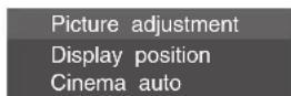


PICTURE ADJUSTMENT MENU
| Contrast | 31 |
| Brightness | 31 |
| Color | 31 |
| Tint | 0 |
| Sharpness | 8 |
| Color temperature | |
| Fleshtone | |
| Gamma |

NOTE :
●Cinema auto cannot be selected on this model.
WIDE IMAGE ADJUSTMENT
1 Press MENU button and ON-SCREEN MENU will appear.
2 Press ▲▼ buttons to select "Picture setup" menu, and press OK button. "Picture setup" menu will appear.
3 Press ▲▼ buttons to select "Display position" menu, and press OK button. "Display position" menu will appear.
4 Press ▲▼ buttons to choose either "Vertical" or "Horizontal", and adjust image by pressing ◀▶ buttons.
PICTURE SETUP MENU

Vertical
Adjustment of height of image.
Horizontal
Adjustment of horizontal expand proportion on both sides of image.
5 Press ▲▼ buttons to select "Move", and adjust the vertical position of the screen image by pressing ▲▼ buttons.
Move
Adjustment of vertical position of image.
DISPLAY POSITION MENU


NOTE :
● "Display position" menu cannot be opened when wide image mode is "Full" or "Normal".
●Horizontal can be adjusted only when wide image mode is "Natural wide".
●Move cannot be adjusted on this model.
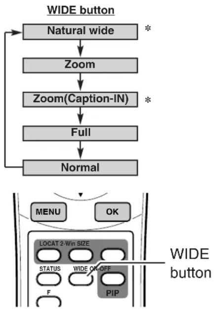
Select screen size among "Natural wide", "Zoom", "Zoom(Caption-IN)", "Full" and "Normal" by pressing WIDE button on Remote Control Unit.
* "Natural wide" or "Zoom(Caption-IN)" mode cannot be selected on this model.
Note: Only "Full" is selected when input signal is "720p" or "1080i".
flowchart
graph TD
    A["WIDE button"] --> B["Natural wide"]
    B --> C["Zoom"]
    C --> D["Zoom(Caption-IN)"]
    D --> E["Full"]
    E --> F["Normal"]
    F --> G["+"]
    G --> H["+"]
    H --> I["+"]
    I --> J["+"]
    J --> K["+"]
    K --> L["+"]
    L --> M["+"]
    M --> N["+"]
    N --> O["+"]
    O --> P["+"]
    P --> Q["+"]
    Q --> R["+"]
    R --> S["+"]
    S --> T["+"]
    T --> U["+"]
    U --> V["+"]
    V --> W["+"]
    W --> X["+"]
    X --> Y["+"]
    Y --> Z["+"]
    Z --> AA["+"]
    AA --> AB["+"]
    AB --> AC["+"]
    AC --> AD["+"]
    AD --> AE["+"]
    AE --> AF["+"]
    AF --> AG["+"]
    AG --> AH["+"]
    AH --> AI["+"]
    AI --> AJ["+"]
    AJ --> AK["+"]
    AK --> AL["+"]
    AL --> AM["+"]
    AM --> AN["+"]
    AN --> AO["+"]
    AO --> AP["+"]
    AP --> AQ["+"]
    AQ --> AR["+"]
    AR --> AS["+"]
    AS --> AT["+"]
    AT --> AU["+"]
    AU --> AV["+"]
    AV --> AW["+"]
    AW --> AX["+"]
    AX --> AY["+"]
Natural wide
Provides image to fit width of screen by expanding both sides of image. This function is suitable to enjoy a normal video signal (4 : 3 aspect ratio) with wide video aspect ratio of 16 : 9 screen.
Zoom
Provides image to fit screen size (16 : 9 aspect ratio) by expanding image width and height uniformly. This function can be used for enjoying a letter box mode picture (4 : 3 aspect picture with black bar on top and bottom edges) with wide video aspect of 16 : 9 screen.
Zoom (Caption-IN)
Provides the image that is expanded as "Zoom" mode and moved up to show more image to include captions. This function can be used for enjoying a letter box picture with captions.
Full
Provides image to fit width of screen by expanding image width uniformly. This function can be used for enjoying a squeezed video signal with wide video aspect ratio of 16:9 screen.
When your video equipment (such as DVD) has 16 : 9 output mode, select 16 : 9 and select Full on this SCREEN Menu to provide better quality.
Normal
Provides real 4 : 3 image on 16 : 9 screen.

natural_image
Two sequential illustrations showing a golfer performing a swing pose, with no text or symbols present.

natural_image
Illustration of a person tying a rope knot, showing the motion before and after (no text or symbols)
natural_image
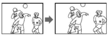
Two sequential illustrations showing a person in a baseball stance, before and after a change (no text or symbols present)SOUND ADJUSTMENT
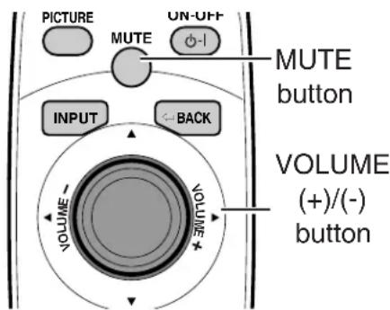
VOLUME
Press VOLUME (+/-) button(s) on Remote Control Unit or Front Control to adjust volume. Volume dialog box appears on the screen for a few seconds.
(+) button to increase volume, and (−) button to decrease volume.
MUTE
Press MUTE button on Remote Control Unit to cut off sound. To restore sound to its previous level, press MUTE button again or press VOLUME (+/-) button(s).


SOUND ADJUSTMENT
1 Press MENU button and ON-SCREEN MENU will appear.
2 Press ▲▼ buttons to select "Sound" menu, and press OK button. "Sound" menu will appear.
3 Press ▲▼ buttons to select the item that you want to adjust, and make adjustment by pressing ◀▶ buttons.
SOUND MENU


Treble
Press ◀ button to decrease high frequency sound, and ▶ button to increase high frequency sound.
Bass
Press ◀ button to decrease low frequency sound, and ▶ button to increase low frequency sound.
Balance
Adjusts the balance of the left and right channels.
SELECTING COMPUTER SYSTEM
This Plasma Monitor automatically tunes to most different types of computers based on VGA, SVGA, XGA or SXGA (refer to "COMPATIBLE COMPUTER SPECIFICATIONS" on page 27). When selecting Computer, this Plasma Monitor automatically tunes to incoming signal and display proper image without any special setting. (Some computers need setting manually.) If the Monitor cannot be tuned, follow in message will be displayed.
Out of scan range
When Plasma Monitor cannot recognize connected signal that PC system provides in the message "Out of scan range" is displayed on screen.
No signal
There is no signal input from computer. Make sure the connection of computer and Plasma Monitor is set correctly.
PC ADJUSTMENT
PC MODE ADJUSTMENT
"PC mode adjustment" menu is provided to adjust "Auto setup", "Clock", "Phase", "Position" and "Power save" to conform to your computer. These function can be operated as follows:
1 Press MENU button and ON-SCREEN MENU will appear.
2 Press ▲▼ buttons to select "PC mode adjustment" menu, and press OK button. "PC mode adjustment" menu will appear.
3 Press ▲▼ buttons to select the item that you want to adjust, and press OK button. The selected item will appear.
4 Adjust each level by pressing ◀▶ buttons.
PC MODE ADJUSTMENT MENU
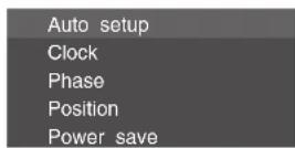

Auto setup
This function automatically adjusts "Clock", "Phase" and "Position" to conform to your computer.
To execute this function, press ◀▶ buttons to select "Yes", and press OK button.
NOTE :
- In the following cases, the Plasma Monitor may not adjust itself with this function.
1) If the picture is not displayed fully on the screen.
2) When a contrast picture, such as an outdoor scene, is displayed on the screen. - Depending on signal and computer's configuration, this function cannot be operated properly. In this case, adjust "Clock", "Phase" and "Position" manually.
Clock
Adjust when Vertical noise lines are observed.
(Horizontal width will be changed by adjustment.)
Adjust with ◀▶ buttons.
Phase
Adjust when Horizontal noise lines are observed.
Adjust with ◀▶ buttons.
NOTE : This adjustment may be needed when a image becomes unclear or flickering.
Position
Adjusts the screen position.
Adjust with ▲▼◀▶ buttons.


Power save
Enable or disable Power save function.
Enable Power save by choosing "ON" with
◀▶ buttons.
NOTE :
- This function automatically reduces the Plasma Monitor's power consumption if the computer is not operated for a certain period of time. This function can be used when using the Plasma Monitor with a computer conforming to the VESA DPMS standard.
- To activate this function, computer setup is also needed. (Refer to Computer Operation manual.)
Power save

Off


←BACK
: Select
: Back
MENU
Exit
COMPATIBLE COMPUTER SPECIFICATIONS
This Plasma Monitor can accept the signal from all computers with the V, H-Frequency mentioned below and less than 140 MHz of Dot Clock.
| ON-SCREEN DISPLAY | RESOLUTION | H-Freq. (kHz) | V-Freq. (Hz) | ON-SCREEN DISPLAY | RESOLUTION | H-Freq. (kHz) | V-Freq. (Hz) |
| VGA 1 640 x 480 31.47 59.88 | XGA 10 1024 x 768 | 62.04 77.07 | |||||
| VGA 3 640 x 400 31.47 70.09 | XGA 11 1024 x 768 | 61.00 75.70 | |||||
| VGA 4 640 x 480 37.86 74.38 | XGA 13 1024 x 768 | 46.90 58.20 | |||||
| VGA 5 640 x 480 37.86 72.81 | XGA 14 1024 x 768 | 47.00 58.30 | |||||
| VGA 6 640 x 480 37.50 75.00 | XGA 15 1024 x 768 | 58.03 72.00 | |||||
| VGA 7 640 x 480 43.269 85.00 | MAC 19 1024 x 768 60.24 | 75.08 | |||||
| MAC LC13 | 640 x 480 34.97 66.60 | MAC 21 | 1152 x 870 | 68.68 75.06 | |||
| MAC 13 640 x 480 35.00 66.67 | SXGA 2 1280 x 1024 | 62.50 58.60 | |||||
| RGB | —— | 15.625 | ^50 (Interlace) | SXGA 3 1280 x 1024 | 63.90 60.00 | ||
| RGB | —— | 15.734 | ^60 (Interlace) | SXGA 4 1280 x 1024 | 63.34 59.98 | ||
| SVGA 1 800 x 600 35.156 | 56.25 | SXGA 5 1280 x 1024 | 63.74 60.01 | ||||
| SVGA 2 800 x 600 37.88 60.32 | SXGA 6 1280 x 1024 | 71.69 67.19 | |||||
| SVGA 3 800 x 600 46.875 | 75.00 | SXGA 7 1280 x 1024 | 81.13 76.107 | ||||
| SVGA 4 800 x 600 53.674 | 85.06 | SXGA 8 1280 x 1024 | 63.98 60.02 | ||||
| SVGA 5 800 x 600 48.08 | 72.19 | SXGA 9 1280 x 1024 | 79.976 75.025 | ||||
| SVGA 6 800 x 600 37.90 | 61.03 | SXGA 10 1280 x 960 | 60.00 60.00 | ||||
| SVGA 7 800 x 600 34.50 | 55.38 | SXGA 11 1152 x 900 | 61.20 65.20 | ||||
| SVGA 8 800 x 600 38.00 | 60.51 | SXGA 12 1152 x 900 | 71.40 75.60 | ||||
| SVGA 9 800 x 600 38.60 | 60.31 | SXGA 15 1280 x 1024 | 63.37 60.01 | ||||
| SVGA 10 800 x 600 32.70 | 51.09 | SXGA 16 1280 x 1024 | 76.97 72.00 | ||||
| MAC 16 832 x 624 49.72 | 74.55 | SXGA 17 1152 x 900 | 61.85 66.00 | ||||
| XGA 1 1024 x 768 | 48.36 60.00 | SXGA 19 1280 x 1024 63.79 | 60.18 | ||||
| XGA 2 1024 x 768 | 68.677 84.997 | MAC 1280 x 960 75.00 | 75.08 | ||||
| XGA 3 1024 x 768 | 60.023 75.03 | MAC 1280 x 1024 80.00 | 75.08 | ||||
| XGA 4 1024 x 768 | 56.476 70.07 | 720p (HDTV) | —— | 45.00 60.00 | |||
| XGA 5 1024 x 768 60.31 | 74.92 | 1080i (HDTV) | —— | 33.75 | ^60.00 (Interlace) | ||
| XGA 6 1024 x 768 | 48.50 60.02 | ||||||
| XGA 8 | 1024 x 768 | 63.48 | 79.35 | ||||
NOTE :
The image data from connected computer is modified to fit the Plasma Monitor's screen size.
Specifications are subject to change without notice.
SETTING MENU
1 Press MENU button and ON-SCREEN MENU will appear.
2 Press ▲▼ buttons to select "System setup", and press OK button. "System setup" will appear.
3 Press ▲▼ buttons to select the item that you want to setup, and setup the selected item by pressing ◀▶ buttons.
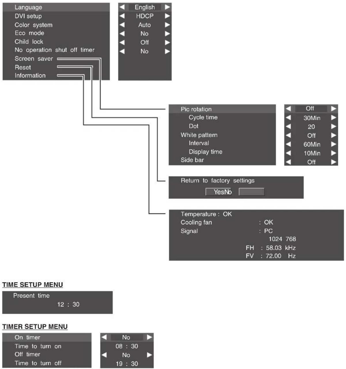
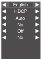
Language
Select language by pressing ◀▶ buttons among English, French, German, Italian, Spanish, Chinese and Japanese.
DVI
This function cannot be selected on this model.
Color system
This function cannot be selected on this model.
ECO mode
This function reduces the power consumption of the Plasma Monitor, and screen brightness goes down. "ECO1" is less power reduction than "ECO2".
Press ◀▶ buttons to select "ECO1", "ECO2", or "No".
NOTE :
In "ECO1" or "ECO2" mode,
- By pressing STATUS button on Remote Control Unit, Input source, Present time and ECO mode indication "E" will be displayed for 5 seconds.
●By pressing PICTURE button on Remote Control Unit, ECO mode indication "E" will be displayed.
Child lock
This function locks current control settings so that they cannot be inadvertently changed. With "Child lock-On", Plasma Monitor's front control buttons will be locked.
Remote Control Unit buttons can be operated under "Child lock-On".
No operation shut off timer
This function turns off Plasma Monitor's power automatically when there is no operation of Remote Control or Front Control for 3 hours. When this function is "Yes", if there is no operation for 3 hours, the message "No operation: Power off" will be displayed for about 1 minute, and Plasma Monitor's power will be turned off automatically.
Screen saver
Refer to "SCREEN SAVER FUNCTION". (P30)
SYSTEM SETUP MENU
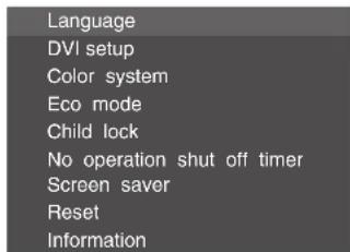

Reset
All adjustments in the memory can be reset to factory-settings.
1) Press OK button. Reset menu will appear.
2) Press ◀▶ buttons to select "Yes", and press OK button. All adjustments in the memory is reset to factory-settings.
Information
This function displays the condition of internal temperature, condition of cooling fan, and input signal information.
Press OK button. Information menu will appear.
When "Temperature" or "Cooling fan" is displayed "NG", turn Plasma Monitor off and contact sales dealer where you purchased the Plasma Monitor or the service center.
Return to factory settings
YesNo


← BACK
: Select
Back

MENU
OK
Exit
Temperature: OK
Cooling fan
Signal
:OK
:PC
1024 768
FH : 58.03 kHz
FV : 72.00 Hz
← BACK
Back
MENU
Exit
SCREEN SAVER FUNCTION
Displaying a still picture (non-movement) on the screen for a long time cause afterimage (ghost) on the screen. To neutralized the remaining image, Screen Saver function (3 modes) is provided in the Monitor. Use the function conveniently.
SELECTING SCREEN SAVER
1 Press MENU button and ON-SCREEN MENU will appear.
2 Press ▲▼ buttons to select "System setup", and press OK button. "System setup" will appear.
3 Press ▲▼ buttons to select "Screen saver", and press OK button. "Screen saver" menu will appear.
4 Press ▲▼ buttons to select the screen saver : "Pic rotation" or "White pattern". Press ◀▶ buttons to select "ON".
NOTE : Priority is given to the "Power save" function when the "Power save" function is set as "ON".
SCREEN SAVER MENU
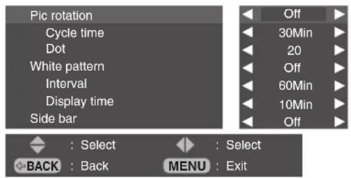
PICTURE ROTATION
The screen saver "Pic rotation" automatically changes display position.
1 In the "Screen saver" menu ("Pic rotation"), press ▲▼ buttons to select "Cycle time", and press ◀▶ buttons to select desired cycle time.
Cycle time : 15 / 30 / 60 (Min)
2 Press ▲▼ buttons to select "Dot", and press ◀▶ buttons to select moving distance.
Dot: 5 / 10 / 20 (dots)
WHITE PATTERN
The screen saver "White pattern" displays white pattern.
1 In the "Screen saver" menu ("White pattern"), press ▲▼ buttons to select "Interval (time)", and press ◀▶ buttons to select desired interval time. Interval (time) : 30 / 60 / 90 / 0 (Min)
When the interval time is set at "0", the white pattern displayed all the time.
2 Press ▲▼ buttons to select "Display time", and press ◀▶ buttons to select display time (White screen display time). Display time : 5 / 10 (Min)
SIDE BAR
When 4 : 3 image of screen saver is displayed for a long period of time, the 4 : 3 image and black bars on side will remain as the burning image. "Side bar" function changes the black bars into gray and the burning image can be neutralized.
In the "Screen saver" menu, press ▲▼ buttons to select "Side bar", and press ◀▶ buttons to select "On" or "Off".
NOTE : This function works only when 4 : 3 signal is provided.
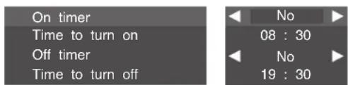
SET CLOCK
1 Press MENU button and ON-SCREEN MENU will appear.
2 Press ▲▼ buttons to select "Time setup", and press OK button. "Time setup" will appear.
3 To set the hours, press ▲▼ buttons. To set the minutes, press ▶ button once, and press ▲▼ buttons. Press OK button to set the time.
TIME SETUP MENU


ON/OFF TIMER
1 Press MENU button and ON-SCREEN MENU will appear.
2 Press ▲▼ buttons to select "Timer setup", and press OK button. "Timer setup" will appear.
3 Press ▲▼ buttons to select the timer : "On timer" or "Off timer", and press ◀▶ buttons to select "Yes". Press ▲▼ button to select the time: "Time to turn on" or "Time to turn off", and press OK button. Selected time menu will appear.
4 Press ▲▼ buttons to set the hours. To set the minutes, press ▶ button once, and press ▲▼ buttons. When finished, press OK button.
TIMER SETUP MENU

CLEANING PLASMA MONITOR
Be sure to disconnect the AC Power cord from AC outlet before cleaning the Plasma Monitor.
Clean your Plasma Monitor as follows:
●Gently wipe the screen and cabinet with dry soft cloth.
● The screen is likely to be damaged if it is not maintained properly. Do not use hard objects like a hard cloth or paper. Do not use solvents or abrasives.
CAUTION :
Do not use benzene, thinner, or any volatile substances to clean the Plasma Monitor. These chemicals may damage the cabinet finish.
FUNCTIONS OF PRODUCT SAFETY FEATURES
For protecting product safety, protection features provided inside the Plasma Monitor. Each feature operating as follows:
COOLING FAN
When the temperature of inside the Plasma Monitor becomes high, the cooling fans start operating automatically and cooling down the Plasma Monitor. Fan's running speed is changed according to the temperature of inside the Plasma Monitor. When the Plasma Monitor has cooled down, fans stop operating.
When the message "Warning! Internal fan is in trouble, not working properly." is displayed.
When above message is displayed, the internal cooling fan has trouble. This message is displayed for 10 seconds in every 10 minutes. If this message is displayed often, contact sales dealer where you purchased the Plasma Monitor or the service center.
INTERNAL TEMPERATURE MONITOR
This function activates due to the temperature inside Plasma Monitor. When the temperature inside Plasma Monitor exceeds the normal, after displaying a message, Plasma Monitor will be turned off automatically.
When the message "Internal temperature is too high. Set shuts down." is displayed.
When this message is displayed, the internal temperature of Plasma monitor exceeds normal. After displaying this message for 10 seconds, Plasma Monitor will be turned off automatically. When Plasma Monitor cooling down to normal, Plasma Monitor can be turned on again by pressing POWER button. If this message is displayed often, contact sales dealer where you purchased the Plasma Monitor or the service center.
AUTO POWER OFF
When a trouble is detected in the Plasma Monitor, the protection function works and turn the Plasma Monitor OFF automatically. When the Plasma Monitor is turned OFF with this function, the POWER indicator flashes and Plasma Monitor's power cannot be turned ON.
Disconnect Power cord and contact sales dealer where you purchased the Plasma Monitor or the service center.
To turn the Plasma Monitor again for checking:
1) Disconnect Power cord from AC outlet and plug it on again.
2) Press POWER button and attempt turn ON Plasma Monitor.
If Plasma Monitor is not turned ON, disconnect Power cord and contact to service center.
TROUBLESHOOTING
Before calling your dealer or service center for assistance, check the matters below once again.
- Make sure you have connected Plasma Monitor to your equipment as described in the section "CONNECTING PLASMA MONITOR" on page 12.
- Check cable connection. Verify that all computer and power cords are properly connected.
- Verify that all power is switched on.
- If Plasma Monitor still does not produce an image, re-start the computer.
- If the image still does not appear, unplug Plasma Monitor from the computer and check the computer monitor's display. The problem may be with your graphics controller rather than with Plasma Monitor. (When you reconnect Plasma Monitor, remember to turn the computer and monitor off before you power up Plasma Monitor. Power the equipment back on in order of : Plasma Monitor and computer.)
- If the problem still exists, check the following chart.
| Problem: Try these Solutions | |
| No power. | ●Plug Plasma Monitor into the AC outlet.●Check MAIN ON / OFF Button is in the ON position.●Check POWER Indicator. If this indicator flashes, Plasma Monitor has any trouble. (P32) |
| Remote Control Unit does not work. | ●Check the batteries.●Make sure nothing is between the Remote Receiver and the Remote Control Unit.●Make sure you are not too far from Plasma Monitor when using the Remote Control Unit.Maximum operating range is 16.4' (5m).●Is direct sunlight or strong artificial light shining on the Plasma Monitor's Infrared Remote Receiver? Eliminate the light by closing curtains, pointing the light in a different direction, etc. |
| No image. | ●Check the connection between the computer and Plasma Monitor.●When turning Plasma Monitor on, it takes a few seconds to display the image.●Check the system that you select is corresponding with the computer or the video equipment.●Make sure the temperature is not out of the Operating Temperature (0°C ~ 40°C).●Is the Power Save function in the standby or off mode? (In PC mode) Operate the computer (move the mouse, etc.). |
| No sound. | ●Check speaker cable connection .●Check audio cable connection from audio input source.●Adjust the audio source.●Press VOLUME (+) button.●Press MUTE button. |
| The message "Warning! ..." or "Internal temp..." is displayed. | ●When the message "Warning! Internal fan is in trouble, not working properly." is displayed, the internal cooling fan has trouble. (Refer to P32)●When the message "Internal temperature is too high. Set shuts down." is displayed, the internal temperature of Plasma monitor exceeds the normal temperature. After displaying this message for 10 seconds, Plasma Monitor will be turned off automatically. (Refer to P32) |
| Afterimages (ghosts) appear. | ●Do not display one non-movement image on the screen for a long period of time. Otherwise, an afterimages or ghosts may appear on a part of the panel.●Use the Screen Saver function. (Refer to P30)●Display a moving picture. Afterimage may be disappeared gradually. |
| There are tiny black points and/or bright points on the PDP. | ●There may be some tiny black points and/or bright points on PDP (Plasma Display Panel). These points are normal. |
| The POWER indicator is flashing.(No power) | ●The Plasma Monitor has trouble, and Self Diagnose function activates.(Refer to P32) |
WARNING :
High voltages are used to operate this Plasma Monitor. Do not attempt to open the cabinet.
If the problem still persists after following all operating instructions, contact the sales dealer where you purchased Plasma Monitor or the service center. Give the model number and explain the difficulty. We will advise you how to obtain service.
TECHNICAL SPECIFICATIONS
| Screen Diagonal | 42V |
| Product name | Multimedia Plasma Monitor |
| Panel type | Plasma Display Panel (16 x 9) |
| Display area | 920 mm (W) x 518 mm (H) |
| Resolution | 852 x 480 pixels |
| PC Interface | RGB |
| Capability | Up to SXGA |
| Plug & Play | VESA DDC2B |
| Power Management | VESA DPMS |
| Audio Amp | 10W + 10W (8 Ω) |
| Terminals | |
| PC IN | RGB (D-SUB 15pin) |
| AUDIO R / L (Stereo Mini jack) | |
| WIRED RC IN / OUT | Mini Jack |
| EXT. SP OUT | R and L, 10W (8 Ω), Push type |
| POWER SUPPLY | AC 200 - 240V 50/60 Hz (PDP-42WV1/PDP-42WV2) |
| AC 100 - 120V 50/60 Hz (PDP-42WV1A/PDP-42WV2A) | |
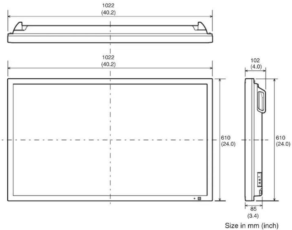
| DIMENSION (W x H x D) | 1022 x 610 x 85 mm ( 402.4" x 240.2" x 33.5") (not including handles) |
| WEIGHT (NET) | 29.8 kg ( 65.7 lbs ) (Plasma Monitor only) |
| Regulations | FCC CLASS-A, UL (PDP-42WV1A/PDP-42WV2A), CE (PDP-42WV1/PDP-42WV2) |
| Environmental Considerations | |
| Operating Temperature | 0°C ~ 40°C (32°F ~ 104°F) |
| Humidity | 20 ~ 80% |
| Storage Temperature | -10°C ~ 50°C (14°F ~ 122°F) |
| Humidity | 20 ~ 80 % |
| Accessories | Owner's Manual |
| AC Power Cord | |
| Wired/Wireless Remote Control Transmitter and Batteries | |
| Remote Control Cable | |
●Specifications are subject to change without notice.
- Display panel is manufactured to the highest possible standards. Even though 99.99% of the pixels are effective, a tiny fraction of the pixels (0.01% or less) may be ineffective by the characteristics of the display panel.
MEASUREMENT
OPTIONS
The products listed below are optionally supplied.
When ordering these products, give name and Type No. to sales dealer.
Speaker unit KA-SX-42V (R and L) [BLACK]
KA-SX-42VS (R and L) [SILVER]
Table top stand KA-TD-42V
Tilt mount unit KA-TI-42V
Wall mount unit KA-WA-42V
Contact the sales dealer for other available options.

This symbol on the nameplate means the product is Listed by Underwriters Laboratories Inc. It is designed and manufactured to meet rigid U.L. safety standards against risk of fire, casualty and electrical hazards.
CONFIGURATIONS OF RS232C TERMINALS
RS232C TERMINAL
Terminal : HDB9-PIN
Connect the serial port of computer to this terminal with Serial Cross Cable (not supplied).
Pin Configuration
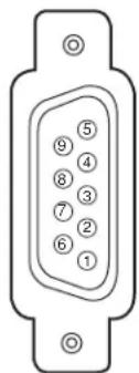
| 1 | No Connect | 6 | No Connect |
| 2 | R x D | 7 | No Connect |
| 3 | T x D | 8 | No Connect |
| 4 | No Connect | 9 | No Connect |
| 5 | Ground | ||
INTERFACE
| Protocol | RS-232C |
| Baud rate | 9600 bps |
| Data length | 8 bits |
| Parity | - |
| Stop bit | 2 bits |
| Flow control | - |
COMMAND (ASCII)
| OPERATION | COMMAND |
| POWER ON-OFF | C03 |
| POWER ON | C00 |
| POWER OFF | C01 |
| VOLUME UP | C09 |
| VOLUME DOWN | C0A |
| MUTE | C0B |
| WIDE (Wide mode select) | C10 |
| Wide mode "Normal" | C0F |
| Wide mode "Zoom" | C27 |
| Wide mode "Full" | C29 |
| PICTURE | C30 |
| Screen Saver "Rotation-On" | C46 |
| Screen Saver "Rotation-Off" | C47 |
| Screen Saver "White pattern-On" | C5F |
| Screen Saver "White pattern-Off" | C60 |
EXAMPLE : POWER ON (C00)
| FUNCTION CODE / END CODE | |
| HEX | 43h 30h 30h 0Dh 0Ah |
| ASCII | 'C' '0' '0' [CR] [LF] |
CONFIGURATIONS OF PC TERMINALS
PC IN (D-SUB) TERMINAL
Terminal : HDB15-PIN
Connect the display output terminal of computer to this terminal with VGA Cable (not supplied). When connecting the Macintosh computer, the MAC Adapter (not supplied) is required.
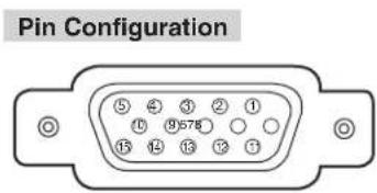
| 1 | Red Input | 9 | No Connect |
| 2 | Green Input | 10 | Ground (Vert.sync.) |
| 3 | Blue Input | 11 | Sense 0 |
| 4 | Sense 2 | 12 | Sense 1 |
| 5 | Ground (Horiz.sync.) | 13 | Horiz. sync. |
| 6 | Ground (Red) | 14 | Vert. sync. |
| 7 | Ground (Green) | 15 | Reserved |
| 8 | Ground (Blue) | ||
MAC ADAPTER (NOT SUPPLIED)
Set Slide Switches as shown in the table below depending on RESOLUTION MODE that you want to use before you turn-on Plasma Monitor and computer.
Slide Switches (1 \~ 6)
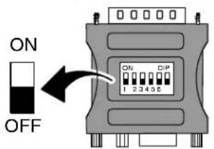
| 1 2 | 3 4 5 6 | |||||
| 13" MODE (640 x 480) | ON | ON | OFF | OFF | OFF | OFF |
| 16" MODE (832 x 624) | OFF | ON | OFF | ON | OFF | OFF |
| 19" MODE (1024 x 768) | OFF | ON | ON | OFF | OFF | OFF |