
PID-42AE1 - Monitor SANYO - Free user manual and instructions
Find the device manual for free PID-42AE1 SANYO in PDF.


| Product Type | Plasma Display Monitor |
| Brand | Sanyo |
| Model | PID-42AE1 |
| Display Size (Diagonal) | 42 inches |
| Aspect Ratio | 16:9 |
| Resolution | 1920 x 1080 (Full HD) |
| Brightness | 1000 cd/m² (typical) |
| Contrast Ratio | 3000:1 |
| Viewing Angle | 178° horizontal / 178° vertical |
| Input Connectors | VGA, DVI-D, HDMI, Component, Composite, S-Video |
| Power Consumption | Approx. 280 W (max) |
| Standby Power | < 1 W |
| Dimensions (W x H x D) with Stand | 1020 x 650 x 250 mm |
| Weight (with Stand) | 15 kg |
| VESA Mount Pattern | 400 x 400 mm |
| Speakers | Built-in stereo (10 W + 10 W) |
| Remote Control | Included (IR) |
| On-Screen Display Languages | English, French, Spanish, German, Italian |
| Safety Features | Ventilation slots, no water exposure, use grounded outlet |
| Cleaning Instructions | Use a soft dry cloth; do not use liquid or abrasive cleaners |
| Spare Parts Availability | Contact Sanyo or authorized service centers |
Frequently Asked Questions - PID-42AE1 SANYO
User questions about PID-42AE1 SANYO
0 question about this device. Answer the ones you know or ask your own.
Ask a new question about this device
Download the instructions for your Monitor in PDF format for free! Find your manual PID-42AE1 - SANYO and take your electronic device back in hand. On this page are published all the documents necessary for the use of your device. PID-42AE1 by SANYO.
USER MANUAL PID-42AE1 SANYO
natural_image
Line drawing of a rectangular electronic device with a blank screen and labeled ports (no text or symbols on the device itself)GB
TABLE OF CONTENTS
GB
TABLE OF CONTENTS 2
SAFETY PRECAUTIONS.... 3
Installation and Use.... 3
SERVICING....4
Servicing 4
Federal Communications Commission Notice ..... 5
AC Power Cord Requirement 6
End-User License 6
Installation Notice 7
INSTALLATION 8
Step: 1 Mains Connection .... 8
Step: 2 Connections 8
Remote control 9
Remote control battery installation 9
Controls and Menus ....10
Menu Operation....10
Picture menu....10
Selection of picture size 14
PIP/POP Operation....15
Teletext Operation....16
SPECIFICATIONS/HELPFUL HINTS.....17
Specification 17
Helpful hints....17
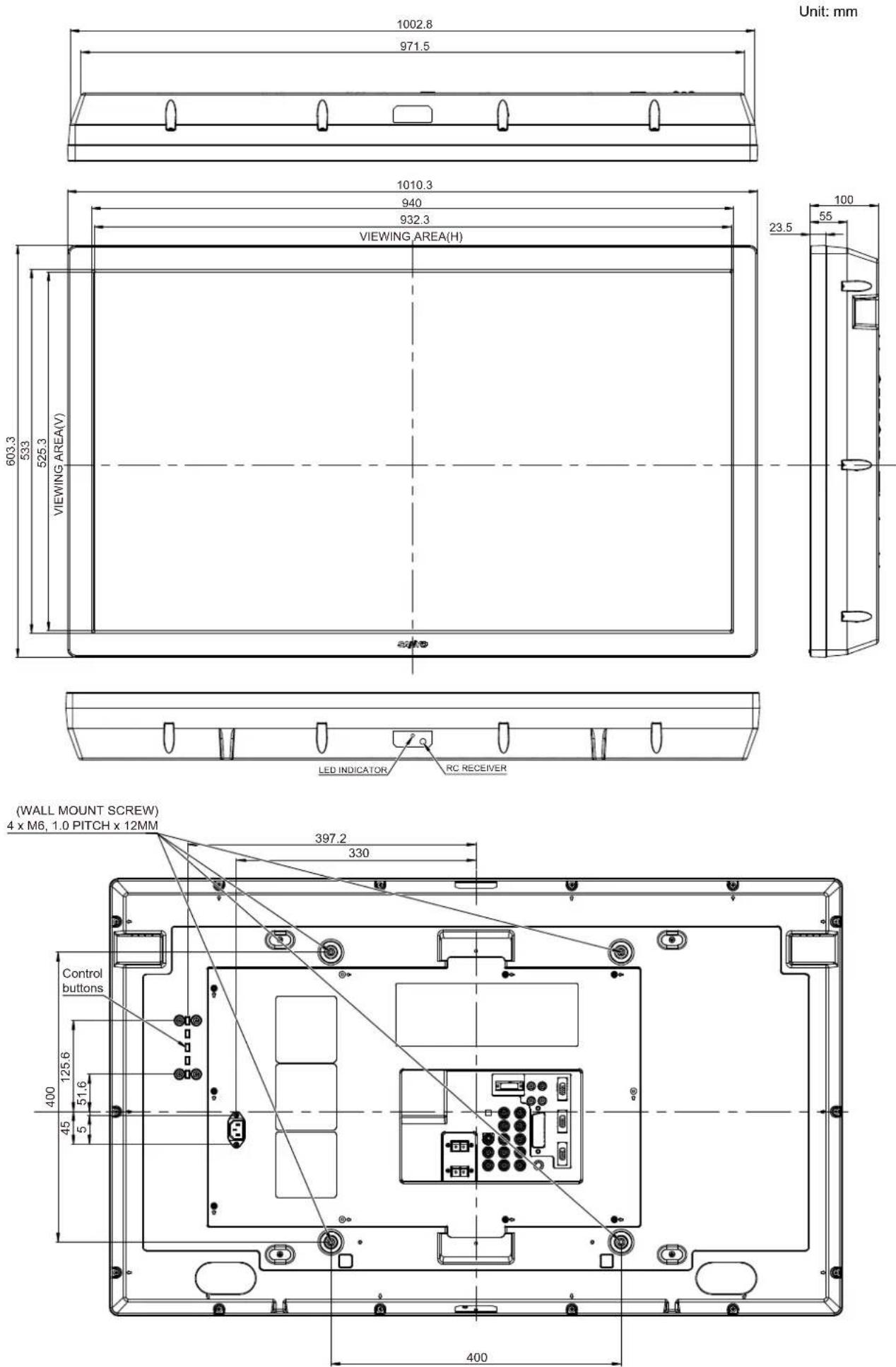
DIMENSIONS.... 18
PC/DVI-D/COMPONENT SIGNAL SUPPORT TIMING LIST.... 19
RS232C COMMAND TABLES 20
Standard monitor (PID-42AE1)
- EXTENSIVE INPUT & OUTPUT TERMINALS (for all products)
This monitor set has various input and output terminals including component (Y,Pb,Pr) or RGBHV input and output with 5-BNC, composite video input and output with BNC, and RS-232 control port (serial D-Sub 9) input and output which offer the daisy chain connection. There are computer inputs (a D-Sub 15 RGB terminal) and DVI-D input with HDCP for High definition signals. There are also jacks for external speakers.
Daylight readable monitor (PID-42AS1)
In addition to Standard monitor, it has adaptive brightness in accordance with prevailing light conditions.
Trademarks
Each name of corporations or products in this book is either a registered trademark or a trademark of its respective corporation.
CAUTION: Please read and retain for your safety. This unit has been designed and manufactured to assure your personal safety, but improper use can result in potential electric shock or fire hazards. In order not to defeat the safeguards incorporated in this monitor observe the following basic rules for its installation, use and servicing.
Installation and Use
natural_image
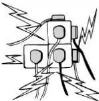
Pure electrical circuit lines without any symbolsDo not allow anything to rest on the power cord. Do not locate this LCD monitor where the cord will be damaged by people walking on it.
Do not overload wall outlets and extension cords as this can result in fire or electric shock. A suitable socket outlet must be provided near to the monitor and shall be easily accessible.
Do not place this LCD monitor near any heat
sources such as radiators, heaters, stoves and other heat-generating products (including amplifiers).
Do not place your LCD monitor on an unstable stand, shelf or table. Serious injury to an individual, and damage to the LCD monitor may result if it should fall. Your sales person can recommend an approved wall mounting kit. A special wall mounting kit is available for this model.
This LCD monitor should be operated only from the type of power source indicated on the monitor or as indicated in the Operating Instructions. If you are not sure of the type of power supply, consult your sales person or your local power company.
For added protection it is strongly recommended that this LCD monitor has its mains supplied via an approved earth fault protection device.
WARNING: To prevent injury the LCD monitor must be securely attached to the wall in accordance with the manufacturers installation instructions.
IMPORTANT:
This product must be earthed.
This unit is not disconnected from the mains unless the mains lead is unplugged. The installer must make sure that the mains plug is easily accessible.
Do not use immediately after moving the LCD monitor from a low temperature to a high temperature environment, as this causes condensation, which may result in fire, electric shock, or other hazards. Before cleaning, unplug the monitor from the wall socket.
Do not mount near an open flame source. Open flames must never be used near this LCD monitor.
This LCD monitor should not be built in or enclosed in any way, heat build up will reduce the life of the monitor.
This LCD monitor should have a minimum distance of 5cm away from the wall and the monitor should have 10cm distance around the top and sides.
Always mount using recommended and substantial fixtures and fittings.
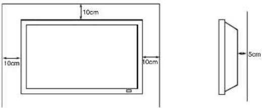
Do not cover the ventilation slot on the LCD monitor. Heat build-up can reduce the service life of your LCD monitor, and can also be dangerous.
Do not apply liquid cleaners or aerosol cleaners directly onto the LCD monitor. Use a damp cloth for cleaning.
ADDITIONAL FOR NORTH AMERICA AND CANADA:
This monitor must NOT be permanently mounted to the building structure. It must be mounted in such a way that it can be removed using basic tools.
The power supply cord must NOT be attached to the building surface. The power supply cord must NOT be routed through walls, ceiling, floors, or other similar openings in the building structure.
The power supply cord MUST be positioned so as to prevent physical damage.
Important: (UK only)
THIS PRODUCT MUST BE EARTHED.
This equipment is fitted with an approved mains lead and an approved non rewireable UK mains plug. To change a fuse in this type of plug proceed as follows:
- Remove the fuse cover and fuse.
- Fit a new fuse which should be a BS1362 13 Amp A.S.T.A. or BSI approved type.
- Ensure that the fuse cover is correctly refitted.
If the fuse cover is lost or damaged the plug must NOT be used but replaced with a serviceable plug.
If the fitted plug is not suitable for your socket outlets, it should be cut off and an appropriate plug fitted in its place. If the mains plug contains a fuse, this should have a rating of 13 Amp, ensure the fuse cover is correctly fitted. If a plug without a fuse is used, the fuse at the distribution board should not be greater than 13 Amp.
Note: The severed plug must be destroyed to avoid a possible shock hazard should it be inserted into a 13 Amp socket elsewhere.
The wires in this mains lead are coloured in accordance with the following code:
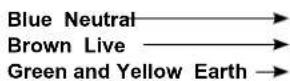
- The Blue wire must be connected to the terminal which is marked with the letter "N" or coloured BLACK.
- The Brown wire must be connected to the terminal with the letter "L" or coloured RED.
- The Green and Yellow wire must be connected to the terminal which is marked with the letter "E" or coloured GREEN or GREEN and YELLOW.
Before replacing the plug cover, make certain that the cord grip is clamped over the sheath of the lead - not simply over the wires.
Do not attempt to bypass the safety purpose of the grounding type plug.
THIS UNIT IS NOT DISCONNECTED FROM THE MAINS UNLESS THE MAINS LEAD IS UNPLUGGED.
THE INSTALLER MUST MAKE SURE THE MAINS LEAD IS EASILY ACCESSIBLE.
Servicing
Your monitor is fully transistorised and does not contain any user serviceable components.
You must not remove the rear cover of the monitor by yourself. The apparatus is working with high voltages and could damage objects or even endanger people. Leave all required repair and service jobs to an authorised service technician. He will exclusively use such spare parts that are complying with the same safety standards as applicable to the original parts. The use of original spare parts can prevent fire, shock and other hazards.
Unplug the LCD monitor from the wall outlet and refer servicing to qualified service personnel under the following conditions:
■ If the power cord or plug is damaged.
■ If liquid has been spilt in to the LCD monitor.
■ If the LCD monitor has been dropped or the cabinet has been damaged.
■ If the LCD monitor exhibits a distinct change in performance.
■ If the LCD monitor does not operate normally by following the operating instructions.
■ If the LCD monitor has been exposed to rain or water.

Adjust only those controls that are covered in the operating instructions as improper adjustment of other controls may result in damage. This will often require extensive work by a qualified technician to restore the monitor to normal operation.
Important recycling information.

natural_image
Simple line drawing of a trash bin with crossed lines indicating no waste or restriction (no text or symbols)Your SANYO product is designed and manufactured with high quality materials and components which can be recycled and reused.
This symbol means that electrical and electronic equipment, at their end-of-life, should be disposed of separately.
In the European Union there are separate collection systems for used electrical and electronic products.
Please help us to conserve the environment we live in!
Note: This symbol mark and recycle system are applied only to EU countries are not applied to other countries of the world.
Federal Communications Commission Notice
This equipment has been tested and found to comply with the limits for a Class A digital device, pursuant to Part 15 of FCC Rules. These limits are designed to provide reasonable protection against harmful interference when the equipment is operated in a commercial environment. This equipment generates, uses, and can radiate radio frequency energy and, if not installed and used in accordance with the instruction manual, may cause harmful interference to radio communications. Operation of this equipment in a residential area is likely to cause harmful interference in which case the user will be required to correct the interference at his own expense.
Do not make any changes or modifications to the equipment unless otherwise specified in the instructions. If such changes or modifications should be made, you could be required to stop operation of the equipment.
Canadian Radio Interference Regulations
This Class A digital apparatus meets all requirements of the Canadian ICES-003.
WARNING
This is a Class A product. In a domestic environment this product may cause radio interference in which case the user may be required to take adequate measures.
AC Power Cord Requirement
The AC Power Cord supplied with this LCD monitor meets the requirement for use in the country in which you purchase it.
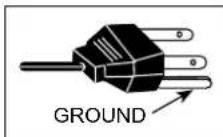
AC Power Cord for the United States and Canada:
AC Power Cord used in the United States and Canada is listed by the Underwriters Laboratories (UL) and certified by the Canadian Standard Association (CSA).
AC Power Cord has a grounding-type AC line plug. This is a safety feature to make sure that the plug will fit into the power outlet. Do not try to defeat this safety feature. Should you be unable to insert the plug into the outlet, contact your electrician.
THE SOCKET-OUTLET SHOULD BE INSTALLED NEAR THE EQUIPMENT AND EASILY ACCESSIBLE
End-User License
The product (meaning the equipment or appliance to which this documentation relates) incorporates Software (the software applications, utilities and modules embedded within the Product) which is owned by Sanyo or its licensors. Before using the product, please read the End-User License Conditions detailed below. If you do not agree to the terms and conditions of the End-User License, Please do not proceed to use the Product-repack the Product unused and return it to your supplier together with proof of purchase for a full refund. By using the product, you agree to be bound by the terms and conditions of the End-User License.
License Grant, Conditions and restrictions
- Sanyo grants you a non-exclusive, world-wide (subject to export controls), non-transferable (except as permitted by 2 below), royalty-free license to use the Software upon and with the Product.
- You may not transfer any of your license rights in the Software without the prior written consent of SANYO and if consent is provided then the Software shall only be transferred in conjunction with the transfer of the Product AND provided that the transferee has read and agreed to accept the terms and conditions of this license.
- You must ensure that the copyright, trademark and other protective notices contained in the Software are maintained and not altered or removed.
- The Software provided hereunder is copyrighted and licensed (not sold). SANYO especially does not transfer title or and ownership rights in the Software to you. The Software provided hereunder may contain or be derived from portions of materials provided to SANYO under license by a third party supplier.
-
Except as expressly permitted by statute you may not;
-
use the Software in conjunction with any other computer hardware other than the product;
• copy all or part of the Software; - incorporate all (or any of) the Software into other programs developed by (or on behalf of) you and/or used by you;
- reverse-engineer, decompile or disassemble the Software;
- make the Software (or any part of it) available, or permit its redistribution, for use with any computer hardware other than the Product; or rent, lease, gift, loan, sell, distribute or transfer possession of the whole or any part of the Software.
Termination
This license is effective until terminated. This license will terminate automatically without notice if you fail to comply with any of its provisions.
Disclaimer
- The Software is (to the extent permitted by law) supplied "as is" and SANYO and its suppliers expressly exclude all warranties, express or implied, including (but not limited to) warranties of satisfactory quality, fitness for purpose and non-infringement (save to the extent that the same are not capable of exclusion at law).
- In no circumstances will SANYO be liable for any direct, indirect, consequential, or incidental damage (including loss of profits, business interruption, loss of data or the cost of procurement of substitute goods, technology or services) arising out of the use or the inability to use the Software (save to the extent that such liability is not capable of exclusion at law).
General
- This End-User License will be governed by laws of England and the User may only bring claims in the English Courts and SANYO shall be entitled to bring a claim in the courts of any jurisdiction.
- This End-User License is governed by the laws of the State of California. The End-User and Sanyo agree that any action to enforce or interpret the terms of this End-User License shall be brought only in the appropriate state or federal court located in Los Angeles County, California. The End-User and Sanyo hereby submit to the exclusive jurisdiction and venue of such court.
- The above terms and conditions supersede any prior agreement, oral or written, between you and SANYO relating to the Software.
Installation Notice
- The LCD monitor can be installed by the following two ways:
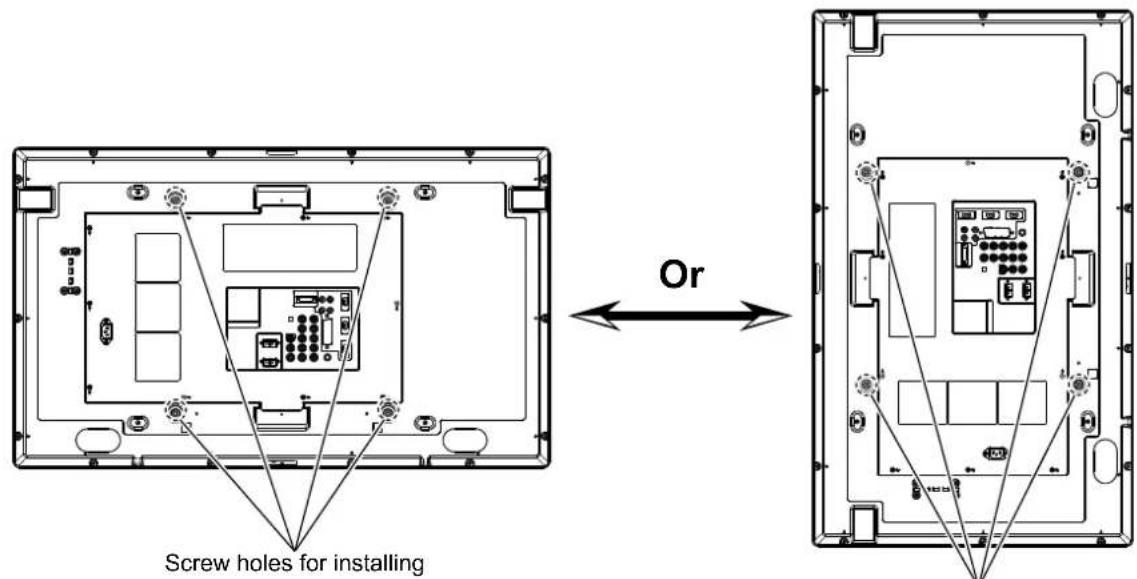
Screws:
Spec : M6 X 12MM (metric)
Material : Stainless Steel
Note:
Don't install the TV set reversed as shown below :
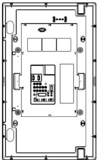
natural_image
Top-down schematic of a device layout with labeled ports and connectors (no readable text or symbols)NG
- The product should be mounted to wall only as recommended by the manufacturer.
-
The installation of the bracket must be done by a qualified professional.
-
Installing the bracket by unqualified personnel may result in injury.
●Always use the mounting device specified by a qualified professional.
Note:
For use only with UL Listed Wall Mount Bracket.
Step: 1 Mains Connection
■ Connect the display unit to VGA, BNC and Scart connector as required.
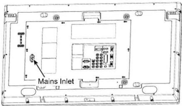
- Connect the in-line power connector to the Mains Inlet as shown above.
- Connect the power cord of the LCD monitor to a suitable wall outlet.
As this product does not have a mains On/Off switch, please ensure your mains plug is easily accessible.
The LCD monitor is prepared for a mains voltage AC100 \~ 240V, 50Hz/60Hz. To completely switch off the mains, or when the display unit is not to be used for an extended period of time, it is advisable to disconnect the power cord from the power outlet.
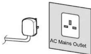
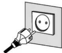
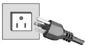
natural_image
Electrical outlet with two 2-pin socket connected to a power plug (no text or symbols visible)Please use the correct mains lead supplied with the set for your area.
3. Warning: To prevent injury, the unit must be securely attached to the wall in accordance with the installation instructions.

WARNING! High voltages are used in the operation of this set. Refer service to qualified service personnel.
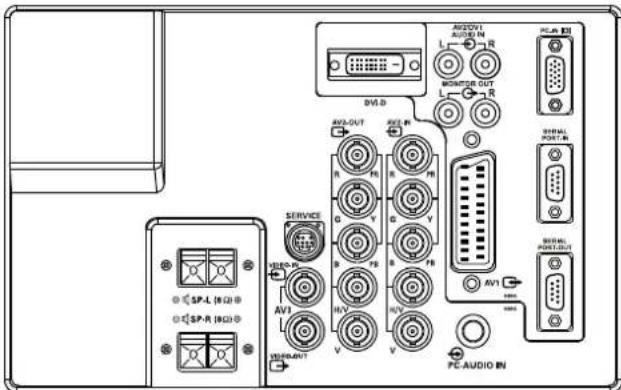
Step: 2 Connections
■ INPUT selection
To switch either AV1, RGB, AV2, AV3, PC, DVI or Network by pressing the INPUT button on your remote control repeatedly.
- AV1
SCART connection/CVBS/RGB/S-VIDEO.
- RGB
TTL input (5V RGB signals) into SCART terminal.
- Y, Pb, Pr/RGBHV connection (AV2)
Choose Y, Pb, Pr or RGB H/V connection by selecting AV2 Setting in Set up menu (see page 12). You can connect your DVD player to the Y, Pb, Pr terminals instead of using a scart lead. This can support high definition in analogue component form. RGB H/V can be used as a PC input via the BNC terminals. Both options support a large range of resolutions (page 19). AV2-OUT can be used to output the incoming AV2 signal to the other monitor.
- AV3
Composite (CVBS) signal input.
AV3-OUT can be used to output the incoming AV3 signal to the other monitor.
- DVI-D (Digital Video Interface)
DVI-D supports a large range of resolutions as shown on page 19.
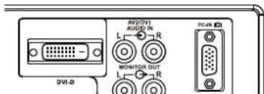
- PC connection
PC input (PC-IN D-SUB). This input supports a large range of resolutions as shown page 19. Audio can be connected via the 3.5mm PC-AUDIO IN.
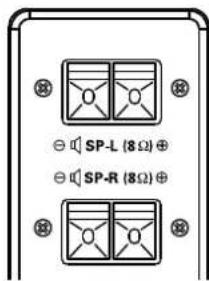
- External Speaker
Output the audio signal from AV1, AV2, AV3, PC and DVI. The speaker impedance is 8 ohms.
- AV2 / DVI AUDIO IN
Connect the audio output (stereo) from a computer or video equipment connected AV2 or DVI.
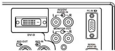
- Monitor Audio OUT
This terminals output fixed level from AUDIO IN.
- RS232C IN/OUT
When the monitor is controlled by a computer, connect to this jack with serial control cable.
You can connect to another monitor with RS232C OUT.
When you connect PC with RS232C, select "ON" at Network standby in Installation mode.
If it is selected "OFF", RS232C terminals do not functional. Also select push button to "SERIAL POART".
Remote control
Input
To switch input source from AV1, RGB, AV2, AV3, PC, DVI or Network mode.
Wide
To select the screen mode Full, Full All, Zoom 16:9, Title in 16:9, Zoom 14:9, Title in 14:9, Normal or Natural wide. Refer to page 14.
Menu
To enter and exit the main menu, and sub menu.
Level Up/Down
To adjust the sound volume level or enter sub menus.
F/OK
To confirm the initial setting in the menu.
Picture mode selector
Press the button repeatedly to select the following picture mode.
Personal - Personal preference mode.
Standard - Normal viewing mode.
Dynamic - Suitable for brightly lit rooms.
Soft - Low contrast setting
Eco - Suitable for dimly lit rooms and gives a cinema-like effect.
Freeze
To switch picture still on or off.
Green
Press this button for more than 5 seconds, installation mode will appear.
Standby
To switch the monitor on and off. Also see page 10.
Recall
To display input selection information and the Time set. You can also select colour systems in AV1/AV3 mode as follows: AUTO → PAL → SECAM → NTSC → NTSC4.43 → PAL M → PAL N.
Auto PC
It can also be automatically adjusted in PC mode by pressing this button for twice.
Back
Used to return to the previous menu.
Up and Down
To select the next or previous item.
Sound Mute
To mute the sound from the speakers. The sound changes as follows: Normal volume Mute.
Bass Expander
To get an emphasised bass sound ON or OFF.
TXT/TV
To select Teletext mode.
Main/Sub Picture Swap
To swap Main and Sub picture.
ON/OFF
To switch OFF → PIP(1) → PIP(2) → POP mode in turn. Refer to page 15.
Remote control battery installation
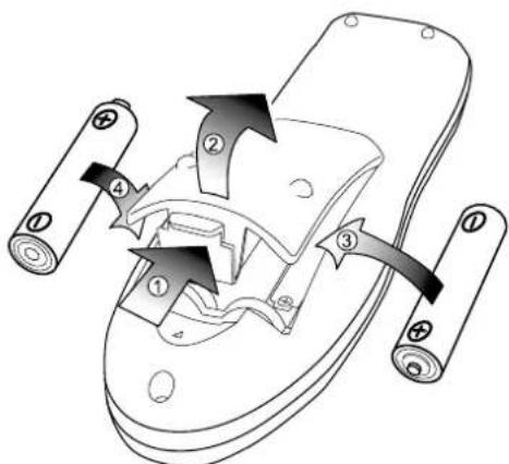
Install two "AA" 1.5 volt batteries so that the "+" and "-" marks on the batteries match the "+" and "-" marks inside the unit into the remote control handset.
FOR EU USERS
The symbol mark and recycling systems described below apply to EU countries and do not apply to countries in other areas of the world. Your SANYO product is designed and manufactured with high quality materials and components which can be recycled and/or reused.
The symbol mark means that electrical and electronic equipment, batteries and accumulators, at their end-of-life, should be disposed of separately from your household waste.
Note:
If a chemical symbol is printed beneath the symbol mark, this chemical symbol means that the battery or accumulator contains a heavy metal at a certain concentration. This will be indicated as follows: Hg: mercury, Cd: cadmium, Pb: lead
In the European Union there are separate collection systems for used electrical and electronic equipment, batteries and accumulators. Please, dispose of them correctly at your local community waste collection/recycling centre.
Please, help us to conserve the environment we live in!
Controls and Menus
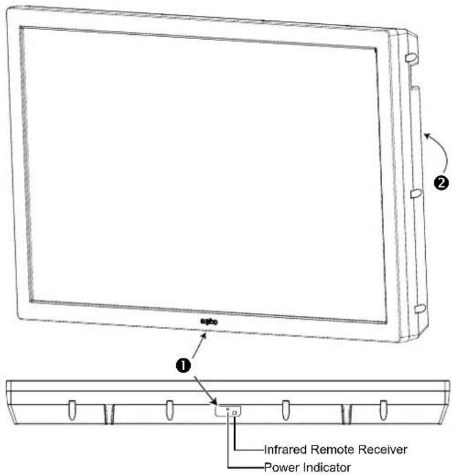
① The LCD display has a Standby light to show there is power.
Switching into/from standby mode
The Standby mode is used for switching the LCD monitor off for short periods of time. In standby mode the monitor is switched off but is still receiving mains power.
- To turn the monitor into standby mode, press the ⏻ button. The blue power indicator illuminates more brightly.
- To turn the monitor ON from standby mode, press the ⏻ button again.
| If you find the power indicator flashing, disconnect power cord from the power outlet and contact our Service desk. | |
| This warning is a sign to let you know that the power protection function of this TV set is now operating. |
② Control buttons (back cover)
Menu button: Used to display or cancel main menu.
Input/▼ button: Switch between AV1, RGB, AV2, AV3, PC, DVI or Network mode. It is also used to provide sub menu selection from the Main Menu.
▲+ or ▲- buttons: provide up and down adjustments.
Button: To switch to standby mode (to switch off completely disconnect the monitor from the power supply).
Menu Operation
Many of your monitors functions are controlled through the menu function, using the remote control.
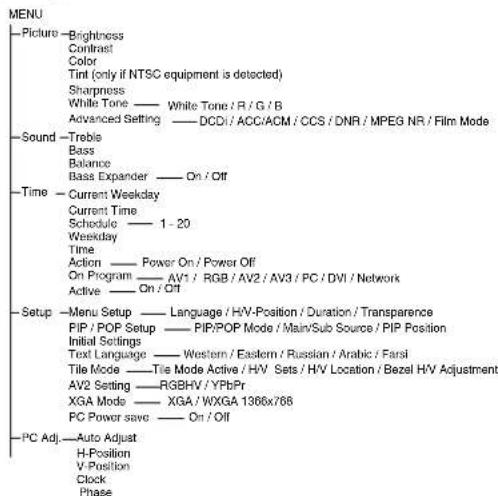
During menu operation the bottom of the on screen display will show which controls can be used for menu navigation.
Press the MENU button to enter the main menu. Whenever main menu is accessed initially, PICTURE will be the default selection.
A sub menu is selected using the P▲ or P▼ button and pressing the ▲+ or ▲- button when the required sub menu is highlighted. When you have finished you can press the BACK button to return to the previous menu, press the MENU button to exit the menu operation.
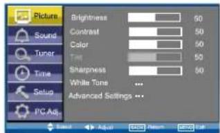
Picture menu
- Press the MENU button. PICTURE will be the default selection. Press the ▲+ or ▲- button to enter. Set the picture settings for your "personal" preference.
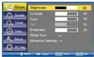
- Use the P▲ or P▼ button to select eg. Brightness and the ▲+ or ▲- button to adjust levels.
■ White Tone
May be used to adjust the color tone of the picture. Use the P▲ or PV▼ button to select White Tone and press the ▲+ or ▲- button to enter the sub menu. You can select Personal, Cool, Standard or Warm settings by using the ▲+ or ▲- button. To adjust the color tone of the picture by using the P▲ or PV▼ button to select Red(R), Green(G) or Blue(B) and the ▲+ or ▲- button to adjust levels. These settings will be stored in personal mode automatically.
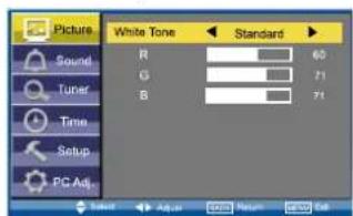
Picture menu
■ Advanced settings
Use the P▲ or PV▼ button to select Advanced settings and press the ▲+ or ▲- button to enter the sub menu as follows.
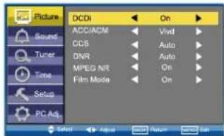
DCDi (Directional Correlational Deinterlacing) is used to process moving angled edge in deinterlacing to get the smoothest and most natural image. Press the ▲+ or ▲- button on the remote control to select On or Off.
ACC/ACM (ACC: Adaptive Contrast and Color; ACM-II: Active Color Management-II) is used to select adaptive Brightness, Contrast and tone control. Press the ▲+ or ▲- button on the remote control to select suitable mode either Vivid, Cinema, Sport or Off.
CCS (Cross Color Separation) is used to remove residual chroma information from luminance signal which is the result of imperfect decoding of composite video. Press the ▲+ or ▲- button on the remote control to select either Auto, Standard or Off.
DNR (Digital Noise Reduction) is available for noise reduction. Press the ▲+ or ▲- button on the remote control to select either Auto, Low, Mid, High or Off.
MPEG NR (MPEG Noise Reduction): Removes unwanted ringing and block noise from images that have undergone MPEG or JPEG compression and decompression. Press the ▲+ or ▲- button on the remote control to select On or Off.
Film Mode (Inverse 3:2 pulldown): Film vs. Video-Detect film. Performed on material which underwent technologic conversion to video. Press the + or - button on the remote control to select On or Off.
Sound menu
Press the MENU button and select Sound using the 5 or 6 buttons, press the 1 or 2 button to enter.
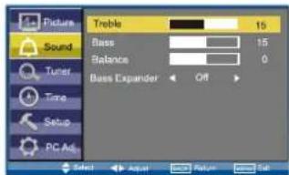
Select and adjust to obtain the best sound settings for your environment using the P▲ or P▼ button to select Treble, Bass or Balance and the ▲+ or ▲- button to adjust levels.
Bass Expander can also be selected using the P▲ or P▼ button and pressing the ▲+ or ▲- button to select On or Off. These settings automatically store when you exit the menu.
Press the BACK button to return to the previous menu. Press the MENU button to exit menu operation.
Time menu
Press the MENU button and select Time using the P▲ or P▼ buttons, press the ▲+ or ▲- button to enter. Press the BACK button to return to the previous menu. Press the MENU button to exit menu operation.
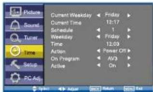
■ Current Weekday
Use to set current weekday using the ▲+ or ▲- button.
■ Current Time
Use to set the current time using the Numeric buttons.
Other items in Time Menu should not be selected until Current Time has been set.
Schedule
Use to set up to 20 separate time schedules for "Power On" or "Power Off", select 1 \~ 20 using the ▲+ or ▲- button.
■ Weekday
Use to set the schedule for "Power On" or "Power Off" of any weekday from Sunday through to Saturday or Everyday using the ▲+ or ▲- button.
Time
Use to set the schedule for "Power On" or "Power Off" of any time using the Numeric buttons.
■ Action
Use to set the schedule for "Power On" or "Power Off" active using the ▲+ or ▲- button.
You can set Power On timer in Time menu selecting "ON" in "On Timer Function" in Installation Mode. If it is selected "OFF", Power On display in Time menu does not functional.
■ On Program
Use to select AV1, RGB, AV2, AV3, PC, DVI or Network for the schedule of "Power On" using the ▲+ or ▲- button.
■ Active
Use to select ON or OFF using the ▲+ or ▲- button. When set "OFF" the above items "Schedule", "Weekday", "Time", "Action" or "ON Program" will be inactive.
Use NUMERIC buttons [0 \~ 9] to set On Time. (Action "Power On" - 00:00 \~ 23:59)
Once On Time has been set, when the set time is reached, the monitor will leave the stand-by status and enter to the source automatically.
After On Time has been set, you can go on watching other programs. When the set time is reached, the monitor will automatically switch to the preset program.
On Program can only be selected whenAction (Power On) has been set.
Action (Power Off) can be set to turn the monitor into standby at a selected time
Once On Program has been set, when the set time is reached, the monitor will enter to the preset source automatically.
Use the ▲+ or ▲- button to select On program, AV1, RGB, AV2, AV3, PC, DVI or Network.
Setup menu
Press the MENU button and select Setup using the P▲ or P▼ buttons, press the ▲+ or ▲- button to enter. Press the BACK button to return to the previous menu. Press the MENU button to exit.
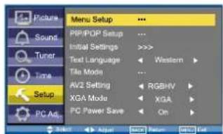
■ Menu Setup
Whenever Setup menu is accessed initially, Menu Setup will be the default selection. Press the ▲+ or ▲- button to enter the sub menu.
GB GMENU OPERATION

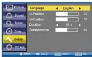
Language is used to select the preferred language. Use the ▲+ or ▲- button to select English, French, German, Italian, Spanish or Dutch.
H-Position changes the OSD position horizontally by using the ▲+ or ▲- button.
V-Position changes the OSD position vertically by using the ▲+ or ▲- button.
Duration is used to set the display time of the MENU by using the ▲+ or ▲- button. (5 \~ 120 seconds)
Transparence is used to adjust transparence of menu display. Use the ▲+ or ▲- button to adjust levels.
■ PIP/POP Setup
Use the P▲ or P▼ button to select PIP/POP Setup and press the ▲+ or ▲- button to enter the sub menu.
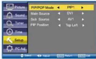
PIP/POP Mode: Using the ▲+ or ▲- button select the most suitable mode PIP1, PIP2, POP or Off. (Please refer to page 15.)
When Mode is set to Off, Sub Source and PIP Position will not work.
Main Source is used to select input source (AV1, RGB, AV2, AV3, PC, DVI or Network) for main picture by using the ▲+ or ▲- button.
Sub Source is used to select input source (AV1, AV2, AV3, PC or DVI) for sub picture by using the ▲+ or ▲- button.
For a combination of main picture and sub picture: only DVI or Network input can assemble with other input source. For example, if main source is selected as AV1 input, then the sub source must be DVI or Network input.
PIP Position: Using the ▲+ or ▲- button it can be selected Top Left, Top Right, Bottom Right or Bottom Left.
■ Initial Settings
This function returns all setting values except for Installation Mode.
■ Text Language
Use the P▲ or P▼ button to select Text Language and press the ▲+ or ▲- button to select Western, Eastern, Russian, Arabic or Farsi.
■ Tile Mode
This function allows you to split an image to suit your monitor grid format to create a video wall.
Use the P▲ or PV▼ button to select Tile Mode and press the ▲+ or ▲- button to enter the sub menu as follows.
Tile Mode Active can be set On or Off using the ▲+ or ▲- button.
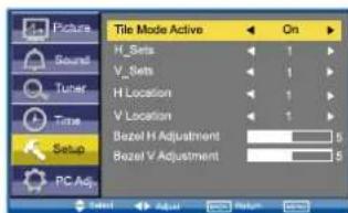
H_Sets is used to divide the horizontal picture into more than one part, but the most is 5 parts (5 monitors).
V_Sets is used to divide the vertical picture into more than one part, and the most is also 5 parts (5 monitors). Using the ▲+ or ▲- button to set.
H Location is used to select one part of the horizontal picture to display on the current LCD Monitor using the ▲+ or ▲- button.
V Location is used to select one part of the vertical picture to display on the current LCD Monitor using the ▲+ or ▲- button.
Bezel H Adjustment is used to align the image horizontally with respect to the other monitors in the video wall to accommodate the bezel width using the ▲+ or ▲- button. (0 \~ 10)
Bezel V Adjustment is used to align the image vertically with respect to the other monitors in the video wall to accommodate the bezel width using the ▲+ or ▲- button. (0 \~ 10)
■ AV2 Setting
Use the P▲ or PV▼ button to select AV2 Setting and press the ▲+ or ▲- button to select YPbPr or RGBHV.
Connect your PC to either PC-IN or RGBHV on the rear of the set. Once connected select PC mode or AV2 (RGBHV, see page 8 for AV2 input settings) via the INPUT button on your remote control. The set will become a monitor for the PC.
XGA Mode
Use the P▲ or P▼ button to select XGA Mode and press the ▲+ or ▲- button to select XGA or WXGA 1366 x 768.
■ PC Power Save
The monitor set automatically turns off with no PC input signal and wakes up with signal while PC Power Save is active.
Use the P▲ or P▼ button to select PC Power Save and press the ▲+ or ▲- button to select ON or OFF.
PC Adj. menu
Press the MENU button and select PC Adj. using the P▲ or P▼ buttons, press the ▲+ or ▲- button to enter. Press the BACK button to return to the previous menu. Press the MENU button to exit menu operation.
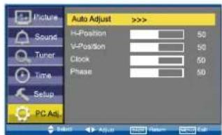
Auto Adjust is used to automatically detect incoming signal, and adjust itself to optimize its performance by using the ▲+ or ▲-button. If the image is not displayed properly, a manual adjustment is required (Refer to following adjustments).
H-Position is used to move the horizontal picture position by using the ▲+ or ▲- button.
V-Position is used to move the vertical picture position by using the ▲+ or ▲- button.
Clock is used to eliminate flicker from the image by using the ▲+ or ▲- button.
Phase is used to eliminate disorder from the image by using the ▲+ or ▲- button.
Installation Mode
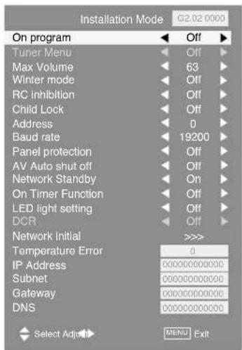
This LCD monitor allows you to set up the following:
SETTING PROCEDURE
- Press and hold the GREEN button on the remote control for 5 seconds. (Installation Mode will appear)
- Use the P▲ or PV▼ button to highlight each option, use the ▲+ or ▲- button to adjust each option. Press the MENU button to exit the mode.
■ On Program
Select ON program using the P▲ or P▼ button, select the start up position using the ▲+ or ▲- buttons. (Off/AV1/RGB/AV2/AV3/PC/DVI or Network)
Max Volume
Select Max volume using the P▲ or PV▼ button, use the ▲+ or ▲-buttons to set the maximum volume required.
Winter mode
This Function can be activated when the LCD monitor is used during cold temperature conditions, approximately 38^ F/4°C or below to maintain picture performance.
Using the P▲ or P▼ button select winter mode, once highlighted you can select ON or OFF by pressing the ▲+ or ▲- button. IMPORTANT: The AC cord should not be disconnected during the operation of Winter mode function.
When in winter mode, power consumption is higher than normal standby consumption. This is entirely due to the operation of heating circuitry. We strongly recommend to turn off Winter mode when the ambient temperature is above 38^ F/4°C.
■ RC inhibition
You can prevent unwanted remote control operation by selecting RC Inhibition.
Select using the P▲ or P▼ button. Press the ▲+ or ▲- button to select On or Off.
To re-instate RC operation press and hold the green button on the remote control and select RC inhibition OFF.
■ Child Lock
You can prevent unwanted operation of the LCD monitor via the buttons on the rear of the monitor.
Select using the P▲ or P▼ button. Press the ▲+ button to select On or OFF. The "Child Lock" OSD will appear if buttons are pressed when child lock is On.
Standby operates normally when childlock is set "On".
Address
Set the address for the LCD monitor (0 \~ 999).
- Setting the monitor address in RS232 mode
Each monitor can have a specific Address, which helps command that monitor individually and will not effect to other monitors connected to a controlling PC Address format command. The addressing format command is used for operating multiple monitor sets from a single PC via the RS232C command line.
■ Baud rate
Select Baud rate using the P▲ or P▼ button. To set transmission speed RS232 or LD-NET communication for 19200 or 9600 Baud rate by pressing the ▲+ or ▲- button.
■ Panel protection
To prevent image sticking which may occur showing still picture for a long time, select "Panel Protect" using the P▲ or P▼ button, once highlighted you can select ON or OFF by pressing the ▲+ or ▲-button.
■ AV Auto shut off
With no picture input signal to AV1, RGB, AV2(YPbPr), AV3, DVI, Network, set turns off automatically. Select "AV Auto Shut Off" using the P▲ or P▼ button, once highlighted you can select On or Off by pressing the ▲+ or ▲- button.
■ Network Standby
You can save power consumption selecting "Off" at Network Standby in Installation mode, RS232C do not functional. To make them functional, select "ON" in this menu.
■ On Timer Function
You can save power consumption selecting "Off" at On Timer function in Installation mode. On Timer in Time menu does not functional. To make them functional, select "ON" in this menu.
■ LED Light setting
Select LED Light setting using the P▲ or P▼ button, once highlighted you can select On or Off by pressing the ▲+ or ▲- button.
DCR
The picture contrast improved while DCR is ON. Select DCR using the P▲ or PV▼ button, once highlighted you can select On or Off by pressing the ▲+ or ▲- button.
■ Network Initial
This function is not used.
■ Temperature Error
The recorded number of abnormal temperature is occurred is indicated here.
■ IP Address/Subnet/Gateway/DNS
This function is not used.
Selection of picture size
Select screen size from FULL, FULL ALL, ZOOM 16:9, TITLE IN 16:9, ZOOM 14:9, TITLE IN 14:9, NORMAL or NATURAL WIDE by pressing the WIDE button repeatedly on the Remote Control.
When in AV2 (RGBHV) or PC mode FULL or NORMAL can be selected.
Note: Full - Set display area 100%
Only in DVI or AV2 (YPbPr) displaying high resolution content FULL and FULL ALL are selectable.
Note: FULL - Set display area 95% FULL ALL - Set display area 100%
All other inputs AV1, AV3, DVI or AV2 (YPbPr) (displaying lower resolutions) can select all picture sizes.
Full/Full All
| 4:3 14:9 16 | 9 Letterbox Video | ||
 |  |  | [HZW] |
| The whole screen is filled stretching the width. | The whole screen is filled stretching the height slightly at the edges. | The whole screen is filled with the correct picture ratio. | The black bars top and bottom are present and the height is compressed. |
■ Zoom 16:9
| 4:3 14:9 16 | 9 Letterbox Video | ||
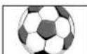 |  | 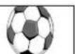 | 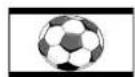 |
| The correct picture width is maintained but the top and bottom are cropped. | Zooms in slightly cropping the top and bottom. | Zooms in slightly cropping the top and bottom. | The black bars top and bottom are smaller and the picture height is compressed slightly. |
■ Title in 16:9
| 4:3 14:9 16 | 9 Letterbox Video | ||
 |  TITEN TITEN |  TIT TIT |  |
| As Zoom (16:9), but bottom is compressed even more to allow subtitles to be seen. | As Zoom (16:9), but bottom is compressed even more to allow subtitles to be seen. | As Zoom (16:9), but bottom is compressed even more to allow subtitles to be seen. | As Zoom (16:9), but bottom is compressed even more to allow subtitles to be seen. |
■ Zoom 14:9
| 4:3 14:9 16 | 9 Letterbox Video | ||
 |  | 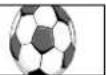 |  |
| The correct picture width is maintained but the top and bottom are cropped. | Zooms in slightly cropping the top and bottom. | Zooms in slightly cropping the top and bottom. | The black bars top and bottom are smaller and the picture height is compressed slightly. |
■ Title In 14:9
| 4:3 14:9 16 | 9 Letterbox Video | ||
 |  |  |  |
| As zoom (14:9), but bottom is compressed even more to allow subtitles to be seen. | As zoom (14:9), but bottom is compressed even more to allow subtitles to be seen. | As zoom (14:9), but bottom is compressed even more to allow subtitles to be seen. | As zoom (14:9), but bottom is compressed even more to allow subtitles to be seen. |
Normal
| 4:3 14:9 16:9 Letterbox Video | |||
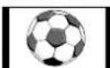 | 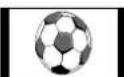 | 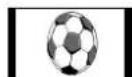 | 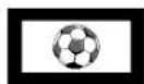 |
| The correct ratio is maintained with black bars on the left and right. | Black bars left and right, picture height is stretched. | Black bars left and right, picture height is stretched. | Black bars left, right, top and bottom. |
Natural Wide
| 4:3 14:9 16 | 9 Letterbox Video | ||
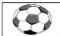 | 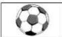 | 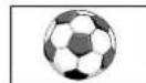 |  |
| Stretches the picture horizontally to fill the screen. The picture is more stretched at the edges. | The height is expanded to fill the whole screen. | The picture fills the screen and is proportionally correct. | The black bars top and bottom remain and the height is compressed to fit the picture area. |
[Non-Text]
PIP/POP Operation
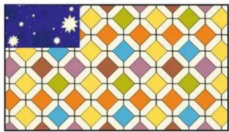
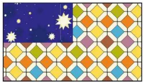
Using this function, you can enjoy a DVI or Network program and an image (AV1, AV2, AV3 or PC input) at the same time. Press the ON/OFF button on the Remote Control repeatedly to select PIP1, PIP2, POP or OFF mode.
During the PIP/POP mode, press the Main/Sub Picture Swap button will switch the location for main and sub picture.
Only the sound on the main picture is heard from the monitor speaker. The sound on the sub-picture cannot be heard.
The details for PIP/POP operation (eg, location for sub picture or input source for any picture, etc.), please refer to page 12.
■ PIP1 mode
natural_image
Colorful geometric tile pattern with a starry night sky on the left (no text or symbols)■ PIP2 mode
natural_image
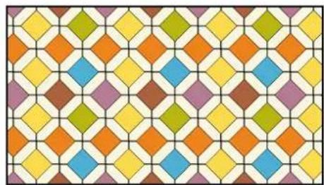
Colorful geometric tile pattern with stars and dots on a blue background (no text or symbols)■ OFF mode
natural_image
Colorful geometric tile pattern with interlocking diamond shapes (no text or symbols)■ POP mode
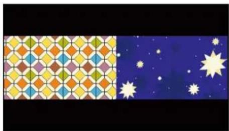
The left picture is main picture, the right picture is sub picture.
natural_image
Colorful geometric pattern on the left and starry night sky on the right (no text or symbols)Teletext Operation
Teletext is only available via external sources.
Teletext mode can be operated by the following buttons on the Remote Control.
Some buttons have dual functions.

TXT/TV
Press TXT/TV button to select teletext. Press again will display:
AV mode: AV/TEXT mode/MIX mode/AV.
Note:
MIX mode: AV (broadcast image) screen and the contents of TEXT (superimposed) are displayed simultaneously.
CANCEL mode: TEXT/MIX MODE is cancelled temporarily and AV image is displayed.
If the signal is removed or disconnected, the monitor will revert to a blue background with "No signal" message on the screen. If the TXT/TV button is pressed during the CANCEL mode, the CAN-CEL mode will be cancelled, and full text will resume.

Text Subcode
Press this button, "110/..." will be displayed (e.g. the current page is 110).
And press the NUMERIC buttons(0 \~ 9) to enter the sub page. For example, to select sub page 4, press NUMERIC buttons 0 - 0 - 0 - 4, and "110/0004" will be displayed.
When finished, press the text subcode button to return to normal operation.

Text Index
Press this button to select one of the teletext index pages in TEXT, MIX or CANCEL mode.

Text Red
Use to select the red topic or page number at the bottom of the text page.

Text Green
Use to select the green topic or page number at the bottom of the text page.

Text Yellow
Use to select the yellow topic or page number at the bottom of the text page.

Text Blue
Use to select the blue topic or page number at the bottom of the text page.

Text Cancel
Press the TEXT CANCEL button in TEXT or MIX mode, the TV picture appears on the screen.
Press this button once again or press TXT/TV button, CANCEL mode will be cancelled.
In CANCEL mode, "CAN" is always displayed on the upper left of the screen.

Text Hold
Press Text Hold button to stop page request and updating.
HOLD ON:
The Hold symbol will appear instead of the page number. Update of TELETEXT is forbidden. It holds on the current TEXT screen display now.
HOLD OFF:
The hold symbol is replaced with the page number.
TELETEXT page data is updated.
The present page is re-requested. (header roll)
Text Hold button will only work whilst in TEXT Mode.

Text Reveal
Press Text Reveal button to reveal hidden items on the text page.
Some pages such as quiz pages have the answers hidden. The button may have to be held to keep the answer on the screen, or press again to remove the answer.
In Reveal OFF, this indication is not given.
Text Reveal button will only work whilst in text mode.

Page Up and Down
To select the next or previous page.

Volume Up/Down
To adjust the sound volume level.

Text Size
Press Text Size button to enlarge the top half of the text page. Press Text Size button again to enlarge the bottom half of the text page.
Press Text Size button again to return to the normal size page. (Normal/top half enlargement/bottom half enlargement/normal)
Note:
During the top half or bottom half enlargement mode, if a page request is performed by [0 9] numeric buttons or the TEXT INDEX button, it will return to normal mode and a page will be requested. If HOLD ON/OFF is performed during the top half enlargement mode, it will hold the top half enlargement mode. (HOLD symbol will display) If HOLD ON/OFF is performed during the bottom half enlargement mode, it will hold the bottom half enlargement mode. (HOLD symbol will NOT display)
Specification
Common specification
Power source: 100 \~ 240V 50Hz/60Hz
Colour system: PAL/NTSC/NTSC4.43/SECAM
AV terminal
AV1: Scart CENELEC Standard
Input: Composite video, RGB (5V RGB with 5V sync to pin 14) and audio-L/R
Output: composite video from AV3 and audio L/R
AV2: BNC
Input: RGB, H and V/Y, Pb, Pr and audio L/R
Output: RGB, H and V/Y, Pb, Pr
AV3: BNC
Input: Composite video
Output: Composite video
Audio Monitor Out: CINCH L/R
Audio Speaker Out: 2 x 6W
DVI
Input: DVI-D GROUP Standard
PC
Input: Mini D-SUB 15 PIN and Audio 3.5mm Jack
Serial Port: RS232C: Input/Output
Helpful hints
- Check if monitor is plugged in.
- Check monitor is not in standby mode.
■ POOR PICTURE
- Adjust BRIGHTNESS/CONTRAST levels (too low).
■ NO COLOUR, PICTURE OK
- Adjust COLOUR control.
- Check lead connections.
- Does the signal input have colour.
■ REMOTE CONTROL DOES NOT WORK
- Check batteries are inserted correctly.
- Check condition of batteries.
- Check to see if remote control inhibit is set ON.
■ PICTURE OK, NO SOUND
- Check external speakers are connected correctly.
- Check lead connections to external equipment.
- Check volume turned down or mute selected.
| Model name Contrast Ratio | Screen (inches/cm) (viewing measured diagonally) | Display Native Resolution | Veiwing angles | Dimension (W x H x D) | Weight (kg) | |
| PID-42AE1 | 1000:1 42"/106.7 cm 1920 x 1080 H: 178°, V: 178° 1010.3 x 603.3 x 100 mm 18 | |||||
| PID-42AS1 | ||||||
- The specifications are subject to change without notice.
- LCD panels are manufactured to the highest possible standards. Even though 99.99% of the pixels are effective, a tiny fraction of the pixels (0.01% or less) may be ineffective by the characteristics of the LCD panels.
■ PC signal support timing
| Resolution | Horizontal Frequency (kHz) | Vertical Frequency (Hz) | Remark |
| 720 x 400 31 | .47 | 70.09 | DOS (VGA) |
| 640 x 480 31 | .43 | 59.88 | VGA VESA 60Hz |
| 640 x 480 37 | .50 | 75.00 | VGA VESA 75Hz |
| 640 x 480 37 | .86 | 72.81 | VGA VESA 72Hz |
| 640 x 480 | 43.27 | 85.00 | VGA VESA 85Hz |
| 640 x 480 | 35.00 | 66.67 | Mac. 13 |
| 640 x 480 | 34.97 | 66.60 | Mac LC 13" |
| 800 x 600 | 35.16 | 56.25 | SVGA VESA 56Hz |
| 800 x 600 | 37.88 | 60.32 | SVGA VESA 60Hz |
| 800 x 600 46 | .875 | 75.00 | SVGA VESA 75Hz |
| 800 x 600 | 34.50 | 55.38 | SVGA |
| 800 x 600 | 38.00 | 60.51 | SVGA |
| 800 x 600 | 53.67 | 85.06 | SVGA VESA 85Hz |
| 832 x 624 49 | .72 | 74.55 | Mac. 16 |
| 1024 x 768 48 | .36 | 60.00 | XGA VESA 60Hz |
| 1024 x 768 56 | .47 | 70.07 | XGA VESA 70Hz |
| 1024 x 768 60 | .02 | 75.03 | XGA VESA 75Hz |
| 1024 x 768 48 | .50 | 60.02 | XGA |
| 1024 x 768 60 | .31 | 74.92 | XGA |
| 1024 x 768 61 | .00 | 75.70 | XGA |
| 1024 x 768 68 | .68 | 85.00 | XGA VESA 85Hz |
| 1024 x 768 60 | .24 | 75.08 | MAC_Normal 19" |
| 1280 x 720 37 | .50.00 | 720p - 50Hz | |
| 1280 x 960 60 | .00 | 60.00 | SXGA VESA 60Hz |
| 1280 x 1024 | 79.976 | 75.025 | SXGA VESA 75Hz |
| 1280 x 1024 | 63.370 | 60.01 | SXGA |
| 1280 x 1024 | 63.34 | 59.98 | SXGA |
| 1280 x 1024 63 | .74 | 60.01 | SXGA |
| 1280 x 1024 63 | .79 | 60.18 | SXGA |
| 1280 x 1024 | 63.90 | 60.00 | SXGA |
| 1280 x 1024 | 81.13 | 76.107 | SXGA |
| 1152 x 900 | 61.20 | 65.20 | SXGA |
| 1152 x 900 | 61.85 | 66.00 | SXGA |
| 1152 x 900 | 71.40 | 75.60 | SXGA |
| 1400 x 1050 | 65.35 | 60.12 | SXGA + |
| 1400 x 1050 65 | .12 | 59.90 | SXGA + |
| 1152 x 870 68 | .68 | 75.06 | MAC_Normal 21" |
| 1280 x 1024 | 80.00 | 75.00 | Mac II |
| 1600 x 1200 | 75.00 | 60.00 | UXGA VESA 60Hz |
| 1366 x 768 48 | .36 | 60.01 | WXGA |
| 1360 x 768 | 47.73 | 60.03 | WXGA |
| 1920 x 1080 | 28.125 | 50.00 | 1080i - 50Hz |
| 1920 x 1080 33 | .75 | 60.00 | 1080i - 60Hz |
The monitor can be automatically adjusted in pc mode when receiving a standard VESA signal. It will be displayed as XGA when the monitor is receiving a XGA or WXGA signal.
■ Component signal support timing
| Resolution | Horizontal Frequency (kHz) | Vertical Frequency (Hz) | Remark |
| 720 x 480 15 | .735 60i SDTV | 480i | |
| 720 x 576 15 | .625 50i SDTV | 576i | |
| 720 x 480 31 | .25 60p SDTV | 480p | |
| 720 x 576 31 | .25 50p SDTV | 576p | |
| 1280 x 720 45 | .00 60p HDTV | 720p | |
| 1280 x 720 37 | .50 50p HDTV | 720p | |
| 1920 x 1080 33 | .75 60i HDTV | 1080i | |
| 1920 x 1080 28 | .13 | 50i HDTV 1080i |
■ DVI-D signal support timing
| Resolution | Horizontal Frequency (kHz) | Vertical Frequency (Hz) | Remark |
| 640 x 480 31 | .43 | 59.88 | VGA VESA 60Hz |
| 640 x 480 37 | .86 | 72.81 | VGA VESA 72Hz |
| 640 x 480 | 37.5 | 75 | VGA VESA 75Hz |
| 640 x 480 | 34.97 | 66.6 | MAC LC 13" |
| 640 x 480 | 35 | 66.67 | MAC_NORMAL 13" |
| 800 x 600 | 35.16 | 56.25 | SVGA VESA 56Hz |
| 800 x 600 | 37.88 | 60.32 | SVGA VESA 60Hz |
| 800 x 600 46 | .875 75 | SVGA | VESA 75Hz |
| 832 x 624 49 | .72 | 74.55 | MAC_NORMAL 16" |
| 1024 x 768 48 | .36 | 60 | XGA VESA 60Hz |
| 1024 x 768 60 | .23 | 75.03 | XGA VESA 75Hz |
| 1024 x 768 56 | .47 | 70.07 | XGA VESA 70Hz |
| 1024 x 768 60 | .24 | 75.08 | MAC_NORMAL 19" |
| 1152 x 870 68 | .68 | 75.06 | MAC_NORMAL 21" |
| 1280 x 1024 63 | .98 | 60.02 | SXGA VESA 60Hz |
| 720 x 480 | 31.7 | 59.94 | 480p |
| 720 x 480 15 | .73 | 59.94 | 480i |
| 768 x 575 | 31.25 | 50 | 575p |
| 768 x 575 | 15.63 | 50 | 575i |
| 1280 x 720 37 | .5 | 50 | 720p - 50Hz |
| 1280 x 720 | 45 | 60 | 720p - 60Hz |
| 1366 x 768 48 | .36 | 60 | WXGA |
| 1360 x 768 | 47.7 | 60 | WXGA |
| 1920 x 1080 | 28.125 50 | 1080i - 50Hz | |
| 1920 x 1080 33 | .75 | 60 1080i - 60Hz | |
| 1920 x 1080 | 56.25 | 50 | HDTV 1080p - 50Hz |
| 1920 x 1080 67 | .5 | 60 | HDTV 1080p - 60Hz |
| 1920 x 1080 27 | .00 | 24 | HDTV 1080p - 24Hz |
| 1920 x 1080 28 | .13 | 25 | HDTV 1080p - 25Hz |
| 1920 x 1080 33 | .75 | 30 | HDTV 1080p - 30Hz |
Depending on the condition of signals and the type and length of cables, these signals may not be properly viewed.
To save the XGA Mode 1366 x 768 setting switch the monitor off then on using the standby button.
■ Functional Execution Command Table
| Command Item | |
| C00 POWER ON | |
| C01 POWER OFF | |
| C24 Wide “Natural” direct | |
| C25 Wide “Zoom 16:9” direct | |
| C26 Wide “Title in 16:9” direct | |
| C27 Wide “Zoom 14:9” direct | |
| C28 Wide “Title in 14:9” direct | |
| C29 Wide “Full” direct | |
| C0F Wide “Normal” direct | |
| C70 AV1 direct | |
| C71 RGB direct | |
| C72 AV2 RGBHV direct | |
| C73 AV2 YPbPr direct | |
| C74 AV3 direct | |
| C75 DVI direct | |
| C76 PC direct | |
| C64 PC Auto adjust | |
| C92 Factory settings | |
| CF PSAVE ON Power save ON | |
| CF PSAVE OFF Power save OFF | |
| CF CLOK ON Child lock ON | |
| CF CLOK OFF Child lock OFF | |
| CF DEA RMCY RC inhibition OFF | |
| CF DEA RMCN RC inhibition ON |
■ Image control Read Command Table
| Status read command Item | |
| CR BRIGHT | Status of Brightness. |
| CR CONT | Status of Contrast. |
| CR COLOR | Status of Color. |
| CR TINT | Status of Tint. |
| CR SHARP | Sharpness. |
| CR WBAL | Status of White Balance Mode information. |
| CR WBAL-R | Status of White Balance Red. |
| CR WBAL-G | Status of White Balance Green. |
| CR WBAL-B | Status of White Balance Blue. |
| CR NZRED | Status of Noise reduction setting. |
| CR FILM | Status of Film mode setting. |
| CR IMAGE | Status of Image selection.(The same as PICTURE mode) |
| CR DCDI | Status of DCDi setting. |
| CR ACCACM | Status of ACC/ACM setting. |
| CR CCS | Status of CCS setting. |
| CR MPEGNR | Status of MPEG NR setting. |
■ PC Read Command Table
| Status read command Item | |
| CR H-POS | Status of Horizontal position. |
| CR V-POS | Status of Vertical position. |
| CR PHASE | Status of PHASE value. |
| CR CLOCK | Status of CLOCK value. |
■ Input Read Command Table
| Status read command Item | |
| CR INPUT | Status of Input selection. |
| CR SOURCE | Status of Input source mode. |
| CR SYSTEM | Status of system of Input mode. |
■ Screen Read Command Table
| Status read command Item | |
| CR SCREEN | Status of screen size.(The same of WIDE mode) |
■ Time Read Command Table
| Status read command Item | |
| CR PANELH | Status of accumulated lifetime of panel. (The same as CR_LAMPH Command) |
| CR MONH | Status of accumulated lifetime of monitor. (The same as CR_PROJH Command) |
■ Sound control Read Command Table
| Status read command Item | |
| CR VOLUME | Status of volume value. |
| CR MUTE | Status of MUTE. |
■ Setting Read Command Table
| Status read command Item | |
| CR LANG | Status of Language selection. |
| CR P-MANE | Status of Power management setting. |
| CR TILE | Status of Tile mode ON/OFF setting. |
| CR TILE-HSETS | Status of Tile mode, the number of Horizontal array. |
| CR TILE-VSETS | Status of Tile mode, the number of Vertical array. |
| CR TILE-HLOCAT | Status of Tile mode, the number of Horizontal allocation. |
| CR TILE-VLOCAT | Status of Tile mode the number of Vertical allocation. |
| CR TILE-BZLHADJ | Status of Tile mode, the width of bezel (Horizontal). |
| CR TILE-BZLVADJ | Status of Tile mode, the width of bezel (Vertical). |
| CR ONPROG | Status of On Program information. |
| CR WINTERMODE | Status of Winter mode Information. |
| CR PANELPROTECT | Statuses of Panel protect Information. |
| CR LEDLIGHT | Status of LED light Information. |
| CR AVAUTOSHUT | Status of AV auto shut OFF Information. |
| CR CHILDLOCK | Statuses of Child lock Information. |
| CR RCINHIBITION | Status of RC Inhibit Information. |
■ Other Read Command Table
| Status read command Item | |
| CR STATUS | Status of the operation of the monitor. |
| CR SIGNAL | Status of with or without signal. |
| CR FREEZE | Status of Freeze setting. |
| CR FANLOCK | Statuses of fan lock error. |
| CR TEMP | Status of current temperature value. |
■ UK5 Read Command Table (Basic Command)
| Command Item Note | ||
| CR0 Power On | Standby, power error, | |
| CR1 Input Mode | AV1, AV2, . . . , DVI, PC | |
| CR WIDE Wide | mode Auto, Normal, Full, . . . | |
| CR PICTURE | Picture mode Dynamic, Standard, . . . | |
| CR SIGNAL Signal existence Signal/No signal | ||
| CR CHILD Child lock On/Off | ||
| CR PSAVE | Power save | On/Off |
| CRTM Panel usage time | — | |
| CR RMC | RC inhibition | On/Off |
| CR MDL | Model number | Model number |
■ Error code Table
| Error code | Note |
| ? | • Receiving the data that cannot be decoded.• The wrong indication of parameter.(Wrong figured number, or wrong word is included) |
| 000 | Normal receiving. (no error) |
| 102 | If the command of out of range is directly entered valuable parameter. |
| 103 | No matching with Hardware.(Command for optional function which is not equipped) |
| 201 | If the command of “Out of range” is entered by inclement or decrements by numeric value. |
| 301 | While capturing the picture, no execution. Wait and transmit command again. |
| 402 | While PIN code is in operation, no execution.Wait and transmit command again. |
| 101 | The errors not including above. |
- GB
- TABLE OF CONTENTS
- TABLE OF CONTENTS 2
- SAFETY PRECAUTIONS.... 3
- SERVICING....4
- INSTALLATION 8
- SPECIFICATIONS/HELPFUL HINTS.....17
- DIMENSIONS.... 18
- PC/DVI-D/COMPONENT SIGNAL SUPPORT TIMING LIST.... 19
- RS232C COMMAND TABLES 20
- Standard monitor (PID-42AE1)
- Daylight readable monitor (PID-42AS1)
- Trademarks
- Installation and Use
- IMPORTANT:
- ADDITIONAL FOR NORTH AMERICA AND CANADA:
- Important: (UK only)
- THIS PRODUCT MUST BE EARTHED.
- Servicing
- Important recycling information.
- Federal Communications Commission Notice
- Canadian Radio Interference Regulations
- WARNING
- AC Power Cord Requirement
- AC Power Cord for the United States and Canada:
- End-User License
- License Grant, Conditions and restrictions
- Termination
- Disclaimer
- General
- Installation Notice
- Note:
- Step: 1 Mains Connection
- ■ Connect the display unit to VGA, BNC and Scart connector as required.
- Warning: To prevent injury, the unit must be securely attached to the wall in accordance with the installation instructions.
- Step: 2 Connections
- ■ INPUT selection
- Remote control
- Input
- Wide
- Menu
- Level Up/Down
- F/OK
- Picture mode selector
- Freeze
- Green
- Standby
- Recall
- Auto PC
- Back
- Up and Down
- Sound Mute
- Bass Expander
- TXT/TV
- Main/Sub Picture Swap
- ON/OFF
- Remote control battery installation
- FOR EU USERS
- Controls and Menus
- Switching into/from standby mode
- ② Control buttons (back cover)
- Menu Operation
- Picture menu
- ■ White Tone
- ■ Advanced settings
- Sound menu
- Time menu
- ■ Current Weekday
- ■ Current Time
- Schedule
- ■ Weekday
- Time
- ■ Action
- ■ On Program
- ■ Active
- Setup menu
- ■ Menu Setup
- GB GMENU OPERATION
- ■ PIP/POP Setup
- ■ Initial Settings
- ■ Text Language
- ■ Tile Mode
- ■ AV2 Setting
- XGA Mode
- ■ PC Power Save
- PC Adj. menu
- Installation Mode
- SETTING PROCEDURE
- Max Volume
- Winter mode
- ■ RC inhibition
- ■ Child Lock
- Address
- - Setting the monitor address in RS232 mode
- ■ Baud rate
- ■ Panel protection
- ■ AV Auto shut off
- ■ Network Standby
- ■ On Timer Function
- ■ LED Light setting
- DCR
- ■ Network Initial
- ■ Temperature Error
- ■ IP Address/Subnet/Gateway/DNS
- Selection of picture size
- PIP/POP Operation
- Teletext Operation
- Text Subcode
- Text Index
- Text Red
- Text Green
- Text Yellow
- Text Blue
- Text Cancel
- Text Hold
- Text Reveal
- Page Up and Down
- Volume Up/Down
- Text Size
- Specification
- Common specification
- AV terminal
- Helpful hints
- ■ POOR PICTURE
- ■ NO COLOUR, PICTURE OK
- ■ REMOTE CONTROL DOES NOT WORK
- ■ PICTURE OK, NO SOUND
Brand : SANYO
Model : PID-42AE1
Category : Monitor