TK-C1431EG - Security Camera JVC - Free user manual and instructions
Find the device manual for free TK-C1431EG JVC in PDF.

User questions about TK-C1431EG JVC
0 question about this device. Answer the ones you know or ask your own.
Ask a new question about this device
Download the instructions for your Security Camera in PDF format for free! Find your manual TK-C1431EG - JVC and take your electronic device back in hand. On this page are published all the documents necessary for the use of your device. TK-C1431EG by JVC.
USER MANUAL TK-C1431EG JVC
natural_image
Exterior view of a silver digital camera with labeled ports (no text or symbols on body)IMPORTANT SAFEGUARDS
- Read all of these instructions.
- Save these instructions for later use.
- All warnings on the product and in the operating instructions should be adhered to.
- Unplug this appliance system from the wall outlet before cleaning. Do not use liquid cleaners or aerosol cleaners. Use a damp cloth for cleaning.
- Do not use attachments not recommended by the appliance manufacturer as they may cause hazards.
-
Do not use this appliance near water - for example, near a bathtub, washbowl, kitchen sink, or laundry tub, in a wet basement, or near a swimming pool, etc.
-
Do not place this appliance on an unstable cart, stand, or table. The appliance may fall, causing serious injury to a child or adult, and serious damage to the appliance.
Use only with a cart or stand recommended by the manufacturer, or sold with the appliance. Wall or shelf mounting should follow the manufacturer's instructions, and should use a mounting kit approved by the manufacturer. An appliance and cart combination should be moved with care.
PORTABLE CART WARNING (symbol provided by RETAC)

natural_image
Silhouette of a person climbing a ladder inside a circle (no text or symbols)S3125A
Quick stops, excessive force, and uneven surfaces may cause the appliance and cart combination to overturn.
- Slots and openings in the cabinet and the back or bottom are pro-vided for ventilation, and to insure reliable operation of the appliance and to protect it from overheating, these openings must not be blocked or covered. The openings should never be blocked by placing the appliance on a bed, sofa, rug, or other similar surface.
This appliance should never be placed near or over a radiator or heat register. This appliance should not be placed in a built-in installation such as a bookcase unless proper ventilation is provided.
-
This appliance should be operated only from the type of power source indicated on the marking label. If you are not sure of the type of power supplied to your home, consult your dealer or local power company. For appliance designed to operate from battery power, refer to the operating instructions.
-
This appliance system is equipped with a 3-wire grounding type plug (a plug having a third (grounding) pin). This plug will only fit into a grounding-type power outlet. This is a safety feature. If you are unable to insert the plug into the outlet, contact your electrician to replace your obsolete outlet. Do not defeat the safety purpose of the grounding plug.
-
For added protection for this product during a lightning storm, or when it is left unattended and unused for long periods of time, unplug it form the wall outlet and disconnect the antenna or cable system. This will prevent damage to the product due to lightning and power-line surges.
- Do not allow anything to rest on the power cord. Do not locate this appliance where the cord will be abused by persons walking on it.
- Follow all warnings and instructions marked on the appliance.
- Do not overload wall outlets and extension cords as this can result in fire or electric shock.
- Never push objects of any kind into this appliance through cabinet slots as they may touch dangerous voltage points or short out parts that could result in a fire or electric shock. Never spill liquid of any kind on the appliance.
- Do not attempt to service this appliance yourself as opening or removing covers may expose you to dangerous voltage or other hazards. Refer all servicing to qualified service personnel.
- Unplug this appliance from the wall outlet and refer servicing to qualified service personnel under the following conditions:
a. When the power cord or plug is damaged or frayed.
b. If liquid has been spilled into the appliance.
c. If the appliance has been exposed to rain or water.
d. If the appliance does not operate normally by following the operating instructions. Adjust only those controls that are covered by the operating instructions as improper adjustment of other controls may result in damage and will often require extensive work by a qualified technician to restore the appliance to normal operation.
e. If the appliance has been dropped or the cabinet has been damaged.
f. When the appliance exhibits a distinct change in performance - this indicates a need for service.
- When replacement parts are required, be sure the service technician has used replacement parts specified by the manufacturer that have the same characteristics as the original part. Unauthorized substitutions may result in fire, electric shock, or other hazards.
- Upon completion of any service or repairs to this appliance, ask the service technician to perform routine safety checks to determine that the appliance is in safe operating condition.
Due to design modifications, data given in this instruction book are subject to possible change without prior notice.
WARNING:
TO REDUCE THE RISK OF FIRE OR ELECTRIC SHOCK, DO NOT EXPOSE THIS APPLIANCE TO RAIN OR MOISTURE.
AVERTISSEMENT:
POUR EVITER LES RISQUES D'INCENDIE OU D'ELECTROCUTION, NE PAS EXPOSER L'APPAREIL A L'HUMIDITE OU A LA PLUIE.
Thank you for purchasing this product.
(These instructions are for TK-C1430E and TK-C1431EG)
Before beginning to operate this unit, please read the instruction manual carefully in order to make sure that the best possible performance is obtained.
CONTENTS
INTRODUCTION
Features 6
Operating Precautions 7
Controls, Connectors and Indicators 8
CONNECTION/INSTALLATION
RM-P2580 System....12
Procedures 14
Mounting the lens 15
Installing the ferrite core 16
Connections on the back 16
Mounting the camera 18
Lens adjustment 20
Back focus adjustment ....21
Auto white balance control adjustment 22
MENU SETTING
Setting the menu 23
The flow of menu screen 24
SYNC ADJUST Screen 26
ALC SETTINGS Screen 26
VIDEO ADJUST Screen 31
MODE SELECT Screen 32
MOTION DETECT Screen....34
COMMUNICATION Screen 35
MAINTENANCE Screen 35
FACTORY SETTINGS Screen 35
BLC EDITTING Screen 36
Manual Adjustment of White Balance 37
CAMERA TITLE Setting 38
Setting the MOTION DETECT Function 39
Output of Black-White/Colour switching signal 40
Control by Black-White/Colour switching signal from the outside 41
White spot compensation 42
OTHERS
Specifications....43
Features
■ A DSP (Digital Signal Processor) features a Extended Dynamic Range (ExDR) and enables to shoot both bright and dark locations.
■ The use of a CCD with a SENSE UP (X32) function realized the minimum luminous flux density for subject of 0.9 lx (F1.2, 50%, AGC 20dB) and 0.03 lx (at SENSE UP (X32)). Furthermore, we realized 0.03 lx (F1.2, 50% AGC 20dB) thanks to the function of B/W mode.
■ A motion detector function detects the motion inside an image and emits alarm signals.
■ The equipped Y/C terminals and RS-422A/RS-485 terminals allow intended compatibility with diversified systems.
■ Day/Night surveillance
When the light is low, the camera pictures can be switched automatically to black and white pictures.
■ Electronic zoom
The 10x electronic zoom allows monitoring in far greater detail.
■ Before starting an important recording, be sure to perform a test recording in order to confirm that a normal recording is possible.
■ We do not accept liability for the loss of a recording in the case of it becoming impossible to record due to a problem in the video camera, VCR or video tape.
■ We do not accept liability for any damage to the camera in cases where it is dropped because of bad installation due to failure to observe the installation instructions correctly. Please be careful when installing the camera.
■ The motion detector is not a feature which prevents theft, fire, etc. Even if an accident should occur resulting in damage, we do not accept any liability.
Characters and symbols used in this instruction manual.
CAUTION : Cautionary notes concerning operation of the unit.
MEMO : Reference such as restrictions of features, etc.
: Reference page or item.
Operating Precautions
- To save energy, when it is not being used turn the system's power off.
- This camera has been designed for indoor use. When you use it outdoors, be sure to use a housing or the like.
-
Do not install or use the camera in the following places.
-
In a place exposed to rain or moisture.
- In a place with vapor or oil soot, for example in a kitchen.
- When the ambient temperature rises above or falls below the acceptable range (from -10^ to 50^ ).
- Near a source of radiation, X-rays, strong radio waves or magnetism.
- In a place subject to vibration.
- In a place with excessive dirt.
- If this camera and the cables connected to this camera are used where there are strong electromagnetic waves or where there is magnetism present, for example near a radio or TV transmitter, power transformer or an electric motor, the picture may produce noise and the colours may be affected.
- This camera incorporates an AGC circuit. As a result, when it is used under low light conditions, the camera sensitivity is automatically boosted and the picture may look uneven. However, this is not a malfunction.
- While the AGC is activated, if transceiver which causes strong electromagnetic wave is at close distance, picture might suffer from beat.
So please use the camera more than three meters from such transceivers.
- When this camera is used in the ATW mode, the recorded colours may be slightly different from the actual colours due to the operational principles of the auto-tracking white balance circuit. However, this is not a malfunction.
- If a high-intensity object (such as a lamp) is shot, the image on the screen may have vertical lines (smear) or blur (blooming) at its periphery. This is a characteristic of the CCD, and is not a defect.
- Observe the following when carrying out camera maintenance.
- Turn the power OFF before proceeding to carry out maintenance.
If it is contaminated seriously, clean the contaminated part with a cloth (or a tissue) which has been soaked in a solution of water and a neutral detergent.
- The unit is to be powered by a DC 12 V or an AC 24 V power supply. (TK-C1430E) The AC 24 V power supply should conform to the following: Isolated power supply only
TK-C1431EG: Connect the power cable to the commercial power supply of 220V – 240V.
- Caution for operating the video iris lens. If the video iris lens is set to an extremely low level, a malfunction – such as the hunting phenomenon where the iris opens and closes in voluntary – can occur. In such a case, first set the “LEVEL” potentiometer on the lens to the H position (iris open), and then adjust it to an optimum level. ( page 20)
- The cable stopper on the terminal block can come off sometimes. Therefore, be sure to take enough time and fix the cable securely.
- When a highly bright subject is shot, sometimes undulations can be observed on the vertical lines of the subject. However, this phenomenon is peculiar to the unit and is not a sign of malfunction.
- The beat may sometimes appear on the screen if gain is raised when the line lock is in use, but the phenomenon takes place due to the fluctuation of power frequency and is not a malfunction.
- You may hear some noise when the screen is switched between the colour and the black and white mode, because the optical filter moves. Also, black vertical bands will appear on the screen.
- Set the Iris Selector switch to VIDEO to use the manual lens.
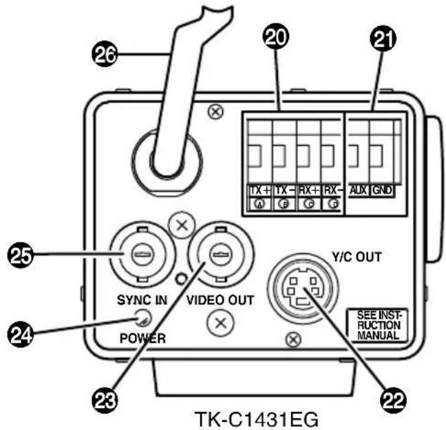
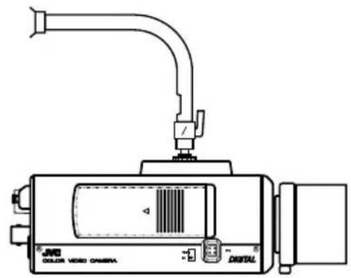
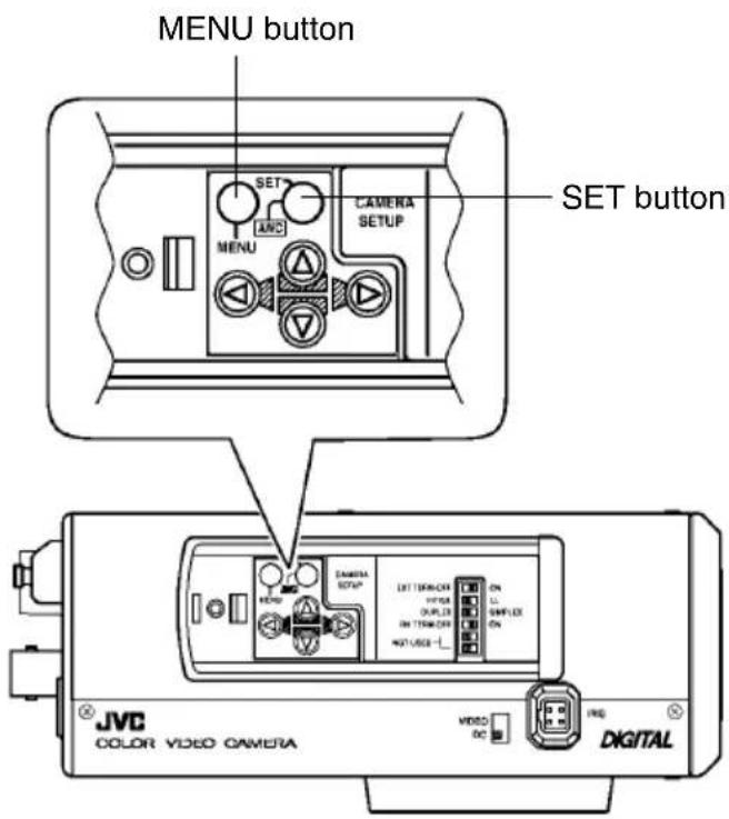
Controls, Connectors and Indicators
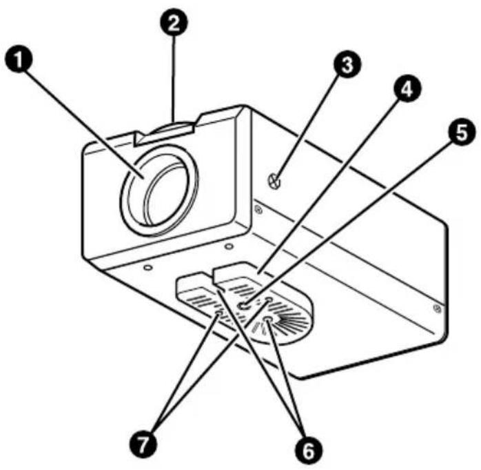
① Lens mount
To attach the lens.
This is applicable to both C-mount lenses and CS-mount lenses.
② Back focus adjustment ring
Adjusting the back focus during lens installation.
When readjustment is required, loosen the locking screw ③ by turning it counterclockwise and turn the back focus adjustment ring ②.
After the adjustment, tighten the locking screw ③ again.
③ [BF LOCK] Back focus locking screw
This serves to fix the back focus-adjusting ring.
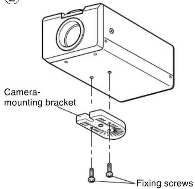
4 Camera-mounting bracket
The bracket has been attached on the bottom of the camera before shipment. It can also be attached on the top according to the circumstance.
To re-attach the bracket use the threaded holes at the top, with the camera mounting bracket fixing screws ⑦.
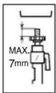
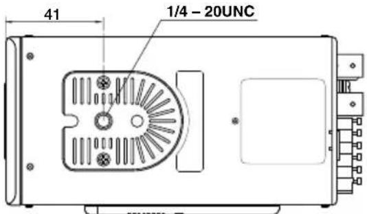
⑤ Camera-mounting screw hole (1/4 inch)
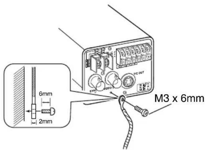
Use this hole when mounting the camera onto a fixer, pan/tilt unit, and the like. (Use a screw shorter than 7 mm.)
6 Rotation-preventive hole
Make use of this rotation-preventive hole to prevent any fall when mounting the camera. Always make sure that the camera is securely mounted.
7 Camera mounting bracket fixing screws (×2: M2.6 × 6 mm)
Be sure to use a 6 mm long screw.
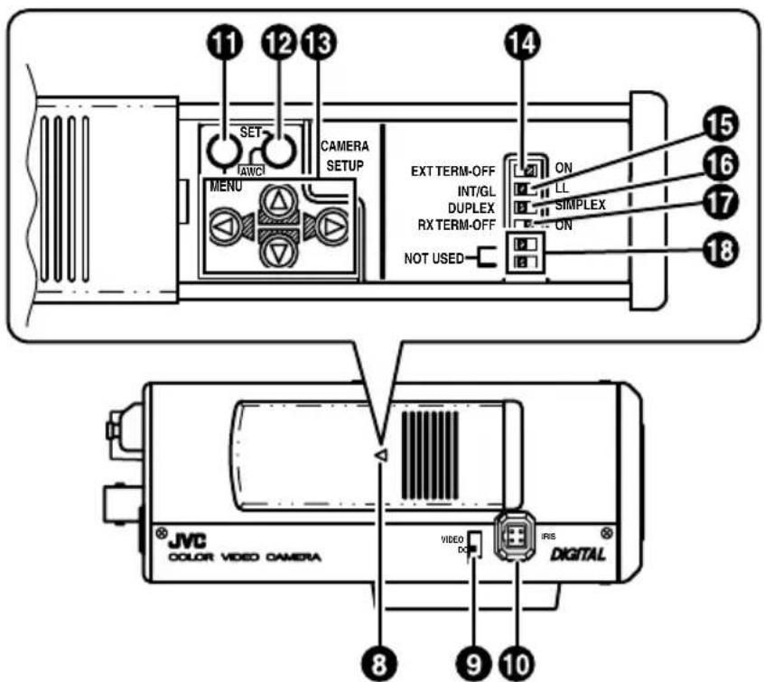
8 Cover
The cover slides open when push to the left.
9 [VIDEO/DC] Iris Selector Switch
This should be set according to the type of lens if an automatic iris control lens is used.
VIDEO: In case of lens with EE amp built-in.
DC: In case of lens without EE amp built-in.
(DC: At time of factory shipment)
10 [IRIS] Iris Terminal
This is connected to an automatic iris control lens.
( Page 15)
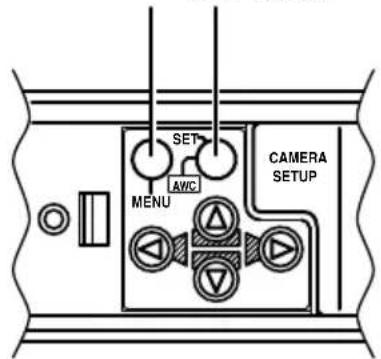
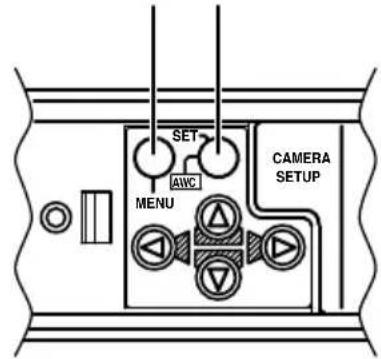
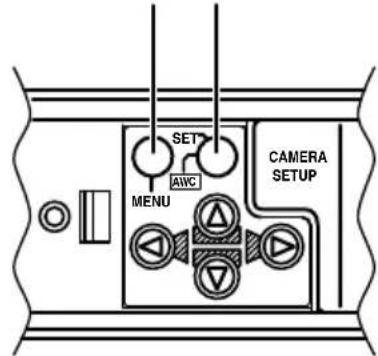
11 [MENU] Menu Button
When pressed, a menu screen is brought up.
Page 23
12 [SET/AWC] Set. Auto White Control Button
SET: Press this button to display a sub-menu.
( Page 23)
AWC: If this button is kept pressed for more than 1 second, a one-push-auto-white-balance function works and sets the white balance. Once it is set, even if colour temperature changes, white balance does not change. It is also possible to make fine adjustments on the set white balance.
(→ Page 22)
Controls, Connectors and Indicators (Continued)
13 [A, ▽] Up-and-down, left-and-right Button
These buttons select items on the menu screen and change a set value.
( Page 23)
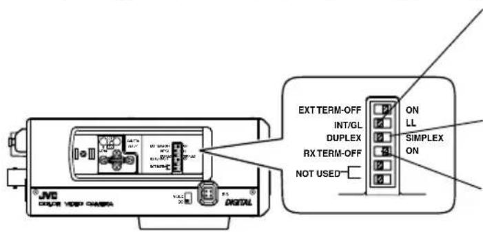
14 [EXT.TERM-ON/OFF] Terminal On/Off Switch of External Synchronization Signal
This is a terminating ON/OFF switch for the external synchronization input signal. When this is switched ON, termination is executed via a 75 Ω resistor.
ON: terminates at 75Ω.
OFF: does not terminate at 75Ω.
(ON: At time of factory shipment)
15 [INT/GL, LL] Selector Switch for Synchronizing System
This switch sets the synchronizing system for the camera.
INT/GL:
This is set for internal synchronization (INT) or external synchronization (GL).
LL (Line Lock):
The camera's vertical synchronization is locked to the AC power line frequency.
When switching between multiple cameras using a switcher, selecting this mode and adjusting the vertical phase can reduce the monitor sync disturbances occur that when the camera image is switched. (This cannot be used in regions where the power frequency is 60 Hz) (INT/GL: At time of factory shipment)
16 [DUPLEX, SIMPLEX] Selector Switch for Transmission System
If the setting is changed, be absolutely sure to switch on the power again.
DUPLEX:
This switch sets to DUPLEX when the transmission between the camera and a remote control unit is in a duplex system (two-way).
SIMPLEX:
This switch sets to SIMPLEX when the transmission between the camera and a remote control unit is in a simplex system (one-way).
(DUPLEX: At time of factory shipment)
17 [RX.TERM-ON/OFF] RX Signal Terminal ON/OFF Switch
This sets whether or not the signal between RX + and RX - on the back 20 should be terminated at the value of 110Ω resistance.
ON: Terminated.
OFF: Not terminated.
If the system including the camera is the M.DROP (Multi-drop, RS-485) system, only the last camera mounted along the control signal cable is set to "ON" and the other cameras are set to "OFF". In case of the M.DROP system, it becomes necessary to set the Machine ID. (Page 35)
If the system including the camera is the P T O P (Point to Point, RS-422A) system, set this switch of all the cameras to "ON".
The item STYLE on the COMMUNICATION screen sets M.DROP or P TO P (Page 35)
(ON: At time of factory shipment)
18 NOT USED
This cannot be used. Do not switch.
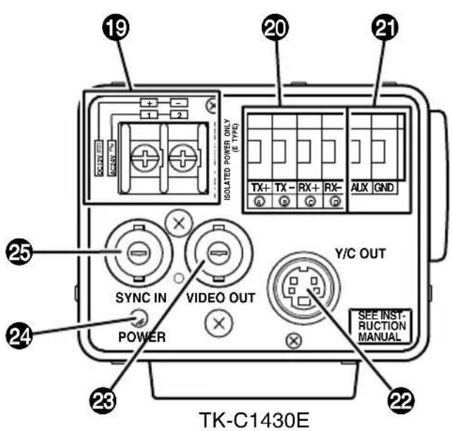
19 [DC 12V, AC 24V] Power input terminals (TK-C1430E)
To input DC 12V or AC 24V power.
20 [TX+A, TX-B, RX+C, RX-D] Control signal connection terminals
Terminals for inputting signals with electrical characteristics conforming to the EIA/TIA RS-422A or RS-485 standard.
17 RX.TERM switch
21 [AUX, GND] Auxiliary Input/Output Terminals
If there is any change in the area set on the MOTION DETECT screen, these terminals output the corresponding signals. (Page 34)
These terminals also output the B&W/COLOUR signal. (Page 30)
[Open-collector low signal. Maximum voltage 30V, current 30mA.]
When carrying out B&W/COLOUR switching using the control signal, the signals are input through these terminals. (Page 30)
[B&W: make; COLOUR: break]
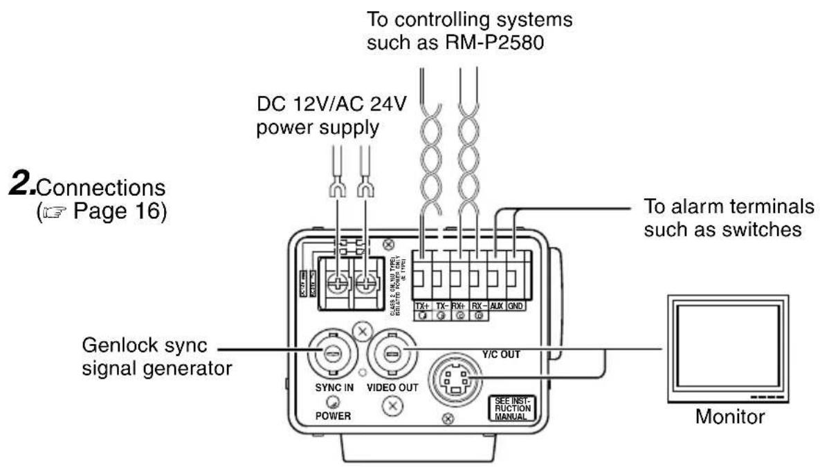
22 [Y/C OUT] Y/C output connector
This 4-pin connector outputs the luminance and chrominance signal.
- Pin configuration of Y/C OUT connector
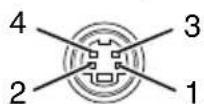
| Pin No. | Signal |
| 1 | GND |
| 2 | GND |
| 3 | Luminance (Y) |
| 4 | Chrominance (C) |
23 [VIDEO OUT] Video signal output connector
This BNC connector outputs a composite video signal. Connect this to the video input connector of a video monitor, switcher, etc.
24 [POWER] Power indicator lamp
This lamp lights when power is supplied to the camera.
25 [SYNC IN] Sync signal input connector
This BNC connector accepts the input of an external sync signal such as a composite video (VBS) or black burst (BB) signal. When a sync signal is input into this connector, the camera operation is automatically synchronized with the external sync signal.
To terminate this connector at 75Ω, turn ON the EXT.TERM switch 14.
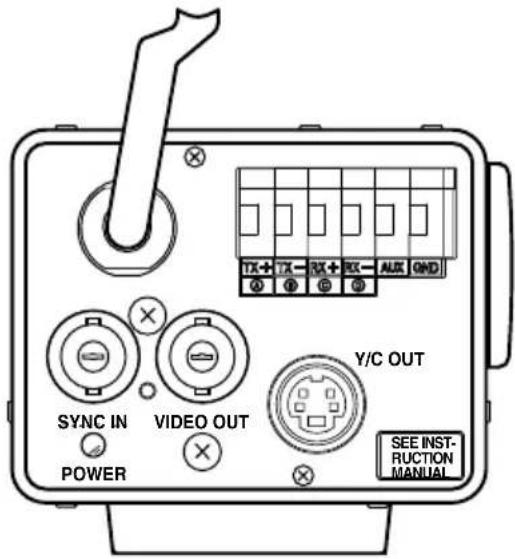
26 Power cable (TK-C1431EG)
Connect to the commercial AC (220V - 240V) outlet.
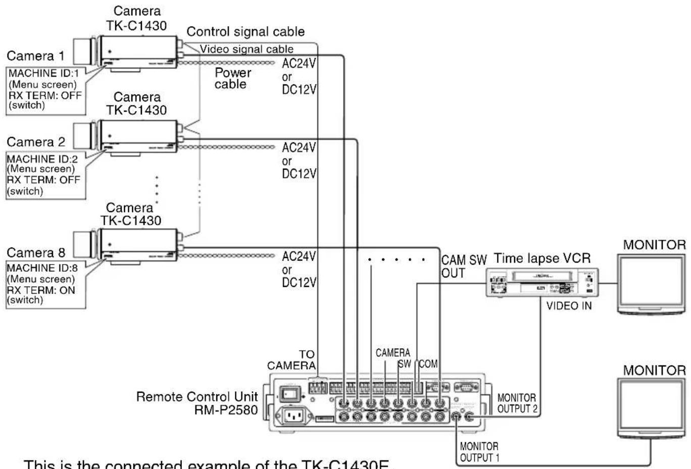
RM-P2580 System
■ System with up to 8 cameras
flowchart
graph TD
    subgraph Camera_1
        A["Camera TK-C1430"] -->|Control signal cable| B["Video signal cable"]
        C["MACHINE ID:1 (Menu screen) RX TERM: OFF (switch)"] -->|Power cable| D["AC24V or DC12V"]
    end
    subgraph Camera_2
        E["Camera TK-C1430"] -->|Power cable| F["AC24V or DC12V"]
        G["MACHINE ID:2 (Menu screen) RX TERM: OFF (switch)"] -->|Power cable| H["AC24V or DC12V"]
    end
    subgraph Camera_8
        I["Camera TK-C1430"] -->|Power cable| J["AC24V or DC12V"]
        K["MACHINE ID:8 (Menu screen) RX TERM: ON (switch)"] -->|Power cable| L["AC24V or DC12V"]
    end
    M["Remote Control Unit RM-P2580"] --> N["TO CAMERA"]
    N --> O["CAMERA SW COM"]
    O --> P["Monitor OUTPUT 1"]
    O --> Q["Monitor OUTPUT 2"]
    R["Time lapse VCR"] --> S["VIDEO IN"]
    T["MONITOR"] --> U["MONITOR"]
    style Camera_1 fill:#f9f,stroke:#333
    style Camera_2 fill:#f9f,stroke:#333
    style Camera_8 fill:#f9f,stroke:#333
    style R fill:#ccf,stroke:#333
    style T fill:#ccf,stroke:#333
    style U fill:#ccf,stroke:#333
    style S fill:#dfd,stroke:#333
    style X fill:#dfd,stroke:#333
This is the connected example of the TK-C1430E.
When controlling with any system except the RM-P2580, execute proper settings using switches and menu screens according to the systems used. (Page 14)
MEMO
- When operating a system using the RM-P2580, several cameras (up to 16) can be connected and used on one control signal cable. Consequently, an incorrect switch setting on just a single camera will cause the entire system to work incorrectly.
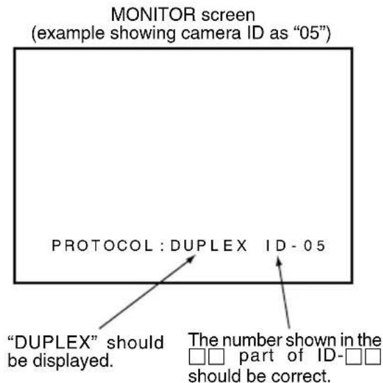
- Confirm switch settings on the screen as follows.
① Confirm that the image from the camera to be checked is displayed on the monitor.
② Turn OFF and then ON the AC power to the camera to be checked.
③ The camera begins the initial operation and characters similar to those shown in the illustration on the right appear on the monitor screen.
④ Confirm that "DUPLEX" and "ID-□□" are displayed and that the ID number is the correct number (the number should be the same as the number of the VIDEO INPUT terminal to which the camera is connected on the rear panel of the RM-P2580).
⑤ If wrong, set the camera ID again.
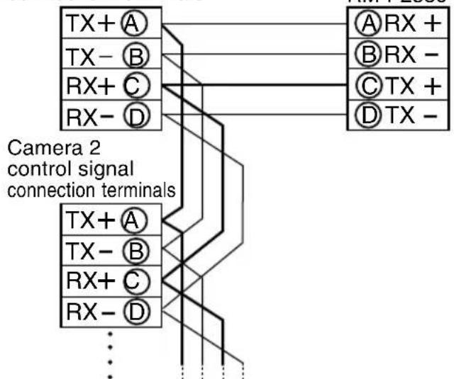
■ Connecting the control signal cable
(Use a twisted-pair cable for connection. Page 17.)
Camera 1
control signal
connection terminals
flowchart
graph TD
    A["TX + A"] --> B["A RX +"]
    C["TX - B"] --> D["B RX -"]
    E["RX + C"] --> F["C TX +"]
    G["RX - D"] --> H["D TX -"]
    I["TX + A"] --> J["TX - B"]
    K["RX + C"] --> L["RX - D"]
    M["TX - D"] --> N["TX + A"]
    O["..."] --> P["..."]
    style A fill:#f9f,stroke:#333
    style C fill:#f9f,stroke:#333
    style E fill:#f9f,stroke:#333
    style G fill:#f9f,stroke:#333
    style I fill:#f9f,stroke:#333
    style K fill:#f9f,stroke:#333
    style M fill:#f9f,stroke:#333
    style O fill:#f9f,stroke:#333
Connect:
Camera TX+ to RM-P2580 RX+
Camera TX- to RM-P2580 RX-
Camera RX+ to RM-P2580 TX+
Camera RX- to RM-P2580 TX-
The Ⓐ B Ⓒ D marks indicated on both the camera terminals and the RM-P2580 terminals facilitate correct connections. Connect the terminals with identical marks.
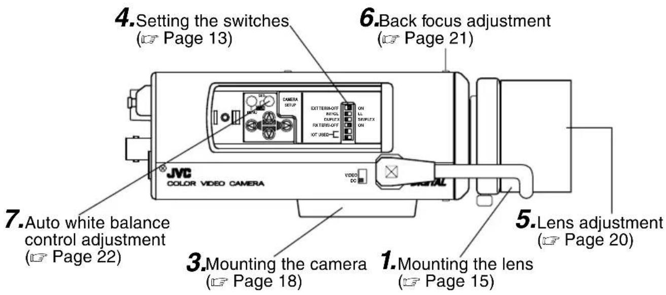
■ Setting the switches (→ Page 10)
Select the synchronization method of the camera image.
Set the switch on all cameras to LL (Line Lock) and match with the V. PHASE.
( Page 26.)
Set this switch to the DUPLEX
* If the setting is changed, be absolutely sure to switch on the power again.
Set this switch to ON (signal termination ON) only on the camera placed at the end of the control signal cable.
Set to OFF on all other cameras.
■ Setting on the MENU screen (Page 35)
* If the setting is changed, escape from the menu screen once, and definitely switch on the power again.
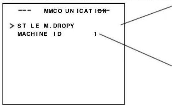
Set to M.DROP
Set to M.DROP when the RM-P2580 is used as a remote control unit. When controlling from another machine, make sure that it matches the communication system used.
MACHINE ID setting switches
Set this item to match the RM-P2580 VIDEO INPUT terminal number for each camera.
When connecting
- Turn OFF the power supply to all equipment to be used before making connections.
- Carefully read the Instructions for each piece of equipment to be used before making connections.
- For the appropriate connection cables and the length of these, carefully read "Connections on the back" on page 16.
- The control signal cable cannot be used for loop connection.
Procedures
Execute connection/installation according to the procedures described below. Turn OFF the power supply to all equipment to be used before making carefully.
This is the connected example of the TK-C1430E.
TK-C1431EG Page 17
Mounting the lens
Mount the lens according to the procedures described below.
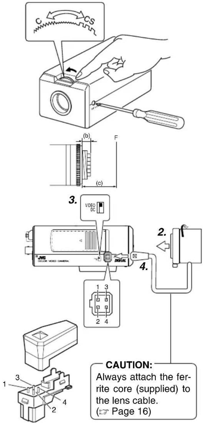
- Before mounting a lens, check whether it is a C-mount or CS-mount lens.
Tochange the mounting method, loosen the back-focus locking screw (M 2.6) using a Phillips head screwdriver, turn the back-focus adjusting ring with your fingers or the screwdriver and change the mounting method.
As regards the dimension (b) of the area to which the lens is to be installed as illustrated on the left diagram, use the one with less value than what's shown in the table below.
For both the C-mount and CS-mount, never use whatever exceeds the dimension (b), as such will not allow normal installation and damage the inner part of the camera, resulting in a malfunction.
| Lens Flange back (c) Dimension (b) | ||
| C mount lens | 17.526mm 5.5mm | or less |
| CS mount lens | 12.5mm 5.5mm | or less |
The F mark indicates a focal point.
-
Mount the lens on the camera by turning the lens clockwise. Adjust its position.
-
When using an auto-iris lens with an EE amplifier, turn the switch to the "VIDEO" side. When no EE amplifier is equipped, turn the switch to the "DC" side.
-
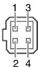
If the lens has an auto-iris mechanism, connect the lens cable after checking the pin arrangement.
If the lens cable has a different type of plug, use the 4-P plug supplied.
Attached 4 pin plugs
| Lens Pin No. (does not contain EE amplifier) (contain EE amplifier) | |||
| 1 Brake | ⊖ | 9V [max 50mA] | |
| 2 Brake | ⊕ | NC | |
| 3 | D ⊕ r i | VIDEO e | |
| 4 | D ⊖ r i | GND e | |
Installing the ferrite core
To retain electromagnetic compatibility, use the ferrite cores provided when connecting to the lens.
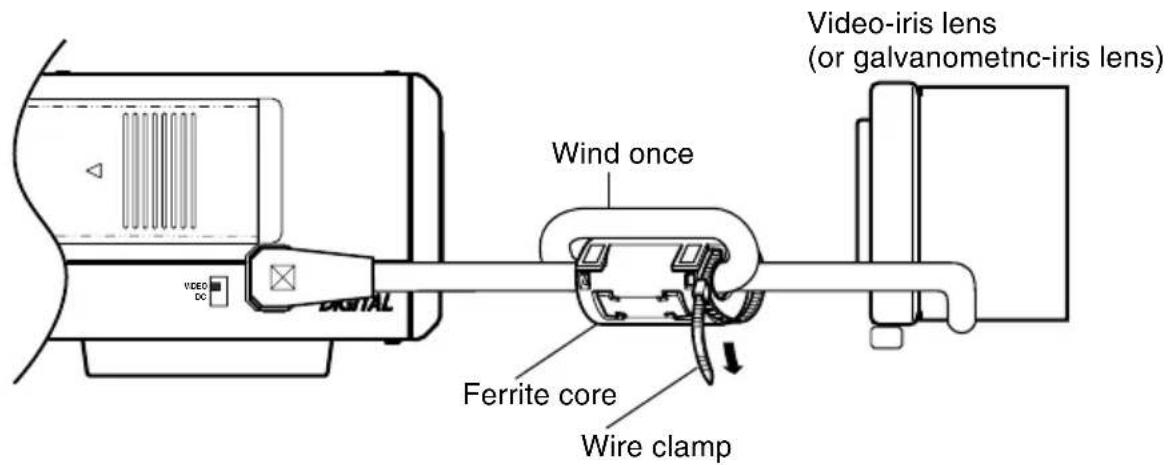
Notes:
• Install the ferrite cores within 50 mm of the camera-side connectors. (Fasten the ferrite core with the wire clamp provided.)
- If the LENS cable is short, please connect the cable to the camera without winding the cable around the ferrite core.
Connections on the back
■ Power supply
TK-C1430E (DC 12 V or AC 24V)
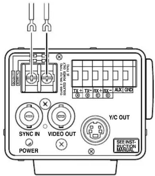
Connect the DC 12 V or the AC 24 V power supply to the DC 12V/AC 24V terminals. To prevent connection errors or a cable disconnection, we recommend the use of lug plates for the connections.
The following table shows the connection distances and connection cables provided that 2-conductor VVF cables (vinyl-insulated vinyl sheath cables) are used.
| Maximum extension (reference) | 100 m | 260 m | 410 m | 500 m |
| Conductor diameter | 1.0 mm and more | 1.6 mm and more | 2.0 mm and more | 2.6 mm and more |
MEMO
- If thin cables are used (i.e. with a high resistance), a significant voltage drop will occur when the unit is at its maximum power consumption. Either use a thick cable to restrict the voltage drop at the camera side to below 10%, or place the power supply near to the camera. If voltage drop occurs during operation, the performance will be unstable.
- Attach the cable conductors so that they do not come into contact with the drop prevention wires.
- Do not allow input from both a DC 12 V and AC 24 V power supply at the same time.
- When using a DC 12 V power supply, ensure that the polarities of the cable are correct.
• The AC 24 V power supply should conform to the following: Isolated power supply only
TK-C1431EG (AC220V - 240V)
■ Control signal cables
These cables should be connected only when it is required to control the camera using the RS-442A or RS-485 signals. The use of 0.65 4-conductor twisted pair cables is recommended. With these cables, the maximum extension distance is 1,200 m.
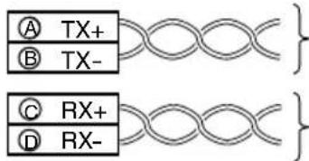
Connect to the other side in pairs like this.
Connect to the other side in pairs like this.
Power cable connect to the commercial AC220V - 240V outlet
CAUTION:
When you use this camera, the socket-outlet shall be installed near equipment so as to disconnect easily.
■ Genlock connection
With some systems, when the external sync signal is a composite video or black burst signal genlocking by applying an external sync input requires the horizontal phase (H PHASE) and colour phase (SC COARSE) to be adjusted.
MEMO
- Genlocking is not possible with a signal containing too much jitter, such as a VCR or videodisc playback signal.
- F or details, consult a JVC authorized dealer.
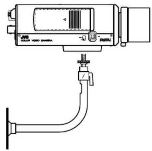
Mounting the camera
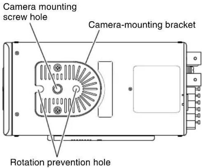
When mounting the camera on a fixer, pan/tilt, etc., use the camera mounting screw hole located on the camera-mounting bracket.
CAUTION:
Use the screw with a length shorter than 7mm from a camera-mounting face.
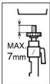
Furthermore, make use of the rotation prevention hole to prevent the camera from falling and securely mount the camera.
Special precautions must be taken for mounting the camera on a wall or a ceiling. We are not liable for any damage caused by improper installation.
Fall Prevention
- Exercise maximum caution when installing the unit to the wall or ceiling. You should not engage in the installation work yourself. Ask a professional to do the job, since the fall of the unit can result in injuries and accidents.
- When installing the unit on a fixer, Pan/Tilt unit, etc., make sure to install it firmly using a rotation-preventing hole provided to prevent fall.
- To prevent fall, connect the unit to a section with sufficient strength (ceiling slab or channel) using a fall prevention wire such as a wire chain and the like. Use the black screw on the back of the unit for installation.
Pay utmost attention to the length of the wire, too. - Specified screw (M3 × 6 mm) Never use any screw longer than the specified length as the inside can be damaged.
1
②
③
Installation of camera
- Mounting from the bottom
This camera is originally designed to be mounted from the bottom, as shown ①. The hole is standard photographic panhead screw size (1/4-20 UNC). Example the Fixing unit or Pan/Tilt unit.
- Mounting from the top
Remove the CAMERA MOUNTING BRACKET from the bottom of the camera by removing two fixing screws as shown ②. Attach the CAMERA MOUNTING BRACKET to the top, then mount the camera on the Fixing Unit as shown ③. Make sure that two original screws are used when mounting the CAMERA MOUNTING BRACKET. Be sure to use a 6 mm long locking screw for the camera-mounting bracket.
(This camera is used indoor and under similar conditions.)
Lens adjustment
Connect the camera according to the connection method, turn it on, display an image on the monitor, and check the image. The camera has been factory-adjusted to the best position, but it may need to be adjusted according to the object conditions or combination of lenses. If the image is unnatural, adjust it as follows: (Also read the instruction manual of the lens.)
LEVEL
adjustment
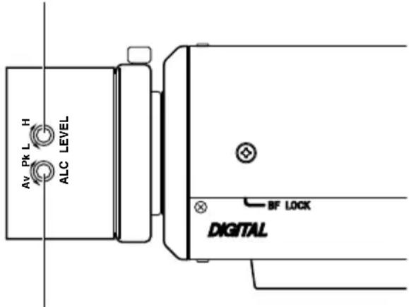
ALC adjustment
(Does not operate.)
MEMO
Note that the lens cannot make ALC adjustments. Make ALC adjustments using the item AVERAGE: PEAK on the menu.
( Page 26)
- LEVEL adjustment
| Monitor screen | LEVEL turning direction |
| Too bright Counterclockwise (Toward L) | |
| Too dark Clockwise (Toward H) | |
MEMO
- If the sensitivity adjustment LEVEL is turned excessively to L, the sensitivity increases because of the AGC function of the camera, and the image looks grainy.
- If the video iris lens is set to too low a level, malfunction such as the hunting phenomenon, in which the iris opens or closes unintentionally, may occur.
In such a case, first set LEVEL potentiometer on the lens to the H (iris open) position then adjust it to the optimum level.
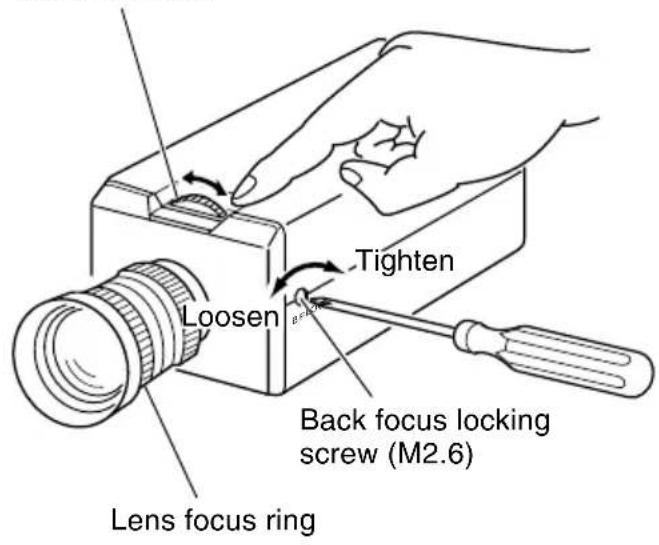
Back focus adjustment
■ Back focus adjustment
Be sure to make back-focus adjustments when changing the lens mounting method or using a different lens. If required, adjust it as follows:
- To make accurate back focus adjustments, use the electronic shutter and the ND filter, and carry out the following adjustments in a state where the lens iris is released. (The ND filter acts to reduce the amount of incident light entering the lens evenly over the entire wavelength band.)
Back focus
adjustment ring
MEMO
- LENS FOCUS ADJUSTMENT MODE At the time of focus adjustment, press the button Ⓐ at the side of the unit for at least one second to open the lens iris and to facilitate focusing. At this time, “LENS FOCUS ADJUSTMENT MODE” will be displayed on the monitor screen.
When the adjustment has been completed, press one of the buttons Ⓓ️ to cancel focus adjustment mode.
- Focus setting can differ on the colour and on the black and white screen. Make adjustments so that the focus will come to the optimum on both screens.
- With a fixed-focus lens
If the focus can not be adjusted correctly by rotating the lens focus ring, adjust the back focus as follows.
- Loosen the back focus locking screw by turning it counterclockwise ( ) with a screwdriver.
- Shoot a pattern closely.
- Turn the lens focus ring to .
- Turn the back focus adjustment ring to focus at the best point.
- Tighten the back focus locking screw by turning it clockwise ( ).
- With a zoom lens
If the image is out of focus when zooming (telephoto wide-angle), adjust the camera as follows:
- Loosen the back focus locking screw by turning it counterclockwise ( ) with a screwdriver.
- Shoot a comparatively dark scene with thin lines.
- Set the lens to the maximum telephoto position, and adjust the lens focus.
- Set the lens to the maximum wide-angle position, and turn the back focus ring to adjust the focus.
(Repeat steps 3. and 4. two or three times.) - Tighten the back focus locking screw by turning it clockwise ( ).
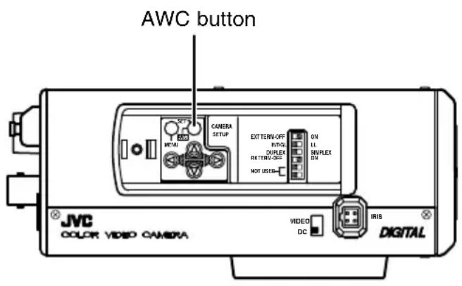
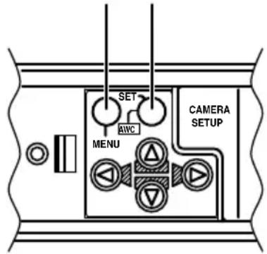
Auto white balance control adjustment
Each light source has its own colour temperature. Therefore, when the main light source lighting an object is changed, the white balance should be adjusted again by pressing the AWC button.
DURING OPERATION
DISPLAYING RESULT
OBJECT ERROR
LOW LIGHTING
OVER LIGHTING
- Place a white object under the same lighting condition as the object to be shot and zoom in to fill the screen with white.
- When the AWC button is pressed for approx. one sec., the white balance is adjusted for the object being recorded.
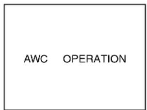
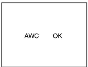
-
During the time when the Auto White function is operated, "AWC OPERATION" is displayed (for approx. 0.5 sec.). When the appropriate white balance is acquired, "AWC OK" is displayed.
-
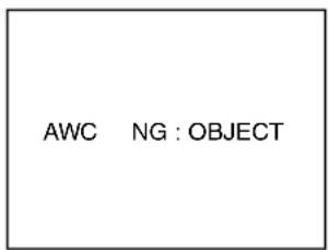
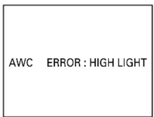
Error message display
- NG : OBJECT
Displayed when there is not enough white colour on an object or the colour temperature is not suitable.
By taking a shot of a white object to fill the screen, adjust the white balance again.
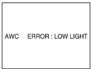
- ERROR : LOW LIGHT
Displayed when the light is low. Increase the illumination then re-adjust the white balance.
- ERROR : HIGH LIGHT
Displayed when the light is too bright. Decrease the illumination then re-adjust the white balance.
MEMO
Even if you press the AWC button, the white balance will not be re-adjusted during the operation in the black-and-white mode.
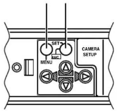
Setting the menu
-
Press the MENU button. The MENU screen is displayed.
-
Set the cursor (>) to a desired sub-menu using the Ⓐ, Ⓥ button.
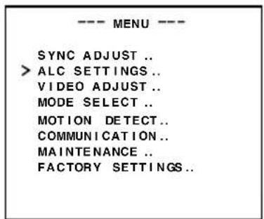
- Press the SET button. The selected sub-menu screen is displayed.
- Use the Ⓐ button to set the cursor (>) to a desired item.
- Change the set value using the 🔊, 🔒 button.
Change of the set value displays a change mark (*).
If you wish to change the set values of another items, repeat items 2. to 5. above.
- Press the MENU button.
The screen returns to the previous one (MENU screen).
- Press the MENU button.
The screen returns to the normal screen (quitting the menu display).
* When the setting is executed using the RM-P2580, use a joy stick instead of the △ ▽ button.
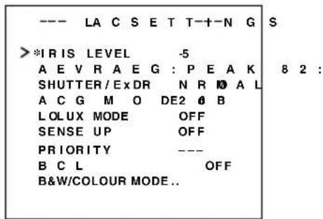
The flow of menu screen
flowchart
graph TD
    A["Page 26"] --> B["Page 31"]
    B --> C["Page 37"]
    C --> D["Page 34"]
    D --> E["Page 39"]
    E --> F["Page 42"]
    F --> G["Page 42"]

    subgraph Page 26
        H["--- MENU ---"]
        I["SYNC ADJUST."]
        J["ALC SETTINGS."]
        K["VIDEO ADJUST"]
        L["MODE ESLECT .."]
        M["MOTION DETECT .."]
        N["COMMUNICATION"]
        O["MAINTENANCE.."]
        P["FACTORY SETT INGS."]
    end

    subgraph Page 31
        Q["--- VIDEO ADJUST ---"]
        R["WHITE BALANCE ATW"]
        S["COLOUR LEVEL NORMAL"]
        T["ENHANCE LEVEL NORMAL"]
        U["PEDESTAL LEVEL NORMAL"]
        V["AUTO BLACK C TL OFF"]
    end

    subgraph Page 37
        W["--- WHITE BALANCE CONTROL---"]
        X["AWC SET.."]
        Y["R :............: B"]
        Z["MX :............: G"]
    end

    subgraph Page 34
        AA["--- MOTION DETECT ---"]
        AB["MODE OFF"]
        AC["LE BL NORMAL"]
        AD["AREA EDI T.."]
        AE["ALARM TIME 10s"]
        AF["DE MONSTRATION .."]
    end

    subgraph Page 39
        AG["Grid Grid"]
    end

    subgraph Page 42
        AH["--- MAITE NANCE ---"]
        AI["CD SPOT .."]
    end

    subgraph Page 42
        AJ["--- CCDS POT ---"]
        AK["--- ONCEL EXECUTE"]
        AL["heat up 30min In advance need Lens-cap to execute"]
    end
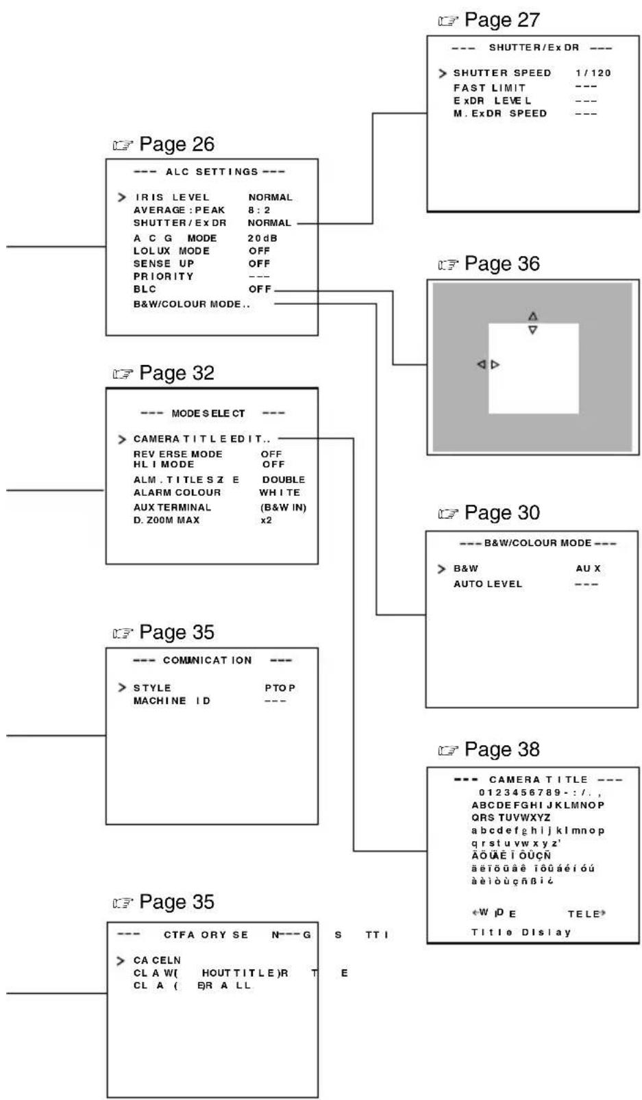
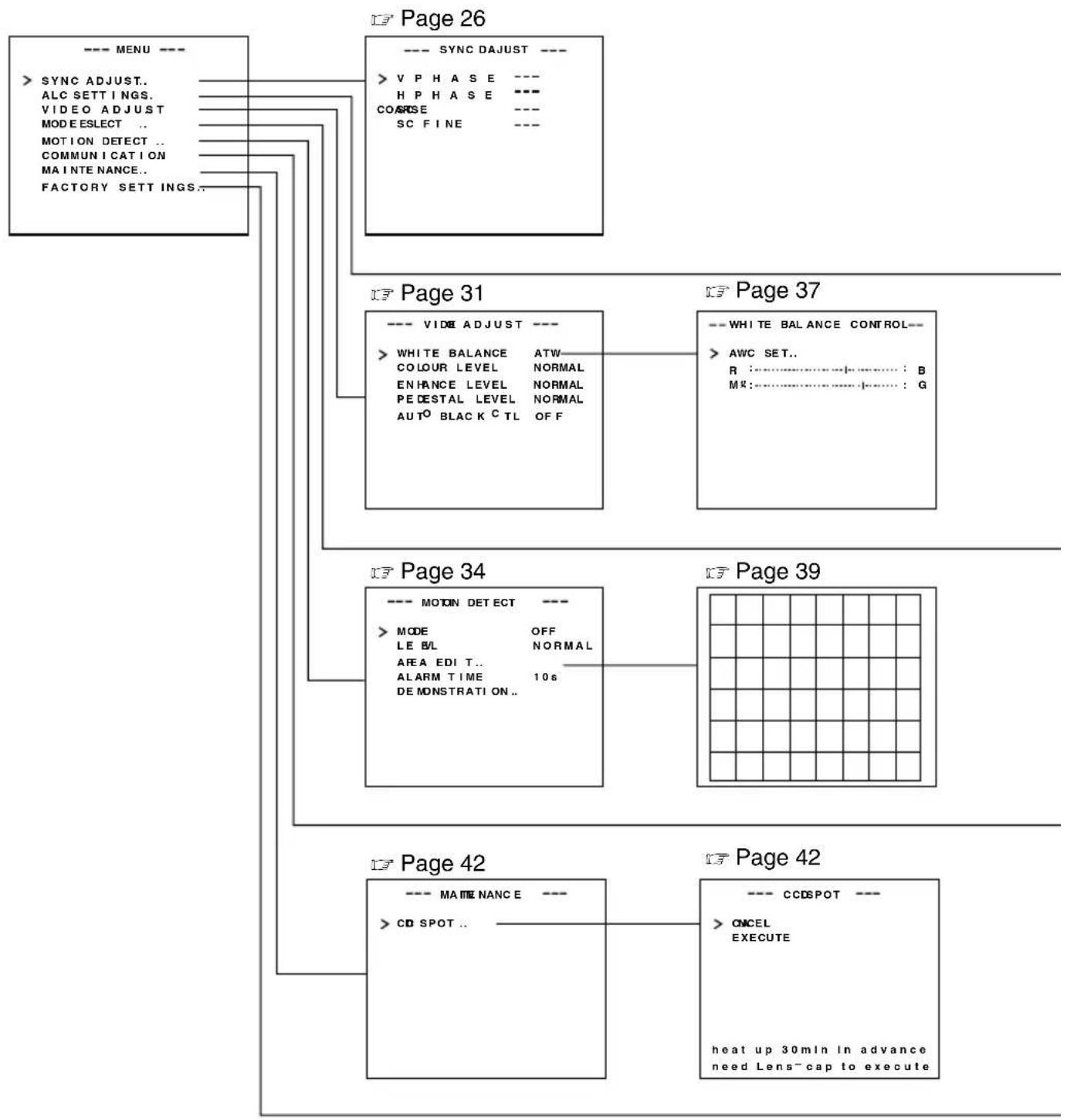
flowchart
graph TD
A["Page 26"] --> B["Page 27"]
B --> C["Page 36"]
C --> D["Page 30"]
D --> E["Page 38"]
E --> F["Page 35"]
subgraph Page 26
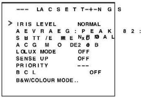
G["--- ALC SETTINGS ---"]
H["> IRIS LEVEL NORMAL"]
I["AVERAGE: PEAK 8:2"]
J["SHUTTER/EX DR NORMAL"]
K["A C G MODE 20dB"]
L["LOLUX MODE OFF"]
M["SENSE UP OFF"]
N["PRIORITY ---"]
O["BLC OFF"]
P["B&W/COLOUR MODE.."]
end
subgraph Page 32
Q["--- MODE SELECT ---"]
R["> CAMERA TITLE EDIT.."]
S["REVERSE MODE OFF"]
T["HLI MODE OFF"]
U["ALM. TITLES Z E DOUBLE"]
V["ALARM COLOUR WHITE"]
W["AUX TERMINAL (B&W IN)"]
X["D. ZOOM MAX x2"]
end
subgraph Page 35
Y["--- COMMUNICATION ---"]
Z["> STYLE PTOP MACHINE ID ---"]
end
subgraph Page 38
AA["CAMERA TITLE ---"]
AB["0123456789-:/.., ABCDEFGHijklMNOP QRS TUVWXYZ abcdefghijklmnop qrstuvvxyz' AOUAE IOUÇN aetouae iouaeióu aeiouçnič"]
AC["*WjE TELE* Title Display"]
end
subgraph Page 35
AD["--- CTFA ORY SE N---G"]
AE["> CA CELN CLA W( HOUTTITLE)R T CL A ( BR A LL E"]
end
SYNC ADJUST Screen
This executes the setting regarding synchronization.
| Item Functions and set values Initial value | ||
| V PHASE | This adjusts the vertical synchronization to those of other cameras when a selector switch for the synchronizing system on the side is at LL. (50Hz power region only.)When it is not set to LL, “---” will appear, disabling change the set value.[Set value: -156 to 0 to 156] | 0 |
| H PHASE | This adjusts the horizontal synchronization to those of other cameras and systems when a selector switch for the synchronizing system on the side is at INT/GL.When external signals are not input, “---” will appear, disabling change the set value.[Set values: -16 to 0 to 16] | 0 |
| SC COARSE | Coarse adjustment of the SC phase in gen-lock operation.The SC phase can be varied by up to 90° in each direction.Adjust with reference to another camera (or system) and together with the SC FINE adjustment.Adjust SC COARSE and SC FINE only after adjusting H PHASE.When it is not set to GL, “---” will appear, disabling change the set value.[Set values: 0°, 90°, 180°, 270°] | 0° |
| SC FINE | Fine adjustment of the SC phase in gen-lock operation.When it is not set to GL, “---” will appear, disabling change the set value.[Set values: 0 to 255] | 128 |
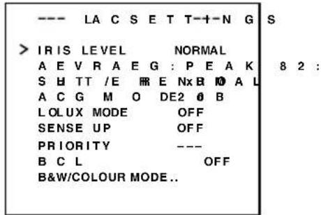
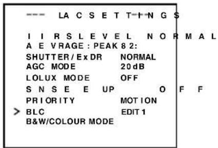
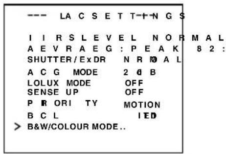
ALC SETTINGS Screen
This makes automatic adjustments according to brightness.
| Item Functions and set values Initial value | |||
| IRIS LEVEL | Adjusts the brightness level of the video signal.To lower the brightness level ... Decrease the valueTo raise the brightness level .... Increase the value[Set values: -5 to NORMAL to 5] | NORMAL | |
| AVERAGE: PEAK | Sets the exposure detection as a ratio of the average value and the peak value.A VERAGE value large: Increase the AVERAGE value when portions other than the highlighted areas of the screen are dark and look corrupted. (Ex. 10:0)PEAK value large: Increase the PEAK value when halation occurs in the highlighted areas of the screen.(Ex. 5:5)[Set values: 10:0, 9:1, 8:2, 7:3, 6:4, 5:5] | 8 : 2 | |
| Item Functions and set values Initial value | |||
| SHUTTER/ExDR | This sets the electronic shutter as well as the ExDR (Extended Dynamic Range).The use of an electronic shutter function enables shooting with proper brightness, as more brightness results in higher shutter speed.The ExDR function allows even the shooting of a subject having different luminous flux density by composing a picture shot at 1/100 sec. shutter speed with a picture shot by a high-speed shutter.NORMAL: This fixes the shutter speed to 1/50.The ExDR does not function.MANUAL: This sets the shutter speed by the item SHUTTER SPEED on the SHUTTER screen.The ExDR does not function.When SENSE UP is functioning, MANUAL cannot be selected. (Not displayed on MENU)AUTO: This automatically switches the shutter speed according to brightness.The ExDR does not function.The item FAST LIMIT on the SHUTTER (ExDR) screen sets a maximum shutter speed value.M.ExDR: This is used when shooting a subject with difference in a luminous flux density in the screen under a fixed illumination condition, and so on. During ExDR mode, the item M.ExDR.SPEED on the SHUTTER (ExDR) screen sets the composing high shutter speed. It is possible to set only when the items BLC and SENSE UP are OFF. What's more, the ExDR LEVEL sets the signal level of the composing high-speed shutter.A.ExDR: This is used when the subjects having different luminous flux densities are continuously used night and day in the situation where both indoor and outdoor subjects are mixed in existence, and so forth. During ExDR mode, the composing shutter speed automatically varies according to the contrast of a subject. This is set when shooting the subject with changing brightness.This can be set only when the item BLC is OFF.What's more, the ExDR LEVEL sets the signal level of the composing high-speed shutter.—MEMODo not set to A.ExDR when using a manual lens.When M.ExDR mode or A.ExDR mode is used, the border between a bright part and a dark part can be coloured (cyan, orange, etc.), but this is not a malfunction.When the SHUTTER/ExDR item is set to M.ExDR or A.ExDR, a flicker can occur under a fluorescent lamp, mercury lamp, etc. However, this occurs by principle of the ExDR function, and therefore this is not a malfunction. | NORMAL | |
| * When the SHUTTER (ExDR) item is set to NORMAL, the following items (SHUTTER SPEED, FAST LIMIT, ExDR LEVEL, and M.ExDR SPEED) cannot be changed. | |||
| SHUTTER SPEED | This sets a shutter speed when MANUAL is set.The AUTO, M. ExDR, A. ExDR set value is displayed as “- - -” and cannot be changed[Set values: 1/120, 1/250, 1/500, 1/1000, 1/2000, 1/4000, and 1/10000] | 1/120 | |
| Item Functions and set values Initial value | |||
| FAST LIMIT | This sets the fastest value of a shutter speed when AUTO is set.The MANUAL, M. ExDR, A. ExDR set value is displayed as “- - -” and cannot be changed. The higher the shutter speed becomes, the more smear phenomenon is emphasized, which is peculiar to the CCD.[Set values: 1/1000, 1/2000, 1/4000, 1/10000, 1/20000, 1/40000, 1/100000] | 1/100000 | |
| ExDR LEVEL | This sets the signal level of the composing high-speed shutter during ExDR mode. This is set according to the brightness of a subject.When using M.ExDR, be sure to set M.ExDR SPEED in advance.When the SHUTTER/ExDR item is set to MANUAL or AUTO, “- - -” appears, disabling setting.To give priority to the low-brightness parts of the subject... increase the valueTo give priority to the high-brightness parts of the subject... decrease the value[Set values: -5 to NORMAL to 5]——MEMO——In the case of a subject with a large difference in the luminous flux density, sometimes images do not change even if ExDR LEVEL is varied. However, this occurrence is a peculiarity of the unit and is not a malfunction. | NORMAL | |
| M.ExDR SPEED | This sets the composing high shutter speed when ExDR is set to M.ExDR.Set the shutter speed in order that a subject with a high luminous flux density (outdoor, etc.) may come out most clearly. This is displayed as “- - -” during MANUAL, AUTO or A. ExDR and cannot be set.[Set values: 1/500, 1/1000, 1/2000, 1/4000, 1/10000, 1/20000] | 1/4000 | |
| AGC MODE | This sets a maximum gain of the AGC (Automatic Gain Control).OFF: When the AGC function is not used.10dB: When luminous energy is insufficient.20dB: When luminous energy is extremely insufficient.SUPER: When brightness is insufficient even when it is set to 20dB.If the gain is increased, the screen gets rough in a dark place.If it is set to SUPER, it can sometimes consume operation time to cope with a drastic level change.When the item “B&W” is set to “AUTO”, [SUPER] is displayed when the item “AGC MODE” is set to “SUPER”, and [20dB] is displayed for other settings. Increase the gain up to the value displayed. | 20dB | |
| LOLUX MODE | Used when brightness is low even when setting the AGC MODE.(Functions regardless of the AGC MODE setting.)OFF: LOLUX MODE is offON: LOLUX MODE is on (+ 6dB) | OFF | |
| SENSE UP | This item makes up a sensitivity should be heightened automatically when a subject becomes dark.In case of the X32 AUTO, the sensitivity is automatically heightened up to 32 times continuously as compared with standard.As the sensitivity becomes higher, the shutter speed becomes lower, resulting in unnatural motion.If SHUTTER/ExDR is set to MANUAL or the M.ExDR, “- - -” will appear, disabling the SENSE UP function.[Set values: OFF, X2 AUTO, X4 AUTO, X8 AUTO, X16 AUTO, X32 AUTO]——MEMO——When the magnification of SENSE UP is enhanced, the screen can become coarse or whitish, or whitish flaws can emerge sometimes, but this is not abnormal.When the item SENSE UP is set other than to OFF, a flicker can occur under a fluorescent lamp, mercury lamp, etc. However, this occurs by principle of SENSE UP, and therefore this is not a malfunction. | OFF | |
| PRIORITY | This item sets the order in which the AGC and slow shutter speed decrease function when the object brightness becomes low.If B&W item of the B&W/COLOUR mode is set to AUTO, and the AGC MODE item or the SENSE UP item is set to OFF, “- - -” will appear, disabling any setting.MOTION: Priority is given to motion.This is suitable to a subject with quick motion, since the AGC (automatic gain control) functions with priority when the subject becomes dark.PICTURE: Priority is given to image.When the subject becomes dark, SENSE UP (sensitivity goes up) functions with priority, offering suitability that gives priority to image. | MOTION | |
| BLC | Sets the backlight compensation function. Set when a bright light source, etc. is placed in the same direction as the subject.If the item SHUTTER/ExDR is set to the M.ExDR or the A.ExDR, “- - -” will appear, and the BLC does not function.OFF: The backlight compensation function does not work.AREA 1 to AREA 4: When the SET button is pressed, the fixed light metering areas are displayed. Select one of the four types. (Indicated positions on the screen are rough guides. Execute required settings after checking and confirming the functions on actual images.)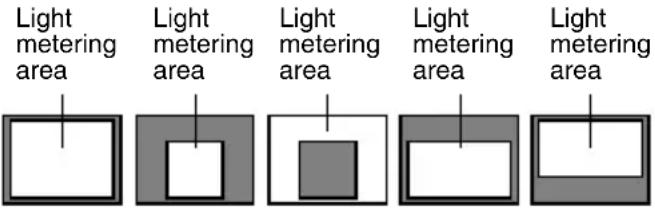 OFF AREA 1 AREA 2 AREA 3 AREA 4* The indicated position on the screen should be used as a rough guide.EDIT 1 to EDIT 2: When the SET button is pressed, the user light metering areas are displayed. Select one of the two types.“BLC EDITTING Screen” on page 36. OFF AREA 1 AREA 2 AREA 3 AREA 4* The indicated position on the screen should be used as a rough guide.EDIT 1 to EDIT 2: When the SET button is pressed, the user light metering areas are displayed. Select one of the two types.“BLC EDITTING Screen” on page 36. | OFF | |
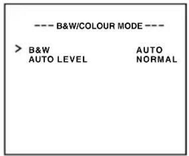
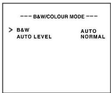
| B&W COLOUR MODE .. | This function sets the colour modes to colour or B&W.When switching the mode between “colour” and “B&W” is carried out, the focus may be dislocated. In such a case adjust the focus again. | ||
| B&W | Switches the mode from colour to B&W and visa-versa.OFF:Turns the B&W mode switching function off.ON:Sets the camera permanently to B&W mode.AUTO:The camera automatically switches to Colour mode when the object is bright and B&W mode when it is dark.(Page 40)AUX:B&W/COLOUR switching is carried out according to the signal input from the AUX terminal.(Page 41)—MEMOIf AUTO is selected as the B&W item, the B&W/COLOUR setting can be switched as appropriate according to the brightness of the object, but illumination and screen conditions may make this impossible. Moreover, when you use infrared illumination, if the subject excessively reflects, a B/W screen can switch to a colour screen. To make absolutely certain of B&W/COLOUR switching, set to AUX and input the control signal to the AUX terminal.If AUX is selected as the B&W item, the AUX TERMINAL item is automatically set to B&W IN. If this changes to anything other than AUX, the AUX TERMINAL item reverts to the value set before the change was made.(Page 33.) | AUX | |
| AUTO LEVEL | When the “B&W” function is set to “AUTO”, this function sets the signal level of the object at which the camera will automatically switch to B&W mode.LOW:Switches to B&W mode when the signal level of the object indicates low illumination.NORMAL:Switches to B&W mode when the signal level of the object indicates medium illumination.HIGH:Switches to B&W mode when the signal level of the object indicates high illumination.—MEMOWhen the item “B&W” is set to other than AUTO, “- - -” is displayed and the settings to the item “LEVEL” cannot be varied. | NORMAL | |
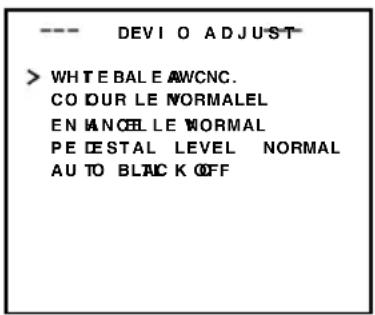
VIDEO ADJUST Screen
Adjustments are made on video signals.
| Item Functions and set values Initial value | ||
| WHITE BALANCE | Selects the white balance adjustment function. The white balance can be adjusted manually or automatically for light within the colour temperature range of 2500K to 8000K.A TW: Auto-Tracking White Balance mode.This automatically adjusts the white balance.A WC: Auto White Balance Controll mode. When the SET button is pressed, the adjustment screen appears.(See page 37.)—MEMOThe “-- -” will appear during operation in the black-and-white mode and any setting cannot be changed. | ATW |
| COLOUR LEVEL | To adjust the colour level of the video signal.T o make colours lighter ... Decrease the valueT o make colours darker ... Increase the value[Set values: -5 to NORMAL to 5]—MEMOThe “-- -” will appear during operation in the black-and-white mode and any setting cannot be changed. | NORMAL |
| ENHANCE LEVEL | To adjust the contour enhancing level of the video signal.T o make the picture quality harder ... Increase the valueT o make the picture quality softer ... Decrease the value[Set values: -5 to NORMAL to 5] | NORMAL |
| PEDESTAL LEVEL | To adjust the pedestal level of the video signal.T o brighten picture ... Increase the valueT o darken picture ... Decrease the value[Set values: -5 to NORMAL to 5] | NORMAL |
| AUTO BLACK CTL | This is set when it is difficult to view a dark part of the image even if gain is boosted by the AGC (automatic gain control).ON: When a black level of the image signal is low, a pedestal level that becomes the standard of black is automatically elevated, making it easier to view a dark part.OFF: AUTO BLACK does not function.—MEMOWhen PEDESTAL LEVEL is set to 5, no function can take place even if AUTO BLACK CTL is ON.When AGC MODE is set to OFF, no function can take place even if AUTO BLACK CTL is ON. | OFF |
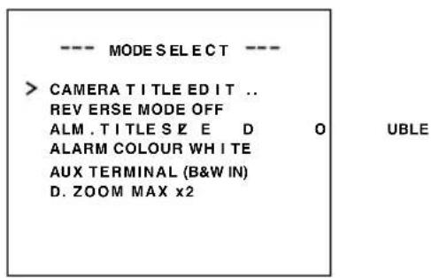
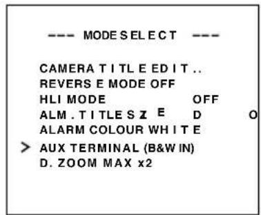
MODE SELECT Screen
Titles, image reversion, etc., are set.
| Item Functions and set values Initial value | ||
| CAMERA TITLE EDIT | Bring up the CAMERA TITLE, EDIT screen.(Page 38) | - |
| REVERSE MODE | Settings are executed for image reversion.OFF: Image does not reverse.U-D: Up and down of the image are reversed.R-L: Left and right of the image are reversed.ALL: Up and down and left and right of the image are reversed. | OFF |
| HLI MODE | The highlighted part of the image is made black to make the surroundings of the highlighted part better visible. Set to HIGH when there are many highlighted parts.[Set values: OFF, LOW, MIDDLE, HIGH] | OFF |
| ALM.TITLE SIZE | Set the size of the characters displayed in the case of alarms.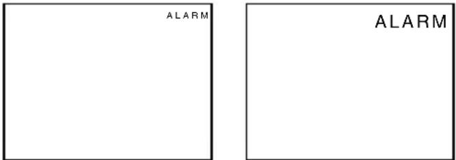 NORMAL DOUBLE NORMAL DOUBLE | DOUBLE |
| ALARM COLOUR | This sets the colour of an alarm title.[Set values: WHITE, GREEN, CYAN, YELLOW]—MEMOIn the ALARM mode, the colour of camera title appears in the ALARM COLOUR set. | WHITE |
| AUX TERMINAL | For setting the signal input or output of the AUX terminal.MOTION: A signal is output if there is a change in the area set on the MOTION DETECT screen.B&W OUT: A signal is output when the camera switches to B&W or Colour mode.B&W IN: Set to this position when inputting the B&W/Colour switching control signal to the AUX terminal. (17 Page 11, 30.)—MEMOIn setting B&W OUT, if you use an infrared illuminator in link motion, hunting can occur. To prevent this, we recommend that you link in motion this unit and the infrared illuminator, etc., by control signals after setting to B&W IN.If the B&W item is set to AUX, the AUX TERMINAL item changes to [B&W IN] and can not be changed. | (B&W IN) |
| D.ZOOM MAX | This function sets the maximum zoom ratio of the electronic zooming.[Set values: x1, x2, x4, x6, x8, x10]—MEMOThe electronic zoom function can only be used by the communication command of exclusive controllers (RM-P2580, etc.).Note Picture quality deteriorates under electronic zooming as it is accompanied by digital image processing.When the electronic zoom magnification ratio is increased, there may be blurring in the upper center left of the screen. This is a characteristic of the main unit and is not a malfunction. | x2 |
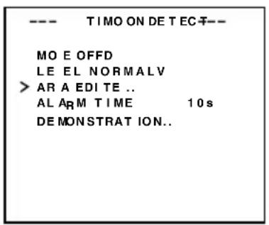
MOTION DETECT Screen
Settings are executed about the motion detecting function that emits alarm signals when there exists any motion in the image. Alarm signals are output from the auxiliary terminals on the back.
| Item Functions and set values Initial value | ||
| MODE | This sets ON/OFF of motion detecting function.OFF: Motion detecting function does not work.ON: Motion detecting function works. | OFF |
| LEVEL | This sets the level that detects motion.If the item MODE is set to OFF, “- - -” will appear, and settings cannot be changed.Tofunction with large signal level change...decrease the valueTofunction with small signal level change...increase the value[Set values: -5 to NORMAL to 5] | NORMAL |
| AREA EDIT | This sets the range in which the motion detecting function works.(Page 39) | - |
| ALARM TIME | This sets the output time of the alarm signal output of AUX terminal as well as “ALARM” display on the screen when motion is detected.If the item MODE is set to OFF, “- - -” will appear, and settings cannot be changed.[Set values: OFF, 5s, 6s, 7s, 8s, 9s, 10s, 15s, 20s, 30s, 1min]—MEMOEven when the ALARM TIME item is set to OFF, an alarm signal is output from the AUX terminal for about 500ms, and “ALARM” is not displayed on the screen. | 10s |
| DEMONSTRATION | This is used when checking and confirming the set motion detecting function. The detection area is shown in gray.(Page 39) | - |
COMMUNICATION Screen
Settings are made for the control signal-connecting terminals on the back. If the setting is changed, be absolutely sure to switch on the power again.
| Item Functions and set values Initial value | ||
| STYLE | This sets a communication system according to the system used.P T O P (Point to point)This is set when a remote control unit controls a camera.M.DROP (Multi-drop)This is set when a remote control unit controls a plural number of cameras. | P TO P |
| MACHINE ID | This is set when the STYLE item is set to M.DROP. This is the number that identifies individual cameras in a group.No proper function can be realized if an ID number is repeated within a system.A combined use with the RM-P2580 necessitates the setting together with the video input number of the RM-P2580.If the item STYLE is set to P TO P, “- - - ” will appear, and settings cannot be changed. | --- |
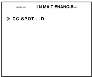
MAINTENANCE Screen
White spot compensation is performed.
| Item Functions and set values Initial value | ||
| CCD SPOT | The white spots on the screen, which are characteristic for CCDs can be reduced. Page 42 “White Spot Compensation” | - |
FACTORY SETTINGS Screen
Set values are returned to initial values.
| Item Functions and set values Initial value | ||
| FACTORY SETTINGS | The values set on the menu are returned to initial values.CANCEL: No return to the initial value.CLEAR: Returns set values except titles to the (WITHOUT TITLE) initial value.CLEAR (ALL): Returns all set values including titles to the initial value.Select respective set value and press the SET button.Then, “DATA CLEARED” will appear for about 3 seconds.Be sure not to switch off the power while the display is still on.—MEMOHowever, when FACTORY SETTINGS by means of transmitted commands, the contents of the COMMUNICATION menu do not return to the factory settings. | — |
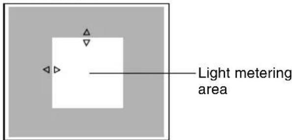
BLC EDITTING Screen
It is possible to set freely the light metering area for backlight compensation. The 2 screens of EDIT1 and EDIT2 can be set.
EDIT 1 screen

SET button
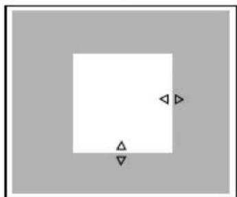
natural_image
Simple geometric diagram with a square and two triangles inside, no text or symbols presentEDIT 2 screen

SET button
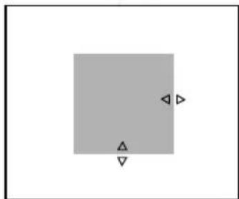
natural_image
Simple geometric diagram with a gray square and two triangles, no text or symbols present* The indicated position on the screen should be used as a rough guide.
MENU button SET button
- Set the item BLC on the ALC SETTING screen to EDIT1.
- Press the SET button.
The EDIT1 screen is brought up.
- Set the upper side and left side of the metering area using the Ⓐ button.
The sides having marks can be changed.
- Press the SET button.
The changeable sides of the metering area move to the right side and base side.
- Set the base and right side of the metering area using the Ⓓ button.
If the SET button is pressed once more, the two changeable sides of the metering area return to the top and left sides. (The EDIT2 screen can also be set likewise)
- Upon completion of setting, press the MENU button.
The screen returns to ALC SETTING SCREEN.
* To use the set metering area, set the item BLC to EDIT1 or EDIT2.
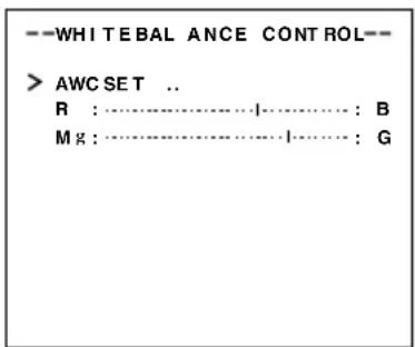
Manual Adjustment of White Balance
When automatic adjustment of the white balance results in a “reddish screen”, etc., adjust the white balance manually.
MENU button SET button
VIDEO ADJUST screen
WHITE BALANCE
CONTROL screen
- Set the WHITE BALANCE item on the VIDEO ADJUST screen to AWC and press the SET button.
* The WHITE BALANCE adjustment screen appears on the monitor.
* Select AWC SET, and press the SET button. AWC (white balance adjustment) is performed, and the WHITE BALANCE CONTROL screen appears on the monitor.
- Select the hue to be adjusted. (R/B or Mg/G)
Press the Ⓓ or Ⓥ button.
- Adjust the hue.
Press the ◀ or ▶ button.
* The “1” indicator moves in accordance with the setting. When a setting is changed, the “+” mark appears at the original position.
- Concluding manual white balance adjustment.
Pushing the MENU button returns the screen to VIDEO ADJUST.
MEMO
If the mode is changed from colour to black-and-white during the colour phase adjustment on the WHITE BALANCE CONTROL screen, the VIDEO ADJUST screen will be brought back. At this time, any adjusted value will not be saved.
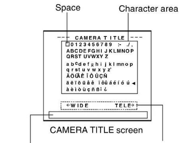
CAMERA TITLE Setting
Up to 24 characters can be selected as camera text for each camera. The set characters are displayed at the bottom of the screen.
SET buttonMENU button
MODE SELECT screen
Title input area
Displayed when making communication settings only
- Select the item CAMERA TITLE on the MODE SELECT screen, and push the SET button. Then, the CAMERA TITLE screen is brought up.
- Select the first character from the character area using Ⓐ️◀▶ buttons.
The selected character is displayed flashing on and off.
- Push the SET button.
The first character gets fixed and the blinking title input area moves to the second character.
- Repeat the above items 2 to 3.
It is possible to use up to 24 characters to input the title.
- Push the MENU button.
The screen returns to MODE SELECT.
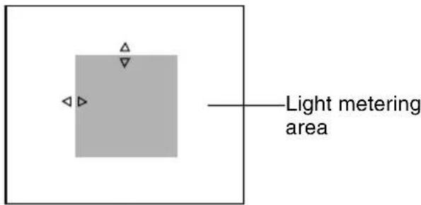
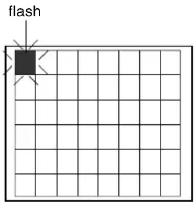
Setting the MOTION DETECT Function
It is possible to set freely the area where MOTION DETECTING functions.
MOTION DETECT screen
Setting screen
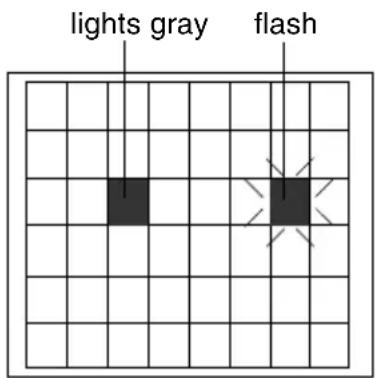
- Select the item AREA EDIT on the MOTION DETECT screen.
- Press the SET button.
The setting screen is brought up.
- Select the area not subject to detection using the △ ▽ ◀ ▶ button.
The area flashing ON and OFF in black and white moves.
- Press the SET button.
The area not subject to detection is set, and it turns gray (lights up).
To cancel the set area, press the SET button again.
- Repeat items 3 and 4 above.
- Upon completion of setting, press the MENU button.
The screen returns to the MOTION DETECT menu.
MEMO
- Indicated positions on the screen are rough guides.
Be sure to check and conform the positions on the actual screen.
* It is possible to check and confirm the set areas on the DEMONSTRATION screen. The detection area is shown in gray.
- The MOTION DETECT function does not work for about 5 seconds after exiting MENU.
The motion detector is not a feature to prevent theft, fire, etc. Even if an accident should occur resulting in damage, we do not accept any liability.
Output of Black-White/Colour switching signal
It is possible to output black-white/colour switching signal from the AUX terminal on the back of this unit. Perform the following settings.
MENU button SET button
CAUTION:
When you use near infrared ray illuminations, use a lens that is compatible with the near infrared ray illuminations. Any lens other than the compatible one can result in out-of-focus due to such characteristics.
■ Set the B&W Item to AUTO.
- Select the B&W/COLOUR MODE item on the ALC SETTING screen.
- Press the SET button. The B&W/COLOUR MODE screen appears.
- Press either the Ⓐ button or the button and select the B&W item.
- Press either the ◀button or the button and set to "AUTO".
- Upon completion of setting, press the MENU button twice. Then, the MAIN MENU screen is brought back.
■ Set the AUX TERMINAL Item to B&W OUT.
- Select MODE SELECT on the MAIN MENU screen.
- Press the SET button. The MODE SELECT screen appears.
- Press either the Ⓐ button or the Ⓥ button and select the AUX TERMINAL item.
- Press either the Ⓐ button or the button and set to "B&W OUT".
- Upon completion of setting, press the MENU button twice.
- Then, the normal screen is brought back.
MEMO
- When you use infrared illumination, if the subject excessively reflects, a B/W screen can switch to a colour screen. To perform switching with higher accuracy, we recommend that you use it by the setting mentioned in [Control by Black-White/Colour Switching Signal From the Outside], referring to Page 41.
Control by Black-White/Colour switching signal from the outside
Carry out the following setting when you link in motion the black-white/colour switching of this unit and infrared illumination, etc., using the switching signal from the outside control device.
Infrared illumination, etc.
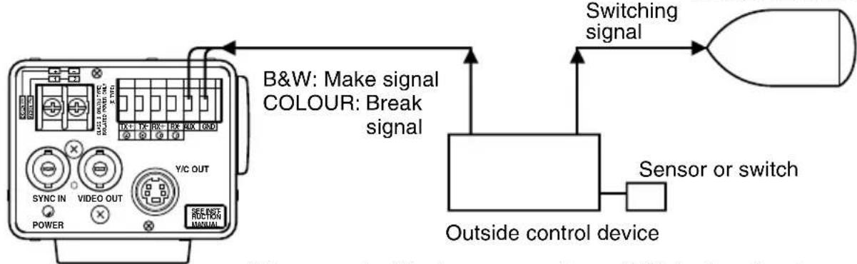
It is requested that you consult our JVC dealer about connecting devices, etc.
MENU button SET button
■ Set the B&W item to AUX.
- Select B&W/COLOUR MODE on the ALC SETTING screen.
- Press the SET button.
- The B&W/COLOUR MODE screen appears.
- Press either the ⓐ button or the Ⓥ button and select the B&W item.
- Press either the ⏻ button or the ⏱ button and set to "AUX".
Then, the AUX TERMINAL item on the MODE SELECT screen is automatically set to (B&W IN). Refer to Page 33.
- Upon completion of setting, press the MENU button.
- Then, the ALC SETTING screen is brought back.
CAUTION:
When you use near infrared ray illuminations, use a lens that is compatible with the near infrared ray illuminations. Any lens other than the compatible one can result in out-of-focus due to such characteristics.
White spot compensation
CCDs have the general characteristic that white spots appear on the screen when the CCD is operated at high temperatures or when they are used with a slow shutter speed.
This unit has a built-in white spot compensation function to reduce these white spots.
(The number and the size of the white spots changes according to the use temperature, the shutter speed, etc. Furthermore, there is a limit on the number of white spots that can be compensated.)
Operation method
-
Attach a lens cap or similar.
-
Prevent entry of light to the CCD.
-
Switch on the camera power supply and wait for at least 30 minutes.
-
Display the MAINTENANCE screen.
- Confirm that the cursor (>) is at the item CCD SPOT.
-
Press the SET button.
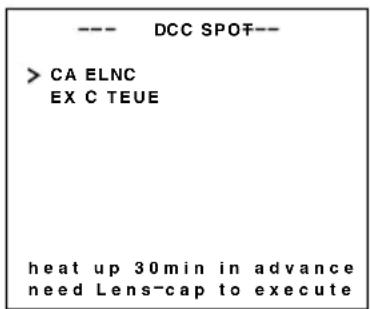
-
The CCD SPOT screen will be displayed.
-
If you do not want to perform white spot compensation, move the cursor (>) to CANCEL and press the SET button.
-
Move the cursor (>) to EXECUTE.
-
Press the SET button.
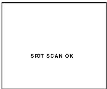
- White spot compensation will operate. ("SPOT SCAN OPERATION" is displayed during operation.)
-
Confirm the display.
-
When white spot compensation has been performed correctly, "SPOT SCAN OK" is displayed for about 5 seconds, and then return is made to the CCD SPOT screen.
-
When "SPOT SCAN ERROR: HIGH LIGHT" is displayed, check that no light enters into the CCD.
-
Press the MENU button.
- Return to the MENU screen will be made.
Specifications
Image pickup device: 1/3 type IT CCD, 752 (H) × 582 (V)
Synchronization method : Internal, Line lock, Full Genlock
Scanning frequency: (H) 15.625 kHz, (V) 50 Hz
Resolution: 480 TV lines (H)
VIDEO OUT: Composite video signal 1 V (p-p), 75 Ω (BNC)
Y/C OUT: Y: 1.0 V (p-p), 75 Ω
C: 0.3 V (p-p), 75 Ω
Video S/N ratio: 50 dB (AGC OFF)
Minimum required illumination: 0.9 lx (50 %, F1.2, AGC 20 dB)
0.45 lx (50 %, F1.2, AGC 20 dB, LOLUX MODE)
0.45 lx (25 %, F1.2, AGC 20 dB)
0.23 lx (25 %, F1.2, AGC 20 dB, LOLUX MODE)
0.03 lx (50 %, F1.2, AGC 20 dB, B&W MODE)
0.015 lx (50 %, F1.2, AGC 20 dB, LOLUX MODE, B&W MODE)
0.015 lx (25 %, F1.2, AGC 20 dB, B&W MODE)
0.03 lx (50 %, F1.2, AGC 20 dB, SENSE UP × 32)
0.014 lx (50 %, F1.2, AGC 20 dB, LOLUX MODE, SENSE UP × 32)
Communication: RS-422A or RS-485 (switchable)
9600 bit/s
Lens mount: C/CS mount
Power supply and power consumption: TK-C1430E AC 24 V ∼ 50 Hz/60 Hz, DC 12 V = 530 mA
TK-C1431EG AC 220 V – AC 240 V ∼, 50 Hz/60 Hz, 75 mA
Ambient temperature: -10 ^ to 50 ^ (operation)
0 °C to 40 °C (recommended)
Mass: TK-C1430E 620 g
TK-C1431EG 840 g
Accessory: Instructions 2 Ferrite core 1
4P plug 1
DIMENSIONS (Unit: mm)
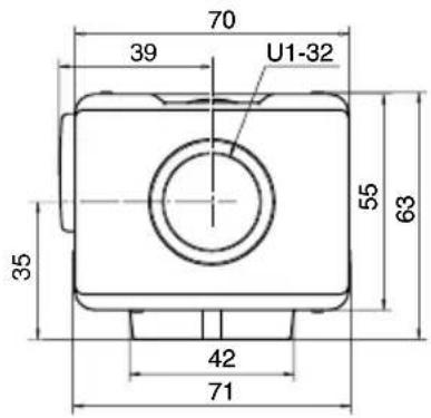
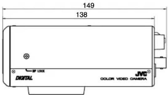
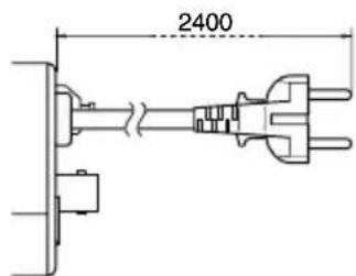
(TK-C1431EG)
Design and specifications are subject to change without notice.
JVC®
JVC ^® is a registered trademark owned by Victor Company of Japan, Limited.
JVC ^® is a registered trademark in Japan, the U.S.A., the U.K. and many other countries.
© 2005 Victor Company of Japan, Limited.
Printed in Thailand
LWT0276-001A-H