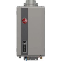
RTG-95DVELN-3 - Water heater Rheem - Free user manual and instructions
Find the device manual for free RTG-95DVELN-3 Rheem in PDF.


| Product Type | Tankless Water Heater |
| Brand | Rheem |
| Model | RTG-95DVELN-3 |
| Fuel Type | Natural Gas |
| Dimensions (W x D x H) | 17.5 in x 13.75 in x 27.5 in (44.5 cm x 34.9 cm x 69.9 cm) |
| Weight | 60 lb (27.2 kg) |
| Maximum BTU/h | 199,000 BTU/h |
| Flow Rate | 9.5 GPM (35.9 L/min) |
| Energy Factor | 0.82 |
| Venting Type | Direct Vent (PVC) |
| Ignition | Electronic (Push Button) |
| Temperature Control | Digital Thermostat |
| Warranty (Heat Exchanger) | 12 Years |
| Warranty (Parts) | 5 Years |
| Maintenance | Annual flushing recommended to prevent scale buildup |
| Safety Features | Freeze protection, overheat protection, flame failure safety |
| Spare Parts Availability | Available through Rheem authorized distributors |
| Installation | Requires professional installation per local codes |
Frequently Asked Questions - RTG-95DVELN-3 Rheem
User questions about RTG-95DVELN-3 Rheem
0 question about this device. Answer the ones you know or ask your own.
Ask a new question about this device
Download the instructions for your Water heater in PDF format for free! Find your manual RTG-95DVELN-3 - Rheem and take your electronic device back in hand. On this page are published all the documents necessary for the use of your device. RTG-95DVELN-3 by Rheem.
USER MANUAL RTG-95DVELN-3 Rheem
HIGH-EFFICIENCY NON-CONDENSING TANKLESS WATER HEATER USE AND CARE MANUAL
With Installation Instructions for the Installer Noncondensing 199,900 Btu/h, 180,000 Btu/h, and 160,000 Btu/h Models
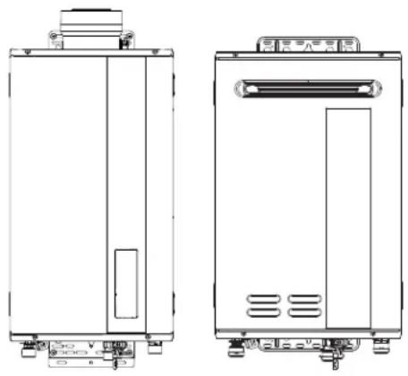
natural_image
Technical line drawings of two rectangular electronic devices with mounting brackets and ventilation slots (no text or symbols)





WARNING:
If the information in these instructions is not followed exactly, a fire or explosion may result, causing death, personal injury, or property damage.
⚠ For Your Safety!
- Do not store or use gasoline or other flammable vapors and liquids in the vicinity of this or any other appliance. To do so may result in an explosion or fire.
- Installation and service must be performed by a qualified installer, service agency, or the gas supplier.
What to Do If You Smell Gas
- Do not try to light any appliance.
- Do not touch any electrical switch; do not use any phone in your building.
- Immediately call your gas supplier from a neighbor's phone. Follow the gas supplier's instructions.
- If you cannot reach your gas supplier, call the fire department.
- Do not return to your home until authorized by the gas supplier or fire department.
Do not destroy manual. Please read carefully and keep in a safe place for future reference.
CONTENTS
Important Safety Information
Safety Precautions 2 - 8
Product Information
Product Information......8
Specifications.... 9, 10
Flow Rate vs Pressure Drop RTGH-Series-3....11
General Descriptions....12, 13
Installation Instructions
Standards Compliance....15
Choosing a Location 15, 16
Product Inspection.... 17
Water Heater Installation....17 - 20
Venting and High-Altitude Adjustments 21 - 34
Water Quality/Supply 35 - 39
Gas Supply....39 - 44
Electrical Wiring....45
Remote Control Selection and Location....46
Remote Control Installation 47
WiFi Remote Installation 48, 49
Insulation Blankets and Installation Precautions ....50
Installation Checklist....51
Using Your Water Heater
Activating the Water Heater ....52
Operating Instructions 53
Setting the Water Temperature 54 - 58
WiFi Set-up....58
Piping for Space Heaters 59
Recirculation Pump Control 60 - 63
Water Saving Control Option 64, 65
Caring for Your Water Heater
Water Heater Inspections.... 66, 67
Care and Cleaning....68, 69
Preventive Maintenance 70
Draining the Water Heater....71-72
Freeze Protection 73
Vacation and Extended Shutdown 74
Troubleshooting Chart.... 74, 75
Service Error Code Chart 76, 77
Call for Assistance 77
Maintenance Notice Option....78, 79
If You Need Service
Parts Ordering 80, 81
Warranty Information....82, 83
IMPORTANT SAFETY INFORMATION
READ THE SAFETY INFORMATION
Your safety and the safety of others are very important. There are many important safety messages in this manual and on your appliance. Always read and obey all safety messages.

This is the safety alert symbol. Recognize this symbol as an indication of Important Safety Information! This symbol alerts you to potential hazards that can kill or hurt you and others.
All safety messages will follow the safety alert symbol and either the word “DANGER,” “WARNING,” “CAUTION,” or “NOTICE.”
These words mean:
DANGER:
An imminently hazardous situation that will result in death or serious injury.
WARNING:
A potentially hazardous situation that can result in death or serious injury and/or damage to property.
CAUTION:
A potentially hazardous situation that may result in minor or moderate injury.
NOTICE:
Attention is called to observe a specified procedure or maintain a specific condition.
⚠️ WARNINGS:
- Improper installation, adjustment, alteration, service, or maintenance can cause death, personal injury, or property damage. Follow the instructions in this manual.
READ ALL INSTRUCTIONS BEFORE USING.
Be sure to read and understand the entire Use and Care Manual before attempting to install or operate this water heater. It may save you time and money. Pay particular attention to the Safety Instructions. Failure to follow these warnings could result in death or serious bodily injury. Should you have problems understanding the instructions in this manual, or have any questions, STOP and get help from a qualified service technician or the local gas utility.
IMPORTANT SAFETY INFORMATION
Water Heater Venting Safety
⚠️ DANGER:
- Failure to install and properly vent the water heater to the outdoors as outlined in the "Venting" section of the Installation Instructions in this manual will result in death from fire, explosion, or asphyxiation from carbon monoxide. NEVER operate this water heater unless it is properly vented and has an adequate air supply for proper operation.
- Be sure to inspect the vent terminal, the air intake, and the coaxial vent system on the water heater for proper installation at initial start-up and at least annually thereafter. Refer to the “Care and Cleaning” section of this manual for more information regarding coaxial vent system inspection.
⚠️ WARNINGS:
- Gasoline and other flammable liquids, materials, and vapors (including paint thinners, solvents, and adhesives) are extremely dangerous. DO NOT handle, use, or store gasoline or other flammable or combustible materials anywhere in the vicinity of a water heater or any other appliance. Be sure to read and follow the labels on the water heater, as well as the warnings printed in this manual. Failure to do so can result in death, bodily injury, or property damage.
- Combustible construction refers to adjacent walls and ceilings and should not be confused with combustible or flammable products and materials. Combustible materials, such as clothing, cleaning materials, or flammable liquids, should never be stored in the vicinity of this or any gas appliance. Fire or explosion can occur causing death, personal injury, and/or product damage. See page 16 for clearances to combustible materials.
- Follow vent manufacturer's instructions for venting installation, including additional clearances from combustibles, to avoid conditions that can lead to death, personal injury, and/or property damage.
- Use tankless water heater manufacturer-approved Category III Stainless Steel vent material only. No other vent material is permitted.
- Moisture in the flue gas will condense as it leaves the vent terminal. In cold weather this condensate can freeze on the exterior wall, under the eaves, and on surrounding objects. Some discoloration to the exterior of the building is to be expected. However, improper location or installation can result in severe damage to the structure or exterior finish of the building.
▲ DANGER

⚠ Vapors from flammable liquids will explode and catch fire causing death or severe burns.
Do not use or store flammable products such as gasoline, solvents or adhesives in the same room or area near the water heater.
Keep flammable products: 1. far away from heater,
2. in approved containers,
3. tightly closed and
4. out of children's reach.
Water heater has a main burner flame.
The main burner flame:
-
which can come on at any time and
-
will ignite flammable vapors.
Vapors:
-
cannot be seen,
-
are heavier than air,
-
go a long way on the floor and
-
can be carried from other rooms to the main burner flame by air currents.
Installation:
Do not install water heater where flammable products will be stored or used unless the main burner flame is at least
18" above the floor. This will reduce, but not eliminate, the risk of vapors being ignited by the main burner flame.
Read and follow water heater warnings and instructions. If owners manual is missing, contact the retailer or manufacturer.
- For multiple-unit installation, a minimum distance between vent terminations must be maintained to prevent recirculation of vent gases. Maintain a center-to-center distance between vent terminations of 19 in. (48 cm) for two-unit installation. Maintain a center-to-center distance between vent terminations of 21 in. (53 cm) for installation of three or more units.
CAUTIONS:
- Ensure that the appliance vent is securely attached to the water heater collar.
- Condensate must drain away from the water heater and should not be allowed to drain back into any part of the vent system.
- DO NOT operate without the condensate trap connected to the vent and routed to the proper drain.
- Follow the vent manufacturer's installation instructions because the design might vary from manufacturer to manufacturer.
IMPORTANT SAFETY INFORMATION
Water Supply Safety
DANGERS:
- WATER TEMPERATURE SETTINGS – Safety and energy conservation are factors to be considered when selecting the water temperature setting of a water heater's remote control. Water temperatures above 125°F (52°C) can cause death or severe burns from scalding. Be sure to read and follow the warnings outlined on the pictured label.
- There is a hot water scald potential if the water temperature is set too high. Households with small children, the disabled, or elderly persons may require a 120°F (49°C) or lower temperature setting to prevent contact with "HOT" water.
- Before manually operating the relief valve, make certain no one will be exposed to the danger of the hot water released by the valve. The water may be hot enough to create a scald hazard. The water should be released into a suitable drain to prevent injury or property damage.
- Failure to perform the recommended Routine Preventive Maintenance can harm the proper operation of this water heater, which can cause carbon monoxide dangers, excessive hot water temperatures, and other potentially hazardous conditions.
⚠️ WARNINGS:
- IMPORTANT: DO NOT apply heat to the HOT or COLD water connections. If sweat connections are used, sweat tubing to adapter before fitting adapter to the water connections on heater. Any heat applied to the water supply fittings will permanently damage the internal components of the water heater.
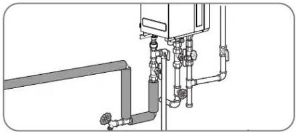
- In case the pipe insulation is not rated for the appropriate weather conditions, install electric heat tracing or equivalent to prevent freezing of the pipes. DO NOT insulate or block the drain valve on the hot outlet fitting. If the pipes are allowed to freeze, the water heater and the pipes may malfunction or leak due to freezing water.
- Failure to drain the water heater as described on Draining the Water Heater can cause serious personal injuries from scalding and/or damage the water heater.

Water temperature over 125^ F ( 52^ C) can cause severe burns instantly or death from scalds.
Children, disabled and elderly are at highest risk of being scalded.
See instruction manual before setting temperature at water heater.
Feel water before bathing or showering.
Temperature limiting valves are available, see manual.
CAUTIONS:
- This water heater must only be used with the following water supply system conditions:
- With clean, potable water free of corrosive chemicals, sand, dirt, or other contaminants.
- With inlet water temperatures above 32°F (0°C), but not exceeding 120°F (49°C).
- DO NOT reverse the hot and cold water connections. The water heater will not operate.
- Even when drained properly, a small amount of water will remain in the water heater. In cold weather conditions, this water can freeze. If this happens, allow the defrost protection on the heater at least 30 minutes to melt the frozen water or the water heater may not work properly.
Time/Temperature Relationship in Scalds
| Water Temperature | Time to Produce a Serious Burn |
| 120°F (49°C) | More than 5 minutes |
| 125°F (52°C) | 1 1/2 to 2 minutes |
| 130°F (54°C) | About 30 seconds |
| 135°F (57°C) | About 10 seconds |
| 140°F (60°C) | Less than 5 seconds |
| 145°F (63°C) | Less than 3 seconds |
| 150°F (66°C) | About 1 1/2 seconds |
| 155°F (68°C) | About 1 second |
Table courtesy of Shriners Burn Institute
| Temperature Conversion Chart °F/°C | |||||||
| 100 | 102 | 104 | 106 | 108 | 110 | 112 | °F |
| 38 | 39 | 40 | 41 | 42 | 43 | 44 | °C |
| 114 | 116 | 118 | 120 | 125 | 130 | 140 | °F |
| 46 | 47 | 48 | 49 | 52 | 54 | 60 | °C |
IMPORTANT SAFETY INFORMATION
Natural Gas and Liquefied Petroleum Safety
DANGERS:
- Never attempt to convert the water heater from one gas type to another. The water heater should only use the fuel type in accordance with listing on data plate—natural gas for natural gas units and LP for LP units. Any other fuel usage will result in death or serious personal injury from fire and/or explosion. This water heater is not certified for any other fuel type.
- Both natural gas and propane (LP) have an odorant added to aid in detecting a gas leak. Some people may not physically be able to smell or recognize this odorant. If you are unsure or unfamiliar with the smell of natural gas or LP, ask the gas supplier. Other conditions, such as “odorant fade,” which causes the odorant to diminish in intensity, can also hide or camouflage a gas leak.
- Water heaters using LP gas are different from natural gas models. A natural gas water heater will not function safely on LP and vice versa.
- LP water heaters should not be installed below grade (for example, in a basement) if such installation is prohibited by federal, state, and/or local laws, rules, regulations, or customs.
- LP must be used with great caution. It is heavier than air and will collect first in lower areas, making it hard to detect at nose level.
- Before attempting to light the water heater, make sure to look and smell for gas leaks. Use a soapy solution to check all gas fittings and connections. Bubbling at a connection indicates a leak that must be corrected. When smelling to detect a gas leak, be sure to also sniff near the floor.
- Gas detectors are recommended in LP and natural gas applications and their installation should be in accordance with the detector manufacturer's recommendations and/or local laws, rules, regulations, or customs.
- Combustible materials, such as clothing, cleaning materials, or flammable liquids, must not be placed in the vicinity of the water heater.
- If a gas leak is present or suspected:
- DO NOT attempt to find the cause yourself.
- Never use an open flame to test for gas leaks. The gas can ignite resulting in death, personal injury, or property damage.
- Follow the steps listed under "What to Do If You Smell Gas" found on the front cover of this manual.
⚠️WARNINGS:
- The installation of gas piping must conform to local utility company requirements and/or in the absence of local codes, use the latest edition of National Fuel Gas Code (NFGC), ANSI Z223.1/NFPA 54, or CAN/CSA B149.1, Natural Gas and Propane Installation Code.
- If inlet gas pressure is out of allowable range [4.0" w.c. (1.0kPa) – 10.5" w.c. (2.6kPa)] for Natural Gas, or [8.0" w.c. (2.0kPa) – 13.0" w.c. (3.2kPa)] for LP gas, a gas pressure regulator must be installed to maintain the allowable inlet gas pressure.
- Should overheating occur or the gas supply fail to shut off, turn off the manual gas control valve to the water heater.
CAUTIONS:
- DO NOT attempt repair of electrical wiring, gas piping, remote control, burners, vent connectors, or other safety devices. Refer repairs to qualified service personnel.
- Turn off the manual gas shut-off valve if the water heater has been subjected to overheating, fire, flood, physical damage, or if the gas supply fails to shut off.
- DO NOT turn on the water heater unless the water and gas supplies are completely opened.
NOTICE:
- The factory setting allows operating temperatures between 100°F (38°C) and 120°F (49°C). Only qualified service personnel should perform this adjustment. Only factory-authorized remote control(s) should be used.
IMPORTANT SAFETY INFORMATION
Before operating this water heater, be sure to read and follow the instructions on the label pictured below and all other labels on the water heater, as well as the warnings printed in this manual. Failure to do so can result in unsafe operation of the water heater, resulting in death, personal injury, or property damage. Should you have any problems reading or following the instructions in this manual, STOP and get help from a qualified service technician.
WARNING : If you do not follow these instructions exactly, a fire or explosion may result causing property damage, personal injury or loss of life.
A. This appliance does not have a pilot. It is equipped with an ignition device which automatically lights the burner. Do not try to light the burner by hand.
B.BEFORE OPERATING smell all around the appliance area for gas. Be sure to smell next to the floor because some gas is heavier than air and will settle on the floor. WHAT TO DO IF YOU SMELL GAS
- Do not try to light any appliance. -Do not touch any electric switch; do not use any phone in your building. -Immediately call your gas supplier from a neighbor's phone. Follow the gas supplier's instructions. -If you cannot reach your gas supplier, call the fire department.
●Do not return to your home until authorized by the gas supplier or fire department.
C. Use only your hand to push in or turn the gas control knob. Never use tools. If the knob will not push in or turn by hand, don't try to repair it, call a qualified service technician. Force or attempted repair may result in a fire or explosion.
D.Do not use this appliance if any part has been under water. Immediately call a qualified service technician to inspect the appliance and to replace any part of the control system and any gas control which has been under water.
OPERATING INSTRUCTIONS
1.STOP! Read the safety information above on this label.
2. Turn off all electric power to the appliance.
3. Do not attempt to light the burner by hand.
4. Turn the Gas Shutoff Valve located on the outside of the unit clockwise to the "OFF" position.
5. Wait five (5) minutes to clear out any gas. If you then smell gas, STOP! Follow "B" in the safety information above on this label. If you don't smell gas, go to the next step.
6. Turn the Gas Shutoff Valve located on the outside of the unit counterclockwise ∩ to the "ON" position.
7. Turn on all electric power to the appliance.
8. If the appliance will not operate, follow the instructions "To Turn Off Gas To Appliance" and call your service technician or gas supplier.
TO TURN OFF GAS TO APPLIANCE
- Turn off all electric power to the appliance if service is to be performed.
- Turn the Gas Shutoff Valve located on the outside of the unit clockwise to the "OFF" position.

OPEN CLOSE

IMPORTANT SAFETY INFORMATION
Electrical Safety
DANGER:
- Shock Hazard – Make sure the electrical power to the water heater is off to avoid electric shock that will result in death or serious personal injury.
⚠️ WARNINGS:
- For your safety, the information in this manual must be followed to minimize the risk of fire, explosion, or electric shock that can result in death, personal injury, and/or property damage.
- Field wiring connections and electrical grounding must comply with local codes or, in the absence of local codes, with the latest edition of the National Electrical Code, ANSI/NFPA 70, or in Canada, Canadian Electrical Code, CAN/CSA C22.1, Part 1.
CAUTIONS:
- Label all wires prior to disconnecting for service. Wiring errors can cause dangerous and improper operation. Verify correct operation after servicing.
- For your safety, burner inspection and cleaning should be performed only by qualified service personnel.
- Make certain the power to the water heater is OFF before removing the unit cover panel. Exposed electrical components and moving parts can cause personal injuries.
- For your safety, DO NOT attempt repair of electrical wiring, gas piping, remote control, burners, vent connectors, or other safety devices. Refer repairs to qualified service personnel.
FOR INSTALLATIONS IN THE STATE OF CALIFORNIA
California law requires that water heaters must be braced, anchored, or strapped to resist falling or horizontal displacement due to earthquake motions. For water heaters up to 52-gallon capacity, a brochure with generic earthquake bracing instructions can be obtained from: Office of the State Architect, 1102 Q Street, Suite 5100, Sacramento, CA 95814, or you may call 916-445-8100 or ask a water heater dealer.
However, applicable local codes shall govern installation. For residential water heaters of a capacity greater than 52 gallons or tankless-style, consult the local building jurisdiction code for acceptable bracing procedures.
IMPORTANT SAFETY INFORMATION
General Installation and Maintenance Safety
⚠️WARNINGS:
- This water heater must be installed in accordance with these instructions, local codes, utility company requirements and/or in the absence of local codes, use the latest edition of the American National Standard/National Fuel Gas Code (NFGC), ANSI Z223.1 and National Fire Protection Association, NFPA 54, or in Canada, CAN/CSA B149.1, Natural Gas and Propane Installation Code, and the latest edition of the National Electrical Code, ANSI/NFPA 70, or in Canada, Canadian Electrical Code, CAN/CSA C22.1, Part 1.
- If local codes require the application of external insulation blanket kits, carefully follow the manufacturer's installation instructions included with the kit. Only use blanket kits that are approved for use with your water heater.
- For your safety, DO NOT attempt to disassemble this water heater for any reason. Improper adjustments, alterations, service, or maintenance can cause death, personal injury, or property damage.
SAFETY PRECAUTIONS:
- Read this manual entirely before installing and/or operating the water heater.
- Use this water heater only for its intended purpose as described in this Use and Care Manual.
- Have the installer show you the location of the gas shut-off valve and how to shut it off if necessary. Turn off the manual shut-off valve if the water heater has been subjected to overheating, fire, flood, physical damage, or if the gas supply fails to shut off.
- Be sure your water heater is properly installed in accordance with local codes and the provided installation instructions.
- DO NOT attempt to repair or replace any part of your water heater unless it is specifically recommended in this manual. All other servicing should be referred to a qualified service technician.
SAVE THESE INSTRUCTIONS
PRODUCT INFORMATION
For Your Records
Write down and save the following product information along with the original sales slip and/or cancelled check. The model and serial numbers can be found on the top label on the right side of the water heater.
MODEL NUMBER:
SERIAL NUMBER:
DATE OF INSTALLATION:
INSTALLING COMPANY/PHONE NUMBER:
PLUMBING CONTRACTOR/PHONE NUMBER:
See page 77 for additional service information.
Read This Manual
Inside you will find many helpful hints on how to use and maintain your water heater properly. A little preventive care on your part can save you time and money over the life of your water heater.
You'll find many answers to common problems in the Troubleshooting Chart in this Use and Care Manual. Always refer to this chart before calling for service. Referring to this chart before calling may answer your question(s) and eliminate the need for service.
Preoperating Checklist
Is the main gas valve to the water heater turned on?
☐ Is the fuse in place or is the breaker turned on?
Does the water heater's electronic ignition light?
Is the water temperature set to a safe temperature?
☐ Is the water heater connected to a floor drain?
Is the water heater properly vented to the outside?
☐ Is the water heater installed in a safe location away from flammable materials and/or freezing conditions?
PRODUCT INFORMATION
Specifications – Direct-Vent Models

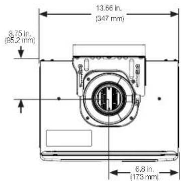

Specifications – Outdoor Models


PRODUCT INFORMATION
Specifications
The following product information can be found from the rating label on this water heater:
A Model Number
B Serial Number
C Data Bar Code
D Heater Type
E Installation Type
F Type of Gas
G Max Inlet Gas Pressure
H Min Inlet Gas Pressure
J Recovery Rating
K Max BTU Input Rating
L Min BTU Input Rating
M Manifold Gas Pressure
N Certification Stamp
P Alternate Approval Stamp
Q Clearances
Rating Label

This appliance must be installed in accordance with local codes or, in the absence of local codes, the National Fuel Gas Code, ANS1Z223.1/NFPA S4 or the CSA B149.1, Natural Gas and Propane Installation Code.
"Suitable for water(potable) heating and space heating." "The water heater shall not be respected to any heating system or component(s) previously used.
with a nonpotable water heating appliance" "A pressure relief valve listed a
complying with the Standard for Reel-Valves and Automatic Gas-Shuton Devices for Hot Water Supply Systems, ANSI Z21.22 shall be installed at the
hot water outlet connection of the water heater at the time of installation of the heater. Local codes shall govern the installation of relief devices.
For safe operation of the water heater, the relief valve(s) must not be
removed or plugged. No valve shall be placed between the relief valve and the water heater. The relief from the discharge of the pressure relief valve.
shall be disposed of in a suitable place where it will cause no damage. Also there shall be no other reducing coupling or other restrictions installed on
the discharge line to restrict flow. See Installation Manual Heading,
PRESSURE REEER VALVES for installation and maintenance of relief valve discharge line and other safety precautions. Turn off the electrical power
and gas shutoff valve. Lift and release lever on the relief valve and check the manual operation of relief valve at least once a year. "Make certain
the discharged water is directed to a suitable drain. Avoid contact with hot water and prevent water damage.
"MINIMUM CLEARANCE FROM COMBUSTIBLE OR NONCOMBUSTIBLE CONSTRUCTION: 1/2" SIDE
CLEARANCE FROM FLANGED ENDS TO WALL, 0" REAR CLEARANCE-FROM MOUNTING BRACKET TO WALL: 12" TOP CLEARANCE-FROM TOR OF HEATER TO CEILING-12" BOTTOM
CLEARANCE-FROM BOTTOM OF HEATER 1D FLOOR; 12" FRONT CLEARANCE-FROM FRONT OF HEATER TO CLOSET DOORS. WHITE: FLAMTHIA RECOMMENDED FRONT CLEARANCE FOR
- HEATER TO CLOSET DOOR "NOTE 24 MINIMUM RECOMMENDED FRONT COVER"
- SERVICE AND MAINTENANCE." WIRING DIAGRAM BEHIND THE FRONT COVER."
FOR YOUR SAFETY: DO NOT STORE OR USE GASOLINE OR OTHER
FLAMMABLE VAPORS AND LIQUIDS IN THE VICINITY OF THIS OR ANY OTHER APPLIANCE

Indoor Outdoor

natural_image
Technical line drawing of an open industrial machine with internal components and a black arrow indicating a specific part (no text or symbols present)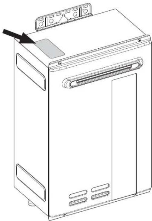
natural_image
Line drawing of a front-loading washing machine with a door and control panel (no text or symbols)PRODUCT INFORMATION
The graphic below illustrates the pressure drop across the water heater. Please ensure ample water supply pressure is available to ensure the best performance.


PRODUCT INFORMATION
General Descriptions
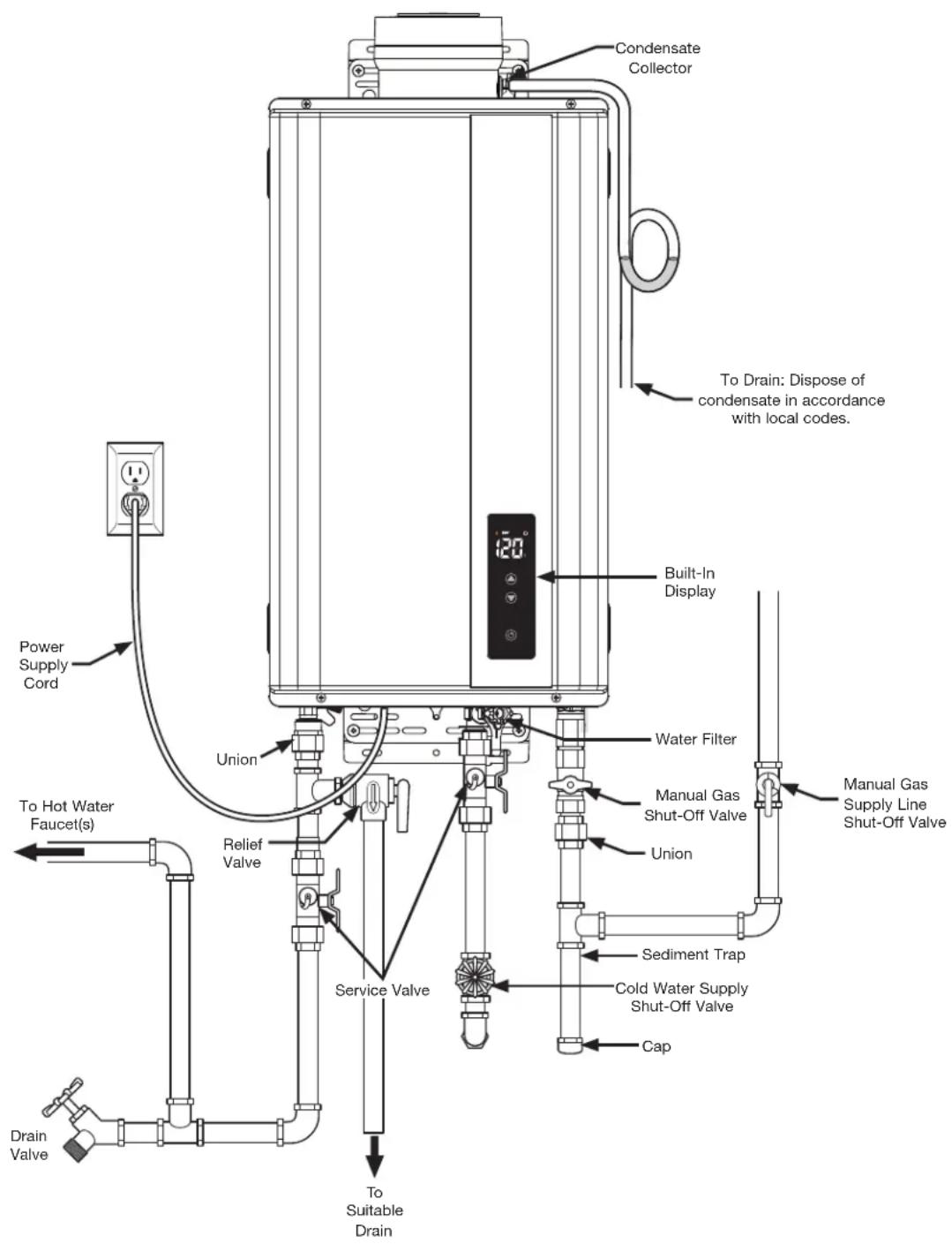
Typical Direct-Vent Water Heater (Venting Required)
PRODUCT INFORMATION
Typical Outdoor Water Heater (No Venting Required)
This water heater is for OUTDOOR installation only.
DANGER:
DO NOT install this water heater indoors or in a confined area. It is designed for outdoor installation only. Any other type of installation will result in death or serious personal injury.

INSTALLATION INSTRUCTIONS
FOR THE CONTRACTOR
INSTALLATION INSTRUCTIONS

Standards Compliance
This water heater must be installed in accordance with these instructions, local codes, and utility company requirements.
In the United States where local codes are not available, use the latest edition of the American National Standard/National Fuel Gas Code. A copy of the Fuel Gas Code can be purchased from either the American Gas Association, 400 North Capitol Street Northwest, Washington, DC
20001, as ANSI standard Z223.1, or National Fire Protection Association, 1 Batterymarch Park, MA 02269 as NFPA 54.
In Canada, use the latest edition of the CAN/CSA B149.1 Natural Gas and Propane Installation Code and the Canadian Electrical Code, CAN/CSA C22.1, Part 1.

Choosing a Location
AWARNING:
Fire Hazard – Combustible construction refers to adjacent walls and ceilings and should not be confused with combustible or flammable products and materials. Combustible materials, such as clothing, cleaning materials, or flammable liquids, must not be placed against or next to the water heater. Fire or explosion could occur causing death, personal injury, and/or product damage. A gas-fired water heater should never be installed in a space or room where liquids with flammable vapors are used or stored. Such liquids include gasoline, LP gas (butane or propane), paint, adhesives and their thinners, solvents, or removers. Flammable vapors carry long distances from where they are used or stored. The open flame of the water heater's main burner can ignite these vapors causing an explosion or fire.
NOTICE:
Elevating a gas-fired water heater will reduce but NOT eliminate the possibility of lighting the vapor of flammable liquids which may be improperly stored or accidentally spilled.
NOTICE:
DO NOT connect power until venting installation is complete. See "Venting."
NOTICE:
This water heater should not be located in an area where leakage of the heat exchanger or connections will result in damage to the area adjacent to it or to lower floors of the structures. When such areas cannot be avoided, install a suitable catch pan with an adequate drain under the water heater. This drain pan must not restrict the combustion airflow.
The following requirements will ensure a safe installation:
The water heater must be located in an area where it won't sustain damage from moving vehicles, flooding, etc. If the water heater is installed in a storage garage, the direct ignition system and main burner should be no less than 18 in. (45 cm) above the garage floor.
If the water heater is installed in a repair garage or in a private garage, the direct ignition system and main burner should be no less than 4.5 ft. (1400 mm) above the garage floor.
The water heater should be installed as close as possible to the vent termination. This minimizes the vent length and the number of elbows and joints required for venting.
The water heater should be installed with the proper venting and exhaust materials suitable for Category III venting.
INSTALLATION INSTRUCTIONS

Choosing a Location

Every vent pipe penetration of a floor or ceiling that is not in a fire-rated shaft requires a fire stop plate.
Failure to install and properly vent the water heater to the outdoors as outlined on "Venting" can result in unsafe operation.
natural_image
Pure technical diagram of piping and valves without any text, numbers, or symbolsLong hot water lines should be insulated to conserve water and energy.
The water heater and water lines should be protected from exposure to freezing temperatures.

- DO NOT install the water heater in areas prohibited by National Fuel Gas Code in U.S. installation or CAN/CSA B149.1 in Canada installation.
- DO NOT install the water heater where it is subject to vibrations.

- DO NOT install the water heater in a recreational vehicle, boat, or other watercraft.

- DO NOT install the water heater near vents for heating and cooling. If necessary, maintain a minimum clearance of 4 ft. (1.2 m).
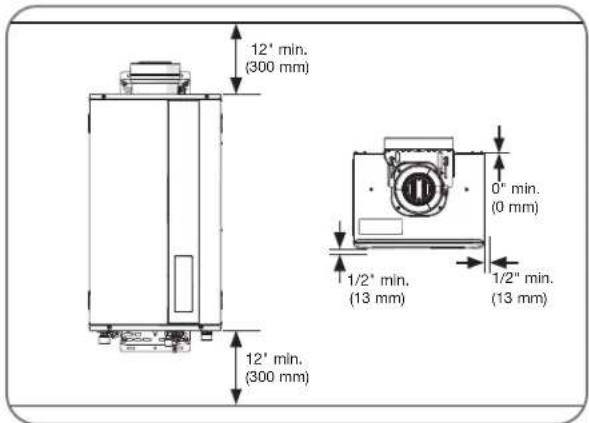
Minimum water heater clearances from combustible and noncombustible construction are as follows:
- 1/2 in. (1.3 cm) for sides and front
- 0 in. (0 cm) for rear with support bracket(s)
- 12 in. (30 cm) from the bottom and top
NOTICE:
Preferred maintenance clearance is 24 in. (61 cm) from top, bottom, and front of unit.
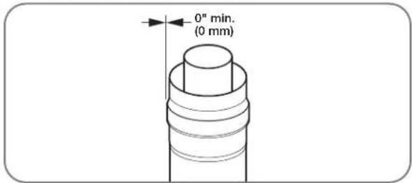
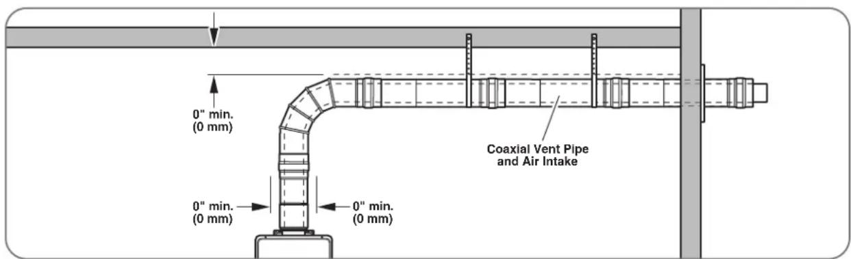
Minimum clearance around the coaxial vent pipe should meet the specifications listed on the instruction/warning label on the water heater. If no label is found, use the vent manufacturer's specifications or a minimum clearance of 0 in. (0 cm) around the vent pipe.
INSTALLATION INSTRUCTIONS

Product Inspection
Visually inspect the water heater for any possible damage.
Check the rating plate on the water heater to make sure the water heater was designed to be used
with the supplied type of gas (natural or LP).
Verify that all included supplied parts are present as shown.

WiFi Display / Wall Mount (outdoor models only)

natural_image
Illustration of multiple screws with three screw holes (no text or symbols)Screws

Washers

natural_image
Technical line drawing of two metal bracket components with mounting holes and mounting holes (no text or symbols)Mounting Stays

natural_image
Line drawing of a coiled cable or tube with two connectors (no text or symbols)Remote Control Cable

natural_image
Line drawing of a handheld device with a curved arrow indicating rotation or force (no text or symbols)Pressure Relief Valve (Some models only)

Water Heater Installation
Corrosive Atmosphere
NOTICE:
The water heater should not be installed near an air supply containing halogenated hydrocarbons.
Avoid installing a water heater in any of the following locations: beauty shops, dry-cleaning establishments, photo processing labs, and storage areas for liquid and powdered bleaches or swimming pool chemicals. These locations often contain such halogenated hydrocarbons. The air supply containing halogenated hydrocarbons is safe to breathe, but when passed through a gas flame,
corrosive elements are released that will shorten the life of any gas-burning appliance.
Propellants from common spray cans or gas leaks from A/C and refrigeration equipment are highly corrosive after passing through a flame.
NOTICE:
The water heater warranty is void when the failure is due to operation in corrosive conditions.
INSTALLATION INSTRUCTIONS

Water Heater Installation
NOTICE:
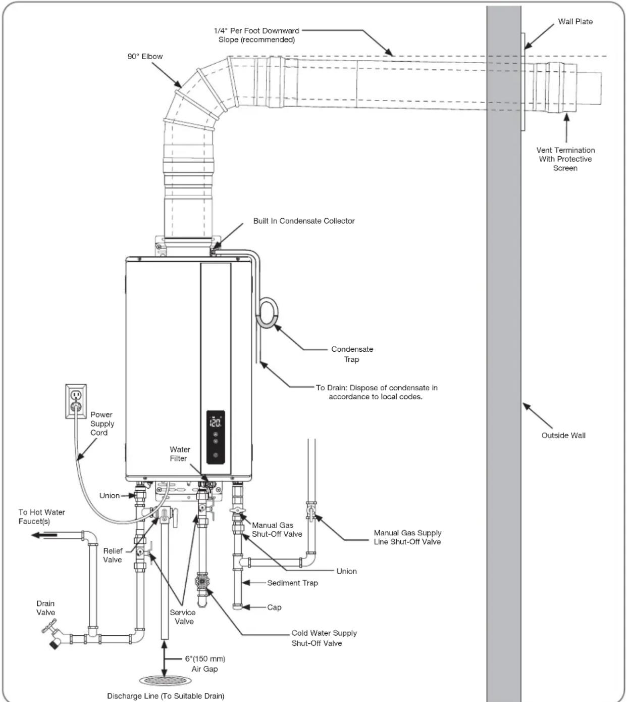
The National Fuel Gas Code (NFGC) and CAN/CSA B149.1 mandate a manual gas shut-off valve. See NFGC/B149.1 for complete instructions. Local codes or plumbing authority requirements may vary from the instructions or diagrams provided and take precedence over these instructions.
Typical Installation of Direct-Vent Water Heater (Venting Required)
INSTALLATION INSTRUCTIONS

Water Heater Installation
Typical Installation of Outdoor Water Heater (No Venting Required)
This water heater is for OUTDOOR installation only.
WARNING:
DO NOT install this water heater indoors or in a confined area. It is designed for outdoor installation only. Any other type of installation can result in death, personal injury, and/or damage to the product or property.

Alternate Water Piping Arrangement With Preferred Valve Kit
A valve kit is available and can be used with all models. See "Water Supply Connections" on page 35 for installation instructions.

INSTALLATION INSTRUCTIONS
Mounting the Water Heater
CAUTION
Reinforcement of the wall is required in case the wall is not strong enough to hold the water heater. Failure to do so could result in personal injury and/or product or property damage.
The mounting location for the water heater should allow for easy access and operation.

natural_image
Technical line drawing of two window frame structures with vertical supports and horizontal bars, no text or symbols presentThe water heater is designed to be installed either inside the wall cavity, between the wall studs, or outside the wall cavity. Either installation requires the water heater to be supported with a wooden support brace between the wall studs or a piece of wood that is equal in size to the water heater and securely attached to the wall studs before the water heater is attached to it. This piece of wood can be installed inside or outside the wall. Use wood screws to secure brackets to the wall. If mounting to a concrete wall, use lag bolts designed for concrete.
natural_image
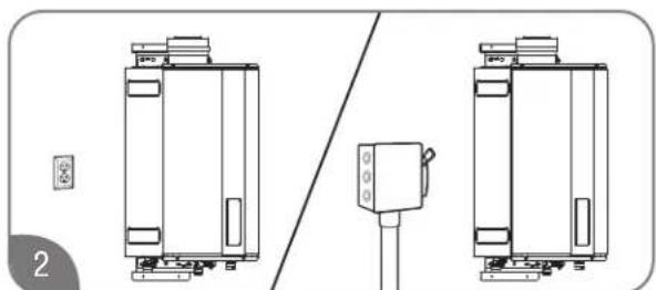
Technical line drawing of two identical mechanical or electrical components with a central control unit (no text or symbols)Make sure the proper electrical outlet or supply (120 VAC/60 Hz) is available and located near the unit. Direct-vent models come with a 6-ft. (1.8-m) power cord, while the outdoor models require hard-wiring or the addition of a plug.
natural_image
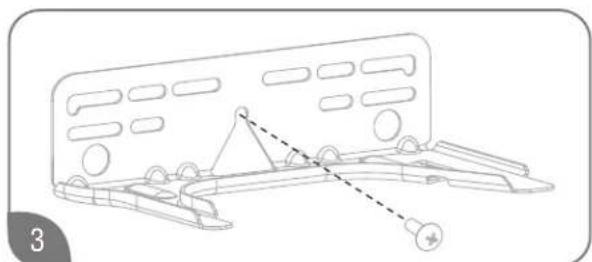
Technical line drawing of a mechanical assembly with no visible text or symbolsPosition the upper mounting bracket and partially install the center mounting screw. The clearance between the screw head and the wall should be about 1/8 in. (0.3 cm). Hang the upper bracket on the screw.
NOTICE:
The image above may differ in appearance from your water heater.

Using two mounting screws and washers, secure the lower mounting bracket to the wall. Then, secure the upper mounting bracket to the wall with two mounting screws and washers.

Position the water heater and tighten the adjustment screws to complete the installation. The rear of the water heater can be positioned anywhere between 3/8 in. (0.95 cm) and 1 1/2 in. (3.8 cm) from the wall (indoor model only).

natural_image
Technical line drawing showing mechanical assembly with components and alignment (no text or symbols)"If additional clearance is needed to the back wall in order to attach venting, utilize the mounting stays included with the heater. Attach the stays to the heater mounting brackets using the included screws, then follow the above steps to attach the heater to the wall. The mounting stays add 1 3/16in. (3cm) of clearance."
INSTALLATION INSTRUCTIONS

Venting for Direct-Vent Water Heater
The water heater must be installed with 3-in./5-in. (7.6-cm/12.7-cm) diameter UL-approved Category III Coaxial Stainless Steel appliance vent pipe or water heater manufacturer-approved concentric vent pipe.
DANGER:
Failure to install and properly vent the water heater to the outdoors as outlined in this Venting section will result in death or serious personal injury. To avoid the risk of fire, explosion, or asphyxiation from carbon monoxide, NEVER operate the water heater unless it is properly vented and has adequate air supply for proper operation as outlined in this Venting section.
⚠️ WARNINGS:
- Use 3-in./5-in. (7.6-cm/12.7-cm) UL-approved Category III Stainless Steel vent materials or water heater manufacturer-approved vent material. No other vent material is permitted for use with this appliance.
- Refer to page 16 for required clearances to combustible materials. Improper clearances can cause explosion or fire resulting in death, personal injury, and/or product damage.
Venting Requirements
The installation of venting must comply with national codes, local codes, and the vent manufacturer's instructions.
The water heater must be vented to the outdoors as described in these instructions. DO NOT vent this water heater through a chimney. It must be vented separately from all other appliances.
This water heater requires a special venting system. Refer to venting supplier's instruction for complete parts list and method of installation. The manufacturers and product lines listed on the following tables have been tested and authorized to safely operate with Rheem tankless water heater. Supplier of stainless steel venting that are not listed on the following table is not permitted for use Category III products with Rheem tankless water heater.
WARNING:
DO NOT mix venting suppliers and models in venting systems. Failure to comply could result in personal injury, property damage, or death
Installations must comply with applicable national, state, and local codes.
Allowable Stainless Steel Vent Supplier and Part Numbers
| Example of Components | Metal Fab |
| Pipe *3CGVxx, 3CGxx | |
| 90 Degree Elbow 3CGV90L | 3CG90L |
| 45 Degree Elbow 3CGV45L | 3CG45L |
| Adjustable Vent Length 3GV | VL22, 3CGVVAL20 |
| Vertical Cap Termination 3CGVPVT, 3CGPVT | |
| Appliance Adapter 3CGVVPA, 3CGVPA | |
| Condensate Drain 3CGVVDS, 3CGVDS | |
| Horizontal Termination | 3CGVPHT, 3CGPHT,3CGVPHT3, 3CGVPHT4 |
*: xx refer to length of pipe
CAUTION:
DO NOT attempt to fabricate or adapt other vent pipe or materials to this venting.
Use the provided screws to connect the coaxial vent pipe together.
Follow the vent manufacturer's installation instructions.
This water heater can be vented horizontally or vertically. All coaxial vent piping runs must be adequately supported. The maximum recommended unsupported span should be no more than 4 ft. (1.2 m). Only use support isolation hanging bands. DO NOT use wire to support pipe runs.
Preexisting Venting Notes:
If the water heater is being installed as a replacement for an existing water heater, a thorough inspection of the existing venting and air intake system must be performed prior to any installation work. Verify that the correct materials, vent lengths, and terminal locations as described in this manual have been met. Carefully inspect the entire venting and air intake system for any signs of cracks or fractures, particularly at the joints between elbows or other fittings and the straight runs of vent pipe. Check the system for signs of sagging or other stresses in the joints as a result of misalignment of any components in the system. If any of these conditions are found, they must be corrected in accordance with the venting instructions in this manual before completing the installation and putting the water heater into service.
See page 26 for additional requirements for the Commonwealth of Massachusetts.
INSTALLATION INSTRUCTIONS

Venting for Direct-Vent Water Heater
Vent Lengths
Before starting the vent installation, careful planning should be given to the routing and termination of the vent pipes. The length of the vent pipes (inlet and outlet) should be kept to a minimum. Also, see pages 27,28, and 29 for vent terminal placement. Refer to the maximum and minimum vent length charts for the pipe sizes that can be used and the total equivalent length of pipe that can be used. DO NOT exceed equivalent length of pipe in maximum vent length chart.
DO NOT USE Schedule 20, Cell Core, Drain Pipe, Galvanized, Aluminum or B-Vent.
| SINGLE UNIT: MAX. EQUIVALENT VENT LENGTHS - STRAIGHT PIPE | |
| Number of 90° ELbows | Max Length 3"/5" Straight Pipe |
| 0 43 ft. (13.1 m) | |
| 1 41.5 ft. (12.6 m) | |
| 2 38.5 ft. (12.2 m) | |
| 3 34 ft. (11.7 m) | |
| 4 28 ft. (11.3 m) | |
| 5 20.5 ft. (10.8 m) | |
| 6 11.5 ft. (10.4 m) | |
| EQUIVALENT FT. OF ELBOWS | |
| 3" / 5" | |
| 90° 1.6 ft. | |
| 45° 9 in. | |
The vent termination is not included in the equivalency calculations.
NOTICE: A 90 degree standard bend concentric elbow is equivalent to 1 ft, 6 in. A 45 degree standard bend concentric elbow is equivalent to 9 in.
INSTALLATION INSTRUCTIONS

Venting for Direct-Vent Water Heater
High-Altitude DIP Switch Adjustments
When the water heater is installed above 2000 ft. (610 m), the settings on the DIP switch located on the control board need to be changed per vent length and altitude. If these settings are not changed, the water heater may not function properly.
| SECTION HIGH-ALTITUDE |
| Sea Level (A Setting) 0-2000 ft (0 m - 610 m) |
| B Setting 2001 ft - 5400 ft (610 m - 1650 m) |
| C Setting 5401 ft - 7800 ft (1650 m - 2377 m) |
natural_image
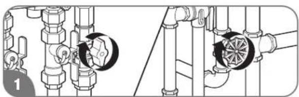
Technical diagram showing pipe fittings and valve assembly (no text or labels)Verify the altitude that the water heater is installed. Turn off the gas and water to the water heater by closing the shut-off valves.

natural_image
Technical line drawing of a mechanical component with mounting bracket and cylindrical top (no text or symbols)Remove the front cover panel on the water heater.

Find DIP Switch 2 located in the top-right portion of the control board. The switch labeled "DIP 2" is the bottom switch.

The factory settings for this switch should all be in the OFF position (DOWN).
NOTICE:
DO NOT alter any other DIP switch settings. The manifold pressure will be reduced accordingly.
For altitudes above 2000 ft. (610 m), refer to the table below for the necessary DIP switch settings. These setting must be changed to ensure proper operation.
| ALL VENT LENGTHS | ||||||
| Identify Vent Length | IDENTIFY ALTITUDE | |||||
| 0 - 2,000 ft | 2,001 - 5,400 ft | 5,400 - 7,800 ft | ||||
| Setting | Dip | Setting | Dip | Setting | Dip | |
| All Vent Lengths | A(Factory Setting) | B | C | |||

natural_image
Technical line drawing of a mechanical device interior showing internal components and housing (no text or symbols)Replace the front cover panel.

natural_image
Technical diagram showing pipe fittings and valve assembly (no text or labels)Turn on the gas and water to the water heater by opening the shut-off valves.
WARNING:
This water heater requires the correct DIP switch adjustments per vent length and altitude for proper operation. Incorrect DIP switch adjustments may cause improper water heater operation resulting in serious injury or death.
INSTALLATION INSTRUCTIONS

Venting for Direct-Vent Water Heater

NOTICE:
It is recommend to have a vent length as short as possible. Input rate at high altitude naturally is derated. In addition to that, input rate of the water heater decreases more if there is restriction (pressure drop) in the venting system. Refer to input rate reduction table due to vent length on page 24. Actual input rate reduction may be different at each installation.
NOTICE:
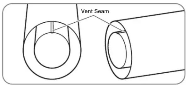
Make sure that the seam of the inner vent pipe in a horizontal run is towards the top of the installation as shown above.
Venting Through Closed Spaces
If the coaxial vent piping passes through a closed space, a minimum clearance of 0 in. (0 cm) for vertical piping and for horizontal piping should be maintained between the coaxial vent pipe and combustibles and non combustibles. Be sure to follow local codes and vent manufacturer's installation instructions.
For maintenance and inspection purposes, the following access panels may be required.
Two (2) inspection access panels large enough to allow access for venting inspection. One access panel may be close to where the coaxial vent pipe enters the ceiling. The other access panel may be near the vent termination.
It is recommend to have a vent length as short as possible. Input rate of the water heater decreases if there is restriction (pressure drop) in the venting system.
The following table shows approximate input rate reduction. Actual input rate reduction may be different at each installation.
This table will only apply to the indoor models.
| Setting Min | Vent Length Max | Vent Length |
| A-1 | 0% | 10% |
INSTALLATION INSTRUCTIONS

Venting for Direct-Vent Water Heater
Appliance Vent Adapter
CAUTION:
Ensure that the appliance vent adapter is securely attached to the water heater collar. Improperly connected vent adapter can cause damage to the appliance and/or poor performance.
Metal Fab Inc., Rainbow, and Ubbink standard concentric vent pipe can be installed into the water heater collar without an appliance vent adapter.
NOTICE:
To install the appliance vent adapter, please follow the appliance vent adapter manufacturer's instructions.
Draining Vent Condensate
⚠️WARNINGS:
Failure to provide a vent condensate drain close to the water heater could allow acidic flue gas condensate to enter into water heater flueways, causing premature failure of the water heater.
If the condensate collector is not used, the drain fitting must be capped to prevent exhaust gases and condensate from entering the building. The cap is supplied on the water heater.
CAUTIONS:
Condensate is known to be acidic; refer to federal, state (provincial), and local codes for proper handling and discharge methods.
Condensate must be drained away from the water heater and should not be allowed to drain back into any part of the vent system.
The condensate collector must be used with vertical vent installation.
Condensate collector must be used with horizontal vent installation if the vent has an UPWARD slope toward the termination.
Provision should be made to collect and dispose of condensate from the venting systems.

When a water heater is vented horizontally, the vent pipe should have a DOWNWARD or UPWARD slope towards the termination. If an UPWARD slope is used, always attach a drain hose to the condensate collector and plumb the hose to a sanitary sewer drain.

When a water heater is vented vertically, an UPWARD slope must always be used. Always attach a drain hose to the condensate collector and plumb the hose to a sanitary sewer drain.
Properly installed condensate traps prevent the condensate from draining back into the water heater.
A high-temperature silicone tubing suitable for use with acidic condensate and appropriate for the temperature range should be used.
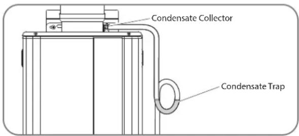
The drain tube is fashioned into a “pigtail” trap and must be filled with water to prevent flue gases from emitting into the building prior to operating the water heater.
INSTALLATION INSTRUCTIONS

Venting for Direct-Vent Water Heater
In the Commonwealth of Massachusetts
The Commonwealth of Massachusetts requires compliance with regulation 248 CMR 4.00 and 5.00 for installation of through-the-wall vented gas appliances as follows:
5.08: Modifications to NFPA-54, Chapter 10
(1) Revise NFPA-54 section 10.5.4.2 by adding a second exception as follows:
Existing chimneys shall be permitted to have their use continued when a gas conversion burner is installed, and shall be equipped with a manual reset device that will automatically shut off the gas to the burner in the event of a sustained backdraft.
(2) Revise 10.8.3 by adding the following additional requirements:
(a) For all side-wall, horizontally vented, gas-fueled equipment installed in every dwelling, building, or structure used in whole or part for residential purposes, including those owned or operated by the Commonwealth and where the side-wall exhaust vent termination is less than seven (7) feet above finished grade in the area of the venting, including but not limited to decks and porches, the following requirements shall be satisfied.
- INSTALLATION OF CARBON MONOXIDE DETECTORS. At the time of installation of the side-wall, horizontally vented, gas-fueled equipment, the installing plumber or gasfitter shall observe that a hard-wired carbon monoxide detector with an alarm and battery backup is installed on the floor level where the gas equipment is to be installed. In addition, the installing plumber or gasfitter shall observe that a battery-operated or hard-wired carbon monoxide detector with an alarm is installed on each additional level of the dwelling, building, or structure served by the side-wall, horizontally vented, gas-fueled equipment. It shall be the responsibility of the property owner to secure the services of qualified licensed professionals for the installation of hard-wired carbon monoxide detectors.
a. In the event that the side-wall, horizontally vented, gas-fueled equipment is installed in a crawl space or an attic, the hard-wired carbon monoxide detector with alarm and battery backup may be installed on the next adjacent floor level.
b. In the event that the requirements of this subdivision cannot be met at the time of completion of installation, the owner shall have a period of thirty (30) days to comply with the above requirements, provided, however, that during said thirty (30) day period, a battery-operated carbon monoxide detector with an alarm shall be installed.
-
APPROVED CARBON MONOXIDE DETECTORS. Each carbon monoxide detector as required in accordance with the above provisions shall comply with NFPA 720 and be ANSI/UL 2034-listed and IAS-certified.
-
SIGNAGE. A metal or plastic identification plate shall be permanently mounted to the exterior of the building at a minimum height of eight (8) feet above grade directly in line with the exhaust vent terminal for the horizontally vented, gas-fueled heating appliance or equipment. The sign shall read, in print size no less than one-half (1/2) inch in size, "GAS VENT DIRECTLY BELOW. KEEP CLEAR OF ALL OBSTRUCTIONS."
-
INSPECTION. The state or local gas inspector of the sidewall, horizontally vented, gas-fueled equipment shall not approve the installation unless, upon inspection, the inspector observes carbon monoxide detectors and signage installed in accordance with the provisions of 248 CMR 5.08 (2)(a)(1 through 4).
(b) EXEMPTIONS: The following equipment is exempt from 248 CMR 5.08 (2)(a)(1 through 4): -
The equipment listed in Chapter 10 entitled "Equipment Not Required To Be Vented" in the most current edition of NFPA 54 as adopted by the Board, and
-
Product-approved side-wall, horizontally vented, gas-fueled equipment installed in a room or structure separate from the dwelling, building, or structure used in whole or in part for residential purposes.
(c) MANUFACTURER REQUIREMENTS – GAS EQUIPMENT VENTING SYSTEM PROVIDED. When the manufacturer of product-approved side-wall, horizontally vented, gas-fueled equipment provides a venting system design or venting system components with the equipment, the instructions provided by the manufacturer for installation of the equipment and the venting system shall include: -
Detailed instructions for the installation of the venting system design or the venting system components; and
-
A complete parts list for the venting system design or venting system.
(d) MANUFACTURER REQUIREMENTS – GAS EQUIPMENT VENTING SYSTEM NOT PROVIDED. When the manufacturer of product-approved side-wall, horizontally vented, gas-fueled equipment does not provide the parts for venting the flue gases, but identifies “special venting systems,” the following requirements shall be satisfied by the manufacturer: -
The referenced "special venting systems" instructions shall be included with the appliance or equipment installation instructions, and
- The “special venting systems” shall be product-approved by the Board, and the instructions for that system shall include a parts list and detailed installation instructions.
(e) A copy of all installation instructions for all product-approved side-wall, horizontally vented, gas-fueled equipment, all venting instructions, all parts lists for venting instructions, and/or all venting design instructions shall remain with the appliance or equipment at the completion of the installation.
NOTE: For the State of Massachusetts, use only plastic piping, fittings and vent terminations as specified in this manual which are approved by the Massachusetts Board of State Examiners of Plumbers and Gas for venting of appliances (see hyperlink below):
https://licensing.reg.state.ma.us/pubLic/pl_products/pb_pre_form.asp"
INSTALLATION INSTRUCTIONS

Venting for Direct-Vent Water Heater
Horizontal Vent Terminal Location for Other than Direct Vent/Outdoor Heater

V VENT TERMINAL
☒ AIR SUPPLY INLET
AREA WHERE TERMINAL IS NOT PERMITTED
Canadian Installations ^1
US Installations ^2
| A= Clearance above grade, veranda, porch, deck or balcony. | 12 inches (30 cm) | 12 inches (30 cm) |
| B= Clearance to window or door that may be opened. | 6 in (15 cm) for appliances ≤ 10,000 Btuh (3 kW),12 in (30 cm) for appliances > 10,000 Btuh (3 kW) and ≤ 100,000 Btuh (30 kW),36 in (91 cm) for appliances > 100,000 Btuh (30 kW) | 4 ft (1.2) below or to side of opening; 1 ft (300 mm) above opening. |
| C= Clearance to permanently closed window. | 0 in (0 cm) | 0 in (0 cm) |
| D= Vertical Clearance to ventilated soffit located above the terminal within a horizontal distance of 2 feet (61 cm) from the center line of the terminal. | 12 in (30 cm) | 12 in (30 cm) |
| E= Clearance to unventilated soffit. | 12 in (30 cm) | 12 in (30 cm) |
| F= Clearance to outside corner. | 24 in (61 cm) | 24 in (61 cm) |
| G= Clearance to inside corner. | 18 in (46 cm) | 18 in (46 cm) |
| H = Clearance to each side of center line extended meter/regulator assembly. above | 3 feet (91 cm) within a height 15 feet (4.6 m) | 3 ft (91 cm) within a height of 15 ft (4.6 m) |
| I = Clearance to service regulator vent outlet. | 3 feet (91 cm) | 3 feet (91 cm) |
| J = Clearance to nonmechanical air supply inlet to building or the combustion air inlet to any other appliance.. | 6 in (15 cm) for appliances ≤ 10,000 Btuh (3 kW),12 in (30 cm) for appliances > 10,000 Btuh (3 kW) and ≤ 100,000 Btuh (30 kW),36 in (91 cm) for appliances > 100,000 Btuh (30 kW) | 4 ft ( 1.2 ) below or to side of opening; 1 ft (300 mm) above opening. |
| K = Clearance to mechanical air supply inlet. | 6 feet (1.83 m) | 3 feet (91 cm) above if within 10 feet (3 m) horizontally. |
| L = Clearance above paved side walk or paved driveway located on public property. | 7 feet (2.13 m) | 7 feet (2.13 m) for mechanical draft systems (Category I appliances); vents for Category II and IV appliances cannot be located above public walkways or other areas where condensate or vapor can cause a nuisance or hazard. |
| M = Clearance under veranda, porch, deck or balcony. | 12 in (30 cm) ‡ | 12 in (30 cm) ‡ |
In accordance with the current CSA B149.1 Natural Gas and Propanc Installation Code
^2 In accordance with the current ANSI Z223.1/NFPA 54 National Fuel Gas Code
^ Permitted only if veranda, porch, deck, or balcony is fully open on a minimum of two sides beneath the floor.
INSTALLATION INSTRUCTIONS

Venting for Direct-Vent Water Heater
Horizontal Vent Terminal Location for Direct-Vent Water Heater
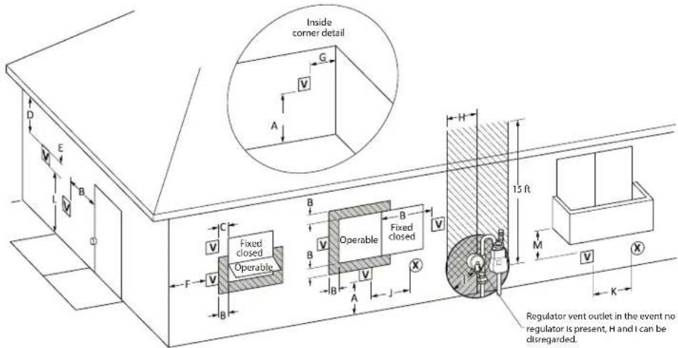
VENT TERMINAL
☒ AIR SUPPLY INLET
AREA WHERE TERMINAL IS NOT PERMITTED
Canadian Installations ^1
US Installations ^2
| A= Clearance above grade, vcanda, porch, deck or balcony. | 12 inches (30 cm) 12 inches (30 cm) | |
| B= Clearance to window or door that may be opened. | 6 in (15 cm) for appliances ≤ 10,000 Btuh (3 kW),12 in (30 cm) for appliances > 10,000 Btuh (3 kW) and ≤ 100,000 Btuh (30 kW),36 in (91 cm) for appliances > 100,000 Btuh (30 kW) | 6 in (15 cm) for appliances ≤ 10,000 Btuh (3 kW),12 in (30 cm) for appliances > 10,000 Btuh (3 kW) and ≤ 50,000 Btuh (15 kW),12 in (30 cm) for appliances > 50,000 Btuh (15 kW) |
| C= Clearance to permanently closed window. 0 in (0 cm) 0 in (0 cm) | ||
| D= Vertical Clearance to ventilated soffit located above the terminal within a horizontal distance of 2 feet (61 cm) from the center line of the terminal. | 12 in (30 cm) 12 in (30 cm) | |
| E= Clearance to unventilated soffit. 12 in (30 cm) | 12 in (30 cm) | |
| F= Clearance to outside corner. 24 in (61 cm) 24 in (61 cm) | ||
| G= Clearance to inside corner. 18 in (46 cm) 18 in (46 cm) | ||
| H = Clearance to each side of center line extended meter/regulator assembly. above | 3 feet (91 cm) within a height 15 feet (4.6 m) | 3 ft (91 cm) within a height of 15 ft (4.6 m) |
| I = Clearance to service regulator vent outlet. 3 feet (91 cm) 3 feet (91 cm) | ||
| J = Clearance to nonmechanical air supply inlet to building or the combustion air inlet to any other appliance.. | 6 in (15 cm) for appliances ≤ 10,000 Btuh (3 kW),12 in (30 cm) for appliances > 10,000 Btuh (3 kW) and ≤ 100,000 Btuh (30 kW),36 in (91 cm) for appliances > 100,000 Btuh (30 kW) | 6 in ( 15 cm) for appliances ≤ 10,000 Btuh (3 kW),12 in (30 cm) for appliances > 10,000 Btuh (3 kW) and ≤ 50,000 Btuh (15 kW),12 in (30 cm) for appliances > 50,000 Btuh (15 kW) |
| K = Clearance to mechanical air supply inlet. | 6 feet (1.83 m) | 3 feet (91 cm) above if within 10 feet (3 m) horizontally. |
| L = Clearance above paved side walk or paved driveway located on public property. | 7 feet (2.13 m) | 7 feet (2.13 m) for mechanical draft systems (Category I appliances); vents for Category II and IV appliances cannot be located above public walkways or other areas where condensate or vapor can cause a nuisance or hazard. |
| M = Clearance under veranda, porch, deck or balcony. | 12 in (30 cm) ‡ | 12 in (30 cm) ‡ |
^1 In accordance with the current CSA B149.1 Natural Gas and Propanc Installation Code
^2 In accordance with the current ANSI Z223.1/NFPA 54 National Fuel Gas Code
Permitted only if veranda, porch, deck, or balcony is fully open on a minimum of two sides beneath the floor.
INSTALLATION INSTRUCTIONS

Venting for Direct-Vent Water Heater (cont.)
Horizontal Vent Considerations
WARNING:
Moisture in the flue gas will condense as it leaves the vent terminal. In cold weather this condensate can freeze on the exterior wall, under the eaves, and on surrounding objects. Some discoloration to the exterior of the building is to be expected. However, improper location or installation can result in severe damage to the structure or exterior finish of the building.
- DO NOT locate vent terminal on the side of a building with prevailing winter winds. This will help prevent water lines from freezing and moisture from freezing on walls and under eaves.
- DO NOT locate vent terminal too close to shrubbery, since flue gases may damage them.
- All painted surfaces should be primed to lessen the chance of physical damage. Painted surfaces will require maintenance.
- Guard against accidental contact with people and pets.
Indoor Tankless Water Heaters
WARNING:
For multiple-unit installation, a minimum distance between vent terminations must be maintained to prevent recirculation of vent gases. Maintain a horizontal center-to-center distance between vent terminations of 19 in. (48 cm) for two-unit installation, or 21 in. (53 cm) for installation of three or more units*.
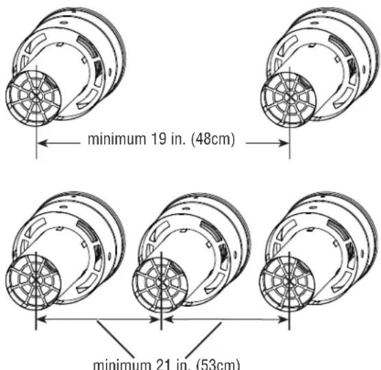
* Vents cannot be stacked vertically.

- DO NOT terminate vent directly on brick or masonry surfaces. A rust-resistant, sheet-metal backing plate is recommended behind the vent.
- Caulk all cracks, seams, and joints within 6 ft. (1.8 m) of the vent terminal.
- Caulk around wall faceplate for weather-tight seal.
- DO NOT extend exposed vent pipe of indoor water heaters outside of the building.
- This water heater requires its own separate venting system. DO NOT connect the exhaust vent to an existing vent pipe or chimney.

- Install indoor and outdoor water heaters such that air inlet and flue outlet are above anticipated snow level.
INSTALLATION INSTRUCTIONS

Venting for Direct-Vent Water Heater
Horizontal Vent Installation
WARNING:
Follow the vent manufacturer's installation instructions since design might vary from manufacturer to manufacturer. Improper vent installation can result in death, personal injury, product damage, and/or poor performance.
CAUTION:
Use UL-approved Category III Stainless Steel vent material only. No other vent material is permitted for use with this appliance.
Outer casing can be galvanized aluminum or other material.
Fasteners will vary depending on the wall type.
natural_image
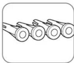
Line drawing of four identical cylindrical objects arranged horizontally (no text or symbols)For particle board or composite sheathing, use 4 hollow wall anchors. The anchors should be at least 1/8 in. (0.3 cm) in diameter and the appropriate length for the sheathing thickness.

natural_image
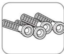
Illustration of four screws with cross-shaped fasteners (no text or symbols)For plywood or solid wood sheathing or members, use 4 #10 x 1 1/4-in. wood screws.
natural_image
Illustration of multiple bolts or fasteners arranged in a row (no text or symbols)For masonry walls, use suitable masonry anchors long enough to pass through the wall.
Reinstall the decorative sheathing around the faceplate. The decorative sheathing may be painted to match the exterior decor.

natural_image
Diagram of a pipe being inserted into a socket, showing internal structure and mounting points (no text or symbols)Apply high temperature silicone sealant or silicone/latex caulk around the vent section. Completely seal where it passes through the wall plate and where it is attached to the structure. This will provide a weather seal for the system, so it must be a good seal.

natural_image
Diagram of a cylindrical pipe with internal layered structure and two dashed connection points (no text or symbols)Attach the female end of the next vent pipe section to the male end of the 3-in./5-in. (7.6-cm/12.7-cm) concentric vent pipe. Push firmly on the pipe until the outer jacket has made contact with the snap ring on the male end of the concentric vent pipe section. Secure the two pipe sections with the provided self-tapping screws.
NOTICE:
When fully assembled, the outer female end will overlap the male end about 1 in. (2.5 cm).
DO NOT attempt to fabricate or adapt other vent pipe or materials to this venting.
INSTALLATION INSTRUCTIONS

Venting for Direct-Vent Water Heater
Horizontal Vent Installation (cont.)
Using a thick bead of high temperature silicone, seal the overlapping area of the outer 5-in. (12.7-cm) pipe.

natural_image
Line drawing of a pipe elbow joint with a base mount (no text or symbols)Attach required vent sections between the water heater collar and the horizontal vent termination.
Typical Horizontal Termination with 1/4 In. Per Foot of DOWNWARD Slope

CAUTION:
The condensate collector must be used in horizontal terminations if vertical rise in the vent system exceeds 2 feet (610 mm).*
NOTICES:
- Maintain the proper clearance between the vent pipe and combustible or noncombustible materials as described on page 16.
- A clearance of 0 in. (0 cm) is allowed between the air intake pipes and combustible material.
- Use proper support for the vent and air intake pipes as described on "Venting".
- Support method used should isolate the vent pipe from floor joists or other structural members. This helps prevent transmission of noise and vibration.
- DO NOT support, pin, or secure the venting system in a way that restricts the normal thermal expansion and contraction of the chosen venting material.
INSTALLATION INSTRUCTIONS

Venting for Direct-Vent Water Heater
Vertical Vent Installation
⚠ WARNING:
Follow the vent manufacturer's installation instructions since design might vary from manufacturer to manufacturer. Improper vent installation can result in death, personal injury, product damage, and/or poor performance.
NOTICE:
Only Rheem-approved termination and parts should be used during installation.
Install a fire stop plate at every penetration of a floor or ceiling, whenever the vent is not running through a fire-rated shaft.
Maintain the recommended air space clearance to combustible materials and building insulation.
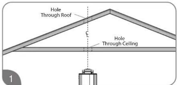
Cut a hole through the roof and interior ceiling to accommodate the vent pipe.
natural_image
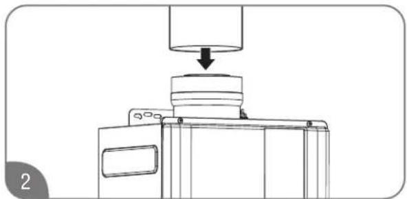
Technical line drawing of a mechanical assembly with a downward arrow indicating process (no text or symbols)Complete the vent pipe installation to the water heater vent collar. If required, use high temperature silicone sealant where the vent connector joins the water heater.
natural_image
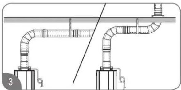
Technical line drawing of two pipe fittings with a central pipe and support structures (no text or symbols)Support vertical and horizontal runs as described on "Venting". Vertical supports are required every 4 ft. (1.2 m) along a vertical pipe route, after every transition to vertical, and after every offset elbow.
NOTICE:
Free-standing vent pipe that penetrates a roof/ceiling requires another means of support from a second location.
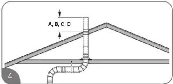
Determine the vent terminal height and install the vent pipe accordingly. Refer to "Vertical Vent Terminal Location" on this Use and Care Manual for clearance requirements.

natural_image
Diagram of a roof structure with a pipe and a triangular load, no text or symbols presentInstall adequate flashing where the vent pipe passes through the roof.
INSTALLATION INSTRUCTIONS

Venting for Direct-Vent Water Heater
Vertical Vent Terminal Location

The following chart with diagrams details the minimum dimensional information needed to determine the proper location of the vertical vent terminal for direct-vent indoor tankless water heaters:
| Location | U.S. Installation Requirements1 | Canadian Installation Requirements2 |
| A = Minimum clearance above the roof level. 12 in. (30.5 cm) | above roof level. 18 in. (45.7 cm) above roof level. | |
| B = Minimum clearance above anticipated snow level. 12 in. (30.5 cm) above anticipated snow level. | 12 in. (30.5 cm) above anticipated snow level. | |
| C = Maximum clearance above roof level (without additional vent support). | 24 in. (61 cm) above roof level. 24 in. (61 cm) | above roof level. |
| D = Maximum clearance above anticipated snow level (requires additional vent support). | 24 in. (61 cm) above anticipated snow level. | 24 in. (61 cm) above anticipated snow level. |
| E = Required vent clearance from any gable, dormer, or other roof structure with building access (i.e., vent, window). | 4 ft. (1.2 m). 4 ft. (1.2 m). | |
| F = Required vent clearance from any forced air inlet, including dryer and furnace air inlets. | 10 ft. (3 m) 6 ft. (1.8 m) |
1 In accordance with current ANSI Z223.1/NFPA 54 National Fuel Gas Code.
2 In accordance with current CAN/CSA B149.1 Installation Codes.
NOTICE:
Only manufacturer-approved termination and parts should be used during installation.
INSTALLATION INSTRUCTIONS

Venting for Direct-Vent Water Heater
Standard Vertical Vent Termination

INSTALLATION INSTRUCTIONS

Water Quality
Water quality must be taken into account when installing and maintaining the water heater. Water conditions outside of the levels specified below affect and may damage the water heater. Please note that the limited warranty provided with the water heater does not cover defects, malfunctions or failures resulting from water conditions that are not in accordance with the specifications in the table below.
If you nonetheless install this water heater where the water conditions are not within the levels specified in
the table below, Rheem recommends that you take the following steps:
- Install a water treatment device or water softener at the same time as the original installation of the water heater. Rheem offers a water treatment accessory that can be installed with the water heater. (See below).
- Flush the water heater's heat exchanger regularly. Rheem offers a flush kit and isolation valves to help remove scale build up. (See below)
| Chart for Recommended Water Quality Levels | |||||||||
| pH | (Total Dissolved Solids) TDS | Free Carbon Dioxide ( CO_2 ) | Total Hardness | Aluminum | Chlorides Copper | Iron Manganese | Zinc | ||
| 6.5–8.5 | Up to 500 mg/L Up to 15 mg/L | Up to 200 mg/L | 0.05 to 0.2 mg/L | Up to 250 mg/L | Up to 1.0 mg/L | Up to 0.3 mg/L | Up to 0.05 mg/L | Up to 5 mg/L | |
Cited reference: National Secondary Drinking Water Regulations
Accessory part numbers listed below. See Parts and Accessories Catalog for more information.
| Accessory Kit | Replacement Filter | Tankless Flush Kit | Tankless Isolation Valve | |
| AllClear Water Treatment Kit | RTG20251 | RTG20252 | RTG20124 RTG20220AB | |
| Scale Prevention Device | RTG20246 | RTG20247 | ||
Water Supply
CAUTION:
This water heater MUST ONLY be used with the following water supply conditions to prevent product damage and operation failure.
Clean, potable water free of corrosive chemicals, sand, dirt, or other contaminates.
Inlet water temperatures above 32^ F ( 0^ C), but not exceeding 120^ F ( 49^ C).
DO NOT reverse the HOT and COLD water connections.
DO NOT connect this heater to water lines previously used for space heating. All water piping and components shall be suitable for potable water.
With recommended water quality (See chart above).
Thermal Expansion
A thermal expansion tank will be required if the water heater is installed in a system with a recirculation or storage tank. This prevents damage to the heater, related piping, and the relief valve.
NOTICE:
Replacing the relief valve will not correct the problem!
The expansion tank is designed with a built-in air cushion that compresses as the system pressure increases. This relieves the over-pressure condition and eliminates the repeat operation of the relief valve.
For other approved methods of thermal expansion, contact an installing contractor, water supplier, or plumbing inspector.
Water Supply Connections
CAUTION:
IMPORTANT—DO NOT apply heat to the HOT or COLD water connections. If sweat connections are used, sweat tubing to the adapter before fitting the adapter to the water connections on the water heater. Any heat applied to the water supply fittings will permanently damage the internal components of the water heater.
NOTICE:
In cold environments, ice can accumulate in the water heater's connectors. Plug in the water heater
power cord for approximately 10 minutes before making these connections. This will melt any ice buildup.
Plumbing should be carried out by a qualified plumbing contractor in accordance with local codes.
Only use approved plumbing materials.
To allow the full flow capacity, it is recommended to keep water inlet and outlet pipes 3/4-in. (1.9-cm) diameter or larger.
To conserve energy and to prevent freezing, insulate both COLD and HOT water supply lines. DO NOT insulate the pressure-relief valve.
INSTALLATION INSTRUCTIONS

Water Supply
Recirculation
Direct recirculation is allowed, provided the loop is thermostatically controlled, and a timer is used to turn the pump off during off peak periods. The pump must be sized for a minimum of 5 gpm at 25 ft of head plus building head. A 10°F difference between the loop thermostat setting and water heater temperature setting must be maintained.
To ensure proper operation of the water heater, follow these water pressure guidelines.
Operation of the water heater requires a minimum water pressure of 14 psi (97 kPa) and a minimum activation water flow rate of 0.4 gpm (1.5 lpm).
Continuous operation of the water heater requires a minimum water flow rate of 0.25 gpm (1.01 lpm).
Water pressure of 40 psi (276 kPa) is required to achieve maximum flow rate.
To maintain proper performance, there must be sufficient water supply pressure.
Required Water Pressure = Min. Operating Water Pressure (14 psi [97 kPa])
+ Pipe Pressure Loss
+ Faucet Pressure Loss
+ Safety Margin (more than 5 psi [34 kPa]).
To supply HOT water to upper floors, additional water pressure will be required (0.44 psi [3 kPa] per foot of height). Calculate the distance between the water inlet of the water heater (ground level) to the HOT water faucet farthest away from the water heater (upper floor level).
- Well water systems should be set to ensure a minimum system pressure of 40 psi (276 kPa). The pressure should remain constant and stable during the operation of the water heater.
- Gravity water pressure is not recommended. When the water is supplied from a water supply tank, the height of the tank, the diameter of the supply pipes, and their relation to water pressure need to be taken into consideration.
Water Supply Installation
NOTICE:
- Use only Teflon tape on all COLD and HOT water connections.
- If the water flow resistance of a showerhead is too high, the burner in the water heater will fail to ignite. Keep all showerheads clean from debris that could cause additional pressure drop.
- If using mixing valves on the outlet, choose one that prevents COLD water pressure from overcoming HOT water pressure.
- If multiple water heaters are installed in a manifold system, the water piping MUST be in "parallel" and the water pressure at each water heater should be 40 psi (276 kPa).

Install a COLD water shut-off valve near the inlet line on the water heater. This valve will be used for servicing and draining purposes.
NOTICE:
It is not recommended to use pipes with smaller diameters than the water supply connection of the water heater.

natural_image
Illustration of a hand pouring water from a bucket into a pipe with a valve (no text or symbols)Before attaching the water line to the water heater, open the shut-off valve. Run the water until it has purged all contaminants (sand, debris, air, caulking).

natural_image
Technical diagram showing mechanical assembly with pipes and components, no visible text or symbolsInstall a service valve on the end of the COLD water supply line and connect it to the water inlet on the water heater.
INSTALLATION INSTRUCTIONS

Water Supply
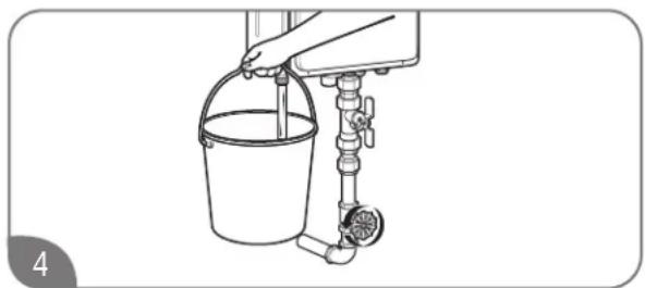
natural_image
Line drawing of a hand pouring liquid into a bucket using a water dispenser (no text or symbols)Open the drain valve in the COLD water outlet line to check the water flow through the water heater.

natural_image
Technical line drawing of a mechanical assembly with no visible text or symbolsClose the shut-off valve and remove, clean, and replace the water filter.
NOTICE:
Be sure to connect the COLD water inlet and the HOT water outlet as shown on the water heater. If reversed, the water heater will not function.
The flow rate of HOT water may vary when more than two faucets (appliances, fixtures, etc.) are being used simultaneously.
The pipes MUST be completely drainable. If the HOT water faucets are located at a point higher than the water heater, place a drain valve at the lowest point.

natural_image
Technical line drawing of a piping system with valves and fittings (no text or symbols)It is recommended to use unions and flexible copper connections at the COLD and HOT water lines. They allow the water heater to be disconnected easily for servicing.
Use the following guidelines when connecting the HOT WATER OUTLET:
Connections between the water heater and point(s) of use should be as short as possible.
Local codes shall govern the piping used for water connections.
To conserve energy and to prevent freezing, insulate both COLD and HOT water supply lines. DO NOT insulate drain line or pressure-relief valve.
Alternate Water Piping Arrangement With Preferred Valve Kit
Service valve kits can attach to all tankless water heater systems. All kits include two full-port isolation valves to be used in the COLD and HOT water lines. When installed, these valves allow one person full diagnostic testing and ease of flushing the system. Contact your distributor or place of purchase for availability and installation information.
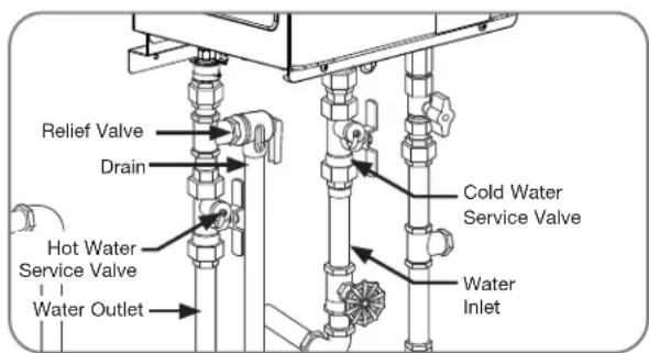
INSTALLATION INSTRUCTIONS

Water Supply
Relief Valve
A new pressure-relief valve, complying with the Standard for Relief Valves and Automatic Gas Shut-Off Devices for Hot Water Supply Systems, ANSI Z21.22/CSA 4.4, must be installed at the HOT water outlet connection of the water heater during installation. Local codes shall govern the installation of any relief valves.
NOTICE:
- The following drawing illustrates a pressure-only relief valve. If local codes require a combination temperature and pressure-relief valve, you may need to install an extension piece to ensure that the relief valve probe is not directly in the flow path of the water.
- Local codes govern the installation of relief valves. If local codes require that a temperature and pressure-relief valve be installed, the manufacturer recommends a type 40XL Watts temperature and pressure-relief valve or equivalent model be used.
- Manual operation of relief valves should be performed at least once a year.
- If the relief valve on the system discharges periodically, a problem exists. Turn off the water heater, unplug the unit, and call for service.

One end of the relief valve discharge line connects to the HOT water outlet pipe as shown above. The other end of the pipe should be routed to a suitable drain to eliminate potential water damage.
For safe operation of the water heater, be sure that:
The pressure rating of the relief valve must not exceed 150 psi (1,034 kPa) or the maximum working pressure of the water heater. (See the rating plate on the water heater.)
The BTUH rating of the relief valve must equal or exceed the BTUH input of the water heater. (See the rating plate on the water heater.)
No valve of any type should be installed between the relief valve and the water heater.
Discharge from the relief valve should be piped to a suitable drain. Piping used should be of a type approved for the distribution of hot water.
HOT and COLD water lines should be insulated up to the water heater. See "Water Supply Installation".
The discharge line must be NO SMALLER than the outlet of the relief valve. The drain line must pitch downward to allow for complete drainage of the line and the valve.
The end of the discharge line should not be threaded or concealed and should be protected from freezing. No valve of any type, restriction, or reducer coupling should be installed in the discharge line.
INSTALLATION INSTRUCTIONS

Water Supply
Hot and Cold Pipe Insulation Installation
⚠️WARNINGS:
When pipe insulation is not rated for the appropriate weather conditions, install electric heat tracing or equivalent to prevent freezing of the pipes.
DO NOT insulate or block drain valve on the hot outlet fitting.
If pipes are allowed to freeze, the water heater and the pipes may malfunction or leak due to freezing water.
NOTICE:
The hot and cold water supply pipes should be insulated to provide additional freeze protection.
For increased energy efficiency, use pipe insulation as shown in the diagram. Insulate the pipes all the way to the top. DO NOT cover any drain or pressure-relief valve(s).
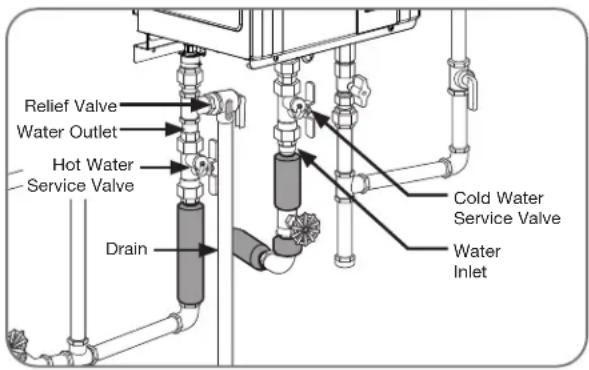

Gas Supply
Gas Supply System
WARNING:
DO NOT attempt to convert this water heater for use with a different type of gas other than the type shown on the rating plate. Doing so could result in death, personal injury, explosion or fire, product damage, and/or poor operating conditions or performance.
NOTICE:
Gas piping shall be in accordance with local utility company requirements and/or in the absence of local codes, use the latest edition of National Fuel Gas Code (NFGC), ANSI Z223.1. In Canada, use the latest edition of CAN/CSA B149.1, Natural Gas and Propane installation code.
Apply a thin coat of pipe compound to all threaded male ends. Compound must be of the type resistant to the action of LP gas.
To ensure proper water heater operation, the gas pipe and gas meter must be sized correctly.
If flexible connectors are used, the minimum
inside diameter must be 3/4" or greater and the rated capacity of the connector must be equal to or greater than the BTU capacity of the water heater. See manufacturer information for the gas connector. Lengths over 36 inches are not recommended.
DO NOT use excessive force when tightening the pipe sections. Excessive force can damage the water heater, especially when Teflon pipe compound is used.

INSTALLATION INSTRUCTIONS

Gas Supply
Gas Piping
Pipe-Sizing Procedure
The gas supply system must be properly sized to ensure the proper operation of this tankless water heater as well as all the gas appliances on the system. Failure to ensure the gas system, (meter, regulators, and piping) are properly sized could result in improper operation of this or other gas appliances. Insufficient gas pressure/supply can cause ignition issues, lockouts, or operating conditions that could lead to an appliance failure, improper combustion, carbon monoxide, sooting, or fire. Gas line sizing is based on gas type, the pressure drop in the system, the gas pressure supplied, and the gas line type. For gas pipe sizing in the United States, refer to the National Fuel Gas Code, (NFPA 54, ANSI Z223.1). For Canadian gas pipe sizing, refer to the Natural Gas and Propane Installation Code CAN/CSA B149.1.
These simplified instructions only address low pressure gas systems using Schedule 40 Metallic Pipe (Black Iron). For hybrid gas systems, high pressure main lines with regulators at the appliances, gas systems piped with corrugated stainless steel tubing (CSST), or Propane gas systems.
Determining the required regulator and gas meter size.
Find the BTU capacity of each appliance on the system. This information is located on a rating label attached to the appliance. Total the BTU of all the appliances together and divide that by the heating value of the fuel (for natural gas the average is 1,024 or 2,546 for propane). This will give you the total cubic feet per hour of gas required for the system.
At your gas meter/regulator there will be a rating plate that gives the cubic feet per hour capacity of that equipment. If the total gas required for the system is greater than the rating of the meter/regulator then the local gas company will need to be contacted in order to upgrade the meter/regulator for the system.
Gas Input of
Cubic Feet
Per Hour (CFH) =
Water Heater (Btu/h)
Heating Value of Gas (BTU/FT³)
Determining the required pipe size.
The gas system is designed to operate at a certain maximum pressure drop. A pressure drop greater than what is permissible can cause operational issues with the gas appliances. The National Fuel Gas Code (NFPA 54, ANSI Z223.1 2012) allows for three pressure drop levels, a 0.3 inch W.C., (see table 2); a 0.5 inch W.C., (see table 3) and a 3.0 inch W.C., (see table 4) pressure drop for natural gas. Only a 0.5 inch W.C. pressure drop is allowable with Propane (see table 5). For Canadian installations the maximum allowable pressure drop is 0.5 inch W.C., (see table 3).
Measure the inlet gas pressure to the system using a manometer. For Natural Gas, if the inlet pressure is less than 8.0 inches W.C. then use Table 2 or 3 for your gas pipe sizing. Table 4 can only be used if the inlet gas pressure is 8.0 inches W.C. or greater. Table 4 cannot be used for Canadian installations.
The gas piping system consists of a main trunk line that runs from the meter/regulator and branch lines that run from the trunk line to the individual appliances. A branch may carry gas for more than one appliance.
The trunk line must be sized to carry the entire load of all the gas appliances on the system. As with determining the meter/regulator size, total the BTU of all the appliances together and divide that by the heating value of the fuel (for natural gas the average is 1,024 or 2,546 for propane). This will give you the total cubic feet per hour of gas required for the trunk line. Measure the total length of the line Refer to Table(s) 2, 3, or 4 and find the number closest to but higher than the total cubic feet per hour requirement calculation. This will tell you the minimum size that the trunk line must be.
Each branch line must be sized to carry the load of the appliance(s) attached to it. If more than one appliance is on a branch total the BTU and as with the trunk line divide that by the heating value of the fuel. Refer to Table(s) 2, 3, or 4 and find the number closest to but higher than the total cubic feet per hour requirement calculation for the branch and appliance(s). This will tell you the minimum size for that branch line and appliance.
INSTALLATION INSTRUCTIONS

Gas Supply
Final Considerations
If this water heater is replacing an existing water heater, it is important to verify the capacity of the gas system. Check the capacity of the meter/regulator, and verify the pipe lengths and sizes.
An improperly sized gas system will cause operational issues with this water heater. Other appliances on the gas system may be affected as well.
Flexible Gas Connectors may be used; however, the BTU capacity of the connector must be checked. Each connector has a capacity label on it, verify that the connector has a BTU capacity greater than that of the water heater. An undersized flexible gas connector will cause operational issues with this water heater.
Half-inch gas lines are permissible provided the gas system meets certain requirements. First, the gas
pressure on the system must be 8.0 inch W.C. or greater. Second the capacity of the pipe as outlined in Table 4 is followed. If the existing pipes are too small it could cause a pressure drop greater than 3.0 inch W.C. and will cause operational issues with this water heater as well as other gas appliances on the system. This is an example, in US, refer to current National Fuel Gas Code, NFPA 54 for correct pipe sizing chart, and in Canada, refer to current Natural Gas and Propane Installation Code CAN/CSA B149.1.
| Table 2 - Pipe-Sizing - Natural Gas | |||||
| Schedule 40 Metallic Pipe (Black Iron)Inlet System Pressure: Less than 2 PSI (55 inches W.C.)Allowable Pressure Drop: 0.3 inches W.C.Specific Gravity : 0.60(Capacity in cubic feet per hour) | |||||
| Length Pipe Size (Inches) | |||||
| 12 34 1 14 112 | |||||
| 10 131 273 | 514 1,060 1,580 | ||||
| 20 90 188 | 355 726 1,090 | ||||
| 30 72 151 | 284 583 873 | ||||
| 40 62 129 | 243 499 747 | ||||
| 50 55 114 | 215 442 662 | ||||
| 60 50 104 | 195 400 600 | ||||
| 70 46 95 179 | 368 552 | ||||
| 80 42 89 167 | 343 514 | ||||
| 90 40 83 157 | 322 482 | ||||
| 100 38 79 | 304 455 | ||||
| Information in this chart obtained from NFPA 54, ANSI Z223.1 - 2012 Table 6.2(a) | |||||
| Table 4 - Pipe-Sizing - Natural Gas | ||||||
| Schedule 40 Metallic Pipe (Black Iron)Inlet System Pressure: 8.0 inches W.C. or greater, but Less than 2 PSI (55 inches W.C.)Allowable Pressure Drop: 3.0 inches W.C.Specific Gravity : 0.60(Capacity in cubic feet per hour) | ||||||
| Length Pipe Size (Inches) | ||||||
| 12 34 1 14 112 | ||||||
| 10 454 919 | 1,787 | 3,659 | 5,497 | |||
| 20 312 652 | 1,228 | 2,522 | 3,778 | |||
| 30 250 524 | 986 | 2,025 | 3,778 | |||
| 40 214 448 | 844 | 1,733 | 2,597 | |||
| 50 190 387 | 748 | 1,536 | 2,302 | |||
| 60 172 350 | 678 | 1,392 | 2,085 | |||
| 70 158 331 | 624 | 1,280 | 1,919 | |||
| 80 147 308 | 580 | 1,191 | 1,785 | |||
| 90 138 289 | 544 | 1,118 | 1,675 | |||
| 100 131 | 273 | 514 | 1,036 | 1,582 | ||
| Information in this chart obtained from NFPA 54, ANSI Z223.1 - 2012 Table 6.2(c) | ||||||
| Table 3 - Pipe-Sizing - Natural Gas | |||||
| Schedule 40 Metallic Pipe (Black Iron)Inlet System Pressure: Less than 2 PSI (55 inches W.C.)Allowable Pressure Drop: 0.5 inches W.C.Specific Gravity : 0.60(Capacity in cubic feet per hour) | |||||
| Length Pipe Size (Inches) | |||||
| 1234 1 14 1 14 | |||||
| 10 172 360 | 678 1390 2090 | ||||
| 20 118 247 | 466 957 1430 | ||||
| 30 95 199 | 374 768 1150 | ||||
| 40 81 170 | 320 657 985 | ||||
| 50 72 151 | 284 583 873 | ||||
| 60 65 137 | 257 528 791 | ||||
| 70 60 126 | 237 486 728 | ||||
| 80 56 117 | 220 452 677 | ||||
| 90 52 110 | 207 424 635 | ||||
| 100 50 104 | 195 400 600 | ||||
| Information in this chart obtained from NFPA 54, ANSI Z223.1 - 2012 Table 6.2(b) | |||||
| Table 5 - Pipe-Sizing - Undiluted Propane | |||||
| Schedule 40 Metallic Pipe (Black Iron)Inlet System Pressure: 11 inches W.C.Allowable Pressure Drop: 0.5 inches W.C.Specific Gravity : 1.5(Capacity in cubic feet per hour) | |||||
| Length Pipe Size (Inches) | |||||
| 10 291 608 | 1150 2350 35 | 20 | |||
| 20 200 418 | 787 1620 2420 | ||||
| 30 160 336 | 632 1300 1940 | ||||
| 40 137 287 | 541 1110 1660 | ||||
| 50 122 255 | 480 985 1480 | ||||
| 60 110 231 | 434 892 1340 | ||||
| 80 101 212 | 400 821 1230 | ||||
| 100 94 197 | 372 763 1140 | ||||
| 125 89 185 | 349 716 1070 | ||||
| 150 84 175 | 330 677 1010 | ||||
| Information in this chart obtained from NFPA 54, ANSI Z223.1 - 2012 Table 6.3(d) | |||||
INSTALLATION INSTRUCTIONS

Gas Supply
Gas Supply Installation

natural_image
Technical line drawing of a piping system with valves and valves (no text or symbols)Install the manual gas appliance shut-off valve to the gas connection at the water heater. The shut-off is supplied with the water heater.

natural_image
Pure technical diagram of pipe connections without any text, numbers, or symbolsInstall a ground joint union or ANSI design-certified semi-rigid or flexible gas appliance connector to the open end of the manual gas appliance shut-off valve. The (NFGC) ANSI Z223.1 and CAN/CSA B149.1 codes mandate the use of manual gas shut-off valves.

natural_image
Pure diagram of piping connections without any text, numbers, or symbolsInstall a manual gas supply line shut-off valve to the end of the gas supply line.
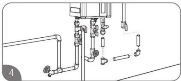
natural_image
Technical line drawing of a piping system with valves and fittings (no text or labels)Using the proper-size piping, fittings, and components, build the gas supply line to the water heater.
NOTICE:
The gas supply line should be a minimum of 3/4-in. (1.9-cm) black steel pipe or other approved gas piping material.

natural_image
Pure technical diagram of piping connections without any text, numbers, or symbolsInstall a sediment trap at the lowest portion of the gas line.
The inlet gas pressure to the water heater must NOT exceed 10.5 in. w.c. (2.6 kPa) for natural gas and 13 in. w.c. (3.2 kPa) for LP gas. For purposes of input adjustment, the minimum inlet gas pressure (with main burner on) is shown on the water heater rating plate. If high or low gas pressures are present, contact your gas supplier for correction.
INSTALLATION INSTRUCTIONS

Gas Supply
Leak Testing
WARNING:
Never use an open flame to test for gas leaks, because death, personal injury, and/or property damage can result.
The water heater and its gas connections MUST be leak-tested at normal operating pressures before the unit is placed in operation. These tests should also include all factory connections.

natural_image
Technical illustration of mechanical assembly with hexagonal components and a clamping tool (no text or symbols)Turn on the gas shut-off valve(s) to the water heater.
Use a soapy water solution to test for leaks at all the connections and fittings. If bubbles are seen, it indicates a gas leak that must be corrected.
Contact a qualified service technician.
Pressure Testing the Gas Supply System
CAUTION:
If inlet gas pressure is out of allowable range [4.0" w.c. (1.0kPa) - 10.5" w.c. (2.6kPa)] for Natural Gas, or [8.0" w.c. (2.0kPa) - 13.0" w.c. (3.2kPa)] for LP gas, a gas pressure regulator must be installed to maintain the allowable inlet gas pressure.

natural_image
Technical line drawing of a mechanical piping assembly with valve and valve fittings (no text or symbols)The water heater and its manual gas shut-off valve must be disconnected from the gas supply piping system whenever the pressure testing will exceed 1/2 psi (14 in. w.c. [3.5 kPa]).
The water heater must be isolated from the gas piping system whenever the pressure testing will be less than and/or up to 1/2 psi (14 in. w.c. [3.5 kPa]). Closing the manual gas shut-off valve will isolate the water heater from the gas piping system.
INSTALLATION INSTRUCTIONS

Gas Supply
High-Altitude Installation
WARNING:
DO NOT install this water heater at elevations above 2000 ft. (610 m) without the proper adjustments. Failure to install a water heater suitable for the altitude at the location it is intended to serve can result in improper operation of the appliance resulting in property damage and/or producing carbon monoxide gas, which could result in personal injury or death.

Electrical Wiring
DANGER:
Shock Hazard – Before servicing the water heater, turn off the electrical power to the water heater at the main disconnect or circuit breaker. Failure to do so will result in death or serious personal injury.
WARNING:
Field wiring connections and electrical grounding must comply with local codes or, in the absence of local codes, with the latest edition of the National Electrical Code, ANSI/NFPA 70, in the U.S., or Canadian Electrical Code, CAN/CSA C22.1, Part 1, in Canada.
CAUTION:
Labeling all wires prior to disconnection is recommended. Wiring errors can cause personal injury, product damage, and/or dangerous operating conditions. Verify correct operation after servicing.
NOTICE:
- DO NOT connect power until venting installation is complete (see Venting Installation).
- Wait ninety (90) seconds after power is connected for the first time to initiate operation of the water heater.
- Power consumption is up to 100 Watts during normal operation, 3-5 Watts during standby, (waiting to run), and up to 200 Watts during the freeze protection operation.
Power Cord
The electric power supply requirement for this water heater is 120 VAC/60 Hz, 2 Amps.
A dedicated circuit is recommended for the water heater. DO NOT connect to a GFCI or AFCI circuit. Multiple units may be connected to a single circuit up to the circuit rating.
NOTICE:
For installations above 2000 ft. (610 m) elevation, contact a qualified service technician to make the proper altitude adjustments. You can also contact your local gas supplier, place of purchase, or call the Rheem Customer Service phone number listed in the "Call for Assistance" section. See "High-Altitude DIP Switch Adjustments" for additional information.
DO NOT use 3-prong to 2-prong adapters. DO NOT use power strips or multiple outlet adapters.
All direct-vent gas models come with a three-prong power cord. Only use this power cord and a matching grounded electrical outlet.
All outdoor gas models do not come with a power cord. Only hard-wire to an appropriate power outlet with a ground terminal.
Keep any excess length of the power supply cord on the outside of the water heater.
If local codes require hard-wiring, see instructions for "Hard-Wiring the Electrical Connections" below.
Hard-Wiring the Electrical Connections
Wiring should be performed by a qualified electrician in accordance with local codes.
The water heater requires a properly grounded 120 VAC/60 Hz power supply. Multiple water heaters may be connected to a single circuit up to that circuit's rating.
DO NOT connect grounding wire to water pipes, gas pipes, telephone cables, lighting conductor circuits, or to any other grounding circuits that require a GFCI or AFCI (arc fault circuit interrupter).
An ON/OFF switch must be provided and installed for the incoming 120 VAC power supply.
Wire the water heater exactly as shown in the wiring diagram. This wiring diagram can also be found inside the water heater cover panel.
The green screw is provided in the enclosure for a grounding connection.
Connect the live wire to the black wire and neutral wire to the white neutral wire.
INSTALLATION INSTRUCTIONS
Wiring Diagram

flowchart
graph TD
    A["ON MARCHE"] --> B["SW2 MAX BUTTON"]
    B --> C["SW3 ADJUSTER BUTTON"]
    C --> D["SW1 MIN BUTTON"]
    D --> E["SW3 SW1 SW2 SW3"]
    E --> F["DIP1 DIP2"]
    F --> G["SW3 SW3"]
    G --> H["CIRCUIT BOARD PLAQUE DE CIRCUIT"]
    H --> I["LED"]
    I --> J["FOR INDIOOR DIRECT-VENT MODEL ONLY UNIQUERMENT POUR MODELE DE CONDENSAGE"]
    J --> K["FOR CONDENSING MODEL ONLY UNIQUERMENT POUR MODELE DE CONDENSAGE"]
    K --> L["FOR OUTDOOR MODEL ONLY UNIQUERMENT POUR MODELE À USAGE EXTÉRIEUR"]
    L --> M["FAN MOTOR VENTILATEUR DU MOTEUR FM"]
    M --> N["ANTI-FROST HEATER CHAUFFAGE ANTI-GIVRE W W W W W W W W W W W W W W W W W W W W W W W W W W W W W W W W W W W W W W W W W W W W W W W W W W W W W W W W W W W W W W W W W W W W W W W W W W W W W W W W W W W W W W W W W W W W W W W W W W W W"]
    N --> O["FOR INDOOR DIRECT-VENT MODEL ONLY POUR MODELE INTÉRIEUR À VENT DIRECT SEULEMENT G Y GND"]
    O --> P["AC 120V GND"]
    P --> Q["COLOR CODE CODE COULEUR R: RED, ROUGE, WHITE, BLANC, BR: BROWN, MARRON, BK: BLACK, NOIR, BL: BLUE, BLEU, GY: GRAY, GRIS, G: GREEN, VERT, O: ORANGE, ORANGE, Y: YELLOW, JAUNE, G/Y: GREEN/YELLOW, VERT/JAUNE, P: PINK, ROSE, PU: PURPLE, VIOLET"]
    Q --> R["TO PUMP À LA POMPE"]
    R --> S["TO PUMP À LA POMPE"]
    S --> T["TO PUMP À LA POMPE"]
    T --> U["LIMITER LIMITEUR MOTOR MOTEUR"]
    U --> V["WATER BY-PASS CONTROL MOTOR MOTEUR MÉLANGE D'EAU"]
    V --> W["BKG RBRBLW O Y"]
    V --> X["LIMITER LIMITEUR MOTOR MOTEUR"]
    X --> Y["WATER VOLUME CONTROL MOTOR MOTEUR DÉBIT D'EAU"]
    Y --> Z["FOR CONDENSING MODEL ONLY UNIQUERMENT POUR MODELE DE CONDENSAGE"]
    Z --> AA["FLAMEROD DETECTEUR DE FLAMMES"]
    AA --> AB["BATH REMOTE CONTROL 1 TÉLECOMMANDE 1 <DE BAIN> {US61=117}"]
    AA --> AC["BATH REMOTE CONTROL 2 TÉLECOMMANDE 2 <DE BAIN> {USC2-117}"]
    AA --> AD["MAIN REMOTE CONTROL TÉLECOMMANDE <MAIN> {UMC-117}"]
    AA --> AE["MAIN REMOTE CONTROL TÉLECOMMANDE <MAIN> {UMC-117}"]
    AA --> AF["MAIN REMOTE CONTROL TÉLECOMMANDE <MAIN> {UMC-117}"]
    AA --> AG["MAIN REMOTE CONTROL TÉLECOMMANDE <MAIN> {UMC-117}"]
    AA --> AH["MAIN REMOTE CONTROL TÉLECOMMANDE <MAIN> {UMC-117}"]
    AA --> AI["MAIN REMOTE CONTROL TÉLECOMMANDE <MAIN> {UMC-117}"]
    AA --> AJ["MAIN REMOTE CONTROL TÉLECOMMANDE <MAIN> {UMC-117}"]
    AA --> AK["MAIN REMOTE CONTROL TÉLECOMMANDE <MAIN> {UMC-117}"]
    AA --> AL["MAIN REMOTE CONTROL TÉLECOMMANDE <MAIN> {UMC-117}"]
    AA --> AM["MAIN REMOTE CONTROL TÉLECOMMANDE <MAIN> {UMC-117}"]
    AA --> AN["MAIN REMOTE CONTROL TÉLECOMMANDE <MAIN> {UMC-117}"]
    AA --> AO["MAIN REMOTE CONTROL TÉLECOMMANDE <MAIN> {UMC-117}"]
    AA --> AP["MAIN REMOTE CONTROL TÉLECOMMANDE <MAIN> {UMC-117}"]
    AA --> AQ["MAIN REMOTE CONTROL TÉLECOMMANDE <MAIN> {UMC-117}"]
    AA --> AR["MAIN REMOTE CONTROL TÉLECOMMANDE <MAIN> {UMC-117}"]
    AA --> AS["MAIN REMOTE CONTROL TÉLECOMMANDE <MAIN> {UMC-117}"]
    AA --> AT["MAIN REMOTE CONTROL TÉLECOMMANDE <MAIN> {UMC-117}"]
    AA --> AU["MAIN REMOTE CONTROL TÉLECOMMANDE <MAIN> {UMC-117}"]
    AA --> AV["MAIN REMOTE CONTROL TÉLECOMMANDE <MAIN> {UMC-117}"]
    AA --> AW["MAIN REMOTE CONTROL TÉLECOMMANDE <MAIN> {UMC-117}"]
    AA --> AX["MAIN REMOTE CONTROL TÉLECOMMANDE <MAIN> {UMC-117}"]
    AA --> AY["MAIN REMOTE CONTROL TÉLECOMMANDE <MAIN> {UMC-117}"]
    AA --> AZ["MAIN REMOTE CONTROL TÉLECOMMANDE <MAIN> {UMC-117}"]
    AA --> BA["MAIN REMOTE CONTROL TÉLECOMMANDE <MAIN> {UMC-117}"]
    AA --> BB["MAIN REMOTE CONTROL TÉLECOMMANDE <MAIN> {UMC-117}"]
    AA --> BC["MAIN REMOTE CONTROL TÉLECOMMANDE <MAIN> {UMC-117}"]
    AA --> BD["MAIN REMOTE CONTROL TÉLECOMMANDE <MAIN> {UMC-117}"]
    AA --> BE["MAIN REMOTE CONTROL TÉLECOMMANDE <MAIN> {UMC-117}"]
    AA --> BF["MAIN REMOTE CONTROL TÉLECOMMANDE <MAIN> {UMC-117}"]
    AA --> BG["MAIN REMOTE CONTROL TÉLECOMMANDE <MAIN> {UMC-117}"]
    AA --> BH["MAIN REMOTE CONTROL TÉLECOMMANDE <MAIN> {UMC-117}"]
    AA --> BI["MAIN REMOTE CONTROL TÉLECOMMANDE <MAIN> {UMC-117}"]
    AA --> BJ["MAIN REMOTE CONTROL TÉLECOMMANDE <MAIN> {UMC-117}"]
    AA --> BK["MAIN REMOTE CONTROL TÉLECOMMANDE <MAIN> {UMC-117}"]
    AA --> BL["MAIN REMOTE CONTROL TÉLECOMMANDE <MAIN> {UMC-117}"]
    AA --> BM["MAIN REMOTE CONTROL TÉLECOMMANDE <MAIN> {UMC-117}"]
    AA --> BN["MAIN REMOTE CONTROL TÉLECOMMANDE <MAIN> {UMC-117}"]
    AA --> BO["MAIN REMOTE CONTROL TÉLECOMMANDE <MAIN> {UMC-117}"]
    AA --> BP["MAIN REMOTE CONTROL TÉLECOMMANDE <MAIN> {UMC-117}"]
    AA --> BQ["MAIN REMOTE CONTROL TÉLECOMMANDE <MAIN> {UMC-117}"]
    AA --> BR["MAIN REMOTE CONTROL TÉLECOMMANDE <MAIN> {UMC-117}"]
    AA --> BS["MAIN REMOTE CONTROL TÉLECOMMANDE <MAIN> {UMC-117}"]
    AA --> BT["MAIN REMOTE CONTROL TÉLECOMMANDE <MAIN> {UMC-117}"]
    AA --> BU["MAIN REMOTE CONTROL TÉLECOMMANDE <MAIN> {UMC-117}"]
    AA --> BV["MAIN REMOTE CONTROL TÉLECOMMANDE <MAIN> {UMC-117}"]
    AA --> BW["MAIN REMOTE CONTROL TÉLECOMMANDE <MAIN> {UMC-117}"]
    AA --> BX["MAIN REMOTE CONTROL TÉLECOMMANDE <MAIN> {UMC-117}"]
    AA --> BY["MAIN REMOTE CONTROL TÉLECOMMANDE <MAIN> {UMC-117}"]
    AA --> BZ["MAIN REMOTE CONTROL TÉLECOMMANDE <MAIN> {UMC-117}"]
    AA --> CA["MAIN REMOTE CONTROL TÉLECOMMANDE <MAIN> {UMC-117}"]
    AA --> CB["MAIN REMOTE CONTROL TÉLECOMMANDE <MAIN> {UMC-117}"]
    AA --> CC["MAIN REMOTE CONTROL TÉLECOMMANDE <MAIN> {UMC-117}"]
    AA --> CD["MAIN REMOTE CONTROL TÉLECOMMANDE <MAIN> {UMC-117}"]
    AA --> CE["MAIN REMOTE CONTROL TÉLECOMMANDE <MAIN> {UMC-117}"]
    AA --> CF["MAIN REMOTE CONTROL TÉLECOMMANDE <MAIN> {UMC-117}"]
    AA --> CG["MAIN REMOTE CONTROL TÉLECOMMANDE <MAIN> {UMC-117}"]
    AA --> CH["MAIN REMOTE CONTROL TÉLECOMMANDE <MAIN> {UMC-117}"]
    AA --> CI["MAIN REMOTE CONTROL TÉLECOMMANDE <MAIN> {UMC-117}"]
    AA --> CJ["MAIN REMOTE CONTROL TÉLECOMMANDE <MAIN> {UMC-117}"]
    AA --> CK["MAIN REMOTE CONTROL TÉLECOMMANDE <MAIN> {UMC-117}"]
    AA --> CL["MAIN REMOTE CONTROL TÉLECOMMANDE <MAIN> {UMC-117}"]
    AA --> CD
    AA --> CD
    style A fill:#f9f,stroke:#333
    style B fill:#f9f,stroke:#333
    style C fill:#f9f,stroke:#333
    style D fill:#f9f,stroke:#333
    style E fill:#f9f,stroke:#333
    style F fill:#f9f,stroke:#333
    style G fill:#f9f,stroke:#333
    style H fill:#f9f,stroke:#333
    style I fill:#f9f,stroke:#333
    style J fill:#f9f,stroke:#333
    style K fill:#f9f,stroke:#333
    style L fill:#f9f,stroke:#333
    style M fill:#f9f,stroke:#333
    style N fill:#f9f,stroke:#333
    style O fill:#f9f,stroke:#333
    style P fill:#f9f,stroke:#333
    style Q fill:#f9f,stroke:#333
    style R fill:#f9f,stroke:#333
    style S fill:#f9f,stroke:#333
    style T fill:#f9f,stroke:#333
    style U fill:#f9f,stroke:#333
    style V fill:#f9f,stroke:#333
    style W fill:#f9f,stroke:#333
    style X fill:#f9f,stroke:#333
    style Y fill:#f9f,stroke:#333
    style Z fill:#f9f,stroke:#333
    style AA fill:#f9f,stroke:#333
    style AB fill:#f9f,stroke:#333
    style AC fill:#f9f,stroke:#333
    style AD fill:#f9f,stroke:#333
    style AE fill:#f9f,stroke:#333
    style AF fill:#f9f,stroke:#333
    style AG fill:#f9f,stroke:#333
    style AH fill:#f9f,stroke:#333
    style AI fill:#f9f,stroke:#333
    style AJ fill:#f9f,stroke:#333
    style AK fill:#f9f,stroke:#333
    style AL fill:#f9f,stroke:#333
    style AM fill:#f9f,stroke:#333
    style AN fill:#f9f,stroke:#333
    style AO fill:#f9f,stroke:#333
    style AP fill:#f9f,stroke:#333
    style AQ fill:#f9f,stroke:#333
    style AR fill:#f9f,stroke:#333
    style AS fill:#f9f,stroke:#333
    style AT fill:#f9f,stroke:#333
    style AU fill:#f9f,stroke:#333
    style AV fill:#f9f,stroke:#333
    style AW fill:#f9f,stroke:#333
    style AX fill:#f9f,stroke:#333
    style AY fill:#f9f,stroke:#333
    style AZ fill:#f9f,stroke:#333
    style BA fill:#f9f,stroke:#333
    style BB fill:#f9f,stroke:#333
    style BC fill:#f9f,stroke:#333
    style BD fill:#f9f,stroke:#333
    style BE fill:#f9f,stroke:#333
    style BF fill:#f9f,stroke:#333
INSTALLATION INSTRUCTIONS

Electrical Wiring
Remote Control Selection and Location
WARNING:
Field wiring connections and electrical grounding must comply with local codes or, in the absence of local codes, with the latest edition of the National Electrical Code, ANSI/NFPA 70, or in Canada, Canadian Electrical Code, CAN/CSA C22.1, Part 1.
NOTICE:
The provided remote control will allow maximum temperature settings of 120°F (49°C). Temperatures up to 140°F (60°C) for residential applications can be achieved with the MAIN (UMC-117) remote control. Only qualified service personnel should perform this adjustment.

- An optional cable (EZ Link Cable™) can be purchased separately to manifold two water heaters together.

- DO NOT attempt to disassemble a remote control. All controls are sealed and calibrated for accurate water heater control and operation.
One remote control is provided with the water heater. Additional remote controls may be purchased separately. The available remote controls are listed in the following chart. Up to three remote controls can be used with the water heater. No other manufacturer's controls are suitable for use with this water heater.
Review the following considerations before determining the location of the remote control(s):

- DO NOT install any remote control outdoors or where it can come in contact with water.

- Avoid installing the remote control in the following areas and/or conditions:
- area exposed to heat.
- area exposed to steam.
- area exposed to oil.
- area exposed to direct sunlight.
- areas near stored or used flammable products.
Place remote control out of children's reach.
The remote control should be installed in a convenient location (e.g., kitchen, laundry room, utility room, or directly next to the water heater).
The maximum distance between the water heater and the remote control installation location is limited to 195 ft. (59 m) of wire.
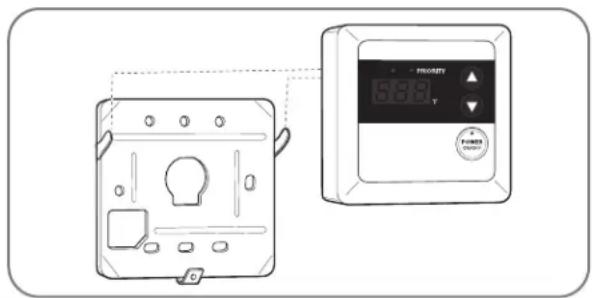
| Remote Control Model Number | Remote Control Description | Temperature Set Point Range Availability | |
| UMC-117 MAIN | 100^ - 120^ ( 38^ - 49^ ) | Factory Default | |
| 125^ - 140^ ( 52^ - 60^ ) | Adjustment for Residential Products | ||
| USC1-117 | BATH 1 | 100^ - 120^ ( 38^ - 49^ ) | Optional (Sold Separately) |
| USC2-117 BATH 2 | 100^ - 120^ ( 38^ - 49^ ) | Optional (Sold Separately) | |
| MIC-6 or MIC-185** Manifold System | Manifold System Optional | (Sold Separately) |
**When a manifold system is installed, the main remote control connected to the manifold controller (MIC-6 or MIC-185) has priority over the remote controls connected to the water heater.
INSTALLATION INSTRUCTIONS

Remote Control Installation (Outdoor Models)
WARNING:
Field wiring connections and electrical grounding must comply with local codes or, in the absence of local codes, with the latest edition of the National Electrical Code, ANSI/NFPA 70, or in Canada, Canadian Electrical Code, CAN/CSA C22.1, Part 1.
NOTICE:
Remote control cable needs to be type CL3R/CMR shielded security wire equivalent (18 AWG) and need not to be polarity-sensitive.
It is not recommended to have wiring exposed.
DO NOT apply sealant to remote control cable.
DO NOT use network cable, telephone wire, or any twisted-pair cable.
Connecting the MAIN (UMC-117) Remote Control to a Wall:

natural_image
Diagram showing a tool applying material to a square component, with no visible text or symbolsDrill a 1- to 1 1/2-in. (2.5/3.8-cm) hole at the proposed control location. Install the remote control cable between the location of the remote control and the water heater.

Remove the remote control from the base plate.
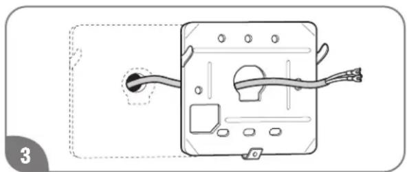
natural_image
Diagram of a device with wires and connectors, no text or symbols presentFeed the remote control cable through the large center hole in the base plate.

natural_image
Diagram of a device with labeled components and wiring, no readable text or symbols presentInstall the base plate to the wall using suitable screws and wall anchors.
NOTICE:
The tabs on the base plate should always point out.

natural_image
Diagram of an electronic device showing internal components and wiring (no text or symbols)Connect the remote control to the remote control cable.
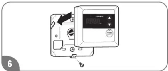
Position the remote control on the base plate.
NOTICE:
The tabs on the base plate should line up with the slots on the back of the remote control.
Secure the remote control to the base plate with one screw into the bottom tab.
NOTICE:
DO NOT attempt to connect the remote control or control wire to the water heater while the water heater has power applied to it. Damage to the water heater will occur. DO NOT cut or strip the wiring while it is connected to the water heater or while the water heater has power applied to it.
INSTALLATION INSTRUCTIONS

Remote Control Installation (Outdoor Models Only)
Remote Control Installation (cont.)
Connecting the Remote Control to the Water Heater:

Ensure that the power to the water heater has been disconnected.

natural_image
Technical diagram of an internal server or computer unit with visible internal components and directional arrows indicating flow or movement (no text or symbols present)Remove the front cover panel on the water heater.
NOTICE:
DO NOT connect remote control to power supply. The remote control connectors are located on the right side of the PCB.

natural_image
Technical line drawing of a robotic arm with visible wiring and components (no text or symbols)Connect the remote control extension cables from the remote control to the remote control connection terminals.
NOTICE:
The remote control wire connection terminals are not polarity-sensitive.

natural_image
Close-up of a hand using a wrench to adjust mechanical components (no visible text or symbols)Firmly tighten the terminal screws by hand.

Reinstall the front cover panel on the water heater.
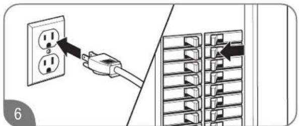
Switch on the power supply to the water heater. Check for proper operation of the remote control and the water heater.
INSTALLATION INSTRUCTIONS

WiFi Remote Circulation (Certain Models Only)
NOTICE:
Wifi remote must be installed Indoors.

natural_image
Line drawing of a screwdriver tip with a circular head, no text or symbols presentDrill a 1- to 1 1/2 in. hole at the proposed control location. Run the control cable between the

natural_image
Technical line drawing of a device with a rectangular casing and a vertical control panel (no text or symbols).retach, tawent, knad over the wind display and snap it in to secure.

Install the base of the wall mount to the wall using 2 included screws.

natural_image
Close-up of a computer motherboard with visible circuitry and connectors (no readable text or symbols)Plug the other end of the cable into the PCB of the water heater, which will be indoors.

Install the wifi display into the wall mount by resting the bottom tab into the slot on the wall mount. Then push the top tab of the wifi display into the retention clips and connect the wire harness.
INSTALLATION INSTRUCTIONS

Insulation Blankets
In general, insulation blankets for external use on gas water heaters are not necessary. The purpose of an insulation blanket is to reduce the standby heat loss from the water heater's storage tank. Since these water heaters do not store water, they eliminate the need for the insulation blanket.
WARNING:
NEVER cover the air inlet, flue outlet, or operating and warning labels attached to the water heater. Covering these components will cause dangerous operating conditions that can lead to death, personal injury, property damage, and/or product damage.
The manufacturer's warranty does not cover any damage or defect caused by insulation, insulation attachment, or use of any type of energy-saving or other unapproved devices (unless authorized by the manufacturer). The use of unauthorized energy-saving devices can result in death, personal injury, and/or property damage. The manufacturer disclaims any responsibility for such loss or injury resulting from the use of such unauthorized devices.

Installation Precautions
Follow all installation instructions covered in this manual.
Check the inlet gas pressure to make sure it is within the range specified on the rating plate.
Make sure there is adequate air for combustion and ventilation as described on "Venting" in this manual.
Maintain proper clearances to combustibles and non combustibles as specified on the rating plate.
Make sure the venting system complies with local codes, National Fuel Gas Codes (ANSI Z223.1/NFPA 54) or CAN/CSA B149.1, and the guidelines found on "Venting" in this manual.
Contact the local gas company to make sure the gas meter and gas piping are adequately sized.
Use Teflon tape on all male water line connections and fittings.
DO NOT block or restrict any air intake openings.
DO NOT remove the front cover unless absolutely necessary. This should only be done by a qualified service technician.
DO NOT install this product where standing water may occur.
DO NOT use pipe dope on water line connections and fittings.
INSTALLATION INSTRUCTIONS

Installation Checklist
A. Water Heater Location
☐ Indoor water heaters must be installed indoors.
☐ Outdoor water heaters must be installed outdoors.
☐ Close to area of ventilation termination (indoor models).
☐ Protected from freezing temperatures.
☐ Proper clearance from combustible material observed.
☐ Sufficient fresh air supply for proper operation of water heater.
☐ Air supply free of corrosive elements and flammable vapors.
☐ Provisions made to protect area from water damage.
Sufficient room to service heater.
□ Combustible materials, such as clothing, cleaning materials, and rags, clear of the heater and vent piping.
Water heater is properly attached to the wall.
B. Coaxial Vent (Indoor Models)
☐ Vent pipe material is Category III and is manufacturer-approved.
☐ Horizontal vent runs have 1/4 in. per foot of DOWNWARD slope towards the vent terminal.
☐ Vertical venting is installed as described in the "Vertical Vent Installation" section.
☐ Connector(s) securely fastened together with high-temperature silicone (500°F [260°C]) and airtight.
☐ All coaxial vent runs are properly installed.
☐ Vent terminal is properly installed.
☐ Maximum vent length is observed.
C. Water Supply/Relief Valve
Water supply has sufficient pressure.
Air has been purged from the water heater and the piping.
Water connections tight and free from leaks.
Water filter is clean and in place.
☐ All piping has been assembled as described on "Water Supply".
☐ Water pipes are insulated and protected from freezing, if necessary.
☐ Pressure-relief valve properly installed with discharge line running to open drain.
☐ Discharge line protected from freezing, if necessary.
D. Gas Supply
Gas type matches listing on rating plate.
☐ Gas supply pressure is sufficient for the water heater.
Gas line equipped with shut-off valve, union, and sediment trap as described on "Gas Supply System".
☐ Approved pipe-joint compound has been used on all gas pipe connections.
☐ All connections and fittings have been checked for leaks with a soapy water solution.
Gas company inspected installation (if required).
E. Electrical Wiring
Supply cord and/or wiring meets all local codes, National Electrical Code, ANSI/NFPA 70, in the U.S., or Canadian Electrical Code, CAN/CSA C22.1, Part 1, in Canada.
Voltage matches listing on rating plate.
Water heater is properly grounded.
F. Condensate
Drain hose is attached to the condensate collector, and condensate is drained as described on "Draining Vent Condensate".
USING YOUR WATER HEATER

Activating the Water Heater
WARNING:
Before operating this water heater, be sure to read and follow the instructions on the following label, all labels on the water heater, and the “Important Safety Information” section in this manual. Failure to do so can result in unsafe operating conditions that can result in death, personal injury, property damage, and/or product damage.
NOTICE:
If you have any problems reading or following the instructions in this manual, STOP and call a qualified service technician or contractor.
WARNING : If you do not follow these instructions exactly, a fire or explosion may result causing property damage, personal injury or loss of life.
A. This appliance does not have a pilot. It is equipped with an ignition device which automatically lights the burner. Do not try to light the burner by hand.
B.BEFORE OPERATING smell all around the appliance area for gas. Be sure to smell next to the floor because some gas is heavier than air and will settle on the floor. WHAT TO DO IF YOU SMELL GAS
- Do not try to light any appliance. -Do not touch any electric switch; do not use any phone in your building. -Immediately call your gas supplier from a neighbor's phone. Follow the gas supplier's instructions. -If you cannot reach your gas supplier, call the fire department. -Do not return to your home until authorized by the gas supplier or fire department.
C. Use only your hand to push in or turn the gas control knob. Never use tools. If the knob will not push in or turn by hand, don't try to repair it, call a qualified service technician. Force or attempted repair may result in a fire or explosion.
D.Do not use this appliance if any part has been under water. Immediately call a qualified service technician to inspect the appliance and to replace any part of the control system and any gas control which has been under water.
OPERATING INSTRUCTIONS
1.STOP! Read the safety information above on this label.
2. Turn off all electric power to the appliance.
3.Do not attempt to light the burner by hand.
4. Turn the Gas Shutoff Valve located on the outside of the unit clockwise to the "OFF" position.
5. Wait five (5) minutes to clear out any gas. If you then smell gas, STOP! Follow "B" in the safety information above on this label. If you don't smell gas, go to the next step.
6. Turn the Gas Shutoff Valve located on the outside of the unit counterclockwise to the "ON" position.
7. Turn on all electric power to the appliance.
8. If the appliance will not operate, follow the instructions "To Turn Off Gas To Appliance" and call your service technician or gas supplier.
GAS SHUTOFF
VALVE


OPEN CLOSE
TO TURN OFF GAS TO APPLIANCE
- Turn off all electric power to the appliance if service is to be performed.
- Turn the Gas Shutoff Valve located on the outside of the unit clockwise to the "OFF" position.
USING YOUR WATER HEATER

Operating Instructions
Read, understand, and follow the safety information listed on the operating label and in the "Important Safety Information" section in this manual.
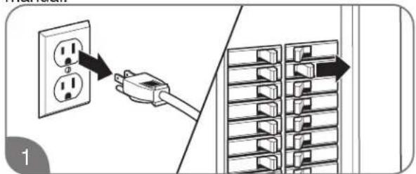
Disconnect all electric power to the water heater.

natural_image
Technical diagram of a mechanical assembly with pipe fittings and a gear mechanism (no text or symbols)Turn the gas shut-off valve clockwise to the OFF position. This valve is located on the outside of the water heater. Wait 5 minutes to clear any gas. If you don't smell gas, proceed to Step 3.
NOTICE:
If you smell gas, STOP and follow the safety instructions listed under B on the operating label or on the front cover of this manual.
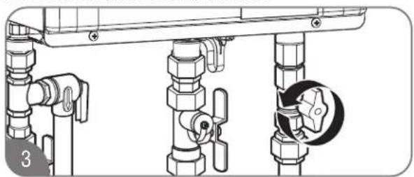
natural_image
Technical line drawing of a piping assembly with valve fittings and a close-up inset showing a circular component (no text or symbols)Turn the gas shut-off valve counterclockwise to the ON position.

Turn on all electric power to the water heater. The remote control must be powered on prior to operating the water heater.
WARNING:
DO NOT attempt to light the burner by hand. Lighting the burner by hand is an unsafe operating condition that can result in death, personal injury, property damage, and/or product damage.
If the water heater burner will not light, turn off the water heater as described below and call your service technician or gas supplier.
Shutting Off the Water Heater

Disconnect all electric power to the water heater.
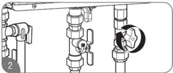
natural_image
Technical diagram of a pipe valve assembly with a close-up view showing a rotary knob (no text or symbols present)Turn the gas shut-off valve clockwise to the OFF position.
USING YOUR WATER HEATER

Safety Precautions
WARNING:
- Flammable vapors can be drawn by air currents from surrounding areas to the water heater. Vapors can ignite causing death, personal injury, or product damage.
-
DO NOT store or use flammable or combustible materials (gasoline, paint thinner, adhesives, newspapers, rags, mops, etc.) in the vicinity of the water heater or any other gas appliance. If they must be used, open doors and windows for ventilation, and shut off all gas-burning appliances, including their pilot lights.
-
DO turn off manual gas shut-off valve if water heater has been subjected to overheating, fire, flood, physical damage, or if the gas supply fails to shut off.
- DO NOT turn on water heater unless water and gas supplies are completely opened.
- If there is any difficulty in understanding or following the operating and care instructions in this manual, it is recommended that you contact a qualified service technician to perform the work.

Setting the Water Temperature
DANGER:
Water temperatures above 125^ F ( 52^ C) will result in death and/or severe burns from scalding.
Safety and energy conservation are factors to be considered when selecting the water temperature setting. The temperature of the water in the water heater can be regulated by setting the temperature on the front of the remote control. Be sure to read and follow the warnings outlined on the pictured label.
The remote control has been preset and shipped at the recommended temperature setting.
Safety factors should be considered whenever altering the water temperature setting. The chart below may be used as a guide in determining the proper water temperature for your home.
Time/Temperature Relationship in Scalds
| Water Temperature | Time to Produce a Serious Burn |
| 120°F (49°C) | More than 5 minutes |
| 125°F (52°C) | 1 1/2 to 2 minutes |
| 130°F (54°C) | About 30 seconds |
| 135°F (57°C) | About 10 seconds |
| 140°F (60°C) | Less than 5 seconds |
| 145°F (63°C) | Less than 3 seconds |
| 150°F (66°C) | About 1 1/2 seconds |
| 155°F (68°C) | About 1 second |
Table courtesy of Shriners Burn Institute
! DANGER

Water temperature over 125^ F ( 52^ C) can cause severe burns instantly or death from scalds.
Children, disabled and elderly are at highest risk of being scalded.
See instruction manual before setting temperature at water heater.
Feel water before bathing or showering.
Temperature limiting valves are available, see manual.
USING YOUR WATER HEATER

Setting the Water Temperature (cont.)
Maximum water temperature occurs while the water heater burner is on. To determine the water temperature:

natural_image
Line drawing of a kitchen sink with three washers and a handle (no text or symbols)Turn on the hot water faucet and place a thermometer in the water stream.
NOTICE:
Water temperature at the faucet may vary depending on the season and the length of pipe from the water heater.
The control temperature range is between 100°F (38°C) and 120°F (49°C). To adjust the temperature to a desired setting, press the UP or DOWN adjustment button on the face of the control. The new temperature set point will show on the LED display.
NOTICE:
The temperature set point on the standard remote control cannot be increased above 112°F (44°C) when a hot water faucet is in the open position. To achieve temperatures above 120°F (49°C), contact a qualified service technician. Only factory-authorized remote control(s) should be used.
The water heater may not operate with a small water flow (<0.4 gpm). Increase the water flow and recheck. If it still does not operate with the hot water faucet completely open, increase the temperature setting on the remote control.
Water Heater Facts
DANGER:
Water temperatures above 125°F (52°C) will result in death and/or severe burns from scalding.
- The hottest-temperature water will be at the faucet closest to the water heater.
- Always remember to test the water temperature with your hand before use.
• Always supervise young children or others who are incapacitated. - The water heater is equipped with a device that will shut off the gas supply to the burner if the water heater exceeds normal operating temperatures.
- Any water heater that has been subjected to fire, flood, physical damage, or been under water should be turned off at the manual gas shut-off valve and not used until it has been checked by qualified service personnel.

USING YOUR WATER HEATER

Setting the Water Temperature
WARNING:
Improper adjustment, alteration, service, or maintenance can result in death, personal injury, property damage, and/or product damage.
Maximum Temperature Adjustment by the Main Display Control (UMC-117)
DANGER:
Water temperatures above 125°F (52°C) will result in death and/or severe burns from scalding.
WARNING:
Refer to chart below and the scald potential warnings on page 4 on this manual before making an adjustment. Changing this setting is done at your own risk.
Time/Temperature Relationship in Scalds
| Water Time to Produce Temperature a Serious Burn | |
| 120°F (49°C) | More than 5 minutes |
| 125°F (52°C) | 1 1/2 to 2 minutes |
| 130°F (54°C) | About 30 seconds |
| 135°F (57°C) | About 10 seconds |
| 140°F (60°C) | Less than 5 seconds |
| 145°F (63°C) | Less than 3 seconds |
| 150°F (66°C) | About 1 1/2 seconds |
| 155°F (68°C) | About 1 second |
Table courtesy of Shriners Burn Institute
Residential water heater temperatures can be adjusted up to 140^ F ( 60^ C). DO NOT perform the following adjustment if a setting of up to 140^ F ( 60^ C) is not required.
| Temperature Conversion Chart °F/°C | ||||||||
| 100 | 102 | 104 | 106 | 108 | 110 | 112 | 114 | 116 |
| 38 | 39 | 40 | 41 | 42 | 43 | 44 | 46 | 47 |
| 118 | 120 | 125 | 130 | 140 | 150 | 160 | 170 | °F |
| 48 | 49 | 52 | 54 | 60 | 66 | 71 | 77 | °C |
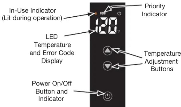
To adjust the set temperature above 120^ F ( 49^ C), please refer the following steps.

natural_image
Hand pressing a button on a black rectangular device (no text or symbols visible)Turn on the control.

natural_image
Technical diagram showing pipe fittings and valve assembly (no text or labels)Turn off the gas and water to the water heater by closing the shut-off valves.

Press the UP adjustment button repeatedly until 120^ F ( 49^ C) shows in the LED display. Hold the UP button until the “120” on the display starts to blink.
NOTICE:
LED display only shows °F.
USING YOUR WATER HEATER

Setting the Water Temperature
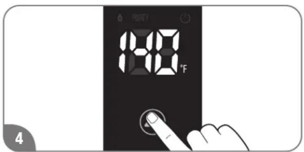
While "120" is blinking, press and hold the UP button for 5 seconds, to set ever above 120^ , should press and hold the UP button for 5 seconds.
Setting with Remote Control

To change the temperature settings up to 140°F (60°C):

Turn on the remote control.
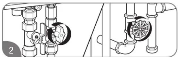
natural_image
Technical diagram showing pipe fittings and valve assembly (no text or labels)Turn off the gas and water to the water heater by closing the shut-off valves.
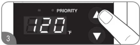
Press the UP adjustment button repeatedly until 120^ F ( 49^ C) shows in the LED display. Hold the UP button until “140” on the display starts to blink and continue holding the UP button.
NOTICE:
LED display only shows °F.

While "140" is blinking, press the UP and DOWN adjustment buttons at the same time. "140" will appear without blinking
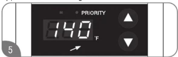
Press the UP or DOWN adjustment button to set the desired temperature.

natural_image
Diagram showing pipe valve installation and wheel switch mechanism (no text or labels)Turn on the gas and water to the water heater by opening the shut-off valves.
To limit maximum water temperature setting to 120^ F ( 49^ C):
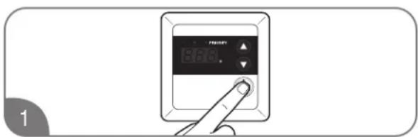
Turn on the remote control.
USING YOUR WATER HEATER

Setting the Water Temperature
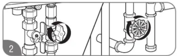
natural_image
Technical diagram showing pipe fittings and valve mechanism (no text or symbols)Turn off the gas and water to the water heater by closing the shut-off valves.

Press the DOWN adjustment button repeatedly until 100^ F ( 38^ C) or shows in the LED display. Hold the DOWN button until the number on the display starts to blink.

While the number is blinking, press the UP and DOWN adjustment buttons at the same time. The number will stop blinking.
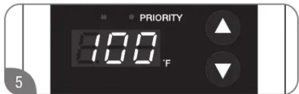
Press the UP or DOWN adjustment button to set the desired temperature.

natural_image
Diagram showing pipe valve installation and cooling mechanism (no text or symbols)Turn on the gas and water to the water heater by opening the shut-off valves.

WiFi Setup
- Download the EcoNet app to your mobile device and ensure that the device is connected to the WiFi network.
- Press and hold the WiFi button 📷 on the display until the WiFi indicator 📤 begins flashing.
- Open the EcoNet application and follow the instructions on the application to connect the water heater.
USING YOUR WATER HEATER

Piping for Space Heaters
Local codes or plumbing authority requirements may vary from the instructions or diagrams provided in this manual and take precedence over these instructions.
Combination Potable and Space Heating Application
DANGERS:
When this system requires water for space heating at elevated temperatures (above 125^ F [52°C]), a mixing or tempering valve must be installed in the hot water supply line to the house in order to reduce the scald hazard potential.
- Any piping or components used in the installation of this water heater in a combination potable and space heating application must be suitable for use with drinking water.
- If this water heater is installed in an application intended to supply domestic hot water needs and hot water for space heating purposes, DO NOT connect the heater to an existing heating unit or components of a heating system that have previously been used with a nondrinking water system. Toxic chemicals such as those used for boiler treatment may be present and will contaminate the drinking water supply causing possible health risks. Never introduce toxic chemicals, such as those used for boiler treatment, into this system.
- This water heater is not approved as the dedicated space heating unit. This water heater must be used for combination applications with air handler only and not for indoor heating applications.
Typical Combination Illustration

USING YOUR WATER HEATER

Recirculation Pump Control
Local codes or plumbing authority requirements may vary from the instructions or diagrams provided in this manual and take precedence over these instructions.
Recirculation Mode
Your tankless water heater has the ability to control an external recirculation pump which recirculates the water in the plumbing system to provide hot water more quickly when a faucet is opened.
Two modes are available:
- Timer recirculation (Energy Saver Mode)
- Timer recirculation (Performance Mode)
If this water heater has wifi capability, additional two modes are available:
- On-Demand recirculation
- Schedule recirculation
Information for setting up these modes can be found in the EcoNet App.
NOTICE:
Recirculation control is for residential application only. Recirculation control cannot be used with an air handler or with multiple water heater installations. The maximum temperature setting is 140^ F ( 60^ C) in recirculation control.
Pump Requirements
Voltage: 120V, 60Hz
In-rush current: Less than 2.5 amps
Amperage: less than 2.0 amps
WARNING:
A control board can be damaged if amperage exceeds 2.0 amps.
Pump Size
The pump should be sized for about 2.5 gpm at the pressure drop through the tankless water heater and the supply and return plumbing in the recirculation loop. Contact service department listed on page 77 of this use and care manual if you need more information.
Recommend size and length for recirc. line
To conserve energy and minimize heat loss, insulation for hot water lines is recommended.
*Equivalent pipe length includes hot water line, return lines and all fittings.
| Maximum allowable equivalent pipe Length* | ||
| Pipe Diameter(Copper pipe) | 34 ” 12 ” | |
| Pipe length 400 | ft. 100 ft. | |
Typical Recirculating Pump Installation

flowchart
graph TD
    A["Single Unit"] --> B["Expansion Tank"]
    B --> C["Cold Water Supply"]
    B --> D["Circulation Pump"]
    D --> E["Dedicated Return Line"]
    D --> F["Hot Water Loop"]
    F --> G["Hot Water to Fixtures"]
    G --> H["3/4*"]
    H --> I["3/4*"]
    I --> J["Circulation Pump"]
    J --> K["Wire to Connect to Pump"]
    K --> L["Cold Water to Tankless"]
    L --> M["Cold Water Supply"]
USING YOUR WATER HEATER

Recirculation Pump Control
Installation

Disconnect all electric power to the water heater.

natural_image
Technical line drawing of a mechanical device with ports and components (no text or symbols)Remove the front cover panel on the water heater.
Install the recirculation pump on the return line according to the pump manufacturer installation instructions. Install a check valve in the return line as shown in typical recirculation pump installation if one is not integrated into the pump. See "Typical Recirculation Pump Installation".
* Check valve is included in Rheem recirculation pump kit.


The wire harness for the recirculation pump is bundled with the wire harness from the control board. Find a blue connector with a black and a white wire.
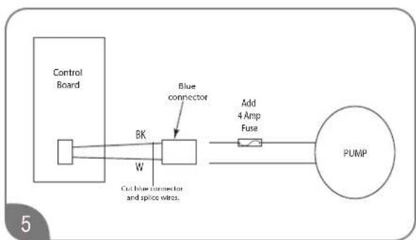
flowchart
graph LR
    A["Control Board"] --> B["BK"]
    B --> C["Blue connector"]
    C --> D["PUMP"]
    D --> E["Add 4 Amp Fuse"]
    E --> F["Cut blue connector and splice wire"]
    style A fill:#f9f,stroke:#333
    style B fill:#ccf,stroke:#333
    style C fill:#cfc,stroke:#333
    style D fill:#fcc,stroke:#333
    style E fill:#ffc,stroke:#333
    style F fill:#cff,stroke:#333
Connect the pump's connector to the control board harness. If necessary, cut the blue connector, splice the wires, and add a 4 amp fuse to the hot wire of the pump.

Connect the ground wire from the pump to a screw at the base of the water heater cabinet.
NOTICE:
Follow any applicable electrical code and the pump manufacture installation instruction referring to the Pump Electrical Connection Diagram in Step 5 of these instructions.

Find DIP Switch 2 in the top-right portion of the control board. The switch labeled "DIP 2" is the bottom switch.
USING YOUR WATER HEATER

Recirculation Pump Control

The factory setting for this switch should all be in the OFF position (DOWN).

Change the first switch on "DIP 2" to the ON position (UP). Performance mode is selected.

To select Energy Saver mode, change the fourth switch on "DIP 1" to the ON position (UP).

natural_image
Technical line drawing of an internal combustion chamber with labeled components (no text or symbols)Replace the front cover panel.

natural_image
Illustration of a finger pressing a button on a dark surface, no text or symbols presentTurn on all electric power to the water heater.
Turn On the remote control. The pump and water heater will turn on to raise recirculation loop temperature.
Recirculation Operation
The water heater is turned ON when the recirculation pump starts operation. The water heater produces hot water at the setting temperature. When the return water temperature reaches approximately 15^ F ( 8^ F) below the setting temperature, the water heater and the pump will turn OFF. The cycle will restart at the approximate time interval in the table below based on the temperature thermistor readings.
Energy Saver Mode
The Energy Saver mode operates as follows:
- Less energy consumption due to fewer pump cycles
- Pump cycles ON every 30 to 69 minutes
Performance Mode
The Performance mode operates as follows:
- Higher energy consumption due to more pump cycles
- Pump cycles ON every 15 to 35 minutes
| Setting Temp Typical Pump ON Intervals [Min] | ||
| [°F] Performance Energy Saver | ||
| 140 15 30 | ||
| 135 15 30 | ||
| 130 15 30 | ||
| 125 15 30 | ||
| 120 16 31 | ||
| 118 17 33 | ||
| 116 18 35 | ||
| 114 19 38 | ||
| 112 20 40 | ||
| 110 22 44 | ||
| 108 24 47 | ||
| 106 26 51 | ||
| 104 28 56 | ||
| 102 31 62 | ||
| 100 35 69 | ||
Actual pump ON intervals may vary based on the setting temperature, insulation, and heat loss in the system.
USING YOUR WATER HEATER

Recirculation Pump Control
Recirculation Operation – On-Demand mode-
If the On-Demand mode is used, the water heater needs wifi capability.
If the water heater is NOT a WiFi model, you cannot use the On-Demand mode.
To enter On Demand Mode
- Ensure Switch 1 on DIP 2 and switch 4 on DIP 1 are off.
• In less than one minute. - Turn Switch 1 on DIP 2 on-off-on-off.
- Press the Adjust Button
• The LED will flash one time
The unit is now in on demand mode.
NOTE:
If the water heater does not have WiFi capability, the built-in display needs to be replaced to the display including wifi capability.
Rheem offers the display including wifi capability.
See the Parts and Accessories catalog for more information.
When set to On-Demand mode, the recirculation pump is ON for 5 minutes when the water heater receive the signal form the application on smart phone.
Mode setting – On-Demand mode-
Please refer to the instruction of WiFi display section.
Recirculation Operation – Schedule mode-
If the Schedule mode is used, the water heater needs wifi capability.
If the water heater is NOT a WiFi model, you cannot use the Schedule mode.
NOTE:
If the water heater does not have WiFi capability, the built-in display needs to be replaced to the display including wifi capability.
Rheem offers the display including WiFi capability.
See the Parts and Accessories catalog for more information.
When set to Schedule mode, the recirculation pump is ON according the setting schedule on the application on smart phone
Mode setting – Timer mode-
To use Schedule mode, the water heater should be set to Performance mode or Timer mode.
USING YOUR WATER HEATER

Water Saving Control
Water saving control is optional and is inactive as default. To activate this control, appropriate procedures must be followed.
Water saving control can reduce waste water at initiation of hot water demand by reducing flow until outlet hot water reaches set temperature.
It is recommended to turn ON this control if the water heater is installed in a drought area or anywhere water conservation is needed.
Follow the steps below to turn ON the water saving control.

natural_image
Technical diagram showing pipe fittings and valve assembly (no text or labels)Turn off the gas and water to the water heater by closing the shut-off valves.

natural_image
Technical line drawing of a mechanical device with mounting feet and internal components (no text or symbols)Remove the front cover panel on the water heater.
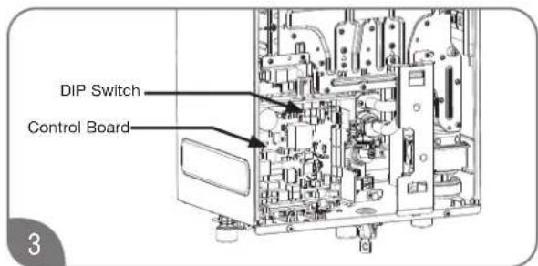
Find DIP Switch 1 located in the top-middle portion at the control board. The switch labeled "DIP 1" is the right-most set of switches. If any DIP switches are on for venting/altitude settings, switch them to the OFF position.

Change the third switch on "DIP 1" to the ON position (UP).
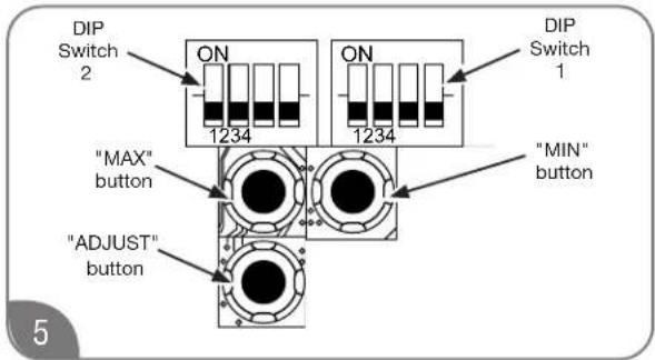
Press "Max button" or "Min button" on the control board to set the activation of this control.

LED display on the built-in control shows "oF".
Within 30 seconds of turning the third switch, press the "Max button" or "Min button" on the control board to set the activation of this control.
Within the next 30 seconds, the display/control board will show the water saving control setting. The LED identifications are below.
| WATER SAVINGCONTROL | CONTROL BOARDLED (RED) | DISPLAY LED |
| ON | Once Flashing | ON |
| OFF | Twice Flashing | OF |
USING YOUR WATER HEATER

Water Saving Control

After setting the activation of this control, change the third switch on "DIP 1" to the OFF position (DOWN). Be sure to reapply any venting/altitude DIP switch settings.

natural_image
Technical line drawing of an open industrial machine with internal components and piping (no text or symbols)Replace the front cover panel and turn the remote ON. Turn the remote on before turning the water supply on.

natural_image
Technical illustration of pipe fittings and valve assembly (no text or symbols)Turn on the gas and water to the water heater by opening the shut-off valves.
CARING FOR YOUR WATER HEATER

Water Heater Inspections
Venting System (Direct Vent Only)
The venting system should be inspected annually by a qualified service technician to ensure all of the vent sections are secure and airtight.
WARNING:
DO NOT operate the water heater if the vent system shows signs of leaking exhaust. Leaking exhaust could lead to death, personal injury, and/or product failure.

Check the air intake and vent outlet for blockage and/or debris.
Condensate Trap (Direct Vent Only)
CAUTION:
DO NOT operate without the condensate trap connected to the vent and routed to the proper drain. It could cause the system to malfunction or fail.
On a regular basis, inspect the condensate trap to ensure there is enough water in the trap and the condensate is draining properly.

natural_image
Technical line drawing of a mechanical device with no visible text or symbolsEnsure that condensate is disposed of per local codes and regulations.
CARING FOR YOUR WATER HEATER

Water Heater Inspections
Burner
It is recommended that the burner be inspected annually by a qualified service technician.
⚠️ DANGER:
Shock Hazard – Removing the front cover panel exposes you to live electricity. Electric shock will cause death or serious personal injury.

natural_image
Technical line drawing of a vertical industrial or mechanical device with labeled components (no text or symbols present)Remove 4 screws and the unit cover panel.

natural_image
Diagram of a kitchen sink with two washers and a handle, showing a circular dial indicator (no text or symbols)Turn on a hot water faucet.

While the water heater is operating, inspect the main burner flames through the burner sight glass. The flames should be blue when the main burner is firing.
NOTICE:
If the flames are not blue or you observe unusual burner operation, shut off the water heater and contact a qualified service technician.

natural_image
Technical line drawing of an internal appliance or enclosure with visible internal components and mounting brackets (no text or symbols)Turn off the hot water faucet and reinstall the unit cover panel.
CARING FOR YOUR WATER HEATER

Care and Cleaning
⚠️ DANGER:
Shock Hazard – Make certain power to the water heater is OFF before removing protective cover for any reason. Electric shock will cause death or serious personal injury.
WARNING:
Combustible materials, such as clothing, cleaning materials, or flammable liquids, must not be placed against or next to the water heater. Fire or explosion can occur causing death, personal injury, and/or product damage.
All care and cleaning to and around the water heater should only be performed with the water heater turned off and the electrical power supply disconnected.
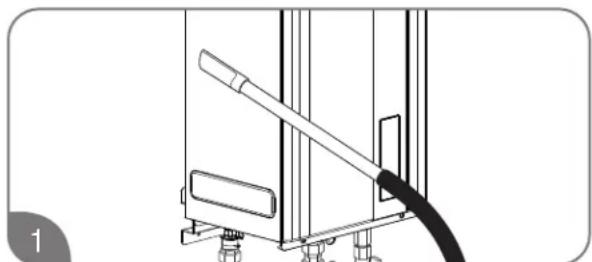
natural_image
Line drawing of a mechanical device with a cable and lever (no text or symbols)Vacuum around the water heater to remove any dust, dirt, and/or lint buildup.

natural_image
Line drawing of a hand cleaning or cleaning a window with a sponge (no text or symbols)Clean the water heater and the remote control with a damp soft cloth and mild detergent. Gently wipe and completely dry all surfaces.

Check the air intake and vent outlet for blockage and/or debris.
NOTICE:
The air intake requires a minimum of 12 in. (30 cm) of clearance between the air intake opening and any obstruction.
Clean the water filter monthly, as described below and on the next page.
Water Filter Cleaning
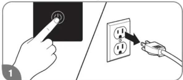
Turn off the water heater and disconnect the electrical power supply.

Turn off the water supply to the water heater.

Drain the water heater. See "Draining the Water Heater" Section.
CARING FOR YOUR WATER HEATER

Care and Cleaning
CAUTION:
DO NOT tap or force the filter during removal. This can deform and/or damage the filter.
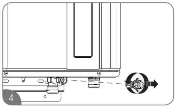
natural_image
Technical line drawing of a mechanical assembly with a circular component and directional arrow (no text or symbols)Unscrew the water filter from the base of the cold water inlet line and carefully slide it out of the line.
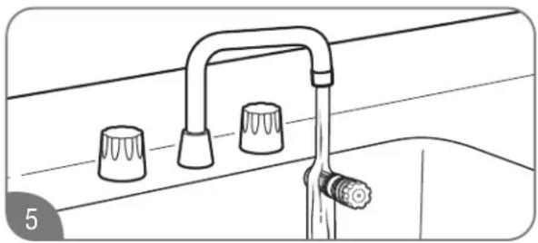
natural_image
Line drawing of a kitchen sink with three kitchen handles and a handle (no text or symbols)Clean the water filter under running water. To remove severe sediment and dirt, use a soft brush.
CAUTION:
DO NOT overtighten the water filter. Overtightening can deform and/or damage the filter.
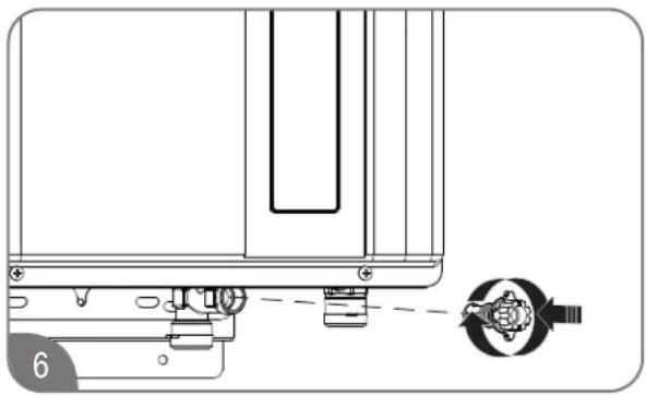
natural_image
Technical line drawing of a mechanical assembly with a close-up view of a component (no text or symbols)Replace the filter in the cold water inlet line and tighten until it is snug.

Turn on the water supply, reconnect the electrical supply, and turn on the water heater.
CARING FOR YOUR WATER HEATER

Preventive Maintenance
WARNING:
Failure to perform routine preventive maintenance can prevent the water heater from operating properly. Improper operation can cause carbon monoxide dangers, excessive water temperatures, and other potentially hazardous conditions resulting in death, personal injury, and/or product damage.
Properly maintaining your water heater will ensure dependable, trouble-free service.
User Preventive Maintenance
Establish and follow a routine preventive maintenance program. The following suggested items should be included in your program.

Monthly check and clean the water filter. See "Water Filter Cleaning" on this Use and Care Manual.
WARNING:
Hot water is released during manual operation of the relief valve. Make sure all people and animals are clear from the area before performing this check to prevent death, personal injury, and/or property damage from hot drain water.

Annually check the operation of the pressure-relief valve. Lifting the lever handle on the pressure-relief valve opens the valve to flush hot water through the discharge line to the drain. After several gallons have drained, release the lever handle to close the valve and stop draining.
NOTICE:
If the pressure relief valve on the hot water heater discharges periodically, this may indicate a problem in the water system. Contact the water supplier or a plumbing contractor to correct the problem. DO NOT plug the relief valve outlet.

natural_image
Pure technical diagram of piping and a mechanical component with no text or symbols- Inspect and keep the area around the water heater clear and free of flammable materials, such as gasoline and other flammable vapors and liquids.
- Visually inspect the water heater for damage and/or denting. If present, contact a service personnel to verify proper operation.
- Check for abnormal sound during normal operation (e.g., hissing or banging noises). Contact a qualified service technician or plumbing contractor.
- Check all gas and water pipes for leaks. See "Leak Testing" on this Use and Care Manual.
NOTICE:
- DO NOT operate the water heater if you feel something is wrong with the unit.
- DO NOT allow children to operate or handle the unit.
- After inspections, maintenance, and/or cleaning, ensure proper operation by turning on a hot water faucet.
Professional Preventive Maintenance
It is recommended that a periodic inspection of the water heater burner, relief valve, air intake filter, water filter, and venting system be made by a qualified service technician.
WARNING:
Certain water conditions can damage the water heater and may cause defects, malfunctions or failures of the water heater that are not covered by the limited warranty. See "Water Quality" on this Use and Care Manual.
CARING FOR YOUR WATER HEATER

Draining the Water Heater
WARNING:
Failure to follow these draining instructions can cause serious personal injury from scalding and/or product damage.

natural_image
Hand pressing a button on a black square surface, no text or symbols visibleTurn off the water heater by pressing the POWER ON/OFF button on the control panel.

natural_image
Technical diagram of a mechanical valve assembly with rotating components (no text or labels)Close the gas shut-off valve(s).
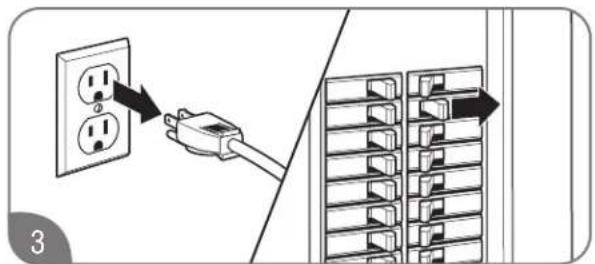
At least 10 seconds after Step 1, unplug the water heater or disconnect the power supply at the circuit breaker box.

natural_image
Diagram of a kitchen sink with two circular fixtures and a handle, no text or symbols presentOpen all hot water faucets. Run the water until it is COLD; then shut off the faucet.
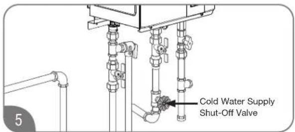
Close the water shut-off valve.

natural_image
Line drawing of a hand holding a curved pipe or tube, with no visible text or symbolsUsing a suitable container to catch the water, remove the water filter from the base of the cold water inlet line.

natural_image
Line drawing of a pipe system with a hose and circular drain component (no text or symbols)Connect a garden hose to the drain valve in the hot water outlet line and place the other end in a suitable drain. Open the drain valve until all the water has drained from the water heater. Leave water heater as is until placed back in service.
CARING FOR YOUR WATER HEATER

Draining the Water Heater (cont.)
CAUTION:
Even when drained properly, a small amount of water will remain in the water heater. In cold weather conditions, this water can freeze. If this happens, allow the defrost protection on the water heater at least 60 minutes to melt the frozen water. The water heater will not work properly until this water is thawed.
To put the water heater back in service:

natural_image
Diagram of a pipe valve with a rotating knob and connecting tubing (no text or symbols)Disconnect drain hose. Make sure the drain valve is closed.
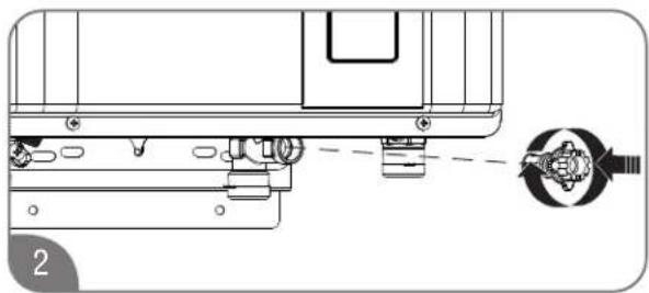
natural_image
Technical line drawing of a mechanical assembly with no visible text or symbolsReinstall the water filter in the base of the cold water inlet line.

natural_image
Technical diagram of pipe connections with a circular component, no text or symbols presentOpen the water shut-off valve.
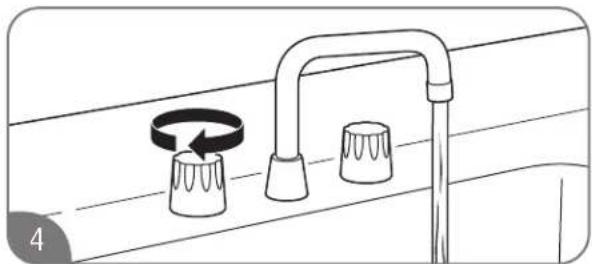
natural_image
Diagram of a kitchen sink with two circular switches and a handle, no text or symbols presentOpen all hot water faucets and let run until all air has been purged from the lines.
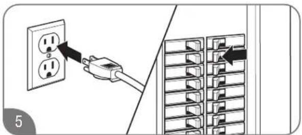
Plug in the power cord or reconnect the power supply at the circuit breaker box.

natural_image
Technical diagram of a piping system with valve fittings and a rotating knob (no text or symbols)Open the gas shut-off valve(s).

natural_image
Hand pressing a button on a black surface, no text or symbols visiblePress the POWER ON/OFF button on the control panel to restart the unit.
CARING FOR YOUR WATER HEATER

Draining the Water Heater (cont.)
Preferred Drain Method
Isolator valve kits may be purchased from the manufacturer, distributor, or place of purchase. The kits include two full port isolation valves to be used in the inlet and outlet water lines. It is highly recommended to install isolator valve kits because these kits provide a means for full diagnostic testing and ease of system flushing.
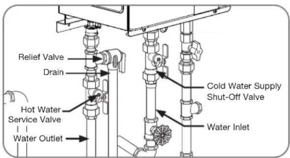

Freeze Protection
WARNING:
Failure to drain the water heater can cause serious personal injury from scalding and/or product damage.
Whenever the water heater may be exposed to freezing conditions, precautions should be taken to help prevent the water heater from freezing.
Freezing conditions come from the ventilation system on direct-vent models and from exposure to cold air on outdoor models.
All of these water heaters are equipped with a freeze protection electric heater. This heater helps prevent freezing inside the water heater down to outside temperature of -30^ F ( -35^ C) on indoor installations and approximately -4^ F ( -20^ F) on outdoor installations. These temperatures are all based on temperatures without wind.
The heater only protects the internal components of the water heater.
NOTICE:
Unplugging or disconnecting the power supply to the water heater will also disconnect the power to the heater.
External piping and valves require additional freeze protection. One method is to wrap insulation around the piping and valves.
Another method is to turn on a hot water faucet and leave a small amount of water running at a faucet. This will help protect the water heater, piping, and valves from freezing.
If power outages occur during freezing conditions, it is recommended to completely drain the water heater to help prevent damage to the unit. See "Draining the Water Heater." Once power is restored, refill the water heater and check for frozen or leaking components.
Components or heat exchangers damaged by freezing conditions is not covered under manufacturer's warranty.
Running Water Freeze Protection

natural_image
Hand pressing a button on a black surface, no text or symbols visibleTurn off the water heater by pressing the POWER ON/OFF button on the control panel.
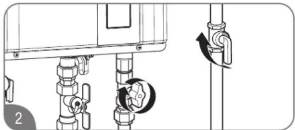
natural_image
Technical diagram of a piping system with valve and valve mechanism (no text or labels)Close the gas shut-off valve(s).

natural_image
Diagram of a kitchen sink with two circular switches and a handle, no text or symbols presentOpen a hot water faucet slightly until the water stream is approximately 1/8 in. (0.3 cm). Be sure to check the flow periodically.
CARING FOR YOUR WATER HEATER

Vacation and Extended Shutdown
WARNING:
Failure to drain the water heater can cause serious personal injury from scalding and/or product damage.
If the water heater is to remain idle for an extended period of time, the power and water to the heater should be turned off.
The water heater and piping should be drained if they might be subjected to freezing temperatures. When drained, some water may remain in the unit. See “Freeze Protection” section on this Use and Care Manual.
After an extended shutdown, the water heater's operation and controls should be checked by a qualified service technician.

Troubleshooting Chart
The information in the following troubleshooting chart may help you diagnose and/or fix a problem you may be experiencing. Please review this chart before calling for service assistance.
▲DANGER:
Shock Hazard – Make certain power to the water heater is OFF before removing protective cover for any reason. Electric shock will cause death or serious personal injury.
WARNING:
For Your Safety, DO NOT attempt repair of electrical wiring, gas piping, remote control, burners, vent connectors, or other safety devices. Refer repairs to a qualified service technician.
Problem Possible Cause Solution
Not enough or no hot water.

| 1. Unit is not ON. 1. Turn on the unit by pressing the POWER ON/OFF button. | |
| 2. Water shut-off valve is not completely opened. | 2. Check shut-off valve and open completely. |
| 3. Hot water faucet is not completely opened. | 3. Open hot water faucet completely. (The main burner goes off when incoming water volume is inadequate.) |
| 4. Water piping is frozen. 4. Allow piping to thaw. | |
| 5. Electrical power is disconnected or water supply is shut off. | 5a. Plug in the power cord or reconnect the power supply at the circuit breaker box.5b. Completely open the water supply valve. (Inadequate water volume will cause the main burner to turn off.) |
| 6. The temperature may be set too low. | 6. Increase the temperature setting. |
| 7. Mixing valve malfunctions (if applicable). | 7. Check and replace the mixing valve. |
| 8. Error code displayed on the remote control. | 8. See “Service Error Code Chart” on page 77. If required, contact a qualified service technician. |
| 9. Not enough water demand. 9. Increase the hot water flow at the faucet. | |
| 10. Water filter is clogged or dirty. | 10. Clean the water filter. (See pages 68 and 69.) |
| 11. Fixture aerator is clogged or dirty. 11. Clean the aerator. | |
| 12. Scale buildup in the heat exchanger. | 12. Check for error code. If required, contact a qualified service technician. |
| 13. Hot and cold water lines reversed. | 13. Reverse the water lines. |
CARING FOR YOUR WATER HEATER

Troubleshooting Chart (cont.)
| Problem Possible Cause Solution | ||
Water not hot enough. | 1. The temperature may be set too low. | 1. Increase the temperature setting at the remote control. |
| 2. The gas valve is not completely opened. | 2. Check and completely open the gas valve. | |
| 3. Gas supply pressure is low. | 3. Contact your gas utility company or gas contractor to verify the gas meter and gas piping size. | |
| 4. Bleed-over in one of the hot water fixtures. | 4. Contact a dealer or a qualified service technician. | |
Water too hot.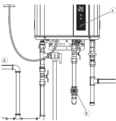 | 1. Temperature is set too high. | 1. Decrease the temperature setting at the remote control. |
| 2. Water shut-off valve is not completely opened. | 2. Check and completely open the water shut-off valve. | |
| 3. Small amount of water has been heated. | 3. Increase the hot water flow at the faucet to allow more water to flow through the water heater. | |
| Fan continues to rotate after the hot water faucet is closed. | The post-purge cycle clears flue gases. Normal operation. | |
CARING FOR YOUR WATER HEATER

Service Error Code Chart
Your water heater has an electronic diagnostic system built into it. When the water heater finds a problem, it displays an error code in the LED display on the remote control. The following chart lists the error codes along with their possible problem and solution. Using this chart may help you diagnose and/or fix a problem you may be experiencing. Please refer to this chart before calling for service assistance.
DANGER:
Shock Hazard – Make certain power to the water heater is OFF before removing protective cover for any reason. Electric shock will cause death or serious personal injury.
WARNING:
For Your Safety, DO NOT attempt repair of electrical wiring, gas piping, remote control, burners, vent connectors, or other safety devices. Refer repairs to a qualified service technician.
When an error code is displayed:

natural_image
Diagram of a kitchen sink with two circular switches and a curved pipe, no text or symbols presentTurn off all the hot water faucets.

natural_image
Hand pointing at a circular button with a power symbol, no text or labels presentTurn off the water heater by pressing the POWER ON/OFF button on the remote control.

Wait about 5 minutes; then restart the water heater by pressing the POWER ON/OFF button.

natural_image
Illustration of a kitchen sink with faucet and keyboard, showing hand pressing button (no text or symbols)Turn on a hot water faucet and recheck the remote control display.
If the error code remains in the display:
- Turn off the hot water faucet.
- Turn off the water heater.
- Unplug the water heater from power, wait about 30 seconds and plug back in.
-
Follow the error code chart information.
-
Restart the water heater, turn on a hot water faucet, and recheck the remote control display.
If the error code is still shown:
- Turn off the hot water faucet.
- Turn off the water heater.
- Make note of the displayed error code and call for service assistance. See "Call for Assistance" section on this Use and Care Manual.
NOTICE:
If the displayed error code is not listed in the chart, immediately turn off the water heater and call for service assistance.
CARING FOR YOUR WATER HEATER

Service Error Code Chart (cont.)
| Error Code Possible Cause Solution | ||
| 1L | Water heater has buildup of lime deposits. Contact a dealer or qualified service technician. | |
| 11 | The gas shut-off valve is not fully opened. Check shut-off valve and open completely. | |
| 12 | Gas service has been interrupted. Contact your gas utility company. | |
| LP gas is running low (LP models only). Refill or replace your LP gas container. | ||
| 14 | Water heater is overheating. Contact a dealer or qualified service technician. | |
| 31 | Faulty inlet thermistor. Contact a dealer or qualified service technician. | |
| 33 | Faulty outlet thermistor. | Contact a dealer or qualified service technician. |
| 61 | Faulty blower motor. | Contact a dealer or qualified service technician. |
| 66 | Faulty bypass motor. | Contact a dealer or qualified service technician. |
| P1 | Not enough water flow to operate the unit. Increase the water flow from the fixtures. | |
| 88 | Reminder of flushing the heat exchanger and/or replacing the water treatment filter. | Contact a dealer or qualified service technician. |
| 90 or 99 | Air intake or vent exhaust opening may be blocked. | Remove any blockage. (Air intake requires 12 in. [30 cm] of clearance.) |
| The vent pipes on the vent termination may not be connected properly. | Contact a dealer or qualified service technician. | |
IF YOU NEED SERVICE

Call for Assistance
- All questions, adjustments, repairs, and/or routine maintenance should be directed to your installer, plumbing contractor, or licensed service agent. If your contacts have moved or are not available, please refer to the telephone directory, commercial listings, or local utility company for qualified service assistance.
- If your problem has not been solved to your satisfaction, contact the Rheem National Service Department at the following address:
Rheem
National Service Department
800 Interstate Park Drive
Suite 700
Montgomery, AL 36109
Phone: 1-866-720-2076
When contacting the manufacturer, the following information will be requested:
A. Model and serial number. (See page 8 or the ratings plate on the side of the water heater.)
B. Address where the water heater is located.
C. Name and address of installation contractors (page 8) and all qualified service companies that have worked on the water heater.
D. Original installation date. (See page 8.)
E. Dates any service or preventive maintenance was performed.
F. Details of the persisting problem.
G. List of businesses that have tried to fix this problem, along with dates of service.
CARING FOR YOUR WATER HEATER

Maintenance Notice
Maintenance notice is an optional control and is inactive as default. Maintenance notice reminds users of water heater maintenance activities such as flushing the heat exchanger or replacing the water treatment filter (if applicable) in order to maximize the life of your tankless water heater. Contact technical service department listed on page 77 of this use and care manual if you are not familiar with these maintenance activities.

natural_image
Hand pressing a button on a black surface, no text or symbols visibleTurn off the remote control.

natural_image
Technical diagram showing pipe fittings and valve assembly (no text or labels)Turn off the gas and water to the water heater by closing the shut-off valves.

Press and hold the “▲” and “▼” button until “1Y” is displayed on the built-in display.
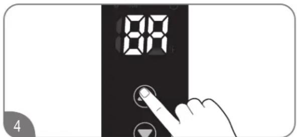
Press the “▲” or “▼” button until “8A” is displayed. And, press and hold the power button on the build-in display for 1 second.
The current setting time is displayed on the display.
(Factory setting is "OFF")

Press the “▲” or “▼” button to choose “50”, “75”, “100” or “OF”.
| Displayed Maintenance Notice Hour | |
| 50 500 hours | |
| 75 750 hours | |
| 100 1,000 hours | |
| OF OFF | |

natural_image
Technical diagram of a mechanical valve assembly with rotation arrows (no text or labels)Turn on the gas and water to the water heater by opening the shut off valves.
When tankless water heater has a certain number of hours of combustion, error code "88" is shown on the display. It is highly recommended to perform water heater maintenance activities such as flushing the heat exchanger and/or replacing the water treatment filter (if applicable).
CARING FOR YOUR WATER HEATER

Maintenance Notice
ERROR CODE 88 CLEARING IMPORTANT
It is highly recommended to perform water heater maintenance activities such as flushing the heat exchanger and/or replacing the water treatment filter (if applicable) before clearing this error code.
After these maintenance activities are completed, follow the steps below to clear error code "88".

natural_image
Hand pressing a button on a black surface, no text or symbols visibleTurn on the remote control.

natural_image
Technical diagram showing pipe fittings and valve mechanism (no text or symbols)Turn off the gas and water to the water heater by closing the shut-off valves.

Press the DOWN adjustment button repeatedly until the lowest setting temperature shows in the LED display.
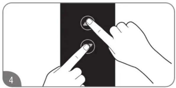
natural_image
Illustration of two hands pointing at a button on a black surface, no text or symbols presentPress and hold the DOWN and UP adjustment button for 5 to 10 seconds.
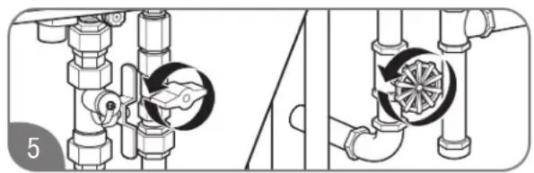
natural_image
Technical illustration of pipe fittings and valve assembly (no text or symbols)Turn on the gas and water to the water heater by opening the shut off valves.
If error code "88" is still shown, repeat steps 1 through 5 above.
IF YOU NEED SERVICE

Parts Ordering
WARNING:
For your safety, DO NOT attempt to disassemble, repair, or replace any portion of this unit. Refer all repairs, service, and/or adjustments to qualified service personnel.
Address all parts orders to the distributor or store where the water heater was purchased. All parts orders should include:
Direct-Vent Gas Components
- The model and serial number of the water heater from the rating plate.
- Specify the gas type (natural or LP) as marked on the rating plate.
- Parts description (as shown below) and number of parts desired.

| Ref # Description |
| 1 Front Cover Final Assembly |
| 2 Front Cover Screw |
| 3 Cabinet Bracket |
| 4 Power Cord |
| 5 Display/Controller |
| 6 Mounting Bracket Kit |
| 7 Blower Motor |
| 8 HEX Thermistor |
| 9 Hot Water Connection |
| 10 Drain Valve |
| 11 Hot Water Thermistor |
| Ref # Description | |
| 12 Water Control Valve | |
| 13 Inlet Water Connection | |
| 14 Water Filter | |
| 15 | Manifold/Gas Valve Kit |
| 16 | Manifold Screw |
| 17 | Gas Connection |
| 18 | Inlet Gas Screw |
| 19 | Control Board |
| 20 | Program Chip |
| 21 | Igniter/Flame Rod Kit |
| 22 Igniter Module | |
IF YOU NEED SERVICE

Parts Ordering
Outdoor Gas Components
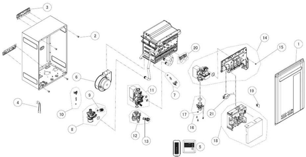
| Ref # Description |
| 1 Front Cover Final Assembly |
| 2 Front Cover Screw |
| 3 Cabinet Bracket |
| 4 Power Cord |
| 5 Display/Controller |
| 6 Blower Motor |
| 7 HEX Thermistor |
| 8 Hot Water Connection |
| 9 Drain Valve |
| 10 Hot Water Thermistor |
| 11 Water Control Valve |
| Ref # Description | |
| 12 Inlet | Water Connection |
| 13 Water Filter | |
| 14 Manifold/Gas Valve Kit | |
| 15 Manifold Screw | |
| 16 Gas Connection | |
| 17 Inlet | Gas Screw |
| 18 | Control Board |
| 19 | Program Chip |
| 20 | Igniter/Flame Rod Kit |
| 21 Igniter Module | |
LIMITED WARRANTY
For the RHEEM®, RUUD®, Richmond®, Paloma®, and EcoSmart® Residential Tankless Gas Water Heaters.
GENERAL
This Limited Warranty is only available to the original owner of the water heater at the original installation location. This Limited Warranty is not transferable.
Rheem Sales Company, Inc. (Rheem) warrants this tankless gas water heater, and its component parts, to be free from defects in materials and manufacture, under normal use and service, for the Applicable Warranty Period specified below. At its option, Rheem will repair or replace the defective water heater, or defective component part(s), in accordance with the terms of this Limited Warranty, if it fails in normal use and service during the Applicable Warranty Period. The replacement water heater must be manufactured by Rheem under one of the covered brand names. The replacement component part(s) must be Rheem authorized component part(s). The replacement unit will be warranted only for the unexpired portion of the original unit's Applicable Warranty Period.
Rheem strongly recommends that this tankless water heater be installed by a contractor that is licensed, state qualified and trained on Rheem's tankless products because improper installation may invalidate warranty coverage.
EFFECTIVE DATE
The Effective Date of warranty coverage (or the beginning of the Applicable Warranty Periods) is the date of the original installation of the water heater, if properly documented. Otherwise, it is the date of manufacture of the water heater plus ninety (90) days.
APPLICABLE WARRANTY PERIODS: The Applicable Warranty Period depends on the type of installation, as described below:
Residential: a Single Family Dwelling
Twelve (12) years from the Effective Date for the heat exchanger, five (5) years from the Effective Date for the component parts, and one (1) year from the Effective Date for certain labor as described under the heading, LABOR, SHIPPING AND PROCESSING COST.
Residential: a Single Family Dwelling used with Hydronic Force Air Heating
Ten (10) years from the Effective Date for the heat exchanger, five (5) years from the Effective Date for the component parts, and one (1) year from the Effective Date for certain labor as described under the heading, LABOR, SHIPPING AND PROCESSING COST. Provided that a Rheem manufactured/ Rheem approved potable water hydronic air handler is installed with the system.
Residential: a Single Family Dwelling with recirculation, controlled loop
Twelve (12) years from the Effective Date for the heat exchanger, five (5) years from the Effective Date for the component parts, and one (1) year from the Effective Date for certain labor as described under the heading, LABOR, SHIPPING AND PROCESSING COST. Provided that the recirculation system is an on demand type system or the pump is controlled with a temperature sensor (aquastat) and timer.
Residential: a Single Family Dwelling with recirculation, uncontrolled loop
Three (3) years from the Effective Date for the heat exchanger, three (3) years from the Effective Date for the component parts, and one (1) year from the Effective Date for certain labor as described under the heading, LABOR, SHIPPING AND PROCESSING COST, if the water heater is installed in a system in which the water is re-circulated using a continuously operating pump.
Commercial: any installation that is not a single family dwelling
Five (5) years from the Effective Date for the heat exchanger, five (5) years from the Effective Date for the component parts, and one (1) year from the Effective Date for certain labor as described under the heading, LABOR, SHIPPING AND PROCESSING COST.
Commercial: with recirculation, controlled loop
Five (5) years from the Effective Date for the heat exchanger, five (5) years from the Effective Date for the component parts, and one (1) year from the Effective Date for certain labor as described under the heading, LABOR, SHIPPING AND PROCESSING COST. Provided that the recirculation system is an on demand type system or the pump is controlled with a temperature sensor (aquastat) and timer.
Commercial: with recirculation, uncontrolled loop
Three (3) years from the Effective Date for the heat exchanger, three (3) years from the Effective Date for the component parts, and one (1) year from the Effective Date for certain labor as described under the heading, LABOR, SHIPPING AND PROCESSING COST, if the water heater is installed in a system in which the water is re-circulated using a continuously operating pump.
WARRANTY EXCLUSIONS
This Limited Warranty will not cover:
a) Damages, malfunctions or failures resulting from:
| Chart for Recommended Water Quality Levels | |||||||||
| pH (Total Dissolved Solids) TDS Free Carbon Dioxide (CO2) | Total Hardness | Aluminum | Chlorides | Copper | Iron | Manganese | Zinc | ||
| 6.5–8.5 | Up to 500 mg/L | Up to 15 mg/L | Up to 200 mg/L | 0.05 to 0.2 mg/L | Up to 250 mg/L | Up to 1.0 mg/L | Up to 0.3 mg/L | Up to 0.05 mg/L | Up to 5 mg/L |
Cited reference: National Secondary Drinking Water Regulations
- Installation of the water heater in environments in which water quality levels do not fall within the ranges listed in the table above:
b) Operating the water heater in a corrosive or contaminated atmosphere, including without limitation damages, malfunctions or failures caused by lime, mineral build-up, or scale.
c) Service trips to your business to teach you how to install, use, or maintain this water heater or to bring the water heater installation into compliance with local building codes and regulations or manufacturer's installation requirements.
d) Water heater unit installed for use in: spa or pool heating; a recreational vehicle; a boat or any other watercraft.
e) Water heater unit installed in any circulating system in which the temperature of the incoming water to the water heater is in excess of 140° f.
f) Water heater unit that is installed in any installation supplying radiant heat, such as in floor, baseboard, radiators, snow melt or closed loop systems, or any system using glycol or non-potable water.
g) Damages, malfunctions or failures resulting from failure to install the water heater in accordance with applicable building codes/ordinances or good plumbing and electrical trade practices.
h) Damages, malfunctions or failures resulting from improper installation or failure to operate and maintain the unit in accordance with the manufacturer's instructions.
i) Performance problems caused by improper sizing of the water heater or the gas supply line, the venting connection, combustion air openings, electric service voltage, wiring, or fusing.
j) Damages, malfunctions or failures caused by improper conversion from natural gas to LP gas or LP gas to natural gas fuel source.
k) Damages, malfunctions or failures caused by operating the water heater with any parts removed or with modified, altered, or unapproved parts installed.
I) Damages, malfunctions or failures caused by abuse, accident, fire, flood, freeze, lightning, acts of God and the like.
m) Heat exchanger failures (leaks) caused by operating the water heater in a corrosive or contaminated atmosphere or damages, malfunctions or failures caused by lime, mineral build-up, or scale.
n) Damages, malfunctions or failures caused by operating the unit at water temperatures exceeding the maximum setting of the operating, or high limit, control.
o) Heat exchanger failures caused by operating the water heater when it is not supplied with potable water, free to circulate at all times.
p) Damages, malfunctions or failures caused by subjecting the heat exchanger to pressures, or firing rates, greater than those shown on the rating label.
q) Damages, malfunctions or failures resulting from the use of any attachment, including any energy saving device, not authorized by Rheem.
r) Units installed outside the fifty states (and the District of Columbia) of the United States of America and Canada.
s) Units removed from the original installation location and reinstalled elsewhere.
t) Units that have had their rating labels altered, tampered with, or removed. A water heater should not be operated if the rating label is removed.
LABOR, SHIPPING, AND PROCESSING COSTS
For one (1) year after the Effective Date, Rheem will cover reasonable labor costs necessary to repair or replace a tankless water heater or component part that Rheem determines to be defective and covered by this Limited Warranty. The warranty service must be performed by a contractor that is licensed, state qualified, and trained to install and service Rheem's tankless water heaters. This Limited Warranty does not cover any labor expenses for general service, inspection, reinstallation, permits, removal and disposal of the failed water heater or defective component part(s), or updating the installation to meet manufacture or local code requirements. All such expenses are your responsibility.
Rheem will pay the transportation costs for an "in-warranty" replacement water heater, or "in-warranty" replacement component part(s), to a convenient delivery point (selected by Rheem) near the place the original water heater, or original component part(s), is located: such as a local water heater distributor. You must pay any local freight charges, including the cost of returning the failed water heater, or defective component part(s) to a convenient shipping location (selected by Rheem): such as a local Rheem distributor.
Rheem does not authorize, recommend, or receive any benefit from any claims processing or similar fees charged by others to process warranty claims for any water heater or component part(s). Rheem will not reimburse any party for these, or any other, fees not specifically covered in this Limited Warranty document.
HOW TO OBTAIN WARRANTY CLAIM ASSISTANCE
Any claim for warranty assistance must be made promptly. First, determine if your water heater is "in-warranty" (that is, within the Applicable Warranty Period). You can determine your unit's warranty status by adding its Applicable Warranty Period to its date of installation. However, if you do not have documentary proof of your water heater's date of installation, your unit's warranty status will be based on its date of manufacture as determined from the serial number. Add the Applicable Warranty Period plus ninety (90) days to the date of manufacture to determine whether the water heater is still covered by this Limited Warranty. You may also determine your unit's warranty status by obtaining the complete model number, complete serial number, and date of installation of your water heater and then accessing the "Warranty Verification" information on Rheem Water Heaters' internet website (www.rheem.com) or contacting Rheem's Claims Department (telephone (800) 621-5622) during normal business hours (in the Central Time Zone) to determine if the Applicable Warranty Period has expired. If your water heater is "in-warranty", contact the plumber, or mechanical contractor, that installed it for assistance with the warranty repairs, or replacement, required. Rheem Water Heaters' Technical Service personnel are available to assist you (by telephone at (866) 720-2076) in obtaining "in-warranty" service or to answer your questions about the operation or repair of your water heater during normal business hours (in the Central Time Zone). Be prepared to provide the plumber, mechanical contractor, or Rheem Technical Service person you call with the complete model number, the complete serial number, and the date of installation of your water heater in addition to an explanation of your water heater problem.
If an exact replacement is not available, Rheem will provide you with the current model of your water heater, or component part(s), or a replacement unit with comparable operating features. If government regulations or industry certification or similar standards require the replacement water heater, or replacement component part(s), to have features not found in the defective water heater, or the defective component part(s), you will be charged for the difference in price represented by those required features. If you pay the price difference for those required features and/or to upgrade the size and/or other features available on a replacement new water heater, you will also receive a complete new Limited Warranty (with the full Applicable Warranty Period) for the replacement new water heater.
Rheem reserves the right to inspect, or require the return of, the failed water heater or the defective component part(s). Each "in-warranty" failure water heater must be made available to Rheem (with the rating label and all the component parts intact) in exchange for the replacement water heater. Each defective "in-warranty" component part to be replaced must be returned to Rheem in exchange for the replacement component part.
Warranty compensation is subject to validation of "in-warranty" coverage by Rheem Claims Department personnel.
- To obtain warranty compensation for an "in-warranty" water heater failure, you must provide Rheem with the failed water heater (with the rating label and all the component parts intact) the complete model number and the complete serial number of the Rheem or Ruud water heater that replaced the failed unit; and the date the original water heater failed. You may also be required to provide documentary proof of the failed water heaters date of installation to establish its "in-warranty" status.
- To receive warranty compensation for an "in-warranty" defective component part, you must provide Rheem with: the defective component part; the complete model number and the complete serial number of the Rheem or Ruud water heater from which the defective component part was removed; and the date the defective component part failed. You may also be required to provide documentary proof of the date of installation of the Rheem or Ruud water heater from which the defective part was removed – or the date of purchase of the part (If it was purchased separately) – to establish the "in-warranty" status of the defective component part.
- If Rheem determines that the water heater or component part returned to Rheem is free of defects in material and manufacture and/or that it was damaged by improper installation or other cause not covered by this Limited Warranty, the warranty claim for the product, component part and/or labor may be denied. Warranty claim documentation should be mailed promptly to Rheem Water Heaters, Claims Department, 1241 Carwood Court, Montgomery, Alabama 36117, or in Canada, 125 Edgeware Rd. Unit 1, Brampton, ON, Canada L6Y 0P5
EXCLUSIVE WARRANTY - LIMITATION OF LIABILITY
THIS LIMITED WARRANTY IS THE SOLE AND EXCLUSIVE WARRANTY PROVIDED IN CONNECTION WITH THIS RHEEM®, RUUD®, RICHMOND®, PALOMA® AND ECOSMART® RESIDENTIAL TANKLESS GAS WATER HEATER UNIT (THE "WATER HEATER"). No one is authorized to make any other warranties on behalf of Rheem. ANY IMPLIED WARRANTIES, INCLUDING MERCHANTABILITY, OR FITNESS FOR A PARTICULAR PURPOSE, SHALL NOT EXTEND BEYOND THE APPLICABLE WARRANTY PERIODS, SPECIFIED PREVIOUSLY. RHEEM'S SOLE LIABILITY, WITH RESPECT TO ANY DEFECT, SHALL BE AS SET FORTH IN THIS LIMITED WARRANTY, AND ANY CLAIMS FOR INCIDENTAL OR CONSEQUENTIAL DAMAGES (INCLUDING DAMAGE FROM WATER LEAKAGE) ARE EXCLUDED. Some states do not allow limitations on how long an implied warranty lasts, or for the exclusion of incidental or consequential damages, so the above limitations or exclusions may not apply to you.
This Limited Warranty gives you specific legal rights, and you may also have other rights, which vary from state to state.
DO NOT RETURN THIS WATER HEATER OR PART TO RHEEM WITHOUT A RETURN AUTHORIZATION.
This document is for reference only and does not replace the original warranty document found in the back of the Use and Care manual provided with the tankless water heater.
DO NOT RETURN THIS DOCUMENT TO RHEEM.
KEEP IT WITH YOUR WATER HEATER OR BUSINESS RECORDS.
Name of Owner:
Owner's Address:
Name of Plumber/
Mechanical Contractor – Installer:
Address of Plumber/
Mechanical Contractor – Installer :
Telephone Number of Plumber/
Mechanical Contractor – Installer:
Date of Water Heater Installation:
Model Number of Your Water Heater:
Serial Number of Your Water Heater:
NOTES
- HIGH-EFFICIENCY NON-CONDENSING TANKLESS WATER HEATER USE AND CARE MANUAL
- WARNING:
- ⚠ For Your Safety!
- What to Do If You Smell Gas
- CONTENTS
- Important Safety Information
- Product Information
- Installation Instructions
- Using Your Water Heater
- Caring for Your Water Heater
- If You Need Service
- READ THE SAFETY INFORMATION
- DANGER:
- CAUTION:
- NOTICE:
- ⚠️ WARNINGS:
- READ ALL INSTRUCTIONS BEFORE USING.
- Water Heater Venting Safety
- ⚠️ DANGER:
- CAUTIONS:
- Water Supply Safety
- DANGERS:
- Natural Gas and Liquefied Petroleum Safety
- ⚠️WARNINGS:
- OPERATING INSTRUCTIONS
- TO TURN OFF GAS TO APPLIANCE
- Electrical Safety
- FOR INSTALLATIONS IN THE STATE OF CALIFORNIA
- General Installation and Maintenance Safety
- SAFETY PRECAUTIONS:
- SAVE THESE INSTRUCTIONS
- For Your Records
- Read This Manual
- Preoperating Checklist
- Specifications
- Typical Outdoor Water Heater (No Venting Required)
- Standards Compliance
- Choosing a Location
- AWARNING:
- Product Inspection
- Water Heater Installation
- Corrosive Atmosphere
- Typical Installation of Outdoor Water Heater (No Venting Required)
- Alternate Water Piping Arrangement With Preferred Valve Kit
- Mounting the Water Heater
- CAUTION
- Venting for Direct-Vent Water Heater
- Venting Requirements
- Preexisting Venting Notes:
- Vent Lengths
- High-Altitude DIP Switch Adjustments
- Venting Through Closed Spaces
- Appliance Vent Adapter
- Draining Vent Condensate
- In the Commonwealth of Massachusetts
- Venting for Direct-Vent Water Heater (cont.)
- Horizontal Vent Considerations
- Indoor Tankless Water Heaters
- Horizontal Vent Installation
- Horizontal Vent Installation (cont.)
- NOTICES:
- Vertical Vent Installation
- ⚠ WARNING:
- Vertical Vent Terminal Location
- Water Quality
- Water Supply
- Thermal Expansion
- Water Supply Connections
- Recirculation
- Water Supply Installation
- Relief Valve
- Hot and Cold Pipe Insulation Installation
- Gas Supply
- Gas Supply System
- Gas Piping
- Pipe-Sizing Procedure
- Determining the required regulator and gas meter size.
- Determining the required pipe size.
- Final Considerations
- Gas Supply Installation
- Leak Testing
- Pressure Testing the Gas Supply System
- High-Altitude Installation
- Electrical Wiring
- Power Cord
- Hard-Wiring the Electrical Connections
- Remote Control Selection and Location
- Remote Control Installation (Outdoor Models)
- Remote Control Installation (Outdoor Models Only)
- Remote Control Installation (cont.)
- WiFi Remote Circulation (Certain Models Only)
- Insulation Blankets
- Installation Precautions
- Installation Checklist
- Water Heater Location
- Coaxial Vent (Indoor Models)
- Water Supply/Relief Valve
- Gas Supply
- Electrical Wiring
- Condensate
- Activating the Water Heater
- Shutting Off the Water Heater
- Safety Precautions
- Setting the Water Temperature
- Setting the Water Temperature (cont.)
- Water Heater Facts
- WiFi Setup
- Piping for Space Heaters
- Combination Potable and Space Heating Application
- Recirculation Pump Control
- Recirculation Mode
- Pump Requirements
- Pump Size
- Recommend size and length for recirc. line
- Recirculation Operation
- Energy Saver Mode
- Recirculation Operation – On-Demand mode-
- NOTE:
- Mode setting – On-Demand mode-
- Recirculation Operation – Schedule mode-
- Mode setting – Timer mode-
- Water Saving Control
- Water Heater Inspections
- Venting System (Direct Vent Only)
- Condensate Trap (Direct Vent Only)
- Burner
- Care and Cleaning
- Preventive Maintenance
- User Preventive Maintenance
- Professional Preventive Maintenance
- Draining the Water Heater
- Draining the Water Heater (cont.)
- Preferred Drain Method
- Freeze Protection
- Vacation and Extended Shutdown
- Troubleshooting Chart
- ▲DANGER:
- Troubleshooting Chart (cont.)
- Service Error Code Chart
- If the error code remains in the display:
- If the error code is still shown:
- Service Error Code Chart (cont.)
- Call for Assistance
- Maintenance Notice
- ERROR CODE 88 CLEARING IMPORTANT
- Parts Ordering
- LIMITED WARRANTY
- GENERAL
- EFFECTIVE DATE
- Residential: a Single Family Dwelling
- Residential: a Single Family Dwelling used with Hydronic Force Air Heating
- Residential: a Single Family Dwelling with recirculation, controlled loop
- Residential: a Single Family Dwelling with recirculation, uncontrolled loop
- Commercial: any installation that is not a single family dwelling
- Commercial: with recirculation, controlled loop
- Commercial: with recirculation, uncontrolled loop
- WARRANTY EXCLUSIONS
- LABOR, SHIPPING, AND PROCESSING COSTS
- HOW TO OBTAIN WARRANTY CLAIM ASSISTANCE
- EXCLUSIVE WARRANTY - LIMITATION OF LIABILITY
- DO NOT RETURN THIS WATER HEATER OR PART TO RHEEM WITHOUT A RETURN AUTHORIZATION.
- NOTES
Brand : Rheem
Model : RTG-95DVELN-3
Category : Water heater