
VE51100W - Battery charger V-TAC - Free user manual and instructions
Find the device manual for free VE51100W V-TAC in PDF.


| Brand | V-TAC |
| Model | VE51100W |
| Product Type | Battery Charger |
| Input Voltage | 100-240V AC, 50/60Hz |
| Output Voltage | 12V DC |
| Output Current | 5A |
| Compatible Battery Types | Lead-acid, AGM, Gel, LiFePO4 |
| Battery Capacity Range | 10Ah - 100Ah |
| Charging Stages | Bulk, Absorption, Float |
| Protection Features | Reverse polarity, short circuit, overcharge, over-temperature, spark-proof |
| Display | LED indicators for power, charging, and full charge |
| Cable Length | 1.5 meters |
| Dimensions (L x W x H) | 180 x 100 x 60 mm |
| Weight | 0.5 kg |
| Operating Temperature | -20°C to 50°C |
| Certification | CE, RoHS |
| Warranty | 2 years |
| Maintenance | Keep dry and clean; check cables periodically |
| Spare Parts Availability | Contact V-TAC support for replacement cables and clips |
| Repairability | Repairable by qualified technician; internal fuse replaceable |
Frequently Asked Questions - VE51100W V-TAC
User questions about VE51100W V-TAC
0 question about this device. Answer the ones you know or ask your own.
Ask a new question about this device
Download the instructions for your Battery charger in PDF format for free! Find your manual VE51100W - V-TAC and take your electronic device back in hand. On this page are published all the documents necessary for the use of your device. VE51100W by V-TAC.
USER MANUAL VE51100W V-TAC
WEEE Number: 80133970
INSTRUCTION MANUAL
5.12kWh WALL MOUNTED
LITHIUM BATTERY
MODEL SKU
VE51100W 11524
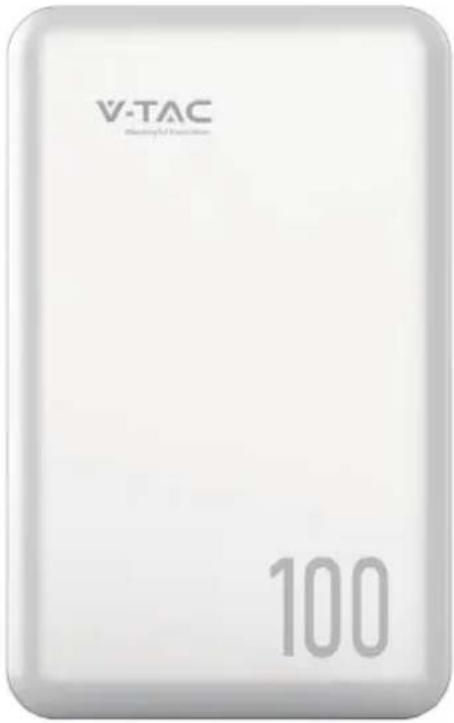
IP65
RATING
05 YEAR
WARRANTY*
INTRODUCTION
Thank you for selecting and buying V-TAC Product. V-TAC will serve you the best. Please read these instructions carefully & keep this user manual handy for future reference. If you have any another query, please contact our dealer or local vendor from whom you have purchased the product. They are trained and ready to serve you at the best.

MULTI-LANGUAGE MANUAL QR CODE
Please scan the QR code to access the manual in multiple languages.

FR
2.1 Safety Precautions.... 2
2.2 Abuse Operation.... 2
3 Overview.... 3
3.1 Product Description.... 3
3.1.1 Features.... 3
3.1.2 Basic Functions.... 3
3.2 Application Scenario....4
4 Application Description.... 5
4.1 Parallel Connection Application.... 5
4.2 Low-temperature Application....5
4.3 Low Battery-capacity Storage (SOC≤5%).... 5
4.4 Application of Nearing the Ocean....6
5 Product Introduction....7
5.1 Dimensions....7
5.2 Panel Introduction....7
5.3 PIN Definition....9
6 Installation....10
6.1 Precautions for Installation.... 10
6.2 Installation Preparation.... 10
6.2.1 Tools Preparation.... 10
6.3 Packing List.... 12
6.4 Unpacking and Inspection....12
6.5 Installation....13
6.6 Recommended Configuration....15
6.7 Cable Connection....16
6.7.1 Power Cable Connection....16
6.7.2 Communication Cable Connection....17
6.7.3 120Ω Resistor Connection....18
7 Parallel Connection....18
8 Make Your System Run....21
9 Shipment & Maintenance & Storage 23
9.1 Shipment.... 23
9.2 Maintenance.... 23
9.2.1 Battery Maintenance Considerations 23
9.2.2 Routine Maintenance.... 24
9.3 Battery Storage 25
10 Trouble Shooting.... 26
11 Warranty.... 27
12 Abbreviations.... 28
Overview
This user manual mainly introduces product introduction, application description, installation instructions, power-on instructions, maintenance instructions and provides instructions the VE51100W ESS Series LFP battery pack for technical support engineers, maintenance engineers and users.
Reader
This document is mainly applicable to the following engineers
• Technical Support Engineer
• Installation Personnel
- Maintenance Engineer
Signs
The following signs may appear in this article, and their meanings are as follows.
| Sign Meaning | Description | |
 | Danger | Indicates a hazard with a high level of risk that will cause death or serious injury if not avoided. |
 | Warning | Indicates a hazard with a moderate risk that may cause death or serious injury if not avoided. |
 | Notice | Indicates a hazard with a low level of risk that may cause minor or moderate harm if not avoided. |
 | Explanation | Supplementary explanation of key information in the main text."Explanation" is not safety warning information, and does not involve personal, equipment and environmental damage information. |
This marking indicates that this product should not be disposed of with other household wastes.
Caution, risk of electric shock.
2.1 Safety Precautions
Before carrying out battery work, you must read carefully the safety precautions and master the correct installation and connection methods of the battery.
• Prohibit to turn it upside down, tilt, or collide.
- Prohibit to short-circuit the positive and negative poles of the battery, otherwise it will cause the battery to be damaged.
• Prohibit to throw the battery pack into a fire source.
- Prohibit to modify the battery, and it is strictly prohibited to immerse the battery in water or other liquids.
• DO NOT place installation tools on the battery during battery installation.
- DO NOT disassemble, squeeze, bend, deform, puncture, or shred the battery without the authorization of authorized dealers.
- DO NOT exceed the temperature range, otherwise it will affect the battery performance and safety.
- The battery circuit must be kept disconnecting status during installation and maintenance operations.
- Check the battery connection end bolts regularly to confirm that the bolts are tight.
2.2 Abuse Operation
The battery pack needs to avoid abuse operations under the following (including but not limited to) conditions:
| Abuse Operation Protection Description | |
| Reverse connection of positive and negative poles | If the positive and negative poles are connected reversely, the battery will be directly damaged. |
| External short circuit | If the battery pack is short circuited externally, the battery will be directly damaged. |
| Series connection application | The battery pack does not support the application of battery packs in series. If the battery packs are forced to be connected in series, the batteries may be directly damaged, and may even cause fire, explosion and other dangers. |
3.1 Product Description
The VE51100W product use lithium iron phosphate (LFP) as the positive electrode material. It can be widely used in energy storage systems such as residential energy storage, back-up power, and PV self-consumption optimization.
The battery pack is composed of 16 cells of LFP batteries in series connection, with low self-discharge, high energy density, and no memory effect. This type of battery also has excellent performance in high rate, long cycle life, wide temperature range, and high safety.
3.1.1 Features
• High energy density
Higher volume ratio energy and weight ratio energy.
- Maintenance-free
The battery pack is maintenance-free in the process of using, which can save customers' battery operation, maintenance testing costs and reduce the frequency of on-site replacement.
- Long cycle life
The battery pack life is 3 times long than the ordinary lead-acid batteries.
• Excellent temperature characteristics
When charging, the battery working temperature can reach 0^ +60^ . (recommended using temperature: +15^ +35^ ). When discharging, the battery working temperature can reach -20^ +60^ . (recommended using temperature: +15^ +35^ ).
3.1.2 Basic Functions
- Monitor
The battery system uses a high-performance BMS, it has protection functions such as current, voltage.
- Alarm
Support abnormal alarms such as overvoltage, under-voltage, overcurrent, short circuit, high and low temperature, battery failure, hardware failure, etc.
- Communication
Provide 2*RJ45 interfaces, upload alarming and data of batteries through the RS485/CAN communication protocol.
- Parallel connection application
Max. support 15pcs batteries in parallel connection. (Recommendation: for better performance, when the number of batteries exceeds 2pcs, please connect all batteries to the bus-bar.)
• Balance function
Support the cell balance function.
3.2 Application Scenario
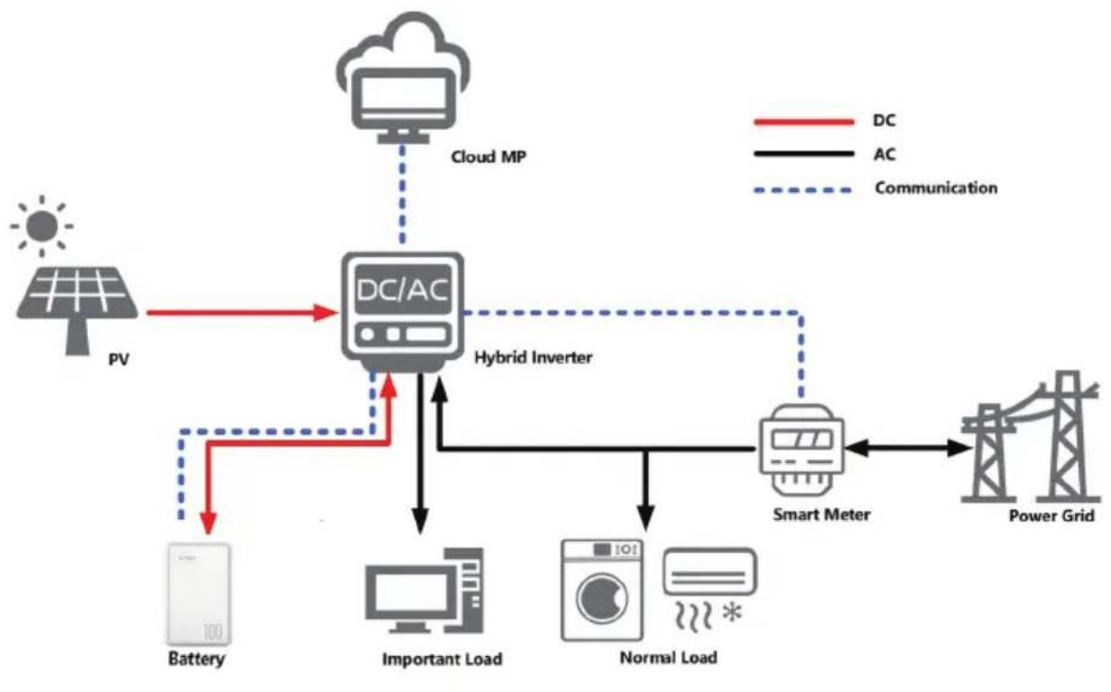
The battery pack is used to provide backup power, load shifting, peaking shaving and can be used for residential energy storage, solar energy storage and other application scenarios.
The normal working operation diagram of the battery pack can be as shown in the figure below.
flowchart
graph TD
    PV["Power Grid"] -->|DC| DC["DC/AC"]
    DC -->|AC| SmartMeter["Smart Meter"]
    SmartMeter --> PowerGrid["Power Grid"]
    DC -->|DC| CloudMP["Cloud MP"]
    CloudMP -->|Communication| DC
    DC -->|Battery| Battery["Battery"]
    DC -->|Important Load| Computer["Computer"]
    DC -->|Normal Load| WashingMachine[" Washing Machine"]
    DC -->|Hybrid Inverter| HybridInverter["Hybrid Inverter"]
    HybridInverter --> DC
Fig. 3-1 Working Diagram of the Battery Pack
4.1 Parallel Connection Application
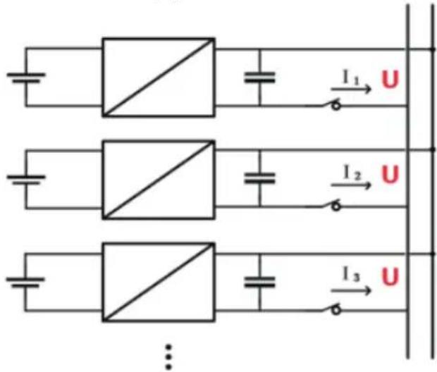
The battery packs support parallel connection, and synchronously increases the backup time or backup power.
Confirm the consistency between the battery packs, check the SOC and voltage and turn off the batteries before connecting them in parallel.
4.2 Low-temperature Application
• Low-temperature Charging
The battery pack does not support direct charging of the battery below 0^ C. When the minimum temperature of the battery is below 0^ C, the BMS will cut-off the charging circuit and cannot be charged.
- Low-temperature Discharging
The battery pack does not support discharge below -20^ . When the minimum temperature of battery is below -20^ , the BMS will cut-off the discharge circuit and cannot discharge.
4.3 Low Battery-capacity Storage (SOC≤5%)
After the battery pack is power off, there will be BMS static power consumption and self-discharge loss. In actual scenarios, it is necessary to avoid low-battery-power state (SOC≤5%) storage. If it is unavoidable, the longest storage period is 30
days@25°C, 15 days@45°C. The battery needs to be recharged in time after storage, otherwise the battery may be damaged due to over-discharge, and the entire battery pack needs to be replaced.
The following conditions may cause the battery pack to be stored in a discharged state:
- After the utility power failure, the line/fault cannot be eliminated in time, and the power supply cannot be restored for a long time.
- After the installation and commissioning work is completed, the utility power is turned off directly, but the battery pack is not powered off, which will cause the battery to enter the low power consumption mode.
- Other reasons cause the battery pack to fail to enter low power consumption normally.
4.4 Application of Nearing the Ocean
The atmospheric corrosion environment is defined and classified according to the natural environment state, and the A/B environment is defined as follows:
- A: environment refers to the ocean or the land near the pollution source, or the environment with simple shelter (such as awning). "Near the ocean" refers to the area 0.5 \~ 3.7km away from the ocean; "Near the pollution source" refers to the area within the following radius: 3.7km from the saltwater lake, 3km from heavy pollution sources such as smelters, coal mines, and thermal power plants, chemical industry, rubber, electroplating, etc. 2km from medium pollution sources such as chemical industry, rubber and electroplating, etc. And 1km from light pollution sources such as food, leather and heating boilers, etc.
- B: environment. Refers to the environment on land or outside with simple shelter (such as awning) within 500m from the coast, or the environment on the sea.
NOTE
- The VE51100W has an IP rating of IP65, which allows it to be used in A/B environment. However, for better performance, it is recommended to use an air-conditioning system if possible.
5 Product Introduction
5.1 Dimensions
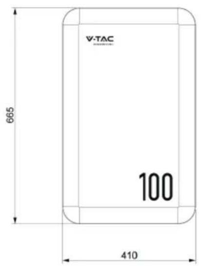
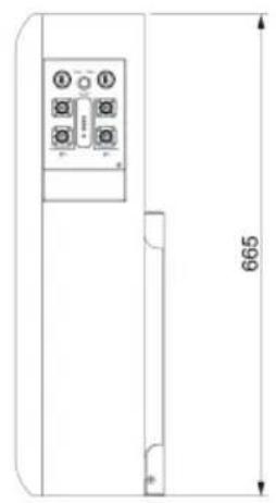
natural_image
Technical line drawing of a vertical panel with four buttons and a 665mm dimension label (no text or symbols beyond measurement lines)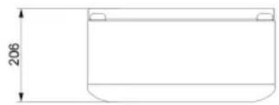
natural_image
Simple line drawing of a rectangular container with a side gap and height dimension labeled 206 (no text or symbols beyond the measurement)Fig. 5-1 Product Dimensions
5.2 Panel Introduction
The VE51100W operation panel is shown as follows.
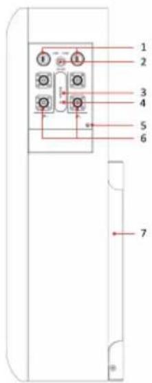
Fig. 5-2 VE51100W Operation Panel
The definition of the VE51100W operation panel is shown as follows.
Table 5-1 Operation Panel Interface Definition
| No. | Items Remark | |
| 1 | COM 1/COM 2 | 2*RJ45 Interface for communication:COM1 for communication with inverter;COM2 is used for communication between batteries. |
| 2 | POWER | Power switch |
| 3 | SOC | State of charge |
| 4 | RUN/ALM | To indicate the running or alarm status of battery |
| 5:GND | Grounding | |
| 6 | Battery Output Battery power terminals | |
| 7 | Bracket Battery bracket |
The SOC indicator used to identify the current capacity status of the battery. The number of blinking indicators corresponds to different remaining capacity. The specific meaning is shown as follows.
Table 5-2 The SOC Indicator Definition
| No. Indicator Light Remark | ||
| 1 0% | ≤ SOC ≤ 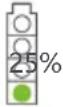 | |
| 2 | [H≤CS] | 25% < SOC ≤ 50% |
| 3 | [HTZH] | 50% < SOC ≤ 75% |
| 4 |  | 75% < SOC ≤ 100% |
The corresponding relationship between operation status and indicator operation status is shown as follows.
Table 5-3 The Run Indicator Definition
| Indication Status | ON OFF Battery Status | ||
| Flash 1 1 s 2 s | Idle | ||
| Flash 2 s Charge | 2 | 3 s | |
| Keep On | - | Discharge | |
| Keep Off | - | Sleep/Fault | |
Table 5-4 The Alarm Indicator Definition
| Indication Status ON OFF | Battery | Status | |
| Keep On | - | Fault (Charge/Discharge MOS、NTC、ADC Fault、Reverse Connection Fault) | |
| Keep Off | - | Standby/Sleep | |
5.3 PIN Definition
VE51100W has 2 communication interfaces: COM1 and COM2, the PIN definition of COM ports are shown as follows.
Table 5-5 The Communication Port Definition
| COM1/2 Pin Description | ||
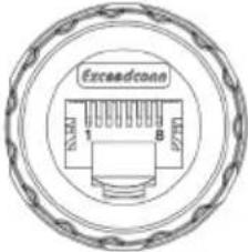 COM 1 COM 1 | 1 RS485_B | |
| 2 RS485_A | ||
| 3 CAN0-H (communicate with the last battery) | ||
| 4 | CAN1-H (communicate with inverter) | |
| 5 CAN1-L (communicate with inverter) | ||
| 6/8 / | ||
| CAN0-L (communicate with the last battery)7 | ||
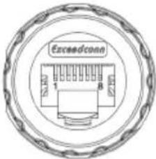 COM 2 COM 2 | 1 | RS485_B |
| 2 | RS485_A | |
| 3CAN0-H (communicate with the next battery) | ||
| 4/5/6/8 / | ||
| 7 CAN0-L (communicate with the next battery) | ||
6.1 Precautions for Installation
• Light intensity is required near the installation location.
- Comply with the safety operation technical regulations when lifting and handling heavy objects.
- Equipment and tools must be complete, intact, and reliable. It is strictly prohibited to use tools with cracks, burrs, loose handles, etc., that do not meet the safety standards.
• Installation operations must be guided by qualified engineers.
- During installation, two people must work together, one operating and the other inspecting.
- The original cable connection and operation process shall not change without the authorization of the company's consent.
6.2 Installation Preparation
6.2.1 Tools Preparation
ATTENTION
Use insulated tools to avoid electric shock. If you use tools without insulation protection, you need to wrap the exposed metal parts with insulation tape for insulation treatment.
The following table describes the tools and meters that may be used before installation.
Table 6-1 Installation
| Manual forklift | Electric forklift | Tape measure | Adjustable wrench |
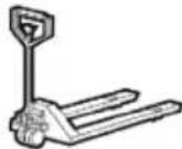 | 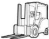 | 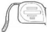 | 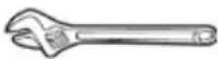 |
| Phillips screwdriver | Ladder | Levelling Instrument | Claw Hammer |
 | 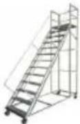 |  | 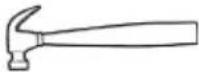 |
| Socket wrench Multimeter Insulated torque wrench Helmet | |||
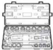 | 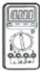 | 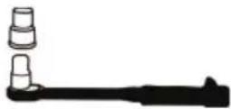 | 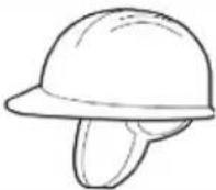 |
| Insulated shoes | Anti-static gloves | Goggles | Insulating tape |
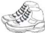 |  | 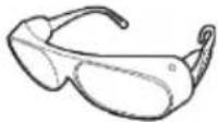 | 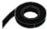 |
6.3 Packing List
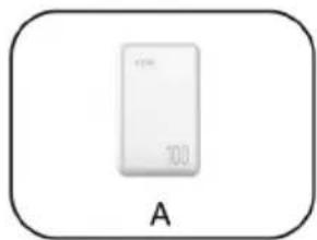
natural_image
White rectangular electronic device labeled 'A' with no visible text or symbols on its body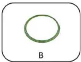
natural_image
Simple green circular ring labeled 'B' inside a rounded rectangle (no additional text or symbols)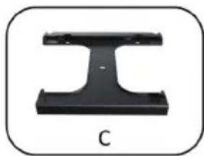
natural_image
Black metal I-beam component labeled 'C' (no other text or symbols)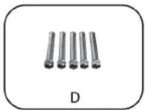
natural_image
Five metallic cylindrical pins arranged in a row, labeled 'D' below (no text or symbols on pins)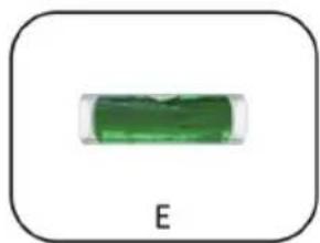
natural_image
Simple green rectangular object with label 'E' below, no other text or symbols visible
| Item Description Quantity | ||
| A | VE51100W battery | 1 |
| B | GND cable | 1 |
| C | Battery bracket | 1 |
| D | Expansion bolts | 5 |
| E | Spirit level | 1 |
| F | Mounting installation guide board | 1 |
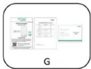
| G | User manual/Warranty card/Packing list | 1 |
6.4 Unpacking and Inspection
After receiving the goods on-site, please check whether the packing box is intact and inspect the goods in time. If the packing box is slightly damaged, please sign the cargo list to confirm receipt and indicate the extent of the damage. If the damage of the packing box is serious, please refuse to sign.
Please carry out an unpacking inspection after receiving all the goods. If users find that the received goods do not match the packing list, please contact Vtac as soon as possible.
6.5 Installation
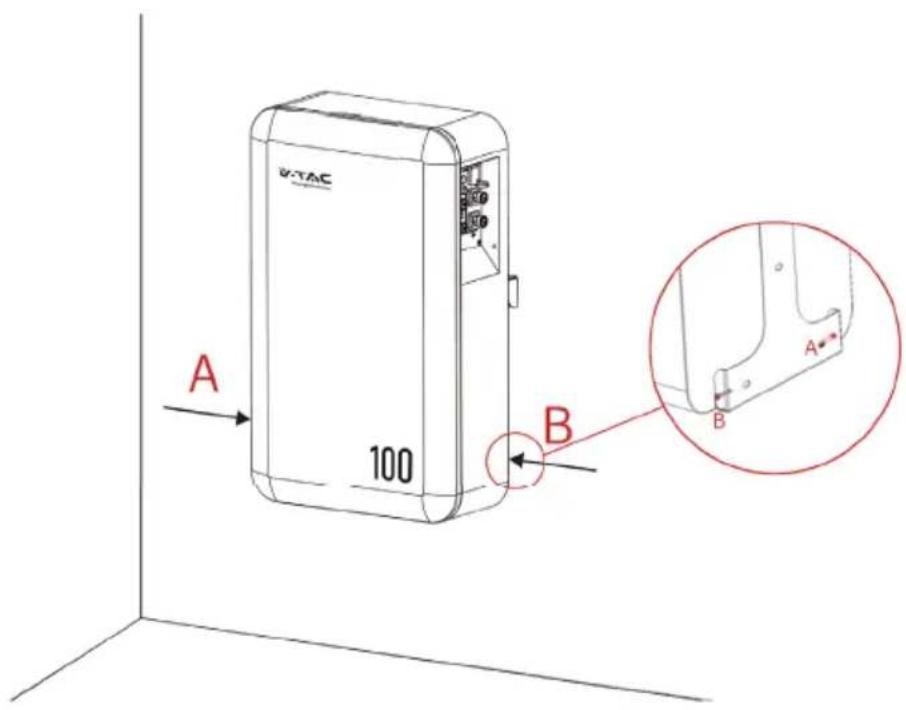
Step 1. Positioning the wall-mounting bracket on the wall, the requirements of installation space are as follows.
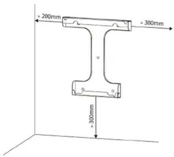
| Position Min. distance | |
| Left-side | 200 mm |
| Right-side | 300 mm |
| Bottom | 300 mm |
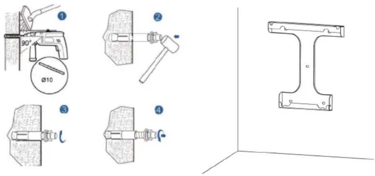
Step 2. Use a electric drill and spirit level to install the 'mounting backet' to the wall.
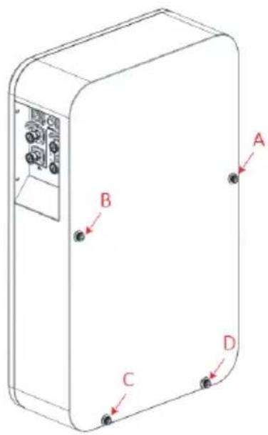
Step 3. Check whether the bolt torque of the nuts (4 nuts on the back of VE51100W) is 8 N.m.
Step 4. Install the VE51100W on the mounting bracket and fix it with original M5 screws on both sides.
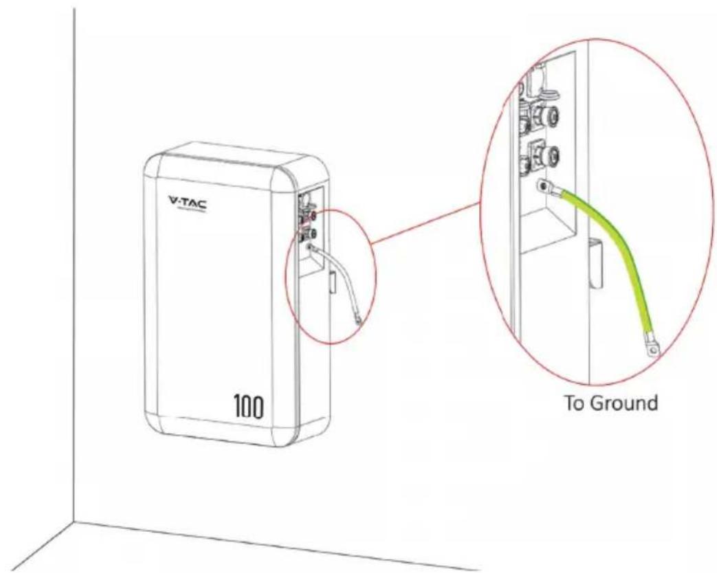
Step 5. Connect the grounding cable to the ground.
6.6 Recommended Configuration
According to the power rating of the inverter, requiring a corresponding minimum quantity of batteries in parallel:
a. When the inverter power ≤ 5kW: need to configure at least one VE51100W battery.
b. When 5kW < inverter power ≤ 10kW: need to configure at least two VE51100W batteries (connect in parallel).
6.7 Cable Connection
6.7.1 Power Cable Connection

NOTE
- Please contact Vtac or the supplier to purchase the following cables. They are maybe not included in the battery box and can be obtained in the Master/Slave Cable Kit provided by Vtac or the suppliers.
• How to use the touch-safe power cable connectors
Press the unlock on the power cable while inserting the power cable into the socket.
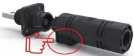
natural_image
Close-up of a black plastic electrical plug with a red hand icon pointing to its side (no text or symbols visible)Unlock
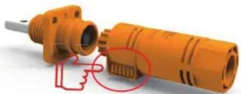
natural_image
Close-up of an orange industrial component with a red circular annotation highlighting a finger pointing to a detail (no text or symbols visible)Unlock
The following is the power cables connection display of the battery to the inverter.
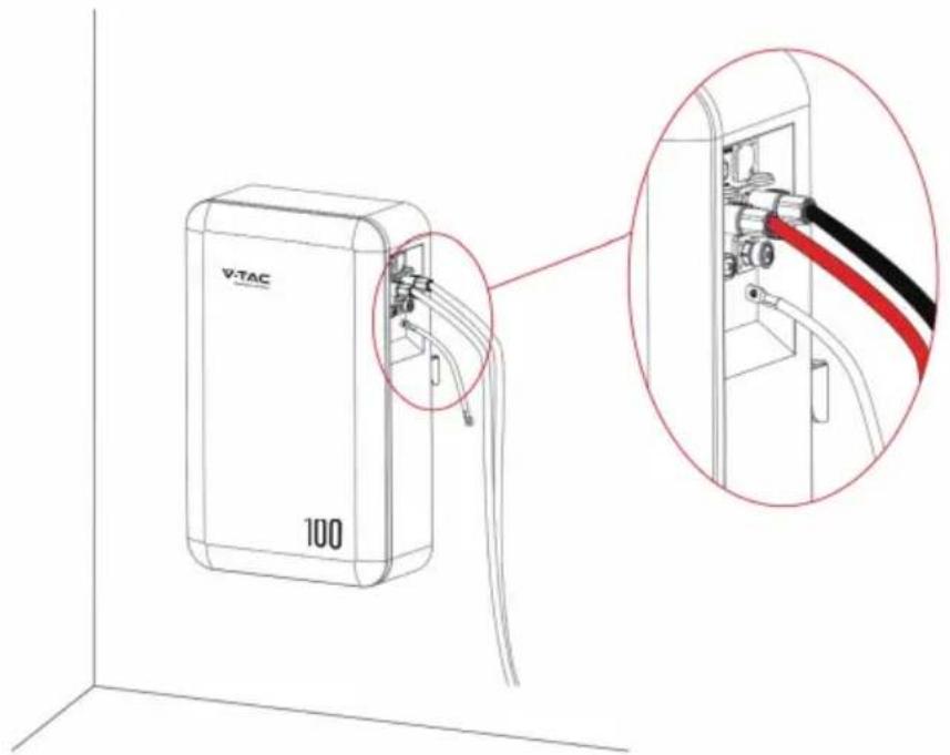
6.7.2 Communication Cable Connection
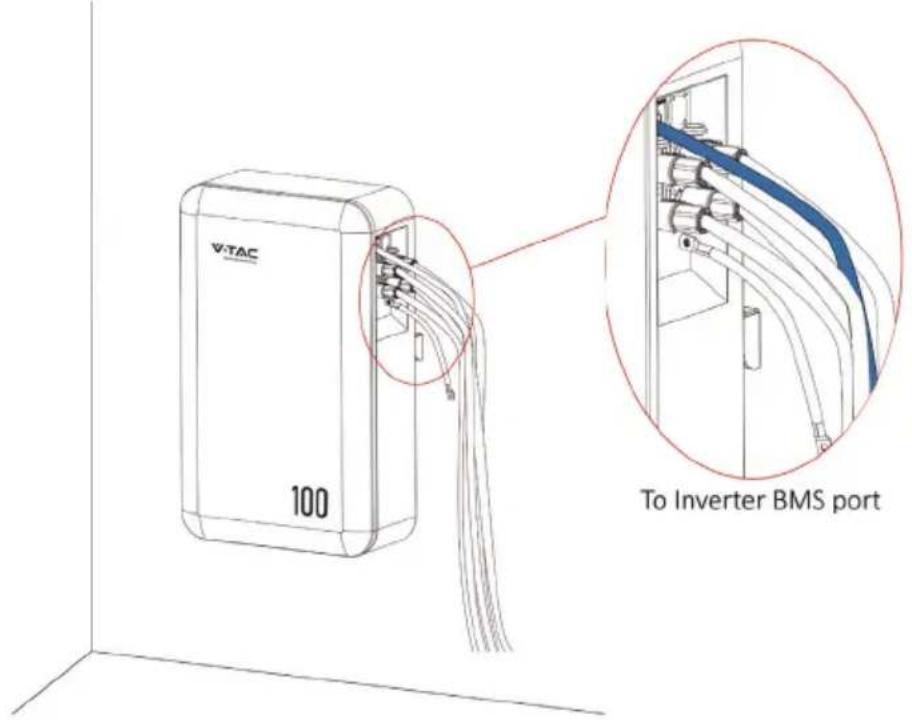
Locate the direction of the communication cable with the socket and then insert the communication cable to the socket.

NOTE
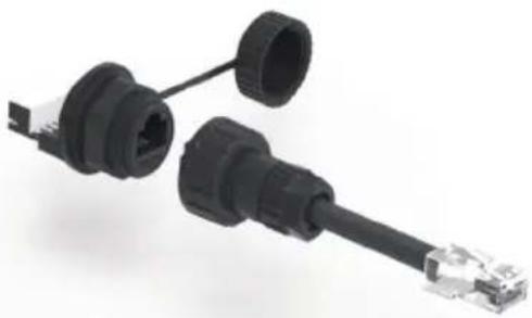
• How to use the communication cable connectors
Open the communication port cover, align it with the corresponding socket, and insert it.
natural_image
Close-up of a black USB connector with multiple ports and connectors (no text or symbols visible)The following is the communication cable connection display of the battery to the inverter.
6.7.3 120Ω Resistor Connection
To ensure stable communication with the inverter when using more than two batteries in parallel, follow these steps:
Step 1. Take out a 120Ω resistor from the 'Master Battery Cable Kit'.
Step 2. Insert the 120Ω resistor into the 'COM 2' port of the last VE51100W.
7 Parallel Connection
If you will install less than 2pcs batteries (Battery quantity≤2), please refer to the following wiring configuration.
| Battery Quantity of Parallel Cable Kit | |
| 1 pc Master Cable Kit * 1 set | |
| 2 pcs | Master Cable Kit * 1 set |
| Slave Cable Kit * 1 set | |
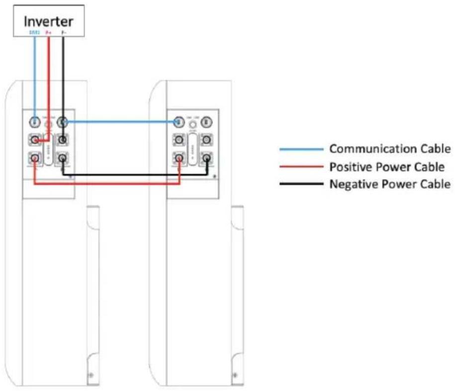
If you will install more than 2pcs batteries (No more than 15pcs), you will have the following two system wiring options.
Option 1. Connect all batteries to the bus bar.

NOTE
- For this wiring solution, you will need to prepare bus bars and power cables to connect the bus bars to the inverter in addition. You can either purchase them independently or obtain them from Vtac or the supplier.
- In this wiring solution, the Max. output current of the system will be 100A^* the quantity of batteries in parallel.
| Battery Quantity of Parallel Cable Kit | |
| 3 pcs | Master Cable Kit * 3 set |
| ⋮ | ⋮ |
| N pcs (4≤N<15) | Master Cable Kit * N set (4≤N<15) |
| ⋮ | ⋮ |
| 15 pcs | Master Cable Kit * 15 set |
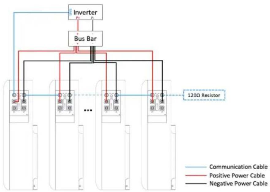
flowchart
graph TD
    A["Inverter"] --> B["Bus Bar"]
    B --> C["..."]
    B --> D["120Ω Resistor"]
    E["Communication Cable"] --> B
    F["Positive Power Cable"] --> B
    G["Negative Power Cable"] --> B
    style A fill:#f9f,stroke:#333
    style B fill:#ccf,stroke:#333
    style C fill:#cfc,stroke:#333
    style D fill:#fcc,stroke:#333
    style E fill:#ffc,stroke:#333
    style F fill:#fcc,stroke:#333
    style G fill:#ffc,stroke:#333
Option 2. Connect batteries by 'hand to hand'.

NOTE
- If you want to use this wiring method, please note that the Max. output current of the inverter is set in advance to 200A. To avoid damaging to the BMS.
| Battery Quantity of Parallel Cable Kit | |
| 3 pcs | Master Cable Kit * 2 set |
| Slave Cable Kit * 2 set | |
| 4 pcs | Master Cable Kit * 2 set |
| Slave Cable Kit * 3 set | |
| ⋮⋮ | ⋮ |
| N pcs (5≤N<15) | Master Cable Kit * 2 set |
| Slave Cable Kit * (N-1) set(5≤N<15) | |
| ⋮ | |
| 15 pcs | Master Cable Kit * 2 set |
| Slave Cable Kit * 14 set |
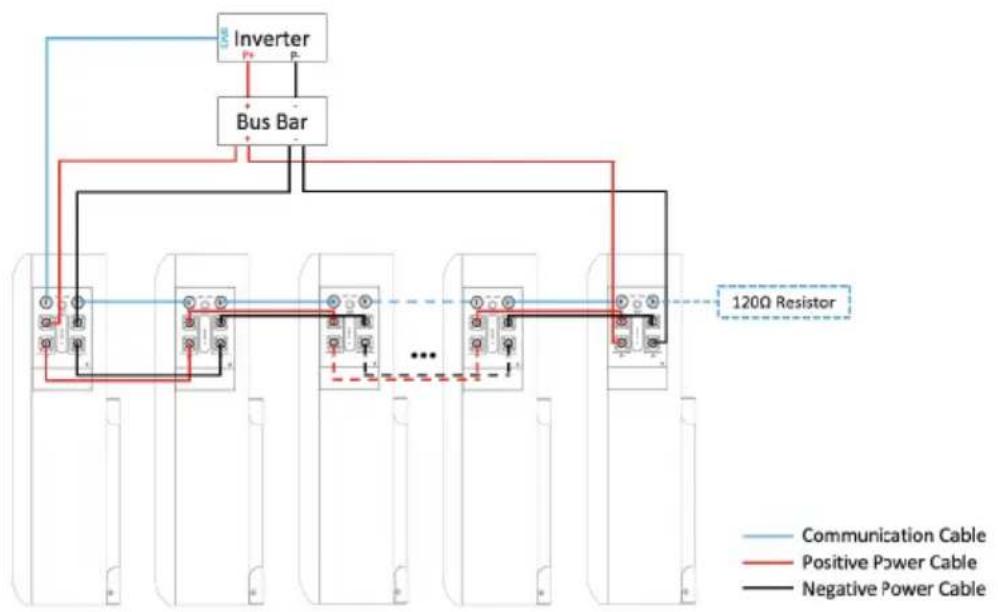
flowchart
graph TD
    A["Inverter"] --> B["Bus Bar"]
    B --> C["120Ω Resistor"]
    D["Communication Cable"] --> E["Bus Bar"]
    F["Positive Power Cable"] --> G["Bus Bar"]
    H["Negative Power Cable"] --> I["Bus Bar"]
    E --> J["..."]
    G --> K["..."]
    I --> L["..."]
    style A fill:#f9f,stroke:#333
    style B fill:#ccf,stroke:#333
    style C fill:#cfc,stroke:#333
    style D fill:#fcc,stroke:#333
    style E fill:#cff,stroke:#333
    style F fill:#ffc,stroke:#333
    style G fill:#fcc,stroke:#333
    style H fill:#ffc,stroke:#333
    style I fill:#fcc,stroke:#333
8 Make Your System Run

ATTENTION
- Please strictly follow the steps below for check and operation. Vtac will not be responsible for any issues caused by improper operation.
Parameter Setting
Table 8-1 Parameter Setting
| No. Description Value | Unit | ||
| 1 | Nominal Voltage | V | 51.2 |
| 2 | Float Charge Voltage | V | 57.6 |
| 3 | Recommended Charge Current | A | 20-30 |
| 4 100 | Max. Charge/Discharge Current | A | |
| 5 42 | Discharge Cut-off Voltage | V | |
| 6 0~60 | Charge Temperature Range | °C | |
| 7 -20~60 | Discharge Temperature Range | °C | |
| 8 15~35 | Storage Temperature Range | °C | |

NOTE
• The setting of different inverters will be different.
• Make sure the inverter/charger is powered on before powering on the battery.
- Must not change the parameters casually in the site.
Check before Running
Step 1. Check whether the cables are connected correctly.
Step 2. Check whether the batteries are grounded.
Step 3. Check these following status of switches.
The power switch of the battery should be off.
The DC switch of the inverter should be off.
The circuit breaker from the inverter to the grid should be off.
Power-on
Step 4. Turn on the DC switch of inverter.
Turn on the switch between the inverter and grid.
Turn on the circuit breaker between the inverter and battery (if any).
Step 5. Turn on the power switch of battery. And waiting for the Run/Alarm indicator lights from green blinking into green, means power on successfully!
NOTE
• If you want to Power off your system
If you need to shut down the system for some reason, please refer to the following steps.
Step 1. Turn off the inverter first.
Step 2. Turn off the battery then.
9.1 Shipment
It is suitable for the transportation of vehicles, ships and airplanes. During transportation, shading, sun protection and civilized loading and unloading should be performed. The box containing the product is allowed to be transported by any means of transportation. In the process of loading and unloading, the battery should be handled with care to prevent falling, rolling, and heavy pressure. Avoid direct rain and snow and mechanical impact during transportation.
And here is the suggestion for the initial SOC before shipment by different transportation:
- Airplane:30%\~40%
- Sea:50%\~60%
• Vehicle:50%\~60%
NOTE
- Whether the loading SOC status of the battery is allowed, you need to consult the relevant government transportation department.
9.2 Maintenance
9.2.1 Battery Maintenance Considerations
When maintaining the battery, it is required to use insulated tools or wrap the tools in insulation.
- DO NOT place any debris on the top of the battery.
- DO NOT use any organic solvents to clean the battery.
- DO NOT smoke or use naked flames near the battery.
• After the battery is discharged, the battery should be charged in time to avoid affecting the battery life.
- When not using the battery for a long time, please charge the battery to 40%\~50% charged state. Long-term storage with low battery may damage the battery.
- All maintenance work must be carried out by professionals.
9.2.2 Routine Maintenance
The staff should perform visual inspection on VE51100W battery according to the inspection plan, please refer to the following table for maintenance.
Table 9-1 Routine Maintenance (Every three-month)
| Items Standard Dealing | ||
| Battery Appearance | The surface is neat and clean without stains.The terminals are in good condition.The battery pack shell is intact, and there is no bumps, breaks, or leakage.The appearance of the battery pack does not leak.No deformation or swelling of the shell. | If the surface is dirty, clean the appearance of the battery pack with a cotton cloth.The battery pack terminal is damaged, replace the cable.If the appearance is damaged, leaking or deformed, take a photo and replace the defective battery pack.Please contact supplier or the authorized dealers in time for other abnormal situations. |
| Alarm | No Alarm. | Find the solution as per alarm information |

NOTE
• Suggested routine maintenance for every three-month.
Table 9-2 Routine Maintenance (Every six-month)
| Items Standard Action | ||
| (Suggested) Complete Cycle | Have a complete charge & discharge cycleunder the equipment no lack of power. | Check whether happens alarm action, and please check with the alarm list.Please contact with supplier or the authorized dealers if the alarm still exists. |
| Cables | There is no aging of the connecting wire and no cracking of the insulation layer.The bolts at the cable connection are not loose. | Replace the faulty connection.Fastening bolts. |
9.3 Battery Storage
• The recommended storage temperature is 15^ C\~ 35^ C.
- Battery performance degradation after long-term storage, please shorten shelf time as possible as you can.
- Recharge charge before using to recover capacity loss of self-discharge during storage and transport.
- Storage battery should be at 40%-50% SOC when the battery is not used for a long time.
• Storage battery over 40°C or under 0°C will reduce battery life.
• Storage battery in dry and low temperature, well ventilated place.
If the battery is not used for a long time, the battery must be charged at regular intervals. The charging requirements are as follows:
Table 9-3 Battery Charge Requirement in Storage Status
| Storage Temp. | Charge Period | Charge Process |
| 20°C~30°C | Each 6 months | 1.Charge by 0.2C to 100% SOC2.Discharge by 0.2C to 0% SOC3.Charge by 0.2C to 40%~50% SOC |
| 0°C~20°C or 30°C~40°C | Each 3 months |
Please refer to the table below to deal with common faults:
Table 10-1 FAQ
| Phenomenon | Possible cause Solution | |
| The indicator does not flash | The power cable of the battery pack is not properly connected.The power switch is off.The BMS is in a sleep state.BMS is damaged. | Reconnect the power cable of the battery pack.Turn on the power switch.Charge the battery pack.Replace BMS. |
| Unable to discharge | The terminal of the battery pack is damaged.BMS communication failure.The power switch is off. | Replace the battery pack wiring terminals.Reconnect the communication line between the BMS and the battery pack. If the communication cable is damaged, replace the communication cable.Turn on the power switch. |
| Unable to charge | The charger is malfunctioning.The terminal of the battery pack is damaged.BMS communication failure.The power switch is off. | Replace the charger.Replace the battery pack wiring terminals.Reconnect the communication line between the BMS and the battery pack. If the communication cable is damaged, replace the communication cable.Turn on the power switch. |
| Communication fail | The power switch is off.The BMS is in a sleep status.The communication cable is damage. | Turn on the power switch.Charge the battery pack.Replace the network cable. |
| Inaccurate voltage display | The voltage sampling line is damaged.BMS is damaged. | Replace the voltage sampling line.Replace BMS. |
| Low capacity | The battery pack has not been maintained for a long time.The single battery is damaged.Inaccurate voltage sampling. | Use an equalizer to maintain the battery pack.Replace the damaged single battery.Replace the electrical sampling line or replace the BMS. |
| Low cell voltage | The battery pack has not been maintained for a long time.The single battery is damaged.Inaccurate voltage sampling. | Use an equalizer to maintain the battery pack.Replace the damaged single battery.Replace the electrical sampling line or replace the BMS. |
Except for the following and the conditions specified in the contract, you can go to the supplier or the authorized dealers for reasonable warranty and maintenance.
- Failure of equipment caused by unauthorized disassembly and maintenance operations without the supplier or the authorized dealers is not within the scope of the warranty.
- Equipment damage caused by negligence during storage and transportation is not covered by the warranty.
- The damage to the equipment caused by continuous overload work outside the electrical parameters of the equipment is not covered by the warranty.
- Unauthorized testing of the equipment without the supplier and the authorized dealers will not be covered by the warranty.
- Non-equipment problems, adverse consequences caused by operation and matching problems are not covered by the warranty.
- Equipment damage caused by natural forces, force majeure, and uncontrol-lable factors, such as earthquakes, typhoons, tornadoes, volcanic eruptions, floods, lightning, heavy snow, and wars, is not covered by the warranty.
- If the product serial number is changed, blurred, or torn, it is not covered by the warranty.
IMPORTANT NOTES
- This product contains battery type "Secondary" (rechargeable).
- Electrical and electronic equipment that has become waste is known as old equipment/device. Old devices must not be disposed of with other household waste.
- Owners of old devices at the end of its service life must return the device by taking them to the collection points set up by public waste disposal authorities or distributors. This return does not entail any costs for you.
- Owners of old devices have an obligation to remove accessible batteries / rechargeable batteries as well as non-destructively removable lamps from the old device prior to return. This does not apply if old devices are being prepared for reuse with the participation of a public law firm.
- Battery removal warning: The battery contained in this product must be removed only by professional personnel only. The battery must never be removed by the end user, if not removed correctly it could damage the battery which could cause fire.
- Batteries removed from an old electronic device should be disposed of separately. This return of battery does not entail any costs for you and the user is obliged to return the battery.
- Please make sure that this product is not powered on when removing the battery. Fire hazard! Avoid short-circuiting the contacts of a detached battery. Do not incinerate the battery. Please handle the battery with Caution!
- If electrical appliances or batteries are disposed of in landfills or dumps, hazardous substances can leak into the groundwater and get into the food chain, damaging your health and well-being.

- The symbol of "Crossed rubbish bins" indicates that this product should not be disposed of with other household wastes and must be collected separately from unsorted municipal waste at the end of its service life.
- Please use the link below to view the online directory of the collection and return points:https://www.ear-system.de/ear-verzeichnis/sammel-und-ruecknahmestellen
BMS Battery Management System
D Depth
H Height
LCD Liquid Crystal Display
LFP LiFePO4
MOSFET Metal-Oxide-Semiconductor Field-Effect
Transistor
NTC Negative Temperature Coefficient
PC Personal Computer
PCB Printed Circuit Board
PCS Power Conversion System
RTU Remote Terminal Unit
SOC State of Charge
W Width
RoHS






V-TAC
Meaningful Innovation.
VTAC EUROPE LTD
Bulgaria, Plovdiv 4000, bul.L.Karavelow 9B
- INSTRUCTION MANUAL
- 5.12kWh WALL MOUNTED
- LITHIUM BATTERY
- INTRODUCTION
- MULTI-LANGUAGE MANUAL QR CODE
- Overview
- Reader
- Signs
- Safety Precautions
- Abuse Operation
- Product Description
- Features
- • High energy density
- - Maintenance-free
- - Long cycle life
- • Excellent temperature characteristics
- Basic Functions
- - Monitor
- - Alarm
- - Communication
- - Parallel connection application
- • Balance function
- Application Scenario
- Parallel Connection Application
- Low-temperature Application
- • Low-temperature Charging
- - Low-temperature Discharging
- Low Battery-capacity Storage (SOC≤5%)
- Application of Nearing the Ocean
- NOTE
- Panel Introduction
- PIN Definition
- Precautions for Installation
- Installation Preparation
- Tools Preparation
- ATTENTION
- Packing List
- Unpacking and Inspection
- Installation
- Recommended Configuration
- Cable Connection
- Power Cable Connection
- Communication Cable Connection
- • How to use the communication cable connectors
- 120Ω Resistor Connection
- Parallel Connection
- Option 2. Connect batteries by 'hand to hand'.
- Make Your System Run
- Parameter Setting
- Check before Running
- Power-on
- • If you want to Power off your system
- Shipment
- Maintenance
- Battery Maintenance Considerations
- Routine Maintenance
- Battery Storage
- IMPORTANT NOTES
- V-TAC
Brand : V-TAC
Model : VE51100W
Category : Battery charger