
VT-48100E - Battery charger V-TAC - Free user manual and instructions
Find the device manual for free VT-48100E V-TAC in PDF.


| Product Type | Battery Charger |
| Brand | V-TAC |
| Model | VT-48100E |
| Input Voltage | 230V AC, 50Hz |
| Output Voltage | 48V DC |
| Output Current | 100A |
| Charging Mode | Automatic multi-stage (bulk, absorption, float) |
| Compatible Battery Types | Lead-acid (AGM, GEL, flooded) |
| Dimensions (L x W x H) | 300 x 200 x 150 mm |
| Weight | 5 kg |
| Protection Features | Overcharge, reverse polarity, short circuit, overheat |
| Cooling | Fan-cooled |
| Display | LED indicators for charging status and faults |
| Efficiency | >85% |
| Operating Temperature | -10°C to 40°C |
| Certification | CE, RoHS |
| Maintenance | Keep clean, ensure ventilation, check connections regularly |
| Safety Instructions | Use in dry area, disconnect AC before connecting battery, avoid water ingress |
Frequently Asked Questions - VT-48100E V-TAC
User questions about VT-48100E V-TAC
0 question about this device. Answer the ones you know or ask your own.
Ask a new question about this device
Download the instructions for your Battery charger in PDF format for free! Find your manual VT-48100E - V-TAC and take your electronic device back in hand. On this page are published all the documents necessary for the use of your device. VT-48100E by V-TAC.
USER MANUAL VT-48100E V-TAC
WEEE Number: 80133970
INSTRUCTION MANUAL
ESS SERIES BATTERY PACK
INTRODUCTION

Thank you for selecting and buying V-TAC Product. V-TAC will serve you the best. Please read these instructions carefully & keep this user manual handy for future reference. If you have any another query, please contact our dealer or local vendor from whom you have purchased the product. They are trained and ready to serve you at the best.

Multi-Language Manual QR CODE
Please scan the QR code to access the manual in multiple languages.
1 Foreword
Overview
This user manual mainly introduces product introduction, application description, installation instructions, power-on instructions, maintenance instructions and provides instructions the VT48100E-W ESS Series LFP battery pack for technical support engineers, maintenance engineers and users.
Reader
This document is mainly applicable to the following engineers
• Technical Support Engineer
• Installation Personnel
- Maintenance Engineer
Signs
The following signs may appear in this article, and their meanings are as follows.
| Sign | Meaning | Description |
 | Danger | Indicates a hazard with a high level of risk that will cause death or serious injury if not avoided. |
 | Warning | Indicates a hazard with a moderate risk that may cause death or serious injury if not avoided. |
 | Notice | Indicates a hazard with a low level of risk that may cause minor or moderate harm if not avoided. |
 | Explanation | Supplementary explanation of key information in the main text."Explanation" is not safety warning information, and does not involve personal, equipment and environmental damage information. |
2.1 Safety Precautions
Before carrying out battery work, you must read carefully the safety precautions and master the correct installation and connection methods of the battery.
• Prohibit to turn it upside down, tilt, or collide.
- Prohibit to short-circuit the positive and negative poles of the battery, otherwise it will cause the battery to be damaged.
• Prohibit to throw the battery pack into a fire source.
- Prohibit to modify the battery, and it is strictly prohibited to immerse the battery in water or other liquids.
- DO NOT place installation tools on the battery during battery installation.
- DO NOT disassemble, squeeze, bend, deform, puncture, or shred the battery without the authorization of authorized dealers.
- DO NOT exceed the temperature range, otherwise it will affect the battery performance and safety.
- The battery circuit must be kept disconnecting status during installation and maintenance operations.
- Check the battery connection end bolts regularly to confirm that the bolts are tight.
2.2 Abuse Operation
The battery pack needs to avoid abuse operations under the following (including but not limited to) conditions:
| Abuse Operation | Protection Description |
| Reverse connection of positive and negative poles | If the positive and negative poles are connected reversely, the battery will be directly damaged. |
| External short circuit | If the battery pack is short circuited externally, the battery will be directly damaged. |
| Series connection application | The battery pack does not support the application of battery packs in series. If the battery packs are forced to be connected in series, the batteries may be directly damaged, and may even cause fire, explosion and other dangers. |
3.1 Product Description
The VT48100E-W ESS Series product use lithium iron phosphate (LFP) as the positive electrode material. It can be widely used in energy storage systems such as residen-tial energy storage, back-up power, and PV self-consumption optimization.
The battery pack is composed of 16 cells of LFP batteries in series connection, with low self-discharge, high energy density, and no memory effect. This type of battery also has excellent performance in high rate, long cycle life, wide temperature range, and high safety.
3.1.1 Features
• High energy density
Higher volume ratio energy and weight ratio energy.
- Maintenance-free
The battery pack is maintenance-free in the process of using, which can save customers' battery operation, maintenance testing costs and reduce the frequency of on-site replacement.
- Long cycle life
The battery pack life is 3 times long than the ordinary lead-acid batteries.
• Excellent temperature characteristics
When charging, the battery working temperature can reach 0^ +60^ (recommended using temperature: +15 +35^ ). When discharging, the battery working temperature can reach -20^ +60^ (recommended using temperature: +15 +35^ ).
3.1.2 Basic Functions
- Monitor
The battery system uses a high-performance BMS, it has protection functions such as current, voltage.
- Alarm
Support abnormal alarms such as overvoltage, under-voltage, overcurrent, short circuit, high and low temperature, battery failure, hardware failure, etc.
- Communication
Provide 2*RS485 interfaces, upload alarming and data of batteries through the RS485/CAN communication protocol.
3 Overview
• Parallel connection application
Support multiple battery packs in parallel, RS485/CAN communication supports up to 6 groups without control unit (or max supports 15 groups with control unit).
• Balance function
Support the cells balance function.
3.2 Application Scenario
The battery pack is used to provide backup power, load shifting, peaking shaving and can be used for residential energy storage, solar energy storage and other application scenarios.
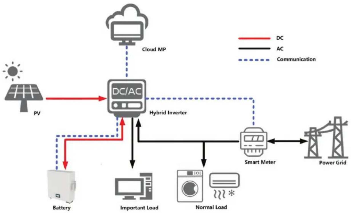
The normal working operation diagram of the battery pack can be as shown in the figure below.
flowchart
graph TD
    A["PV"] --> B["DC/AC"]
    B --> C["Cloud MP"]
    C --> D["Hybrid Inverter"]
    D --> E["Smart Meter"]
    E --> F["Power Grid"]
    G["Battery"] --> B
    H["Important Load"] --> D
    I["Normal Load"] --> E
    J["Communication"] -.-> B
    K["DC"] -.-> B
    L["AC"] -.-> B
Figure 3-1 Working Diagram of the Battery Pack
4.1 Parallel Connection Application
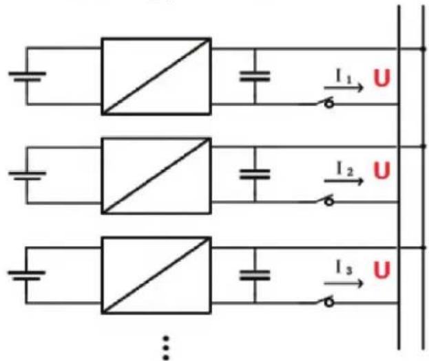
The battery packs support parallel connection, and synchronously increases the backup time or backup power.
Confirm the consistency between the battery packs, check the SOC and voltage and turn off the batteries before connecting them in parallel.
Multiple battery packs of parallel connection need to use to communicate, pay attention to the DIP switch settings.
4.2 Low-temperature Application
• Low-temperature Charging
The battery pack does not support direct charging of the battery below 0^ C. When the minimum temperature of the battery is below 0^ C, the BMS will cut-off the charging circuit and cannot be charged.
• Low-temperature Discharging
The battery pack does not support discharge below -20^ . When the minimum temperature of battery is below -20^ , the BMS will cut-off the discharge circuit and cannot discharge.
4.3 Low Battery-capacity Storage (SOC≤5%)
After the battery pack is power off, there will be BMS static power consumption and self-discharge loss. In actual scenarios, it is necessary to avoid low-battery-power state (SOC≤5%) storage. If it is unavoidable, the longest storage period is 30
4 Application Description
days@25°C, 15 days@45°C. The battery needs to be recharged in time after storage, otherwise the battery may be damaged due to over-discharge, and the entire battery pack needs to be replaced.
The following conditions may cause the battery pack to be stored in a discharged state:
- After the utility power failure, the line/fault cannot be eliminated in time, and the power supply cannot be restored for a long time.
- After the installation and commissioning work is completed, the utility power is turned off directly, but the battery pack is not powered off, which will cause the battery to enter the low power consumption mode.
- Other reasons cause the battery pack to fail to enter low power consumption normally.
4.4 Application of Nearing the Ocean
The atmospheric corrosion environment is defined and classified according to the natural environment state, and the A/B environment is defined as follows:
- A: environment refers to the ocean or the land near the pollution source, or the environment with simple shelter (such as awning). "Near the ocean" refers to the area 0.5 \~ 3.7km away from the ocean; "Near the pollution source" refers to the area within the following radius: 3.7km from the saltwater lake, 3km from heavy pollution sources such as smelters, coal mines, and thermal power plants, chemical industry, rubber, electroplating, etc. 2km from medium pollution sources such as chemical industry, rubber and electroplating, etc. And 1km from light pollution sources such as food, leather and heating boilers, etc.
- B: environment. Refers to the environment on land or outside with simple shelter (such as awning) within 500m from the coast, or the environment on the sea.
NOTE
The battery pack can be used under other environmental conditions and cannot be used alone under A/B environment. If it is to be used in the A/B environment, it needs to be equipped with a high-protection air-conditioning cabinet, which is recommended to be IP55 or higher.
5.1 Panel Introduction
5.1.1 Panel Function

Figure 5-1 Front Panel
The interface definition as below table:
Table 5-1 Operation Panel Interface Definition
| No. | Name | Description | Remark |
| 1 | Hangers | To fix the battery | |
| 2 | Power | Power switch | |
| 3 | SOC | State of charge | Details shows in table 5-3 |
| 4 | ALM | Alarm light | Details shows in table 5-4 |
| 5 | RUN | Run light | Details shows in table 5-4 |
| 6 | RESET | Reset switch | |
| 7 | BAT ID | Dip Switch | Address range 0~15 |
| 8 | RJ-11 | RJ-11 interface for firmware update | Used only for professional maintenance |
| 9 | RJ-45 | 2*RJ-45 interface for RS485/CAN communication | |
| 10 | Battery Output | Power terminal '+' '-' | |
| 11 | GND | Module ground connection | |
| 12 | LED | To display battery information |
5 Product Introduction
5.1.2 Indicator Description
Rack Mounting: When battery is fixed on the rack. There are 6 Indicators on the operation panel, divided into three types: 4 green SOC Indicators, 1 red alarm Indicator and 1 green run indicator.
Table 5-2 Indicators Flash Mode
| Flash Mode | ON | OFF | Common Name |
| Flash 1 | 0.25 s | 3.75 s | / |
| Flash 2 | 0.5 s | 0.5 s | Slow Flash |
| Flash 3 | 0.5 s | 1.5 s | / |
| Flash 4 | 0.25 s | 0.25 s | Strobe |
The power indicator is used to identify the current capacity status of the battery. The number of flashing indicators corresponds to different remaining capacity. The specific meaning is shown in the following table.
Table 5-3 SOC Indicator Definition
| QTY | Remaining Capacity Range | ||||
| 1 | • | 0% < SOC≤25% | |||
| 2 | • | • | 25% < SOC≤50% | ||
| 3 | • | • | • | 50% < SOC≤75% | |
| 4 | • | • | • | • | 75% < SOC≤100% |
5 Product Introduction
The corresponding relationship between battery operation status and indicator operation status is shown in the following table.
Table 5-4 Battery Status and Indicator Operation Mode
| Battery status | Normal/Abnormal | RUN | ALM | SOC Indicators | Description | |||
| - | - | ● | ● | ● | ● | ● | ● | - |
| Power off/Sleep | - | OFF | OFF | OFF | OFF | OFF | OFF | - |
| Standby | Normal | Flash 1 | OFF | According to SOC | Flash mode shown in Table 5-3 | |||
| Charge | Normal | Flash 2 | OFF | According to SOC | ||||
| Discharge | Normal | ON | OFF | According to SOC | - | |||
| Alarm | Abnormal | According to the state of charge and discharge | Flash 2 | According to SOC | Recoverable | |||
| Error | Abnormal | OFF | ON | OFF | - | |||
5 Product Introduction
5.1.3 DIP Address
To communicate with the battery, you need to assign an address to the battery BMS through the DIP switch.
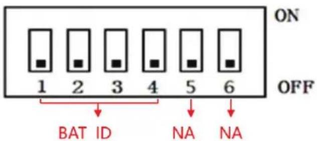
The relationship between DIP address and BMS address as below:
Table 5-5 Correspondence between BMS and DIP Switch
- CAN communication setting: set the master battery's DIP address to '0'. and for the remaining battery's DIP addresses need to increase sequentially. RS 485 communication setting: set the batteries' DIP addresses from 1-15.
5.1.4 Communication Port Definition
RJ-45 definition as below:
Table 5-6 RJ-45 Definition
| RJ 45Photo | Pin | Description |
 | 1/2/3 | NC |
| 4 | RS485_A | |
| 5 | CAN_L | |
| 6 | CAN_H | |
| 7 | RS485_B | |
| 8 | GND |

NOTE
- Please confirm the PIN of the communication cable before use. If you use a communication cable that does not meet the requirements, this may cause communication failure.
6 Installation
6.1 Tools Preparation

ATTENTION
Use insulated tools to avoid electric shock. If you use tools without insulation protection, you need to wrap the exposed metal parts with insulation tape for insulation treatment.
The following table describes the tools and meters that may be used before installation.
Table 6-1 Installation
| Manual forklift | Electric forklift | Tape measure | Adjustable wrench |
 |  |  |  |
| Phillips screwdriver | Ladder | Levelling Instrument | Claw Hammer |
 |  |  |  |
| Socket wrench | Multimeter | Insulated torque wrench | Helmet |
 |  |  |  |
| Insulated shoes | Anti-static gloves | Goggles | Insulating tape |
 |  |  |  |
6.2 Unpacking and Inspection
• Study this manual carefully before any installation of the batteries.
- The batteries must only be installed and operated by trained personnel.
- Check the quantity of battery and accessories with delivery list.
- Check the appearance whether there is damaged or leakage, if any damage is detected, please do not proceed to the next installation.
6.3 Preparing for Installation
- Make sure to disconnect and isolate the battery from any electrical source, and then turn on the power switch. Verify that the red ALM LED does not stay on for more than 30 seconds.
- Turn off the switch and continue with the installation.
6.4 Installation
The way to place when battery is idle is as follows (included the right and wrong way).

natural_image
Three technical line drawings of electronic device modules, showing front, side, and top views with no text or symbols.Figure 6-1 Place the Battery
6 Installation
6.4.1 Wall Mounting
Make sure that there is enough installation space before installation, and please install it on the wall according to the following figure.
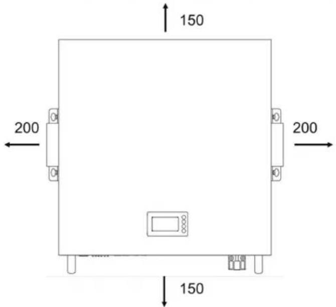
Table 6-2 Installation Space Requirement
| Min. Distance | |
| Left | 200mm |
| Right | 200mm |
| Top | 150mm |
| Bottom | 150mm |
6-2 Installation Space Requirement
Wall mounting is as follows (included the right and wrong way).
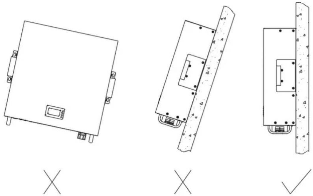
natural_image
Three technical line drawings of electronic components with mounting holes and mounting brackets, labeled X and ✓ (no text or symbols on the diagrams themselves)Figure 6-3 Wall Mounting
6 Installation
2 Make sure the battery is in off status.
3 Install the expansion bolt.
A. Please make sure that the thickness of the wall for battery module installation is more than 60mm;
B. Please place the bitmap horizontally on the wall and confirm the level by level;
C. Please mark the holes in the 4 mounting holes of hole pattern;
D. Drill a hole with a depth of 35-40mm at the mark with a drill of 8mm ;
E. Please expand the bolt with a hammer into the hole in the wall and install the nut (including elastic flat pad), do not tinghten the nut;
F. Please hang the battery module on the expansion bolt and tighten the nut with a wrench.
The schematic diagram of installing expansion bolts is as follows:

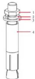
1 M6 bolt
2 Spring washer
3 Flat washer
4 Expansion tube
Figure 6-4 Install Expansion Bolt (unit: mm)
6 Installation

NOTE
- The depth of the expansion bolts knocked into the wall shall be subject to the entry of all expansion pipes into the holes.
• The battery needs to be installed indoors, avoiding direct sunlight, rain, snow. - Installation wall requirements: please install the battery on a solid concrete wall, do not install the battery on a light or loose wall.

ATTENTION
- The battery pack should be installed by professionally trained personnel, and it is strictly forbidden to install it without permission.
- Use insulated tools to avoid electric shock. If you use tools without insulation protection, you need to wrap the exposed metal parts with insulation tape for insulation treatment.
- The battery pack is heavy, and at least 4 manpower must be prepared during the transportation and installation process.
- If possible, please use tools to assist in handling.
6 Installation
6.5 Cable Connection
6.5.1 Power Cable Connection
Use the negative power cable to connect the negative bus bar with the battery negative (‘-’) terminal, and use the positive power cable to connect the positive bus bar with the battery positive (‘+’) terminal.
A. The last power cable connected to the charger or inverter needs to be configured according to the actual current that may exceed 100A.
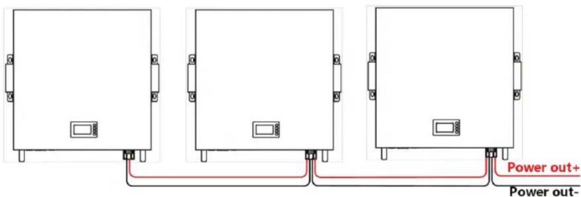
Figure 6-5 Connect the Battery Pack Power Cable
B. If the battery total input/output current more than 100A in parallel, the wiring method should configure bus-bars to connect the power cables.

Figure 6-6 Connect the Battery Pack Power Cable to Bus-bars
ATTENTION
- DO NOT use the batteries and cables with more than 100A current, otherwise there is a risk of damage to the batteries and cables.
6 Installation
6.5.2 Communication Cable Connection
A. Use the communication cable to connect the battery packs in series through the RJ-45 communication port, and connect the battery packs at the end to the inverter's communication port.

Figure 6-7 Connect CAN/RS485 Communication Cable
B. Assign addresses to battery packs by dialing the dialing keys of the dialing switch. Please refer to the corresponding relationship between the DIP switch and the battery pack address.
6.5.3 120Ω Resistor Connection
To ensure stable CAN communication with the inverter when more than 2 batteries are used in parallel, please take out a 120Ω resistor from the 'Slave Battery Kit' and insert it into the RJ45 port of the battery that communicates farthest with the inverter.
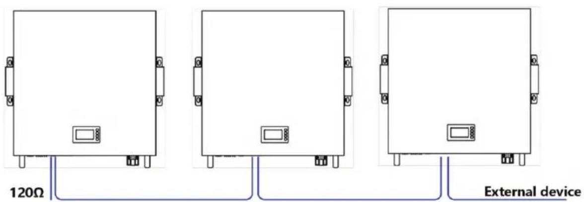
Figure 6-8 Connect the 120Ω Resistor
6.5.4 Set Dial Address
Assign addresses to battery packs by dialing the dialing keys of the dialing switch. DIP switch address please refer to "Table 5-5 Correspondence between BMS and DIP switch".
A. When the battery and the external device use the CAN communication mode, the battery connected to the external device is set to 0, and the other packs are set to 1/2/3 in sequence.
B. When the battery and the external device use the RS485 communication mode, the battery connected to the external device is set to 1, and the other packs are set to 2/3/4 in sequence.
ATTENTION
- Wear safety protection equipment to prevent electric shock from causing electric shock injuries.
- Use insulated tools to avoid electric shock.
- Communication cables and power cables must be laid separately.
- Before connecting cables, make sure that the bus-bars at the user end are in disconnected state.
- Pay attention to the polarity of the battery pack.
7 Power On
7.1 Power-on Operation (For professionals)
7.1.1 Power-on Check
1 Power on the charger/inverter at the user terminal.
2 Set the battery switch to ON (if available).
3 Observe RUN/ALM indicator and judge the battery operating status. If the RUN indicator of the battery is on and the ALM indicator is off, indicating that the battery is working normally. Otherwise indicating the battery is not work, you need to reconfirm whether the cable is connected well.
4 Please configure the actual number of batteries in parallel connection through the UIWare. As follows.

NOTE
- This section is for professionals only and requires specific tools and software. Currently only open to supplier accredited engineers.
7.1.2 UIWare Configuration
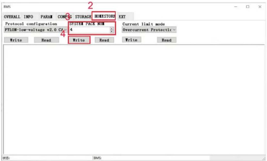
Figure 7-1 Configuration Page
1 Connect the UIWare by computer successfully.
2 Click the 'HOMESTORE' page.
3 Select the actual number of batteries in parallel connection on the 'SYSTEM PACK SUM'
4 Click the 'Write' button to finish the setting.
5 Restart the battery.

NOTE
- Please refer to the "UIWare User Manual" for more UIWare operations.
7.2 Power System Parameter Setting
Table 7-1 Parameter Setting
| No. | Parameters | Units | Standard Value |
| 16S | |||
| 1 | Rated voltage | V | 51.2 |
| 2 | Float charge voltage | V | 56.8 |
| 3 | Standard charge current | A | 0.2C |
| 4 | Max charge/discharge current | A | 1C |
| 5 | Condition to float charge | A | 0.05C |
| 6 | Charging operation temp | °C | 0~60°C |
| 7 | Discharging operation temp | °C | -20~60°C |
| 8 | RH | / | 10~95% |
NOTE
- The content in the table is just our suggestion, and actually need to refer to the customer's design requirements.
- The setting items of different chargers will be different.
- Follow strictly the power-on procedure to power on the battery pack, otherwise it will cause damage to the device or human body.
- Make sure the charger/Inverter is powered on before turning on the battery switch.
- Must not change the parameters casually in the site.
- Batteries will continue charge/discharge until BMS protection if there is communication fail or Lead-acid mode between battery and charger / Inverter.
- After batteries goes into the sleeping status, please turn on the battery switch against or press the reset button on the panel.
8.1 Shipment
It is suitable for the transportation of vehicles, ships and airplanes. During transportation, shading, sun protection and civilized loading and unloading should be performed. The box containing the product is allowed to be transported by any means of transportation. In the process of loading and unloading, the battery should be handled with care to prevent falling, rolling, and heavy pressure. Avoid direct rain and snow and mechanical impact during transportation.
And here is the suggestion for the initial SOC before shipment by different transportation:
- Airplane:30%\~40%
- Sea:50%\~60%
- Vehicle:50%\~60%
NOTE
- Whether the loading SOC status of the battery is allowed, you need to consult the relevant government transportation department.
8.2 Maintenance
8.2.1 Battery Maintenance Considerations
When maintaining the battery, it is required to use insulated tools or wrap the tools in insulation.
- DO NOT place any debris on the top of the battery.
- DO NOT use any organic solvents to clean the battery.
• DO NOT smoke or use naked flames near the battery.
• After the battery is discharged, the battery should be charged in time to avoid affecting the battery life. - When not using the battery for a long time, please charge the battery to 40%\~50% charged state. Long-term storage with low battery may damage the battery.
- All maintenance work must be carried out by professionals.
8 Shipment & Maintenance & Storage
8.2.2 Routine Maintenance
The staff should perform visual inspection on 48100E ESS series battery according to the inspection plan, please refer to the following table for maintenance.
Table 8-1 Routine Maintenance (Every three-month)
| Items | Standard | Dealing |
| Battery Appearance | The surface is neat and clean without stains.The terminals are in good condition.The battery pack shell is intact, and there is no bumps, breaks, or leakage.The appearance of the battery pack does not leak.No deformation or swelling of the shell. | If the surface is dirty, clean the appearance of the battery pack with a cotton cloth.The battery pack terminal is damaged, replace the cable.If the appearance is damaged, leaking or deformed, take a photo and replace the defective battery pack.Please contact supplier or the authorized dealers in time for other abnormal situations. |
| Alarm | No Alarm. | Find the solution as per alarm information. |

NOTE
- Suggested routine maintenance for every three-month.
Table 8-2 Routine Maintenance (Every six-month)
| Items | Standard | Action |
| (Suggested) Complete Cycle | Have a complete charge & discharge cycleunder the equipment no lack of power. | Check whether happens alarm action, and please check with the alarm list.Please contact with supplier or the authorized dealers if the alarm still exists. |
| Cables | There is no aging of the connecting wire and no cracking of the insulation layer.The bolts at the cable connection are not loose. | Replace the faulty connection.Fastening bolts. |
8.3 Battery Storage
- The recommended storage temperature is 15°C\~35°C.
- Battery performance degradation after long-term storage, please shorten shelf time as possible as you can.
- Recharge charge before using to recover capacity loss of self-discharge during storage and transport.
- Storage battery should be at 40%-50% SOC when the battery is not used for a long time.
- Storage battery over 40°C or under 0°C will reduce battery life.
• Storage battery in dry and low temperature, well ventilated place.
If the battery is not used for a long time, the battery must be charged at regular intervals. The charging requirements are as follows:
Table 8-3 Battery Charge Requirement in Storage Status
| Storage Temp. | Charge Period | Charge Process |
| 20°C~30°C | Each 6 months | 1.Charge by 0.2C to 100% SOC2.Discharge by 0.2C to 0% SOC3.Charge by 0.2C to 40%~50% SOC |
| 0°C~20°C or 30°C~40°C | Each 3 months |
Please refer to the table below to deal with common faults:
Table 9-1 FAQ
| Phenomenon | Possible cause | Solution |
| The indicator does not flash | The power cable of the battery pack is not properly connected.The power switch is off.The BMS is in a sleep state.BMS is damaged. | Reconnect the power cable of the battery pack.Turn on the power switch.Charge the battery pack.Replace BMS. |
| Unable to discharge | The terminal of the battery pack is damaged.BMS communication failure.The power switch is off. | Replace the battery pack wiring terminals.Reconnect the communication line between the BMS and the battery pack. If the communication cable is damaged, replace the communication cable.Turn on the power switch. |
| Unable to charge | The charger is malfunctioning.The terminal of the battery pack is damaged.BMS communication failure.The power switch is off. | Replace the charger.Replace the battery pack wiring terminals.Reconnect the communication line between the BMS and the battery pack. If the communication cable is damaged, replace the communication cable.Turn on the power switch. |
| Communication fail | The power switch is off.The BMS is in a sleep status.The communication cable is damage. | Turn on the power switch.Charge the battery pack.Replace the network cable. |
| Inaccurate voltage display | The voltage sampling line is damaged.BMS is damaged. | Replace the voltage sampling line.Replace BMS. |
| Low capacity | The battery pack has not been maintained for a long time.The single battery is damaged.Inaccurate voltage sampling. | Use an equalizer to maintain the battery pack.Replace the damaged single battery.Replace the electrical sampling line or replace the BMS. |
| Low cell voltage | The battery pack has not been maintained for a long time.The single battery is damaged.Inaccurate voltage sampling. | Use an equalizer to maintain the battery pack.Replace the damaged single battery.Replace the electrical sampling line or replace the BMS. |
10 Warranty
Except for the following and the conditions specified in the contract, you can go to the supplier or the authorized dealers for reasonable warranty and maintenance.
1 Failure of equipment caused by unauthorized disassembly and maintenance operations without the supplier or the authorized dealers is not within the scope of the warranty.
2 Equipment damage caused by negligence during storage and transportation is not covered by the warranty.
3 The damage to the equipment caused by continuous overload work outside the electrical parameters of the equipment is not covered by the warranty.
4 Unauthorized testing of the equipment without the supplier and the authorized dealers will not be covered by the warranty.
5 Non-equipment problems, adverse consequences caused by operation and matching problems are not covered by the warranty.
6 Equipment damage caused by natural forces, force majeure, and uncontrollable factors, such as earthquakes, typhoons, tornadoes, volcanic eruptions, floods, lightning, heavy snow, and wars, is not covered by the warranty.
7 If the product serial number is changed, blurred, or torn, it is not covered by the warranty.
11 Abbreviations
| BMS | Battery Management System |
| D | Depth |
| H | Height |
| W | Width |
| LCD | Liquid Crystal Display |
| LFP | LiFePO4 |
| MOSFET | Metal-Oxide-Semiconductor Field-Effect Transistor |
| NTC | Negative Temperature Coefficient |
| PC | Personal Computer |
| PCB | Printed Circuit Board |
| PCS | Power Conversion System |
| RTU | Remote Terminal Unit |
| SOC | State of Charge |


- INSTRUCTION MANUAL
- ESS SERIES BATTERY PACK
- INTRODUCTION
- Multi-Language Manual QR CODE
- Foreword
- Overview
- Reader
- Signs
- Safety Precautions
- Abuse Operation
- Product Description
- Features
- • High energy density
- - Maintenance-free
- - Long cycle life
- • Excellent temperature characteristics
- Basic Functions
- - Monitor
- - Alarm
- - Communication
- Overview
- • Parallel connection application
- • Balance function
- Application Scenario
- Parallel Connection Application
- Low-temperature Application
- • Low-temperature Charging
- • Low-temperature Discharging
- Low Battery-capacity Storage (SOC≤5%)
- Application Description
- Application of Nearing the Ocean
- NOTE
- Panel Introduction
- Panel Function
- Product Introduction
- Indicator Description
- DIP Address
- Communication Port Definition
- Installation
- Tools Preparation
- ATTENTION
- Unpacking and Inspection
- Preparing for Installation
- Installation
- Wall Mounting
- 6-2 Installation Space Requirement
- Cable Connection
- Power Cable Connection
- Communication Cable Connection
- 120Ω Resistor Connection
- Set Dial Address
- Power On
- Power-on Operation (For professionals)
- Power-on Check
- UIWare Configuration
- Power System Parameter Setting
- Shipment
- Maintenance
- Battery Maintenance Considerations
- Shipment & Maintenance & Storage
- Routine Maintenance
- Battery Storage
- Warranty
- Abbreviations
Brand : V-TAC
Model : VT-48100E
Category : Battery charger