
S6-EH3P10K2-H - Battery charger V-TAC - Free user manual and instructions
Find the device manual for free S6-EH3P10K2-H V-TAC in PDF.


| Product Type | Battery Charger |
| Brand | V-TAC |
| Model | S6-EH3P10K2-H |
| Input Voltage | AC 230V / 400V (3-phase) |
| Output Voltage | DC 48V (nominal) |
| Maximum Charging Current | 200A |
| Compatible Battery Types | Lead-acid, Lithium-ion, LiFePO4 |
| Dimensions (W x H x D) | 600 x 800 x 300 mm |
| Weight | 45 kg |
| Protection Features | Overvoltage, Overcurrent, Short Circuit, Reverse Polarity |
| Cooling Method | Forced air cooling with variable speed fan |
| Operating Temperature Range | -10°C to 50°C |
| Charging Stages | Bulk, Absorption, Float (for lead-acid); CC/CV (for lithium) |
| User Interface | LCD display with buttons |
| Communication Protocols | RS485, CAN bus, WiFi (optional) |
| Standards Compliance | CE, RoHS |
Frequently Asked Questions - S6-EH3P10K2-H V-TAC
User questions about S6-EH3P10K2-H V-TAC
0 question about this device. Answer the ones you know or ask your own.
Ask a new question about this device
Download the instructions for your Battery charger in PDF format for free! Find your manual S6-EH3P10K2-H - V-TAC and take your electronic device back in hand. On this page are published all the documents necessary for the use of your device. S6-EH3P10K2-H by V-TAC.
USER MANUAL S6-EH3P10K2-H V-TAC
for S6 Series Hybrid Inverter

Applicable models
S6-EH3P5K2-H
S6-EH3P6K2-H
S6-EH3P8K2-H
S6-EH3P10K2-H
S6-EH3P3K-H-EU
S6-EH3P4K-H-EU
S6-EH3P5K-H-EU
S6-EH3P6K-H-EU
S6-EH3P8K-H-EU
S6-EH3P10K-H-EU
S6-EH3P7K-H-LV
Applicable System
Three phase system
1. Introduction 02
1.1 Product Description 02
1.2 Packaging 03
2. Safety & Warning 04
2.1 Safety 04
2.2 General Safety Instructions 04
2.3 Notice For Use 06
2.4 Notice for Disposal 06
3. Overview 07
3.1 Intelligent LED Indicators 07
3.2 Password Reset 08
3.3 Inverter built-in Bluetooth description 08
4. Installation 09
4.1 Select a Location for the Inverter 09
4.2 Mounting the Inverter 10
4.3 PE Cable Installation 12
4.4 PV Input Cable Installation 13
4.5 Battery Power Cable Installation 16
4.6 AC Cable Installation 17
4.7 Communication Cable Installation 22
4.8 Meter Installation 27
4.9 Parallel System Wiring 30
4.10 Inverter Remote Monitoring Connection 31
5. Commissioning & Shutdown 32
5.1 Preparation of Commissioning 32
5.2 Commissioning Procedure 32
5.3 Shutdown Procedure 35
5.4 Work Mode 36
5.5 Parallel Settings 38
6. Maintenance 39
7. Troubleshooting 40
8. Specifications 45
1.1 Product Description
The Solis S6 Series is designed for residential hybrid systems, which can work with batteries to optimize self-consumption. The unit can operate in both off- and on-grid modes.
This manual covers the Solis S6 Series inverter model listed below:
S6-EH3P5K2-H, S6-EH3P6K2-H, S6-EH3P8K2-H, S6-EH3P10K2-H, S6-EH3P5K-H-EU,
S6-EH3P6K-H-EU, S6-EH3P8K-H-EU, S6-EH3P10K-H-EU, S6-EH3P7K-H-LV
The following models are exclusively for the Polish market:
S6-EH3P3K-H-EU, S6-EH3P4K-H-EU

Figure 1.1 Front side view
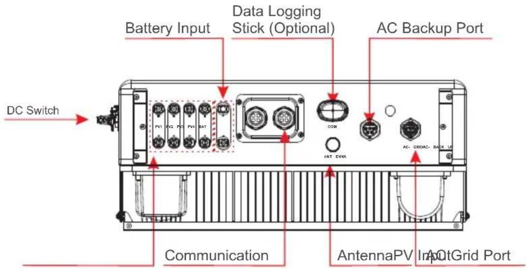
Figure 1.2 Bottom side view
1.2 Packaging
Please ensure that the following items are included in the packaging with your machine:

If anything is missing, please contact your local Solis distributor.
2.1 Safety
The following types of safety instructions and general information appear in this document as described below:

DANGER:
"Danger" indicates a hazardous situation which if not avoided, will result in death or serious injury.

WARNING:
"Warning" indicates a hazardous situation which if not avoided, could result in death or serious injury.

CAUTION:
"Caution" indicates a hazardous situation which if not avoided, could result in minor or moderate injury.

NOTE:
"Note" provides tips that are valuable for the optimal operation of your product.

WARNING: Risk of fire
Despite careful construction, electrical devices can cause fires.
- Do not install the inverter in areas containing highly flammable materials or gases.
- Do not install the inverter in potentially explosive atmospheres.
2.2 General Safety Instructions

WARNING:
Only devices in compliance with SELV (EN 69050) may be connected to the RS485 and USB interfaces.

WARNING:
Please don't connect PV array positive (+) or negative (-) to ground, it could cause serious damage to the inverter.

WARNING:
Electrical installations must be done in accordance with the local and national electrical safety standards.


WARNING:
Do not touch any inner live parts until 5 minutes after disconnection from the utility grid and the PV input.

WARNING:
To reduce the risk of fire, over-current protective devices (OCPD) are required for circuits connected to the inverter.
The DC OCPD shall be installed per local requirements. All photovoltaic source and output circuit conductors shall have that comply with isolators the NEC Article 690, Part II.

CAUTION:
Risk of electric shock, do not remove cover. There is no user serviceable parts inside, refer servicing to qualified and accredited service technicians.

CAUTION:
The PV array supplies a DC voltage when they are exposed to sunlight.

CAUTION:
The surface temperature of the inverter can reach up to 75° C (167 F). To avoid risk of burns, do not touch the surface of the inverter while it's operating. Inverter must be installed out of the reach of children.

NOTE:
PV module used with inverter must have an I EC 61730 Class A rating.

WARNING:
Operations below must be accomplished by licensed technician or Solis authorized person.

WARNING:
Operator must put on the technicians' gloves during the whole process in case of any electrical hazards.

WARNING:
AC BACKUP Port of S6 Series is not allowed to connect to the grid.

WARNING:
Please refer to the specification of the battery before configuration.
2.3 Notice for Use
The inverter has been constructed according to the applicable safety and technical guidelines. Use the inverter in installations that meet the following specifications ONLY:
- Permanent installation is required.
- The electrical installation must meet all the applicable regulations and standards.
- The inverter must be installed according to the instructions stated in this manual.
- The inverter must be installed according to the correct technical specifications.
2.4 Notice for Disposal
This product shall not be disposed of with household waste.
They should be segregated and brought to an appropriate collection point to enable recycling and avoid potential impacts on the environment and human health.
Local rules in waste management shall be respected.

3.1 Intelligent LED Indicators
There are five indicators on the Inverter (Battery, Power, WiFi, Ethernet and The Solis S6 Series Bluetooth) which indicate the working status of the inverter.
The Bluetooth Antenna or WiFi datalogger shall be installed at the Antenna/COM port of the hybrid inverter before local debugging.
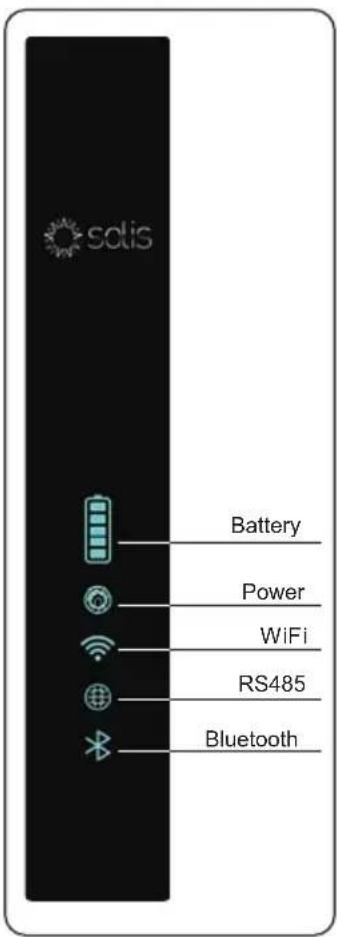
| Light Status Description | ||
| Battery | BlueFlashing every 3s | Battery discharging. |
| BlueFlashing every 1.5s | Battery charging. | |
| BlueSolid ON | Idle. | |
| OFF | No Battery or not working. | |
| Power | BlueSolid ON | Normally Operating. |
| YellowSolid ON | Warning. | |
| RedSolid ON or flashing every 3s | Alarm. | |
| OFF | No Battery or not working. | |
| WiFi | BlueSolid ON | COM Port is using. |
| OFF | COM Port is not used. | |
| RS485 | BlueSolid ON | RS485 Port is using. |
| OFF | RS485 Port is not used. | |
| Bluetooth | BlueSolid ON | Bluetooth Port is using. |
| OFF | Bluetooth Port is not used. | |
Turning On the LED Indicator Lights
After a few minutes, the LED indicator lights will turn off to conserve power.
To turn the lights back on, short-press the Inverter LED light.

Alarm State
When the inverter has an alarm, the Inverter LED light turns red and starts flashing. It is recommended to connect to the inverter with the Bluetooth tool. Then you can determine what the alarm code is.


NOTE:
Battery/WiFi/Ethernet/Bluetooth indicators will automatically turn off after 1 minute. The Power indicator will remain on with lower brightness. Short press the Power indicator can wake up all indicators.
3.2 Password Reset
When the password of the owner or the installer needs to be reset, please long press the Inverter indicator for 5s.
If the reset command is successfully triggered, the status indicator will be blue and blink for 3s at the frequency of 0.5s, then restore the original state of the indicator.
If the command fails to be triggered, the status indicator will be yellow and blink for 3s at the frequency of 0.5s, then restore the original state of the indicator.
If the command is successfully triggered, the Bluetooth password can be reset in the APP.
3.3 Inverter built-in Bluetooth description
Bluetooth: BDR、EDR、BLE
frequency band(s) in which the radio equipment operates:2400-2483.5MHZ
Maximum transmitting power: 4dBm
Hereby, Ginlong Technologies Co., Ltd. declares that the radio equipment type hybrid
inverter is in compliance with Directive 2014/53/EU
4.1 Select a Location for the Inverter
To select a location for the inverter, the following criteria should be considered:
- Exposure to direct sunlight may cause output power derating. It is recommended to avoid installing the inverter in direct sunlight.
- It is recommended that the inverter is installed in a cooler ambient which doesn't exceed 104°F/40°C.
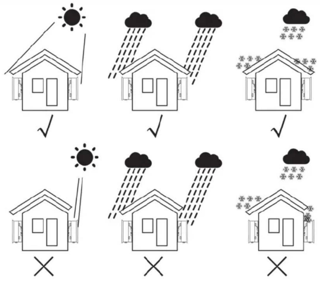
Figure 4.1 Recommended Installation locations

WARNING: Risk of fire
Despite careful construction, electrical devices can cause fires.
- Do not install the inverter in areas containing highly flammable materials or gases.
- Do not install the inverter in potentially explosive atmospheres.
- The mounting structure where the inverter is installed must be fireproof.
• Install on a wall or strong structure capable of bearing the weight of the machine (24kg).
• Install vertically with a maximum incline of +/- 5 degrees, exceeding this may cause output power derating.
• To avoid overheating, always make sure the flow of air around the inverter is not blocked. A minimum clearance of 200mm should be kept between inverters or objects and 200mm clearance between the bottom of the machine and the ground.

Figure 4.2 Inverter Mounting clearance
- Adequate ventilation must be provided.

NOTE:
Nothing should be stored on or placed against the inverter.
4.2 Mounting the Inverter
Dimensions of mounting bracket:
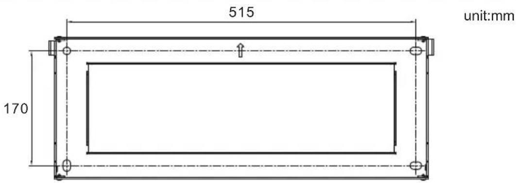
Figure 4.3 Inverter wall mounting
Once a suitable location has been found accordingly to 4.1 using figure 4.3 mount the wall bracket to the wall.
The inverter shall be mounted vertically.
The steps to mount the inverter are listed below:
-
Select the mounting height of the bracket and mark the mounting holes. For brick walls, the position of the holes should be suitable for the expansion bolts.
-
Lift up the inverter (be careful to avoid body strain), and align the back bracket on the inverter with the convex section of the mounting bracket. Hang the inverter on the mounting bracket and make sure the inverter is secure (see Figure 4.4)
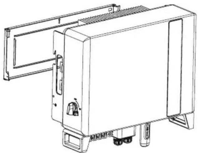
Figure 4.4 Wall Mount Bracket

WARNING:
The inverter must be mounted vertically.
4.3 PE Cable Installation
An external ground connection is provided at the right side of inverter.
Prepare OT terminals: M4. Use proper tooling to crimp the lug to the terminal.
Connect the OT terminal with ground cable to the right side of inverter. The torque is 2N.m.

Figure 4.5 Connect the external grounding conductor
4.4 PV Input Cable Installation

Before connecting inverter, please make sure the PV array open circuit voltage is within the limit of the inverter.

Before connection, please make sure the polarity of the output voltage of PV array matches the "DC+" and "DC-" symbols.

Please use approved DC cable for PV system.
- Select a suitable DC cable and strip the wires out by 7 ± 0.5 mm. Please refer to the table below for specific specifications.

| Cable type | Cross section (mm2) | |
| Range | Recommended value | |
| Industry generic P V cable | 4.0~6.0(12~10AWG) | 4.0 (12AWG) |
Figure 4.6
- Take the DC terminal out of the accessory bag, turn the screw cap to disassemble it, and take out the waterproof rubber ring.
Positive terminal
Negative terminal


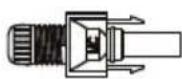


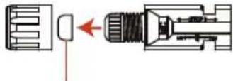
Nut Waterproof collar
Figure 4.7
- Pass the stripped DC cable through the nut and waterproof rubber ring.

- Connect the wire part of the DC cable to the metal DC terminal and crimp it with a special DC terminal crimping tool.
![graph LR A["Positive terminal"] --> B["Arrow pointing to a connector"] C["Negative terminal"] --> D["Arrow pointing to a connector"] B --> E["Squeeze"] D --> E style A fill:#f9f,stroke:#333 style C fill:#f9f,stroke:#333 style E fill:#ccf,stroke:#333](/content/2026/05/1088508/images/0b8cc29413d2cee097f187a3199561cd8c4abaef868a2befa5f35f0fc3bece37.jpg)
- Insert the crimped DC cable into the DC terminal firmly, then insert the waterproof rubber ring into the DC terminal and tighten the nut.
![graph TD A["Positive terminal"] --> B["Arrow to presser"] C["Negative terminal"] --> D["Arrow to presser"] B --> E["Arrow to presser"] D --> F["Arrow to presser"] E --> G["After you hear a "click", pull gently to check for a firm engagement."] F --> H["Click"] G --> I["Tighten"] H --> J["F…](/content/2026/05/1088508/images/c5d4d5c67be69b812485e73cca6721e9ca4eb2d4869a77372fb3a99845cd3e41.jpg)
- Measure PV voltage of DC input with multimeter, verify DC input cable polarity.
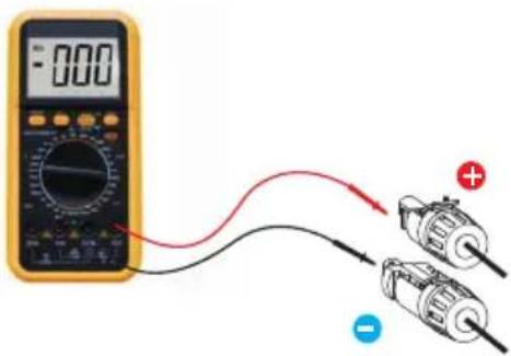
Figure 4.11
- Connect the wired DC terminal to the inverter as shown in the figure, and a slight "click" is heard to prove the connection is correct.

Figure 4.12

CAUTION:
If DC inputs are accidentally reversely connected or inverter is faulty or not working properly, it is NOT allowed to turn off the DC switch. Otherwise it may cause DC arc and damage the inverter or even lead to a fire disaster. The correct actions are:
*Use a clip-on ammeter to measure the DC string current.
*If it is above 0.5A, please wait for the solar irradiance reduces until the current decreases to below 0.5A.
*Only after the current is below 0.5A, you are allowed to turn off the DC switches and disconnect the PV strings.
* In order to completely eliminate the possibility of failure, please disconnect the PV strings after turning off the DC switch to aviod secondary failures due to continuous PV energy on the next day.
Please note that any damages due to wrong operations are not covered in the device warranty.
4.5 Battery Power Cable Installation
- Take out the two battery connectors from the package and crimp them as shown in the Figure 4.13.

Figure 4.13
The battery connection terminal size: 10mm 2 /8AWG
- Connect the battery ends to the battery module positive and negative terminals.
- Measure DC voltage of DC input with multimeter, verify DC input cable polarity.

Figure 4.14
- Connect the inverter end to the battery input port of the inverter as shown below, and push it in until you hear a "Click" sound which proves the fastened connection.

Figure 4.15
4.6 AC Cable Installation
There are two AC terminals on the inverter and the assembly steps are similar.
AC Grid Port is to connect to the grid and AC Backup Port is to connect to the critical load circuit.
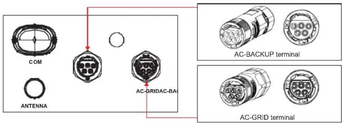
Figure 4.16

NOTE:
AC Backup Connector is longer while the AC Grid Connector is shorter.
4.6.1 AC Grid Port Connection
| Describe | Numerical value |
| Cable diameter | 14~17mm |
| Traverse cross sectional area | 6mm 2 |
| Exposure Length | 7mm |
Table 4.1
- Strip the AC wires about 7mm.

Figure 4.17
- Disassemble the AC Grid Connector and set the parts on the cable.
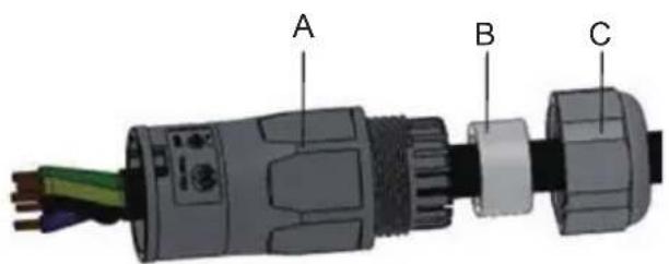
Figure 4.18
A: Body
B: Seal body
C: Nut
- Crimp wires, screw torque 0.8N·m±0.1N·m.


Figure 4.19
- Push Housing into Body until you hear a "click" sound.

Figure 4.20
- Insert Seal Body and Claw into the Body, and then tighten the Nut with torque 2.5N · m ± 0.5N · m .

Figure 4.21
- Push the AC Grid Connector into the AC Grid Port on the inverter and rotate the rotatory ring on the AC Grid connector to the direction as marked "LOCK" on the connector. (Hold the Body while rotating the ring).
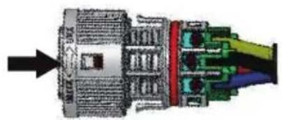

Figure 4.22

NOTE:
A continuity test shall be made to ensure that the correct terminations have been made after field wiring.
4.6.2 AC Backup Port Connection
| Describe | Numerical value |
| Cable diameter | 14~17mm |
| Traverse cross sectional area | 6mm 2 |
| Exposure Length | 7mm |
Table 4.2
- Strip the AC wires about 7mm.

Figure 4.23
- Disassemble the AC Backup Connector and set the parts on the cable.

Figure 4.24
A: Body
B: Seal body
C: Nut
- Crimp wires, screw torque 0.8N·m±0.1N·m.


AC Backup
Figure 4.25
- Push Housing into Body until you hear a "click" sound.
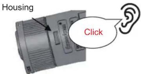
Figure 4.26
- Insert Seal Body and Claw into the Body, and then tighten the Nut with torque 2.5N · m ± 0.5N · m .

Figure 4.27
- Push the AC Backup Connector into the AC Backup Port on the inverter and rotate the rotatory ring on the AC Backup connector to the direction as marked "LOCK" on the connector. (Hold the Body while rotating the ring).


Figure 4.28

NOTE:
A continuity test shall be made to ensure that the correct terminations have been made after field wiring.
4.6.3 Disassembly Connector
- Separate the male and female connector, rotate the locker according to the direction instructed by the marks on the locker.

Figure 4.29
- Disassembling body and housing for rewire.

Figure 4.30
4.7 Communication Cable Installation
4.7.1 Protective Cover for Communication Ports

Figure 4.31
Inverter in the package is with a protective cover assembled to protect the communication ports.
Step 1. Use Phillips screwdriver to take out the 4 screws on the cover.
Step 2. Read through the following sections of the manual and prepare the internet cables correspondingly.
Step 3. Loose the cable gland and remove the watertight caps inside the cable gland based on the number of the cables and keep the unused holes with watertight cap.
Step 4. Lead the cables into the holes in the cable gland. (Hole Diameter: 6mm)
Step 5. Crimp the RJ45 connectors onto the cables according to the pin definitions described in the following sections and connect to the ports accordingly.
Step 6. Fasten the 4 screws on the cover (Torque: 1.7N.m-2 N.m)
Step 7. Reassemble the cable gland and ensure there is no bending or stretching of the internet cables inside the cover.

NOTE:
The 4-hole fastening rings inside the cable gland are with openings on the side.
Please separate the gap with hand and squeeze the cables into the holes from the side openings.

4.7.2 Communication Port Definition

Figure 4.32
| Port | Function |
| BMS | Used for CAN communication between inverter and Lithium battery BMS. |
| Meter | Used for RS485 communication between inverter and the smart meter. It is necessary to realize the normal hybrid control logics. |
| DRM | (Optional)To realize Demand Response or Logic interface function, this function may be required in UK and Australia. |
| RS485 | (Optional) Used for Modbus RTU communication with 3rd party external device or controller. |
| P-A/P-B | (Optional) Parallel operation communication ports (Reserved). |
| DO/DI | (Optional) Dry contact port (Reserved).Only generators with the dry contact function are supported for generator control. |
Table 4.3
4.7.3 BMS Port Connection
Take out the pre-made CAN cable from the package and connect one end to battery CAN port and then connect another end to the inverter BMS port.
Cable Length: 3 meters.

Figure 4.33

NOTE:
Pin definition of the BMS Port is following EIA/TIA 568B.
CAN-H on Pin 4: Blue
CAN-L on Pin 5: Blue/White

4.7.4 Meter Port Connection
Take out the pre-made Meter cable from the package and connect RJ45 end to inverter Meter port and then connect another end with loose RS485 A & B pins to the meter RS485 terminal.
Cable Length: 5 meters.

Figure 4.34

NOTE:
Pin definition of the Meter Port is following EIA/TIA 568B.
RS485A on Pin Orange/white1:
RS485B on Pin Orange2:
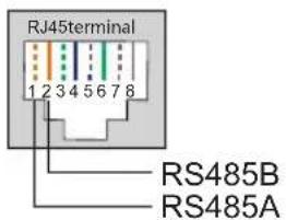

NOTE:
Compatible Smart Meter Pin definition.
Eastron SDM630MCT - Pin 13 is RS485B & Pin 14 is RS485A.
Eastron SDM630 - Pin B is RS485B & Pin A is RS485A.
4.7.5 DRM Port Connection (Optional)
4.7.5.1 For Remote Shutdown Function
Solis inverters support remote shutdown function to remotely control the inverter to power on and off through logic signals.
The DRM port is provided with an RJ45 terminal and its Pin5 and Pin6 can be used for remote shutdown function.
| Signal | Function |
| Short Pin5 and Pin6 | Inverter Generates |
| Open Pin5 and Pin6 | Inverter Shutdown in 5s |
Table 4.4
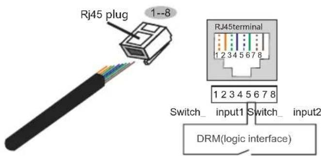
Correspondence between the cables and the stitches of plug, Pin5 and Pin6 of RJ45 terminal is used for the logic interface, other Pins are reserved.
Pin 1: Reserved; Pin 2: Reserved
Pin 3: Reserved; Pin 4: Reserved
Pin 5: Switch_input1; Pin 6: Switch_input2
Pin 7: Reserved; Pin 8: Reserved
Figure 4.35 Strip the insulation layer and connect to RJ45 plug
4.7.5.2 For DRED Control Function (For AU and NZ Only)
DRED means demand response enable device. The AS/NZS 4777.2 required :2020 inverter need to support demand response mode(DRM).
This function is for inverter that comply with AS/NZS 4777.2 standard.:2020 A RJ45 terminal is used for DRM connection.
| Pin | Assignment for inverters capable of both charging and discharging | Pin | Assignment for inverters capable of both charging and discharging |
| 1 | DRM 1/5 | 5 | RefGen |
| 2 | DRM 2/6 | 6 | Com/DRM0 |
| 3 | DRM 3/7 | 7 | V+ |
| 4 | DRM 4/8 | 8 | V- |
Table 4.5

NOTE:
Solis hybrid inverter is designed to provide 12V power for DRED.

Correspondence between the cables and the stitches of plug
Pin 1: white and orange ; Pin 2: orange
Pin 3: white and green; Pin 4: blue
Pin 5: white and blue; Pin 6: green
Pin 7: white and brown; Pin 8: brown
Figure 4.36 Strip the insulation layer and connect to RJ45 plug
4.7.6 RS485 Port Connection (Optional)
If a 3rd party external device or controller needs to communicate with the inverter, the RS485 port can be used. Modbus RTU protocol is supported by Solis inverters. To acquire latest protocol document, please contact Solis local service team or Solis sales.

NOTE:
Pin definition of the RS485 Port is following EIA/TIA 568B.
RS485A on Pin 5: Blue/White
RS485B on Pin 4: Blue

4.7.7 Parallel Terminal Connection (Optional)
Up to 6 units of the inverter can be connected in parallel.
Please connect the paralleled inverters in daisy chain by using P-A and P-B terminals.
Standard CAT5 with shielding layers internet cable can be used.

Figure 4.37 Parallel Terminal Connection
4.8 Meter Installation

CAUTION:
Make sure the AC cable is totally isolated from AC power before connecting the Smart Meter and CT.
The Solis S6-EH3P(3-10)K-H Series inverter is able to connected standard
Eastron meters to fulfill the control logic of the self-consumption mode, export power control, monitoring, etc.
Eastron 3ph meter (With CT): SDM630MCT (Provided by default)
Eastron 3ph meter (Direct Insert): SDM630 (Optional, Customer prepare if needed)

NOTE:
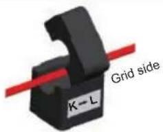
Please note that the CT orientation must be correct, otherwise the system will not work properly.
| Compatible Smart Meter Model | Meter RS485 Pin Definition |
| SDM630MCT | Pin 13 – RS485B, Pin 14 – RS485A |
| SDM630 | B – RS485B, A – RS485A |
Table 4.6
![graph TD A["PV strings"] --> B["CB"] B --> C["S6-EH3P(3-10)K-H-EU"] D["Battery"] --> E["CB"] E --> F["RS485"] G["Back-up"] --> H["L 3"] G --> I["L 2"] G --> J["L 1"] G --> K["N"] G --> L["PE"] M["Distribution box"] --> N["CB"] M --> O["RCD"] M --> P["Critical Load"] Q["Power cable"] --> R["Grid side…](/content/2026/05/1088508/images/06bd32e2a00e7108e1f49f811b33eb7a73fbd8ac3461e35f3522ce2272fb9fcb.jpg)
Figure 4.38 Eastron SDM630MCT
Note: If the CT is installed in the wrong direction, the Hybrid Inverter can't work normally.
![graph TD A["PV strings"] --> B["CB"] B --> C["S6-EH3P(3-10)K-H-EU"] C --> D["Back-up L3"] D --> E["C9"] E --> F["RCD"] F --> G["L3"] G --> H["Critical Load"] I["Battery"] --> J["CB"] J --> K["S6-EH3P(3-10)K-H-EU"] K --> L["N"] L --> M["PE"] M --> N["Grid"] O["RS485"] --> P["C8"] P --> Q["RCD"] Q -->…](/content/2026/05/1088508/images/8ce8f2e0d4bf6b291165b779a2b95318d0441e3d8a137d10bf0e259524a169d0.jpg)
Figure 4.39 Eastron SDM630
4.9 Parallel System Wiring
![graph TD subgraph Inverter_1 (Master) A1["Battery"] end subgraph Inverter_2 (Slave) B1["Battery"] end subgraph Inverter_3 (Slave) C1["Battery"] end subgraph Inverter_1 (Master) D1["L1 Wire"] D2["L2 Wire"] D3["L3 Wire"] D4["N Wire"] D5["PE Wire"] D6["CAN Wire/Parallel Wire"] D7["DC Wire"] end subgrap…](/content/2026/05/1088508/images/000eabe98b116dc109cd4251be47d7788c3ef2b1172dbf1f0072ba889cded065.jpg)
Figure 4.40
4.10 Inverter Remote Monitoring Connection
The inverter can be remotely monitored via WiFi, LAN or 4G.
The USB type COM port at the bottom of the inverter can connect to different kinds of Solis data loggers to realize the remote monitoring on Soliscloud platform.
To install Solis data loggers, please refer to corresponding user manuals of Solis data loggers.
The Solis data loggers are optional and can be purchased separately.
Dust cover is provided the inverter package in case the port is not used.

WARNING:
The USB type COM port is only allowed to connect Solis data loggers. It is forbidden to be used for other purposes.


COM
Figure 4.41

4G monitoring

WiFi monitoring

LAN monitoring

Router

Internet


APP


Soliscloud


Web server
Figure 4.42 Wireless communication function
5.1 Preparation of Commissioning
- Ensure all the devices are accessible for operation, maintenance and service.
- Check and confirm that the inverter is firmly installed.
• Space for ventilation is sufficient for one inverter or multiple inverters. - Nothing is left on the top of the inverter or battery module.
- Inverter and accessories are correctly connected.
- Cables are routed in safe place or protected against mechanical damage.
- Warning signs and labels are suitably affixed and durable.
- Bluetooth Antenna has been connected to the Antenna port of the inverter.
- An Android or IOS mobile phone with Bluetooth function is available.
- Soliscloud APP is installed on the mobile phone.
There are three ways to download and install the latest APP:
-
You can visit to download the latest www.soliscloud.com version APP.
-
You can search " " in Google Play or App Store.Soliscloud
-
You can scan this QR code below to download " ".Soliscloud

5.2 Commissioning Procedure
Step 1: Measure DC voltage of PV strings and battery and ensure the polarity is correct.
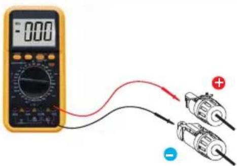
Step 2: Measure AC voltage and frequency and ensure they are within local standard.

Step 3: Switch on the external AC breaker to power on the inverter control board. (Bluetooth signal available)
Step 4: Connect with Bluetooth.
Turn on Bluetooth switch on your mobile phone and then open the Soliscloud APP.
Click "More Tools"->"Local Operation"->"Connect with Bluetooth"

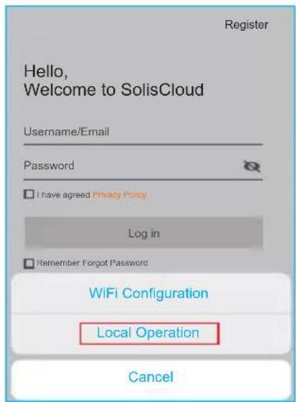
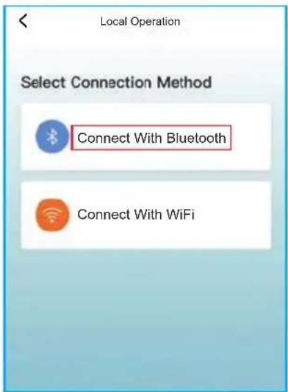
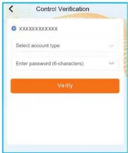
Step 5: Select the Bluetooth signal from the inverter. (Bluetooth Name: Inverter SN)

If you are the installer, please select the account type as Installer. If you are the plant owner, please select the account type as owner. Then set your own initial password for control verification. (The first log-in must be finished by installer in order to do the initial set up)


Step 7: After the log in for the first time, initial settings are required.
Step 7.1: Set the inverter Date and Time.
You can set to follow the time on your mobile phone.
Step 7.2: Set the battery model.
It must be based on the battery model that is actually connected to the inverter.
If there is no battery connected for the moment, please select "No Battery" to avoid alarms.
The default setting for battery over discharge SOC is 20%, force charge SOC is 10%.
Step 7.3: Set the meter setting.
It must be based on the meter type that is actually connected to the inverter.
If there is no meter connected for the moment, please select "No Meter" to avoid alarms.
It is suggested to install the meter at the system grid connection point and select "Meter in Grid".


Step 7.1 Step 7.2 Step 7.3
Step 7.4: Set the grid code setting.
Please select the grid code based on the local grid network requirements.
Step 7.5: Set the work mode setting.
Recommended setting is Self-Use Mode. This mode can maximize the use of PV power generation for household electricity, or store it in batteries and use it for household electricity. If need manually control the battery charging and discharging with respect to time, please use the Time of Use switch and the following set points. The “Allow Grid Charging” is recommended to be turned on (If turned off, the inverter will not force charge the battery and battery could potentially go to sleep).
![graph LR A["Inverter Time Meter Setting Work Mode"] --> B["G59/3"] A --> C["User-define"] A --> D["GREECE230"] A --> E["HK230"] A --> F["RENBLAD"] A --> G["CEI 0-16"] A --> H["NTS631"] A --> I["4777-A"]](/content/2026/05/1088508/images/6c9c922a13e301c80487b62e11c9dc26880fd9b8bb7ef20fe73026338202a07b.jpg)


Step 7.4 Step 7.5(1) Step 7.5(2)
Step 8: Setup complete.
Now the initial settings on the inverter have been set and you can switch on the inverter DC switch and switch on battery breaker to start up the system. You can also explore in the APP to check the operating data, alarm message or other advanced settings.
Step 9: Change Password.
If the Owner forgot the password, please contact the installer. Installer log in and go to "Setting"->"More"->"Change Password" to reset the password for owner's account.
If Installer forgot the password, please contact Solis service team.


5.3 Shutdown procedure
Step 1. Turn off the AC breaker at the grid connection point.
Step 2. Turn off the DC switch of the inverter.
Step 3. Turn off the battery breaker.
Step 4. Waiting for the device powered off and the system shutdown is completed.
5.4 Work mode
Self-Use Mode stores the excess PV power into the battery. If the battery is charged, or there is no battery, the excess PV power will be exported(sold) back to the utility company. If the system is set to not export any power, then the inverter will curtail the PV power(derate the inverter output power).
Feed in Priority Mode will ensure that the system exports any excess PV power after the home loads are supplied. If the export power quota has been met, then the remaining PV power will be stored in the battery. This mode should not be used if export power is going to be set to zero.
Off-Grid Mode is only to be used by systems that are not electrically connected to the grid at all. This mode is like Self-Use Mode, but the PV power will be curtailed if the battery is charged and the home load demand is lower than the amount of available PV power.
Peakshaving mode is possible to set the maximum power (Pmax) that the system obtains from the main grid. The power of the main grid charges batteries and supplies power to the load, which is within Pmax. When the load power exceeds the set maximum power (Pmax), the insufficient part is provided by the battery. At the same time, you can set the Peak SOC and charge the battery to this SOC as far as possible under the premise of satisfying Pmeter. The power of grid can be controlled to reduce the cost of electricity.
Time of Use Switch is for customizing when the battery is allowed to charge and discharge power and at what rate, established by a current(amperage)setting. If this slider switch is turned on, the inverter will only use this schedule to determine when to charge and discharge the battery. If Allow Grid Charging is turned on, the inverter will use grid power to charge the battery only under two circumstances:(1) the battery drains to the Force Charge SOC.
(2)Time of Use is enabled and there is not enough available PV power during the charge window to meet the current rate that is established.
Time of Use is for manual control of the battery charging/discharging. If Time of Use is turned off, charging/discharging is automatically regulated by the inverter.
| Self-Use Mode | |
| Self-Use Mode Switch | |
| Time of Use Switch | |
| Time of Use Charge Current Set | 50.0A > |
| Time of Use Discharge Current Set | 50.0A > |
| Charge Time Slot 1 | 22:00 - 08:00 > |
| Discharge Time Slot 1 | 08:00 ~ 22:00 > |
| Charge Time Slot 2 | 00:00 - 00:00 > |
| Discharge Time Slot 2 | 00:00 - 00:00 > |
| Charge Time Slot 3 | 00:00 - 00:00 > |
| Discharge Time Slot 3 | 00:00 - 00:00 > |
| Charge Time Slot 4 | 00:00 - 00:00 > |
| Discharge Time Slot 4 | 00:00 - 00:00 > |
| Charge Time Slot 5 | 00:00 - 00:00 > |
| Discharge Time Slot 5 | 00:00 - 00:00 > |
| Charge Time Slot 6 | 00:00 - 00:00 > |
| Discharge Time Slot 6 | 00:00 - 00:00 > |
| Allow Grid Charging | |
| Backup Mode Switch | |
| Reserved SOC | 80% > |
| < | Feed in Priority Mode |
| Feed in Priority Mode Switch | |
| Time of Use Switch | |
| Time of Use Charge Current Set | 135.0A > |
| Time of Use Discharge Current Set | 135.0A > |
| Charge Time Slot 1 | 00:00 ~ 01:00 > |
| Discharge Time Slot 1 | 01:00 ~ 02:00 > |
| Charge Time Slot 2 | 02:00 ~ 04:00 > |
| Discharge Time Slot 2 | 04:00 ~ 06:00 > |
| Charge Time Slot 3 | 06:00 ~ 10:00 > |
| Discharge Time Slot 3 | 10:00 ~ 11:00 > |
| Charge Time Slot 4 | 11:00 ~ 14:00 > |
| Discharge Time Slot 4 | 14:00 ~ 17:00 > |
| Charge Time Slot 5 | 17:30 ~ 18:00 > |
| Discharge Time Slot 5 | 18:00 ~ 22:55 > |
| Charge Time Slot 6 | 23:00 ~ 23:30 > |
| Discharge Time Slot 6 | 23:30 ~ 00:00 > |
| Allow Grid Charging | |
| Backup Mode Switch | |
| Reserved SOC | 80% > |
| Off-Grid Mode | |
| Off-grid Mode Switch | |
| Off-grid Overdischarge SOC | 30%> |
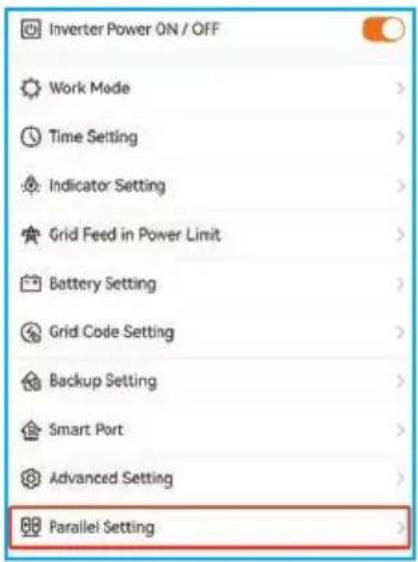
5.5 Parallel Settings
Set up a parallel system according to the following steps:
A. Set the parallel mode as "Parallel".
B. Set the master inverter address ID to 1, the other slaves to 2\~6.
(Note: the address ID cannot be set to 0, and the physical address of the master must be 1)
C. Choose "master" or "slave" for each inverter.
D. Choose the number of inverters in parallel, the range is 2\~6.
E. Enable "Parallel Sync", parameters of the main inverter will be synchronized to the slaves.
F. DIP Switch:
Option 1: Both the first and the last inverter(INV1 & INV3) have 1 of the DIP switch enabled. (Either Pin1 & Pin2)
Option 2: One of the first and the last inverter (INV1 or INV3) has 2 DIP switches enabled. (Both Pin1 or Pin2)

Solis S6 Series inverter does not require any regular maintenance. However, cleaning the heatsink will help inverter dissipating heat and increase the lifetime of inverter. The dirt on the inverter can be cleaned with a soft brush.

CAUTION:
Do not touch the surface when the inverter is operating. Some parts may be hot and cause burns. Turn OFF the inverter and let it cool down before you do any maintenance or cleaning of inverter.
The Screen and the LED status indicator lights can be cleaned with cloth if they are too dirty to be read.

NOTE:
Never use any solvents, abrasives or corrosive materials to clean the inverter.
| Message Name | Information Description | Troubleshooting Suggestion |
| Off Control device to shutdown | 1. Turn on the device in the ON/OFF Setting. | |
| LmtByEPM | The device's output is under controlled | 1. Confirm whether the inverter is connected to an external EPM/meter to prevent reverse current.2. Confirm whether the inverter is controlled by an external third-party device.3. Confirm whether the power setting of the inverter power control is limited.4. Verify settings in section 6.6.7 and check your meter readings. |
| LmtByDRM | DRM Function ON | 1. No need to deal with it. |
| LmtByTemp | Over temperature power limited | 1. No need to deal with it, the device is in normal operation. |
| LmtByFreq | Frequency power limited | |
| LmtByVg | The device is in the Volt-Watt mode | 1. Due to the requirements of local safety regulations, when the grid voltage is high, the Volt-watt working mode is triggered, which generally does not need to be dealt with.2. Inverter factory test errors causing this mode to open, if you need to close, you can close this mode in LCD, set the process: Main menu → Advanced Settings → Password 0010 → STD mode settings → Working Mode → Working mode: NULL → Save and exit. |
| LmtByVar | The device is in the Volt-Var mode of operation | 1. Due to the requirements of local safety regulations, when the grid voltage is high, the Volt-watt working mode is triggered, which generally does not need to be dealt with.2. Inverter factory test errors causing this mode to open, if you need to close, you can close this mode in LCD, set the process: Main menu → Advanced Settings → Password 0010 → STD mode settings → Working Mode → Working mode: NULL → Save and exit. |
| Surge Alarm On-site | grid surge | 1. Grid side fault, restart the device.If it is still not eliminated, please contact the manufacturer's customer service. |
| OV-G-V01 | Grid voltage exceeds the upper voltage range | 1. Confirm whether the power grid is abnormal.2. Confirm that the AC cable is properly connected.3. Restart the system and check if the fault persists. |
| UN-G-V01 | Grid voltage exceeds the lower voltage range | |
| OV-G-F01 | Grid frequency exceeds the upper frequency range | |
| UN-G-F01 | Grid frequency exceeds the lower frequency range | |
| G-PHASE | Unbalanced grid voltage | |
| G-F-G L U | Grid voltage frequency fluctuation | |
| NO-Grid | No grid | |
| OV-G-V02 | Grid transient overvoltage | |
| OV-G-V03 | Grid transient overvoltage | 1. Restart the system, confirm if that the fault continues. |
| IGFOL-F | Grid current tracking failure | 1. Confirm whether the power grid is abnormal.2. Confirm that the AC cable is properly connected.3. Restart the system and check if the fault persists. |
| OV-G-V05 | Grid voltage RMS instantaneous overvoltage fault | |
| OV-G-V04 | Grid voltage exceeds the upper voltage range | |
| UN-G-V02 | Grid voltage exceeds the lower voltage range | |
| OV-G-F02 | Grid frequency exceeds the upper frequency range | |
| UN-G-F02 | Grid frequency exceeds the lower frequency range | |
| NO-Battery | Battery is not connected | 1. Check on information page 1 - Verify the battery voltage is within standards.2. Measure battery voltage at plug. |
| OV-Vbackup | Inverting overvoltage | 1. Check whether the backup port wiring is normal2. Restart the system, confirm that the fault continues. |
| Over-Load | Load overload fault | 1. Backup load power is too large, or some inductive load startup power is too large, need to remove some backup load, or remove the inductive load on the backup. |
| BatName-FAIL | Wrong battery brand selection | 1. Confirm whether the battery model selection is consistent with the actual one. |
| CAN Fail CAN Fail | 1. Can failure is a failure of communication between inverter and battery. Check cable conditions. Check to ensure you have it plugged in on the CAN port of the battery and inverter. Check that you are using the right cable. Some batteries require a special battery from the battery manufacturer. | |
| OV-Vbatt | Battery overvoltage detected | 1. Verify battery voltage is within standards.Measure battery voltage at inverter connection point. Contact your battery manufacturer for further service. |
| UN-Vbatt | Battery undervoltage detected | 1. Restart the system and check if the fault persists. If it is still not eliminated, please contact the manufacturer's customer service. |
| Fan Alarm | Fan alarm | 1. Check if the internal fan is working correctly or jammed. |
| OV-DC01(1020 D ATA:0001) | DC 1 input overvoltage | 1. Check if the PV voltage is abnormal2. Restart the system, confirm that the fault continues |
| OV-DC02(1020 D ATA:0002) | DC 2 input overvoltage | |
| OV-BUS(1021 D ATA:0000) | DC bus overvoltage | 1. Restart the system, confirm that the fault continues. |
| UN-B U S01(1023 D ATA:0001) | DC bus undervoltage | |
| UNB-B US(1022 D ATA:0000) | DC bus unbalanced voltage | |
| UN-B U S02(1023 D ATA:0002) | Abnormal detection of DC bus voltage | |
| DC-I N TF.(1027 D ATA:0000) | DC hardware overcurrent (1, 2, 3, 4) | 1. Check if the DC wires are connected correctly without loose connection. |
| OV-G-I(1018 D ATA:0000) | A phase RMS value overcurrent | 1. Confirm that the grid is abnormal.2. Confirm that the AC cable connection is not abnormal.3. Restart the system, confirm that the fault continues. |
| OV-DCA-I(1025 D ATA:0000) | DC 1 average overcurrent | 1. Restart the system, confirm that the fault continues. |
| OV-DCB-I(1026 D ATA:0000) | DC 2 average overcurrent | |
| GRID-INTF.(1030 D ATA:0000) | AC hardware overcurrent (abc phase) | |
| DC Inj-FAULT(1037 DATA:0000) | The current DC component exceeds the limit | 1. Confirm that the grid is abnormal.2. Confirm that the AC cable connection is not abnormal.3. Restart the system, confirm that the fault continues. |
| IG BT-OV-I(1048 DATA:0000) | IGBT overcurrent | 1. Restart the system, confirm that the fault continues. |
| OV-TEM(1032 DATA:0000) | Module over temperature | 1. Check whether the surrounding environment of the inverter has poor heat dissipation.2. Confirm whether the product installation meets the requirements. |
| RelayChk-FAIL(1035 DATA:0000) | Relay failure | 1. Restart the system, confirm that the fault continues. |
| UN-TE M(103A DATA:0000) | Low temperature protection | 1. Check the working environment temperature of the inverter.2. Restart the system to confirm if the fault continues. |
| PV ISO-PRO01(1033 DATA:0001) | PV negative ground fault | 1. Check whether the PV strings have insulation problems.2. Check whether the PV cable is damaged. |
| PV ISO-PRO02(1033 DATA:0002) | PV positive ground fault | |
| 12Power-FAULT(1038 DATA:0000) | 12V undervoltage failure | 1. Check current leakage to ground.Verify your grounding.Verify all wires are in good condition and not leaking current to ground. |
| ILeak-PR O01(1034 DATA:0001) | Leakage current failure 01 (30mA) | |
| ILeak-PR O02(1034 DATA:0002) | Leakage current failure 02 (60mA) | |
| ILeak-PR O03(1034 DATA:0003) | Leakage current failure 03 (150mA) | |
| ILeak-PR O04(1034 DATA:0004) | Leakage current failure 04 | |
| ILeak_Check(1039 DATA:0000) | Leakage current sensor failure | |
| GR ID-IN TF02(1046 DATA:0000) | Power grid disturbance 02 | 1. Confirm whether the grid is seriously distorted.2. Check whether the AC cable is connected reliably. |
| OV-Vbatt-H/OV-BUS-H(1051 DATA:0000) | Battery overvoltage hardware failure / VBUS | 1. Check if the battery circuit breaker is tripping.2. Check if the battery is damaged. |
| OV-ILLC(1052 DATA:0000) | LLC hardware overcurrent | 1. Check whether the backup load is overloaded.2. Restart the system, confirm that the fault continues. |
| INI-FAULT(1031 DATA:0000) | AD zero drift overlink | 1. Restart the system, confirm that the fault continues. |
| DSP-B-FAULT(1036 DATA:0000) | The master-slave DSP communication is abnormal | |
| AFCI-Check(1040 DATA:0000) | AFCI self-test failure | |
| ARC- FAULT(1041 DATA:0000) | AFCI failure | 1. Verify connections are tight within your PV system. Arc fault settings can be changed in advanced settings if further adjustment is necessary. |
Table 7.1 Fault message and description

NOTE:
If the inverter displays any alarm message as listed in Table 7.1; please turn off the inverter and wait for 5 minutes before restarting it. If the failure persists, please contact your local distributor or the service center.
Please keep ready with you the following information before contacting us.
- Serial number of Solis Three Phase Inverter;
- The distributor/dealer of Solis Three Phase Inverter (if available);
- Installation date.
- The description of the problem together with necessary information, pictures, attachment.
- The PV array configuration (e.g. number of panels, capacity of panels, number of strings, etc.);
- Your contact details.
| Technical Data | S6-EH3P5K2-H | S6-EH3P6K2-H |
| Input DC (PV side) | ||
| Recommended max. PV power | 8000W | 9600W |
| Max. input voltage | 1000V | |
| Rated voltage | 600V | |
| Start-up voltage | 160V | |
| MPPT voltage range | 200-850V | |
| Full load MPPT voltage range | 250-850V | |
| Max. input current | 16A/16A | |
| Max. short circuit current 24A/24A | ||
| MPPT number/Max input strings number | 2/2 | |
| Max input power per MPPT | 9000W8000W | |
| Battery | ||
| Battery Type | Li-ion | |
| Battery Voltage range | 120 - 600Vdc | |
| Maximum charging Power | 5kW | 6kW |
| Maximum Charge/discharge current | 25A | |
| Communication | CAN/RS485 | |
| Output AC(Grid-side) | ||
| Rated output power | 5kW | 6kW |
| Max. apparent output power | 5kVA | 6kVA |
| Rated grid voltage | 3/N/PE, 380V/400V | |
| The grid voltage range | 320-460V | |
| Rating grid frequency | 50 Hz/60 Hz | |
| AC grid frequency range | 45-55 Hz/ 55-65Hz | |
| Rating grid output current | 7.6A/7.2A 9.1A/8.7A | |
| Max. output current | 7.6A/7.2A 9.1A/8.7A | |
| Power factor | >0.99 (0.8 leading to 0.8 lagging) | |
| TH Di | <3% | |
| Technical Data | S6-EH3P5K2-H S6-EH3P6K2-H | |
| Input AC(Grid-side) | ||
| Input voltage range | 304-437V / 320-460V | |
| Max. input current | 11.4A | 13.8A |
| Rated grid frequency | 50 Hz/60 Hz | |
| Frequency range | 45-55 Hz / 55-65 Hz | |
| Output AC(Back-up) | ||
| Rated output power | 6kW5kW | |
| Peak apparent output power | 8.0kVA, 60 sec | 9.6kVA, 60 sec |
| Back-up switch time | < 10ms | |
| Rated output voltage | 3/N/PE, 380V/400V | |
| Rated frequency | 50 Hz/60 Hz | |
| Rated output current | 7.6A/7.2A 9.1A/8.7A | |
| THDv(@linear load) | <2% | |
| Efficiency | ||
| PV Max. efficiency | 96.50% | 97.00% |
| EU efficiency | 96.77% | 97.10% |
| BAT charged by PV Max. efficiency | 98.37% | 98.45% |
| BAT charged/discharged to AC Max. efficiency | 97.32% | 97.34% |
| Protection | ||
| Anti-islanding protection | Yes | |
| Integrated AFCI 2.0 | Optional | |
| Insulation Resistor detection | Yes | |
| Residual current monitoring unit | Yes | |
| Output over current protection | Yes | |
| Output short protection | Yes | |
| Output over voltage protection | Yes | |
| DC switch | Yes | |
| DC reverse polarity protection | Yes | |
| PV overvoltage protection | Yes | |
| Battery reverse protection | Yes | |
| Technical Data | S6-EH3P5K2-H S6-EH3 P6K2-H |
| General data | |
| Max. allowable phase imbalance (grid & back up) | 100% |
| Max. power per phase (grid & back up) | 50% rated power |
| Dimensions(W/H/D) | 600*500*210mm |
| Weight | 27.58kg |
| Topology | Transformerless |
| Self consumption (Night) | <25 W |
| Operation temperature range | -25°C ~ +60°C |
| Relative humidity | 0-95% |
| Ingress protection | IP66 |
| Noise emission | <46.9 dB(A) |
| Cooling concept | Natural convection |
| Max.operation altitude | 4000m |
| Grid connection standard | G98 or G99, VDE-AR-N 4105 / VDE V 0124, EN 50549-1, VDE 0126 / U TE C 15/VFR:2019, RD 1699/R D 244 / UNE 206006 / UNE 206007-1, CEI 0-21, C10/11, NRS 097-2-1, TOR, EIFS 2018.2, I EC 62116, IEC 61727, IEC 60068, IEC 61683, EN 50530, MEA, PEA |
| Safty/EMC standard | IEC 62109-1/-2 ,EN 61000-6-1/-3 |
| Features | |
| PV connection | MC4 connector |
| Battery connection | Quick Connection plug |
| AC connection | Quick Connection plug |
| Display | LED indicator & Bluetooth+APP |
| Communication | CAN, RS485, Optional:Wi-Fi, Cellular, LAN |
| Warranty | 5 years (extend to 20 years) |
| Technical Data | S6-EH3P8K2-H | S6-EH3P10K2-H |
| Input DC (PV side) | ||
| Recommended max. PV power | 12800W | 16000W |
| Max. input voltage | 1000V | |
| Rated voltage | 600V | |
| Start-up voltage | 160V | |
| MPPT voltage range | 200-850V | |
| Full load MPPT voltage range | 300-850V | 350-850V |
| Max. input current | 16A/16A | |
| Max. short circuit current 24A/24A | ||
| MPPT number/Max input strings number | 2/2 | |
| Max input power per MPPT | 9000W9000W | |
| Battery | ||
| Battery Type | Li-ion | |
| Battery Voltage range | 120 - 600Vdc | |
| Maximum charging Power | 8kW | 10kW |
| Maximum Charge/discharge current | 50A | |
| Communication | CAN/RS485 | |
| Output AC(Grid-side) | ||
| Rated output power | 8kW | 10kW |
| Max. apparent output power | 8kVA | 10kVA |
| Rated grid voltage | 3/N/PE, 380V/400V | |
| The grid voltage range | 320-460V | |
| Rating grid frequency | 50 Hz/60 Hz | |
| AC grid frequency range | 45-55 Hz/ 55-65Hz | |
| Rating grid output current | 12.2A/11.5A 15.2A/14.4A | |
| Max. output current | 12.2A/11.5A 15.2A/14.4A | |
| Power factor | >0.99 (0.8 leading to 0.8 lagging) | |
| TH Di | <3% | |
| Technical Data | S6-EH3P8K2-H S6-EH3P10K2-H | |
| Input AC(Grid-side) | ||
| Input voltage range | 304-437V / 320-460V | |
| Max. input current | 18.2A | 22.8A |
| Rated grid frequency | 50 Hz/60 Hz | |
| Frequency range | 45-55 Hz / 55-65 Hz | |
| Output AC(Back-up) | ||
| Rated output power | 10kW8kW | |
| Peak apparent output power | 12.8kVA, 60 sec | 16kVA, 60 sec |
| Back-up switch time | < 10ms | |
| Rated output voltage | 3/N/PE, 380V/400V | |
| Rated frequency | 50 Hz/60 Hz | |
| Rated output current | 12.2A/11.5A 15.2A/14.4A | |
| THDv(@linear load) | <2% | |
| Efficiency | ||
| PV Max. efficiency | 97.50% | 97.90% |
| EU efficiency | 97.41% | 97.51% |
| BAT charged by PV Max. efficiency | 98.22% | 98.31% |
| BAT charged/discharged to AC Max. efficiency | 97.50% | 97.50% |
| Protection | ||
| Anti-islanding protection | Yes | |
| Integrated AFCI 2.0 | Optional | |
| Insulation Resistor detection | Yes | |
| Residual current monitoring unit | Yes | |
| Output over current protection | Yes | |
| Output short protection | Yes | |
| Output over voltage protection | Yes | |
| DC switch | Yes | |
| DC reverse polarity protection | Yes | |
| PV overvoltage protection | Yes | |
| Battery reverse protection | Yes | |
| Technical Data | S6-EH3P8K2-H S6-EH3P10K2-H |
| General data | |
| Max. allowable phase imbalance (grid & back up) | 100% |
| Max. power per phase (grid & back up) | 50% rated power |
| Dimensions(W/H/D) | 600*500*230mm |
| Weight | 30.18kg |
| Topology | Transformerless |
| Self consumption (Night) | <25 W |
| Operation temperature range | -25°C ~ +60°C |
| Relative humidity | 0-95% |
| Ingress protection | IP66 |
| Noise emission | <46.9 dB(A) |
| Cooling concept | Natural convection |
| Max.operation altitude | 4000m |
| Grid connection standard | G98 or G99, VDE-AR-N 4105 / VDE V 0124, EN 50549-1, VDE 0126 / U TE C 15/VFR:2019, RD 1699/R D 244 / UNE 206006 / UNE 206007-1, CEI 0-21, C10/11, NRS 097-2-1, TOR, EIFS 2018.2, IEC 62116, IEC 61727, IEC 60068, IEC 61683, EN 50530, MEA, PEA |
| Safty/EMC standard | IEC 62109-1/-2 ,EN 61000-6-1/-3 |
| Features | |
| PV connection | MC4 connector |
| Battery connection | Quick Connection plug |
| AC connection | Quick Connection plug |
| Display | LED indicator & Bluetooth+APP |
| Communication | CAN, RS485, Optional:Wi-Fi, Cellular, LAN |
| Warranty | 5 years (extend to 20 years) |
| Technical Data | S6-EH3P3K-H-EU | S6-EH3P4K-H-EU |
| Input DC (PV side) | ||
| Recommended max. PV power | 4800W | 6400W |
| Max. input voltage | 1000V | |
| Rated voltage | 600V | |
| Start-up voltage | 160V | |
| MPPT voltage range | 200-850V | |
| Full load MPPT voltage range | 200-850V | |
| Max. input current | 16A/16A | |
| Max. short circuit current 24A/24A | ||
| MPPT number/Max input strings number | 2/2 | |
| Max input power per MPPT | 6400W4800W | |
| Battery | ||
| Battery Type | Li-ion | |
| Battery Voltage range | 120 - 600Vdc | |
| Maximum charging Power | 3kW | 4kW |
| Maximum Charge/discharge current | 25A | |
| Communication | CAN/RS485 | |
| Output AC(Grid-side) | ||
| Rated output power | 3kW | 4kW |
| Max. apparent output power | 3kVA | 4kVA |
| Rated grid voltage | 3/N/PE, 380V/400V | |
| The grid voltage range | 320-460V | |
| Rating grid frequency | 50 Hz/60 Hz | |
| AC grid frequency range | 45-55 Hz/ 55-65Hz | |
| Rating grid output current | 4.6A/4.3A 6.1A/5.8A | |
| Max. output current | 4.6A/4.3A 6.1A/5.8A | |
| Power factor | >0.99 (0.8 leading to 0.8 lagging) | |
| TH Di | <3% | |
| Technical Data | S6-EH3P3K-H-EU S6-EH3P4K-H-EU | |
| Input AC(Grid-side) | ||
| Input voltage range | 304-437V / 320-460V | |
| Max. input current | 6.8A | 9.1A |
| Rated grid frequency | 50 Hz/60 Hz | |
| Frequency range | 45-55 Hz / 55-65 Hz | |
| Output AC(Back-up) | ||
| Rated output power | 4kW3kW | |
| Peak apparent output power | 4.8kVA, 60 sec | 6.4kVA, 60 sec |
| Back-up switch time | < 10ms | |
| Rated output voltage | 3/N/PE, 380V/400V | |
| Rated frequency | 50 Hz/60 Hz | |
| Rated output current | 4.6A/4.3A 6.1A/5.8A | |
| THDv(@linear load) | <2% | |
| Efficiency | ||
| PV Max. efficiency | 95.50% | 96.00% |
| EU efficiency | 95.51% | 96.03% |
| BAT charged by PV Max. efficiency | 95.96% | 96.57% |
| BAT charged/discharged to AC Max. efficiency | 97.04% | 97.29% |
| Protection | ||
| Anti-islanding protection | Yes | |
| Integrated AFCI 2.0 | Optional | |
| Insulation Resistor detection | Yes | |
| Residual current monitoring unit | Yes | |
| Output over current protection | Yes | |
| Output short protection | Yes | |
| Output over voltage protection | Yes | |
| DC switch | Yes | |
| DC reverse polarity protection | Yes | |
| PV overvoltage protection | Yes | |
| Battery reverse protection | Yes | |
| Technical Data | S6-EH3P3K-H-EU S6-EH3P4K-H-EU |
| General data | |
| Max. allowable phase imbalance (grid & back up) | 100% |
| Max. power per phase (grid & back up) | 50% rated power |
| Dimensions(W/H/D) | 600*500*210mm |
| Weight | 26.42kg |
| Topology | Transformerless |
| Self consumption (Night) | <25 W |
| Operation temperature range | -25°C ~ +60°C |
| Relative humidity | 0-95% |
| Ingress protection | IP66 |
| Noise emission | <46.9 dB(A) |
| Cooling concept | Natural convection |
| Max.operation altitude | 4000m |
| Grid connection standard | G98 or G99, VDE-AR-N 4105 / VDE V 0124, EN 50549-1, VDE 0126 / UTE C 15/VFR:2019, RD 1699/RD 244 / UNE 206006 / UNE 206007-1, CEI 0-21, C10/11, NRS 097-2-1, TOR, EIFS 2018.2, IEC 62116, IEC 61727, IEC 60068, IE C 61683, EN 50530, MEA, P EA |
| Safty/EMC standard | IEC 62109-1/-2 ,EN 61000-6-1/-3 |
| Features | |
| PV connection | MC4 connector |
| Battery connection | Quick Connection plug |
| AC connection | Quick Connection plug |
| Display | LED indicator & Bluetooth+APP |
| Communication | CAN, RS485, Optional:Wi-Fi, Cellular, LAN |
| Warranty | 5 years (extend to 20 years) |
| Technical Data | S6-EH3P5K-H-EU | S6-EH3P6K-H-EU |
| Input DC (PV side) | ||
| Recommended max. PV power | 8000W | 9600W |
| Max. input voltage | 1000V | |
| Rated voltage | 600V | |
| Start-up voltage | 160V | |
| MPPT voltage range | 200-850V | |
| Full load MPPT voltage range | 200-850V | |
| Max. input current | 16A/16A/16A | |
| Max. short circuit current 24A/24A/24A | ||
| MPPT number/Max input strings number | 3/3 | |
| Max input power per MPPT | 9000W8000W | |
| Battery | ||
| Battery Type | Li-ion | |
| Battery Voltage range | 120 - 600Vdc | |
| Maximum charging Power | 5kW | 6kW |
| Maximum Charge/discharge current | 25A | |
| Communication | CAN/RS485 | |
| Output AC(Grid-side) | ||
| Rated output power | 5kW | 6kW |
| Max. apparent output power | 5kVA | 6kVA |
| Rated grid voltage | 3/N/PE, 380V/400V | |
| The grid voltage range | 320-460V | |
| Rating grid frequency | 50 Hz/60 Hz | |
| AC grid frequency range | 45-55 Hz/ 55-65Hz | |
| Rating grid output current | 7.6A/7.2A 9.1A/8.7A | |
| Max. output current | 7.6A/7.2A 9.1A/8.7A | |
| Power factor | >0.99 (0.8 leading to 0.8 lagging) | |
| TH Di | <3% | |
| Technical Data | S6-EH3P5K-H-EU S6-EH3P6K-H-EU | |
| Input AC(Grid-side) | ||
| Input voltage range | 304-437V / 320-460V | |
| Max. input current | 11.4A | 13.8A |
| Rated grid frequency | 50 Hz/60 Hz | |
| Frequency range | 45-55 Hz / 55-65 Hz | |
| Output AC(Back-up) | ||
| Rated output power | 6kW5kW | |
| Peak apparent output power | 8.0kVA, 60 sec | 9.6kVA, 60 sec |
| Back-up switch time | < 10ms | |
| Rated output voltage | 3/N/PE, 380V/400V | |
| Rated frequency | 50 Hz/60 Hz | |
| Rated output current | 7.6A/7.2A 9.1A/8.7A | |
| THDv(@linear load) | <2% | |
| Efficiency | ||
| PV Max. efficiency | 96.50% | 97.00% |
| EU efficiency | 96.77% | 97.10% |
| BAT charged by PV Max. efficiency | 98.37% | 98.45% |
| BAT charged/discharged to AC Max. efficiency | 97.32% | 97.34% |
| Protection | ||
| Anti-islanding protection | Yes | |
| Integrated AFCI 2.0 | Optional | |
| Insulation Resistor detection | Yes | |
| Residual current monitoring unit | Yes | |
| Output over current protection | Yes | |
| Output short protection | Yes | |
| Output over voltage protection | Yes | |
| DC switch | Yes | |
| DC reverse polarity protection | Yes | |
| PV overvoltage protection | Yes | |
| Battery reverse protection | Yes | |
| Technical Data | S6-EH3P5K-H-EU S6-EH3P6K-H-EU |
| General data | |
| Max. allowable phase imbalance (grid & back up) | 100% |
| Max. power per phase (grid & back up) | 50% rated power |
| Dimensions(W/H/D) | 600*500*210mm |
| Weight | 27.58kg |
| Topology | Transformerless |
| Self consumption (Night) | <25 W |
| Operation temperature range | -25°C ~ +60°C |
| Relative humidity | 0-95% |
| Ingress protection | IP66 |
| Noise emission | <46.9 dB(A) |
| Cooling concept | Natural convection |
| Max.operation altitude | 4000m |
| Grid connection standard | G98 or G99, VDE-AR-N 4105 / VDE V 0124, EN 50549-1, VDE 0126 / UTE C 15/VFR:2019, RD 1699/RD 244 / UNE 206006 / UNE 206007-1, CEI 0-21, C10/11, NRS 097-2-1, TOR, EIFS 2018.2, IEC 62116, IEC 61727, IEC 60068, IEC 61683, EN 50530, MEA, P EA |
| Safty/EMC standard | IEC 62109-1/-2 ,EN 61000-6-1/-3 |
| Features | |
| PV connection | MC4 connector |
| Battery connection | Quick Connection plug |
| AC connection | Quick Connection plug |
| Display | LED indicator & Bluetooth+APP |
| Communication | CAN, RS485, Optional:Wi-Fi, Cellular, LAN |
| Warranty | 5 years (extend to 20 years) |
| Technical Data | S6-EH3P8K-H-EU | S6-EH3P10K-H-EU |
| Input DC (PV side) | ||
| Recommended max. PV power | 12800W | 16000W |
| Max. input voltage | 1000V | |
| Rated voltage | 600V | |
| Start-up voltage | 160V | |
| MPPT voltage range | 200-850V | |
| Full load MPPT voltage range | 200-850V | 250-850V |
| Max. input current | 16A/16A/16A/16A | |
| Max. short circuit current 24A/24A/24A/24A | ||
| MPPT number/Max input strings number | 4/4 | |
| Max input power per MPPT | 9000W9000W | |
| Battery | ||
| Battery Type | Li-ion | |
| Battery Voltage range | 120 - 600Vdc | |
| Maximum charging Power | 8kW | 10kW |
| Maximum Charge/discharge current | 50A | |
| Communication | CAN/RS485 | |
| Output AC(Grid-side) | ||
| Rated output power | 8kW | 10kW |
| Max. apparent output power | 8kVA | 10kVA |
| Rated grid voltage | 3/N/PE, 380V/400V | |
| The grid voltage range | 320-460V | |
| Rating grid frequency | 50 Hz/60 Hz | |
| AC grid frequency range | 45-55 Hz/ 55-65Hz | |
| Rating grid output current | 12.2A/11.5A 15.2A/14.4A | |
| Max. output current | 12.2A/11.5A 15.2A/14.4A | |
| Power factor | >0.99 (0.8 leading to 0.8 lagging) | |
| TH Di | <3% | |
| Technical Data | S6-EH3P8K-H-EU S6-EH3P10K-H-EU | |
| Input AC(Grid-side) | ||
| Input voltage range | 304-437V / 320-460V | |
| Max. input current | 18.2A | 22.8A |
| Rated grid frequency | 50 Hz/60 Hz | |
| Frequency range | 45-55 Hz / 55-65 Hz | |
| Output AC(Back-up) | ||
| Rated output power | 10kW8kW | |
| Peak apparent output power | 12.8kVA, 60 sec | 16kVA, 60 sec |
| Back-up switch time | < 10ms | |
| Rated output voltage | 3/N/PE, 380V/400V | |
| Rated frequency | 50 Hz/60 Hz | |
| Rated output current | 12.2A/11.5A 15.2A/14.4A | |
| THDv(@linear load) | <2% | |
| Efficiency | ||
| PV Max. efficiency | 97.50% | 97.90% |
| EU efficiency | 97.41% | 97.51% |
| BAT charged by PV Max. efficiency | 98.22% | 98.31% |
| BAT charged/discharged to AC Max. efficiency | 97.50% | 97.50% |
| Protection | ||
| Anti-islanding protection | Yes | |
| Integrated AFCI 2.0 | Optional | |
| Insulation Resistor detection | Yes | |
| Residual current monitoring unit | Yes | |
| Output over current protection | Yes | |
| Output short protection | Yes | |
| Output over voltage protection | Yes | |
| DC switch | Yes | |
| DC reverse polarity protection | Yes | |
| PV overvoltage protection | Yes | |
| Battery reverse protection | Yes | |
| Technical Data | S6-EH3P8K-H-EU S6-EH3P10K-H-EU |
| General data | |
| Max. allowable phase imbalance (grid & back up) | 100% |
| Max. power per phase (grid & back up) | 50% rated power |
| Dimensions(W/H/D) | 600*500*230mm |
| Weight | 30.18kg |
| Topology | Transformerless |
| Self consumption (Night) | <25 W |
| Operation temperature range | -25°C ~ +60°C |
| Relative humidity | 0-95% |
| Ingress protection | IP66 |
| Noise emission | <46.9 dB(A) |
| Cooling concept | Natural convection |
| Max.operation altitude | 4000m |
| Grid connection standard | G98 or G99, VDE-AR-N 4105 / VDE V 0124, EN 50549-1, VDE 0126 / UTE C 15/VFR:2019, RD 1699/RD 244 / UNE 206006 / UNE 206007-1, CEI 0-21, C10/11, NRS 097-2-1, TOR, EIFS 2018.2, IEC 62116, IEC 61727, IEC 60068, IEC 61683, EN 50530, MEA, P EA |
| Safty/EMC standard | IEC 62109-1/-2 ,EN 61000-6-1/-3 |
| Features | |
| PV connection | MC4 connector |
| Battery connection | Quick Connection plug |
| AC connection | Quick Connection plug |
| Display | LED indicator & Bluetooth+APP |
| Communication | CAN, RS485, Optional:Wi-Fi, Cellular, LAN |
| Warranty | 5 years (extend to 20 years) |
| Technical Data | S6-EH3P7K-H-LV |
| Input DC (PV side) | |
| Recommended max. PV power | 11200W |
| Max. input voltage | 1000V |
| Rated voltage | 600V |
| Start-up voltage | 160V |
| MPPT voltage range | 200-850V |
| Full load MPPT voltage range | 250-850V |
| Max. input current | 16A/16A/16A/16A |
| Max. short circuit current 24A/24A/24A/24A | |
| MPPT number/Max input strings number | 4/4 |
| Max input power per MPPT | 9000W |
| Battery | |
| Battery Type | Li-ion |
| Battery Voltage range | 120 - 600Vdc |
| Maximum charging Power | 7kW |
| Maximum Charge/discharge current | 50A |
| Communication | CAN/RS485 |
| Output AC(Grid-side) | |
| Rated output power | 7kW |
| Max. apparent output power | 7kVA |
| Rated grid voltage | 3/(N)/PE, 127V / 220V, 133V / 230V |
| The grid voltage range | 195-265V |
| Rating grid frequency | 50 Hz/60 Hz |
| AC grid frequency range | 45-55 Hz/ 55-65Hz |
| Rating grid output current | 17.57A |
| Max. output current | 17.57A |
| Power factor | >0.99 ( 0.8 leading to 0.8 lagging) |
| TH Di | <3% |
| Input AC(Grid-side) | |
| Input voltage range | 184-265V |
| Max. input current | 17.57A |
| Rated grid frequency | 50 Hz/60 Hz |
| Frequency range | 45-55 Hz / 55-65 Hz |
| Output AC(Back-up) | |
| Rated output power | 7kW |
| Peak apparent output power | 11.2kVA, 60 sec |
| Back-up switch time | < 10ms |
| Rated output voltage | 3/(N)/PE, 127V / 220V, 133V / 230V |
| Rated frequency | 50 Hz/60 Hz |
| Rated output current | 17.57A |
| THDv(@linear load) | <2% |
| Efficiency | |
| PV Max. efficiency | 98.20% |
| EU efficiency | 97.50% |
| BAT charged by PV Max. efficiency | 98.20% |
| BAT charged/discharged to AC Max. efficiency | 96.10% / 96.50% |
| Protection | |
| Anti-islanding protection | Yes |
| Integrated AFCI 2.0 | Optional |
| Insulation Resistor detection | Yes |
| Residual current monitoring unit | Yes |
| Output over current protection | Yes |
| Output short protection | Yes |
| Output over voltage protection | Yes |
| DC switch | Yes |
| DC reverse polarity protection | Yes |
| PV overvoltage protection | Yes |
| Battery reverse protection | Yes |
| General data | |
| Max. allowable phase imbalance (grid & back up) | 100% |
| Max. power per phase (grid & back up) | 50% rated power |
| Dimensions(W/H/D) | 600*500*230mm |
| Weight | 30.18kg |
| Topology | Transformerless |
| Self consumption (Night) | <25 W |
| Operation temperature range | -25°C ~ +60°C |
| Relative humidity | 0-95% |
| Ingress protection | IP66 |
| Noise emission | <46.9 dB(A) |
| Cooling concept | Natural convection |
| Max.operation altitude | 4000m |
| Grid connection standard | EN50549-1, VDE4105, REN342 |
| Safty/EMC standard | IEC 62109-1/-2 ,EN 61000-6-1/-3 |
| Features | |
| PV connection | MC4 connector |
| Battery connection | Quick Connection plug |
| AC connection | Quick Connection plug |
| Display | LED indicator & Bluetooth+APP |
| Communication | CAN, RS485, Optional:Wi-Fi, Cellular, LAN |
| Warranty | 5 years (extend to 20 years) |
Ginlong Technologies Co., Ltd.
No. 57 Jintong Road, Binhai Industrial Park, Xiangshan, Ningbo,
Zhejiang, 315712, P.R.China.
Tel: +86 (0)574 6578 1806
Fax: +86 (0)574 6578 1606
Email:info@ginlong.com
Web:www.ginlong.com
Please adhere to the actual products in case of any discrepancies in this user manual.
If you encounter any problem on the inverter, please find out the inverter S/N
and contact us, we will try to respond to your question ASAP.

- INTRODUCTION 02
- SAFETY & WARNING 04
- OVERVIEW 07
- INSTALLATION 09
- COMMISSIONING & SHUTDOWN 32
- MAINTENANCE 39
- TROUBLESHOOTING 40
- SPECIFICATIONS 45
- 1.1 PRODUCT DESCRIPTION
- 1.2 PACKAGING
- 2.1 SAFETY
- DANGER
- WARNING
- CAUTION
- NOTE
- WARNING: RISK OF FIRE
- 2.2 GENERAL SAFETY INSTRUCTIONS
- 2.3 NOTICE FOR USE
- 2.4 NOTICE FOR DISPOSAL
- 3.1 INTELLIGENT LED INDICATORS
- TURNING ON THE LED INDICATOR LIGHTS
- ALARM STATE
- 3.2 PASSWORD RESET
- 3.3 INVERTER BUILT-IN BLUETOOTH DESCRIPTION
- 4.1 SELECT A LOCATION FOR THE INVERTER
- 4.2 MOUNTING THE INVERTER
- 4.3 PE CABLE INSTALLATION
- 4.4 PV INPUT CABLE INSTALLATION
- 4.5 BATTERY POWER CABLE INSTALLATION
- 4.6 AC CABLE INSTALLATION
- 4.6.1 AC GRID PORT CONNECTION
- 4.6.2 AC BACKUP PORT CONNECTION
- 4.6.3 DISASSEMBLY CONNECTOR
- 4.7 COMMUNICATION CABLE INSTALLATION
- 4.7.1 PROTECTIVE COVER FOR COMMUNICATION PORTS
- 4.7.2 COMMUNICATION PORT DEFINITION
- 4.7.3 BMS PORT CONNECTION
- 4.7.4 METER PORT CONNECTION
- 4.7.5 DRM PORT CONNECTION (OPTIONAL)
- 4.7.5.1 FOR REMOTE SHUTDOWN FUNCTION
- 4.7.5.2 FOR DRED CONTROL FUNCTION (FOR AU AND NZ ONLY)
- CORRESPONDENCE BETWEEN THE CABLES AND THE STITCHES OF PLUG
- 4.7.6 RS485 PORT CONNECTION (OPTIONAL)
- 4.7.7 PARALLEL TERMINAL CONNECTION (OPTIONAL)
- 4.8 METER INSTALLATION
- 4.9 PARALLEL SYSTEM WIRING
- 4.10 INVERTER REMOTE MONITORING CONNECTION
- 5.1 PREPARATION OF COMMISSIONING
- 5.2 COMMISSIONING PROCEDURE
- STEP 4: CONNECT WITH BLUETOOTH
- STEP 7.1: SET THE INVERTER DATE AND TIME
- STEP 7.2: SET THE BATTERY MODEL
- STEP 7.3: SET THE METER SETTING
- STEP 7.4: SET THE GRID CODE SETTING
- STEP 7.5: SET THE WORK MODE SETTING
- STEP 8: SETUP COMPLETE
- STEP 9: CHANGE PASSWORD
- 5.3 SHUTDOWN PROCEDURE
- 5.4 WORK MODE
- 5.5 PARALLEL SETTINGS
Brand : V-TAC
Model : S6-EH3P10K2-H
Category : Battery charger