
SUN-20K-SG01HP3-EU-AM2 - Battery charger V-TAC - Free user manual and instructions
Find the device manual for free SUN-20K-SG01HP3-EU-AM2 V-TAC in PDF.


| Product Type | Hybrid Inverter (Battery Charger) |
| Model | SUN-20K-SG01HP3-EU-AM2 |
| Dimensions (W×H×D) | 408 × 638 × 237 mm (excluding connectors and brackets) |
| Weight | 30.5 kg |
| Battery Voltage Range | 160 - 700 V |
| Max. Charging/Discharging Current | 37 A / 37 A |
| PV Input Max Power | 26000 W |
| Max. PV Input Voltage | 1000 V |
| MPPT Voltage Range | 150 - 850 V |
| Rated AC Output Power | 20000 W |
| Max. AC Apparent Power | 22000 VA |
| Rated AC Output Current | 29.0 A |
| AC Output Voltage / Frequency | 220/380V or 230/400V, 50/60 Hz |
| Grid Connection Form | 3L+N+PE |
| Protection Rating | IP65 (outdoor use) |
| Operating Temperature | -40°C to +60°C (>45°C derating) |
| Efficiency (Max) | 97.6% |
| Communication Interfaces | WiFi, RS485, CAN |
| Cooling Method | Intelligent Air Cooling |
| Warranty | 5 or 10 years (depending on installation site) |
Frequently Asked Questions - SUN-20K-SG01HP3-EU-AM2 V-TAC
User questions about SUN-20K-SG01HP3-EU-AM2 V-TAC
0 question about this device. Answer the ones you know or ask your own.
Ask a new question about this device
Download the instructions for your Battery charger in PDF format for free! Find your manual SUN-20K-SG01HP3-EU-AM2 - V-TAC and take your electronic device back in hand. On this page are published all the documents necessary for the use of your device. SUN-20K-SG01HP3-EU-AM2 by V-TAC.
USER MANUAL SUN-20K-SG01HP3-EU-AM2 V-TAC
SUN-5K-SG01HP3-EU-AM2
SUN-6K-SG01HP3-EU-AM2
SUN-8K-SG01HP3-EU-AM2
SUN-10K-SG01HP3-EU-AM2
SUN-12K-SG01HP3-EU-AM2
SUN-15K-SG01HP3-EU-AM2
SUN-20K-SG01HP3-EU-AM2
SUN-25K-SG01HP3-EU-AM2
User Manual
![graph TD A["Dye"] --> B{Decision} B -->|Yes| C["Path 1"] B -->|No| D["Path 2"] C --> E["End"] D --> E style A fill:#f9f,stroke:#333 style E fill:#bbf,stroke:#333](/content/2026/05/1064019/images/26c353d366c6cd5024b6eaf50696abea8b6c3e064663f55a050fdeba201a2f35.jpg)
Contents
- Safety Introductions 01
- Product instructions 02-05
2.1 Product Overview
2.2 Product Size
2.3 Product Features
2.4 Basic System Architecture
2.5 Product handling requirements
- Installation 05-25
3.1 Parts list
3.2 Mounting instructions
3.3 Battery connection
3.4 Grid connection and backup load connection
3.5 PV Connection
3.6 CT Connection
3.6.1 Meter Connection
3.7 Earth Connection(mandatory)
3.8 WIFI Connection
3.9 Wiring System for Inverter
3.10 Wiring diagram
3.11 Typical application diagram of diesel generator
3.12 phase parallel connection diagram
- OPERATION 26
4.1 Power ON/OFF
4.2 Operation and Display Panel
- LCD Display Icons 27-39
5.1 Main Screen
5.2 Solar Power Curve
5.3 Curve Page-Solar & Load & Grid
5.4 System Setup Menu
5.5 Basic Setup Menu
5.6 Battery Setup Menu
5.7 System Work Mode Setup Menu
5.8 Grid Setup Menu
5.9 Generator Port Use Setup Menu
5.10 Advanced Function Setup Menu
5.11 Device Info Setup Menu
-
Mode 39-40
-
Limitation of Liability 40-44
- Datasheet 45-48
- Appendix I 49-50
- Appendix II 51......
- EU Declaration of Conformity 51-52......
About This Manual
The manual mainly describes the product information, guidelines for installation, operation and maintenance. The manual cannot include complete information about the photovoltaic (PV) system.
How to Use This Manual
Read the manual and other related documents before performing any operation on the inverter. Documents must be stored carefully and be available at all times.
Contents may be periodically updated or revised due to product development. The information in this manual is subject to change without notice. The latest manual can be acquired via service@deye.com.cn
1. Safety Introductions
Safety signs

The DC input terminals of the inverter must not be grounded.

Surface high temperature, Please do not touch the inverter case.


The AC and DC circuits must be disconnected separately, and the maintenance personnel

Prohibit disassembling inverter case, there existing shock hazard, which may cause serious injury or death, please ask qualified person to repair.
must wait for 5 minutes before they are completely powered off before they can start working.

Please read the instructions carefully before use.

Do Not put it in the waste bin! Recycle it by licensed professional!
- This chapter contains important safety and operating instructions. Read and keep this manual for future reference.
- Before using the inverter, please read the instructions and warning signs of the battery and corresponding sections in the instruction manual.
- Do not disassemble the inverter. If you need maintenance or repair, take it to a professional service center.
- Improper reassembly may result in electric shock or fire.
- To reduce risk of electric shock, disconnect all wires before attempting any maintenance or cleaning. Turning off the unit will not reduce this risk.
- Caution: Only qualified personnel can install this device with battery.
- Never charge a frozen battery.
- For optimum operation of this inverter, please follow required specification to select appropriate cable size. It is very important to correctly operate this inverter.
- Be very cautious when working with metal tools on or around batteries. Dropping a tool may cause a spark or short circuit in batteries or other electrical parts, even cause an explosion.
- Please strictly follow installation procedure when you want to disconnect AC or DC terminals. Please refer to "Installation" section of this manual for the details.
- Grounding instructions - this inverter should be connected to a permanent grounded wiring system. Be sure to comply with local requirements and regulation to install this inverter.
- Never cause AC output and DC input short circuited. Do not connect to the mains when DC input short circuits.
2. Product Introductions
This is a multifunctional inverter, combining functions of inverter, solar charger and battery charger to offer uninterruptible power support with portable size. Its comprehensive LCD display offers user configurable and easy accessible button operation such as battery charging, AC/solar charging, and acceptable input voltage based on different applications.
2.1 Product Overview
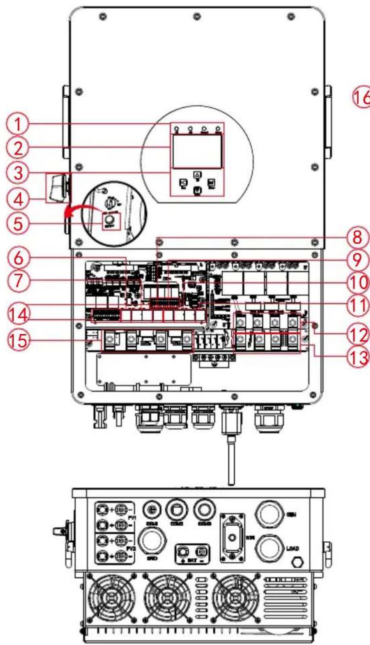
SUN-20/25K-SG01HP3-EU-AM2
1: Inverter indicators
2: LCD display
3: Function buttons
4: DC switch
5: Power on/off button
6: Meter port
7: Parallel port
8: CAN port
9: DRM port
10: BMS port
11: RS485 port
12: Generator input 18: WiFi Interface

SUN-5/6K-SG01HP3-EU-AM2
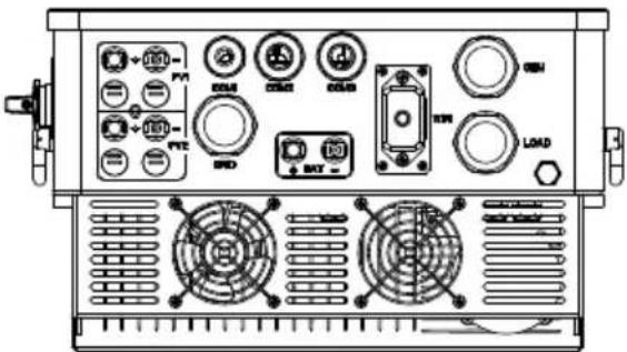
SUN-8/10K-SG01HP3-EU-AM2
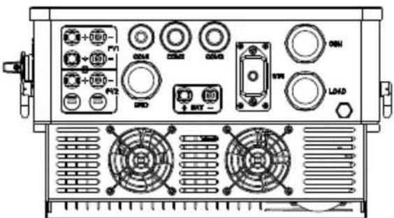
SUN-12/15K-SG01HP3-EU-AM2
13: Load
14: Function port
15: Grid
16: PV input with two MPPT
17: Battery input
2.2 Product Size

Inverter Size

SUN-5/6K-SG01HP3-EU-AM2

SUN-8/10K-SG01HP3-EU-AM2

SUN-12/15K-SG01HP3-EU-AM2

SUN-20/25K-SG01HP3-EU-AM2


2.3 Product Features
- 230V/400V Three phase Pure sine wave inverter.
- Self-consumption and feed-in to the grid.
- Auto restart while AC is recovering.
- Programmable supply priority for battery or grid.
- Programmable multiple operation modes: On grid, off grid and UPS.
- Configurable battery charging current/voltage based on applications by LCD setting.
- Configurable AC/Solar/Generator Charger priority by LCD setting.
- Compatible with mains voltage or generator power.
- Overload/over temperature/short circuit protection.
- Smart battery charger design for optimized battery performance
- With limit function, prevent excess power overflow to the grid.
- Supporting WIFI monitoring and build-in 2 strings for 1 MPP tracker, 1 string for 1 MPP tracker.
- Smart settable three stages MPPT charging for optimized battery performance.
- Time of use function.
- Smart Load Function.
2.4 Basic System Architecture
The following illustration shows basic application of this inverter.
It also includes following devices to have a complete running system.
- Generator or Utility
- PV modules
Consult with your system integrator for other possible system architectures depending on your requirements.
This inverter can power all kinds of appliances in home or office environment, including motor type appliances such as refrigerator and air conditioner.
![graph TD Solar["Solar"] -->|Wireless| GridCell["Grid Cell"] Battery["Battery"] -->|Wireless| GridCell GridCell -->|Wireless| WiFi["Wi-Fi"] GridCell -->|Wireless| GPRS["GPRS"] WiFi --> Cloud["Cloud"] GPRS --> Cloud Cloud --> PhoneCloud["phoneCloud services"] PhoneCloud -->|Wireless| AC_Cable["AC cabl…](/content/2026/05/1064019/images/94fb53a7e51a7713b37da84d246b020e4ece435ad2a4be4b898e137f6ed110a7.jpg)
2.5 Product handling requirements
Two people stand on both sides of the machine, holding one handles to lift the machine.

transport
3. Installation
3.1 Parts List
Check the equipment before installation. Please make sure nothing is damaged in the package. You should have received the items in the following package:

3.2 Mounting instructions
Installation Precaution
This Hybrid inverter is designed for outdoor use(IP65), Please make sure the installation site meets below conditions:
- Not in direct sunlight
· Not in areas where highly flammable materials are stored. - Not in potential explosive areas.
- Not in the cool air directly.
· Not near the television Antenna or antenna cable.
· Not higher than altitude of about 2000 meters above sea level.
· Not in environment of precipitation or humidity(>95%)
Please AVOID direct sunlight, rain exposure, snow laying up during installation and operation. Before connecting all wires, please take off the metal cover by removing screws as shown below:

Considering the following points before selecting where to install:
- Please select a vertical wall with load-bearing capacity for installation, suitable for installation on concrete or other non-flammable surfaces, installation is shown below.
· Install this inverter at eye level in order to allow the LCD display to be read at all times.
· The ambient temperature is recommended to be between -40\~60°C to ensure optimal operation. - Be sure to keep other objects and surfaces as shown in the diagram to guarantee sufficient heat dissipation and have enough space for removing wires.
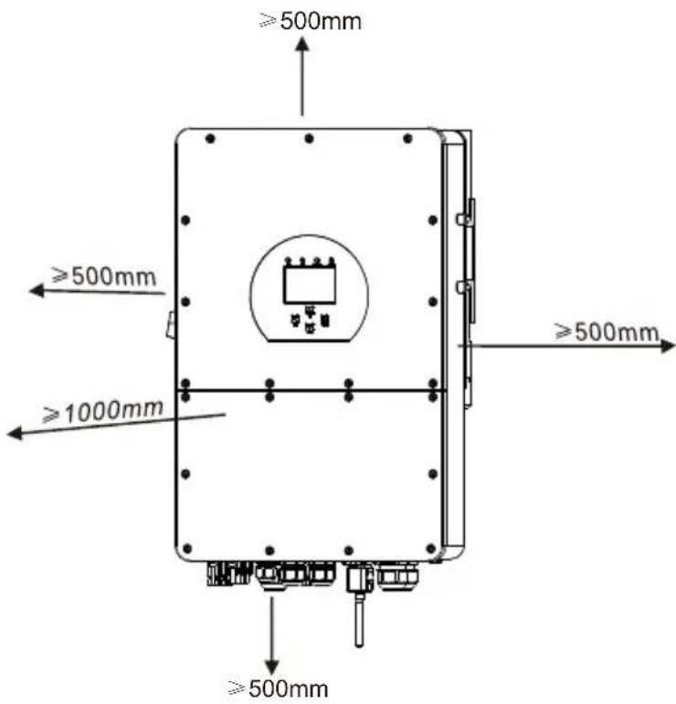
For proper air circulation to dissipate heat, allow a clearance of approx. 50cm to the side and approx. 50cm above and below the unit. And 100cm to the front.
Mounting the inverter
Remember that this inverter is heavy! Please be careful when lifting out from the package. Choose the recommend drill head(as shown in below pic) to drill 4 holes on the wall, 62-70mm deep.
- Use a proper hammer to fit the expansion bolt into the holes.
- Carry the inverter and holding it, make sure the hanger aim at the expansion bolt, fix the inverter on the wall.
- Fasten the screw head of the expansion bolt to finish the mounting.
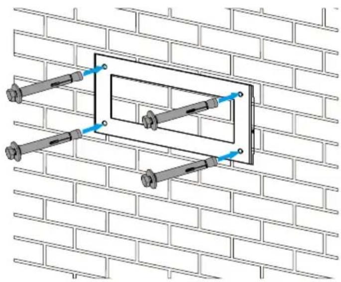
Inverter hanging plate installation

3.3 Battery connection
For safe operation and compliance, a separate DC over-current protector or disconnect device is required between the battery and the inverter. In some applications, switching devices may not be required but over-current protectors are still required. Refer to the typical amperage in the table below for the required fuse or circuit breaker size.

Pic 3.1 DC+ male connector

Pic 3.2 DC- female connector

Safety Hint:
Please use approved DC cable for battery system.
| Model | Cross section (mm2) | |
| Range Recommended value | ||
| 5/6/8/10/12/15/20kW | 4-10(10-6AWG) | 6(8AWG) |
| 25kW | 6-16(10-6AWG) | 10(6AWG) |
Chart 3-2
The steps to assemble the DC connectors are listed as follows: a) Strip off the DC wire about 7mm , disassemble the connector cap nut (see picture 3.3).

Pic 3.3 Disassemble the connector cap nut
b) Crimping metal terminals with crimping pliers as shown in picture 3.4.
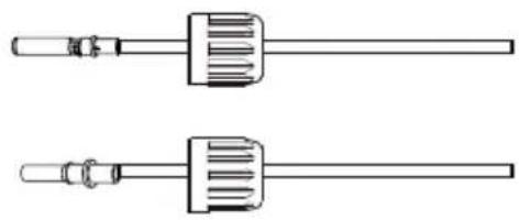
Crimping plier ____

Pic 3.4 Crimp the contact pin to the wire
c) Insert the contact pin to the top part of the connector and screw up the cap nut to the top part of the connector. (as shown in picture 3.5).

Pic 3.5 connector with cap nut screwed on
d) Finally insert the DC connector into the positive and negative input of the inverter, shown as picture 3.6

Pic 3.6 DC input connection
BMS connection


Pass the BMS communication cable through the magnetic ring and wrap it around the magnetic ring four times.
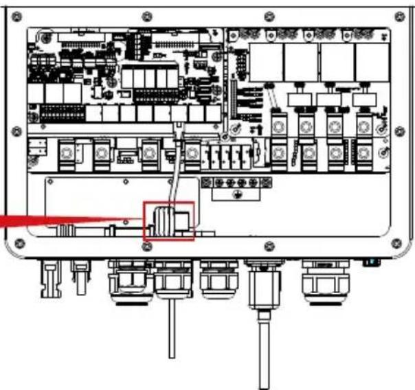
3.3.2 Function port definition


CN1:
CT-R (1,2,7,8): current transformer (CT-R) for "zero export to CT" mode clamps on L1 when in three phase system.
CT-S (3,4,9,10): current transformer (CT-S) for "zero export to CT" mode clamps on L2 when in three phase system.
CT-T (5,6,11,12): current transformer (CT-T) for "zero export to CT" mode clamps on L3 when in three phase system.
CN2:
G-start (1,2): dry contact signal for startup the diesel generator. When the "GEN signal" is active, the open contact (GS) will switch on (no voltage output).
DRY-1 (3,4): Dry contact output. When the inverter is in off-grid mode and the "signal island mode" is checked, the dry contact will switch on.
DRY-2 (5,6): reserved.
RSD+, RSD- (7,8): When battery is connected and the inverter is in "ON" status, it will provide 12Vdc.
SHUT DOWN (9,10,11,12): when the terminal "B" & "B" is short-circuited with additional wire connection, or there's 12Vdc input at the terminal "+ & - ", then the 12Vdc of RSD+ & RSD- will disappear immediately, and the inverter will shutdown immediately.
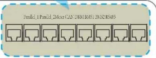
Meter: for energy meter communication.
Parallel_1: Parallel communication port 1.
Parallel_2: Parallel communication port 2.
CAN: reserved.
DRM: Logic interface for AS/NZS 4777.2:2020.
BMS1: BMS port for battery communication port 1.
BMS2: BMS port for battery communication port 2.
RS485: RS485 port.
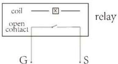
GS (diesel generator startup signal)
3.4 Grid connection and backup load connection
- Before connecting to the grid, a separate AC breaker must be installed between the inverter and the grid, and also between the backup load and the inverter. This will ensure the inverter can be securely disconnected during maintenance and fully protected from over current. For the 5/6/8/10/12/15/20/25kW model, the recommended AC breaker for backup load 5/6/8/10kW is 60A, 12/15/20/25kW is 100A. For the 5/6/8/10/12/15/20/25kW model, the recommended AC breaker for grid 5/6/8/10kW is 60A, 12/15/20/25kW is 100A.
- There are three terminal blocks with "Grid" "Load" and "GEN" markings. Please do not misconnect input and output connectors.

All wiring must be performed by a qualified personnel. It is very important for system safety and efficient operation to use appropriate cable for AC input connection. To reduce risk of injury, please use the proper recommended cable as below.
Grid connection and backup load connection (Copper wires) (bypass)
| Model | Wire Size | Cable( mm2 ) | Torque value(max) |
| 5/6/8/10kW | 8AWG | 6 | 3.4Nm |
| 12/15/20/25kW | 4AWG 16 4.0Nm |
Grid connection and backup load connection (Copper wires)
| Model | Wire Size | Cable( mm2 ) | Torque value(max) |
| 5/6kW | 16AWG | 1.25 | 2.8Nm |
| 8/10/12kW | 12AWG 2.5 2.8Nm | ||
| 15kW 10AWG | 4.0 2.8Nm | ||
| 20kW | 8AWG 6.0 3.4Nm | ||
| 25kW | 6AWG 10 3.4Nm |
Chart 3-3 Recommended Size for AC wires
Please follow below steps to implement Grid, load and Gen port connection:
- Before making Grid, load and Gen port connection, be sure to turn off AC breaker or disconnector first.
- Remove insulation sleeve 10mm length, insert the wires according to polarities indicated on the terminal block. Make sure the connection is complete.


Be sure that AC power source is disconnected before attempting to wire it to the unit.
- Then, insert AC output wires according to polarities indicated on the terminal block and tighten terminal. Be sure to connect corresponding N wires and PE wires to related terminals as well.
- Make sure the wires are securely connected.
- Appliances such as air conditioner are required at least 2-3 minutes to restart because it is required to have enough time to balance refrigerant gas inside of circuit. If a power shortage occurs and recovers in short time, it will cause damage to your connected appliances. To prevent this kind of damage, please check manufacturer of air conditioner if it is equipped with time-delay function before installation. Otherwise, this inverter will trigger overload fault and cut off output to protect your appliance but sometimes it still causes internal damage to the air conditioner
3.5 PV Connection
Before connecting to PV modules, please install a separately DC circuit breaker between inverter and PV modules. It is very important for system safety and efficient operation to use appropriate cable for PV module connection.

To avoid any malfunction, do not connect any PV modules with possible leakage current to the inverter. For example, grounded PV modules will cause leakage current to the inverter. When using PV modules, please ensure the PV+ & PV- of solar panel is not connected to the system ground bar.

It is requested to use PV junction box with surge protection. Otherwise, it will cause damage on inverter when lightning occurs on PV modules.
3.5.1 PV Module Selection:
When selecting proper PV modules, please be sure to consider below parameters:
1) Open circuit Voltage (Voc) of PV modules can not exceed max. PV array open circuit voltage of inverter.
2) Open circuit Voltage (Voc) of PV modules should be higher than min. start voltage.
3) The PV modules used to connected to this inverter shall be Class A rating certified according to IEC 61730.
| Inverter Model | 6kW5kW | 10kW8kW | 12kW 15kW | 20kW | 25kW | ||
| PV Input Voltage | 600V (180V-1000V) | 700V(180V-1000V) | |||||
| PV Array MPPT Voltage Range | 150V-850V | ||||||
| No. of MPP Trackers | 2 | ||||||
| No. of Strings per MPP Tracker | 1+1 | 2+1 | 2+2 | ||||
Chart 3-5
3.5.2 PV Module Wire Connection:
- Switch the Grid Supply Main Switch(AC)OFF.
- Switch the DC Isolator OFF.
- Assemble PV input connector to the inverter.

Safety Hint:
When using PV modules, please ensure the PV+ & PV- of solar panel is not connected to the system ground bar.

Safety Hint:
Before connection, please make sure the polarity of PV array matches the "DC+" and "DC-" symbols.

Safety Hint:
Before connecting inverter, please make sure the PV array open circuit voltage is within the 1000V of the inverter.

Pic 5.1 DC+ male connector

Pic 5.2 DC- female connector

Safety Hint:
Please use approved DC cable for PV system.
| Cable type | Cross section (mm2) | |
| Range Recommended value | ||
| Industry generic PV cable (model: PV1-F) | 2.5-4(12-10AWG) | 4(10AWG) |
Chart 3-6
The steps to assemble the DC connectors are listed as follows:
a) Strip off the DC wire about 7mm, disassemble the connector cap nut (see picture 5.3).

Pic 5.3 Disassemble the connector cap nut
b) Crimping metal terminals with crimping pliers as shown in picture 5.4.

Crimping plier ____
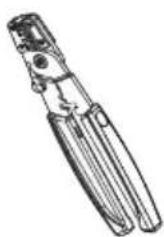
Pic 5.4 Crimp the contact pin to the wire
c) Insert the contact pin to the top part of the connector and screw up the cap nut to the top part of the connector. (as shown in picture 5.5).

Pic 5.5 connector with cap nut screwed on
d) Finally insert the DC connector into the positive and negative input of the inverter, shown as picture 5.6
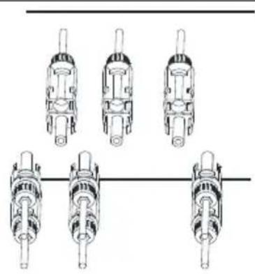
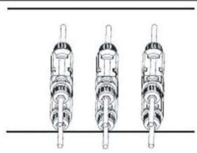
Pic 5.6 DC input connection

Warning:
Sunlight shines on the panel will generate voltage, high voltage in series may cause danger to life. Therefore, before connecting the DC input line, the solar panel needs to be blocked by the opaque material and the DC switch should be 'OFF', otherwise, the high voltage of the inverter may lead to life-threatening conditions. Please do not switch off DC isolator when the DC current when there is high voltage or current. Technicians need to wait until night to keep safety.

Warning:
Please use its own DC power connector from the inverter accessories. Do not interconnect the connectors of different manufacturers.Max. DC input current should be 20A. if exceeds, it may damage the inverter and it is not covered by Deye warranty.
3.6 CT Connection
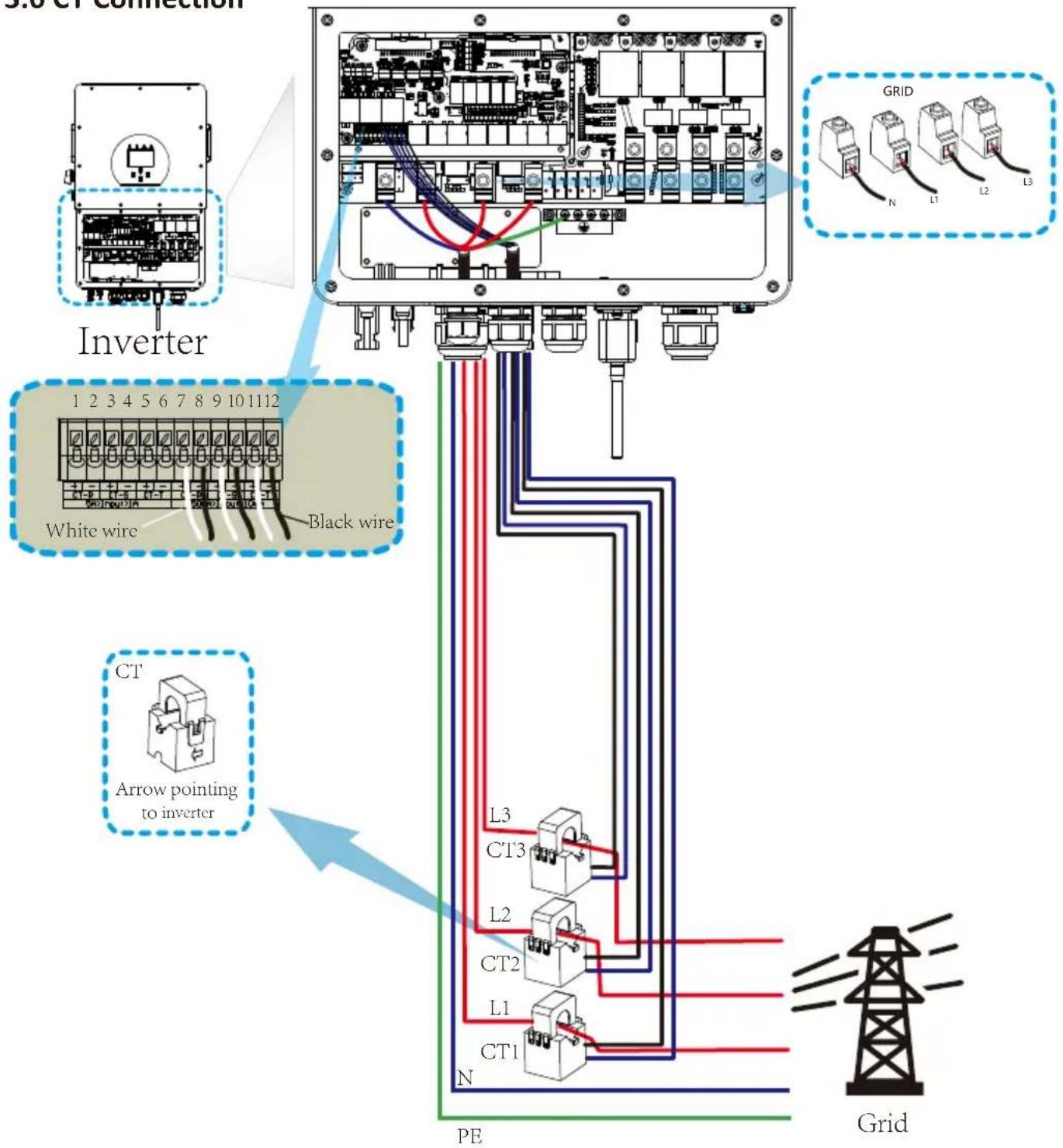
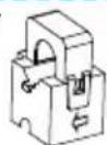
*Note: when the reading of the load power on the LCD is not correct, please reverse the CT arrow.
3.6.1 Meter Connection
![graph TD A["Inverter"] --> B["Grid"] B --> C["RS485A"] B --> D["RS485B"] C --> E["PE"] D --> F["N"] D --> G["L1"] D --> H["L2"] D --> I["L3"] E --> J["Grid"] F --> J G --> J H --> J I --> J K["CHINT DTSU666 CHINT meter"] --> L["Inverter (3,6,9,10)"] L --> M["RS 485 A B"] M --> N["Parallel_Parse_Emit…](/content/2026/05/1064019/images/0acf6d0d3a079387516d66d7a9df7c3add9f6b3fc515186c6410675d27469fa8.jpg)
![graph TD A["Inverter"] --> B["Grid"] B --> C["Parallel_1 Parallel_Emitter"] C --> D["RS485B"] C --> E["RS485A"] C --> F["GND"] D --> G["PE"] D --> H["L1"] D --> I["L2"] D --> J["L3"] D --> K["N"] E --> L["Grid"] E --> M["RS485B R485A GND"] E --> N["Load (5,6,7,8)"] N --> O["Grid"] style A fill:#f9f,…](/content/2026/05/1064019/images/ee3ce745974a849de82a0eeeb48bed89e4cc93658baff559ecebf23a4a102e77.jpg)
![graph TD A["Inverter"] --> B["Home Load"] B --> C["AC Breaker"] C --> D["RS485A"] C --> E["RS485B"] C --> F["PE N L1 L2 L3"] C --> G["Home Line"] G --> H["Grid"] I["CT Current Input"] --> J["Blue line White line"] K["Note: the arrow direction towards the inverter"] --> L["Blue line White line"] M["F…](/content/2026/05/1064019/images/05f0712831ee941691430daabbbe4ad56f27a09a04dab7c3b33554d7cc0c0755.jpg)
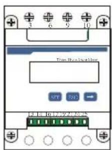
230/400V,3\~
250A/50mA
50/60Hz
CHNT DTSU666
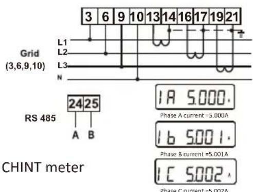
PIN 13,16,19: White cable of the CT
PIN 14,17,21: Blue cable of the CT
![graph TD A["Inverter"] --> B["Home Load"] B --> C["Grid"] D["Parallel 1. Panama 2.5 Meter"] --> E["AC Breaker"] E --> F["RS485A"] E --> G["RS485B"] E --> H["Ground"] I["NA LA L1 L2 L3 N meter"] --> J["AC Breaker"] J --> K["PE N L1 L2 L3"] J --> L["Home Load"] M["CT1"] --> N["PE N L1 L2 L3"] O["CT2"]…](/content/2026/05/1064019/images/24eacc4ffde830b50577b72d1e34f7932d6728d3d77ea6592e507982c3ba458b.jpg)


Note:
When the inverter is in the off-grid state, the N line needs to be connected to the earth.

Note:
In final installation, breaker certified according to IEC 60947-1 and IEC 60947-2 shall be installed with the equipment.
3.7 Earth Connection(mandatory)
Ground cable shall be connected to ground plate on grid side this prevents electric shock if the original protective conductor fails.

Earth Connection (Copper wires) (bypass)
| Model | Wire Size | Cable( mm2 ) | Torque value(max) |
| 5/6/8/10kW | 8AWG | 6 | 3.4Nm |
| 12/15/20/25kW | 4AWG 16 4.0Nm |
Earth Connection (Copper wires)
| Model | Wire Size | Cable( mm2 ) | Torque value(max) |
| 5/6kW | 16AWG | 1.25 | 2.8Nm |
| 8/10/12kW | 12AWG 2.5 2.8Nm | ||
| 15kW 10AWG | 4.0 2.8Nm | ||
| 20kW 8AWG 6 | 0 3.4Nm | ||
| 25kW 6AWG 10 | 3.4Nm |
The conductor should be made of the same metal as the phase conductors.
3.8 WIFI Connection
For the configuration of Wi-Fi Plug, please refer to illustrations of the Wi-Fi Plug. The Wi-Fi Plug is not a standard configuration, it's optional.
3.9 Wiring System for Inverter
![graph TD PV["PV"] --> DC_Breaker["DC Breaker"] DC_Breaker --> Hybrid_Inverter["Hybrid Inverter"] Battery["Battery"] --> DC_Breaker DC_Breaker --> Hybrid_Inverter Hybrid_Inverter --> Load["Load"] Load --> RCD["RCD"] RCD --> Load1["Load"] RCD --> Load2["Load"] RCD --> Load3["Load"] RCD --> Grid["Grid"…](/content/2026/05/1064019/images/6950ca3cddd3d2104669fe2fff84e92be31989276eeadc2a49d07ecc7b955118.jpg)
3.10 Wiring diagram
This diagram is an example for an application in which neutral is separated from the PE in the distribution box. For countries such as China, Germany, the Czech Republic, Italy, etc., please follow local wiring regulations!
![graph TD A["Battery"] --> B["Hybrid Inverter"] C["Solar Array"] --> B B --> D["L1 L1"] B --> E["L2 L2"] B --> F["L3"] B --> G["N"] B --> H["PE or ⊗"] B --> I["Backup"] I --> J["On-Grid"] J --> K["RCD"] K --> L["Distribution box"] L --> M["L3"] L --> N["N"] L --> O["PE"] P["Grid"] --> Q["Home Loads"]…](/content/2026/05/1064019/images/8ad8c1eed6fbb3b4c71fc8cfda457edc07160c6fe0a3f3d10aea466e150270ec.jpg)
![graph TD A["Inverter"] --> B["Battery pack"] B --> C{①DC Breaker} C --> D["Ground"] D --> E{②AC Breaker} E --> F["Home Load"] F --> G["Backup Load"] G --> H["Grid"] H --> I["Home Load"] I --> J["AC Breaker"] J --> K["Ground"] K --> L["Inverter"] style A fill:#f9f,stroke:#333 style G fill:#bbf,stroke…](/content/2026/05/1064019/images/512d71193cd63f74dcf7e76f3e3ccbc001cd1c9a74cc9a39c2d27e4672489077.jpg)
① DC Breaker for battery
SUN 5K-SG-EU: 80A DC breaker
SUN 6K-SG-EU: 80A DC breaker
SUN 8K-SG-EU: 80A DC breaker
SUN 10K-SG-EU: 80A DC breaker
SUN 12K-SG-EU: 80A DC breaker
SUN 15K-SG-EU:80A DC breaker
SUN 20K-SG-EU: 80A DC breaker
SUN 25K-SG-EU: 100A DC breaker
② AC Breaker for backup load
SUN 5K-SG-EU: 60A AC breaker
SUN 6K-SG-EU: 60A AC breaker
SUN 8K-SG-EU: 60A AC breaker
SUN 10K-SG-EU:60A AC breaker
SUN 12K-SG-EU: 100A AC breaker
SUN 15K-SG-EU: 100A AC breaker
SUN 20K-SG-EU: 100A AC breaker
SUN 25K-SG-EU: 100A AC breaker
③ AC Breaker for grid
SUN 5K-SG-EU:60A AC breaker
SUN 6K-SG-EU: 60A AC breaker
SUN 8K-SG-EU: 60A AC breaker
SUN 10K-SG-EU: 60A AC breaker
SUN 12K-SG-EU: 100A AC breaker
SUN 15K-SG-EU: 100A AC breaker
SUN 20K-SG-EU: 100A AC breaker
SUN 25K-SG-EU: 100A AC breaker
④AC Breaker for home load
Depends on household loads
3.11 Typical application diagram of diesel generator
![graph TD A["Generator"] -->|③AC Breaker| B["Ground"] B -->|②AC Breaker| C["Backup Load"] C -->|①DC Breaker for battery| D["Battery pack"] D -->|① DC Breaker for battery| E["GS (diesel generator startup signal)"] E -->|G-start (1,2): dry contact signal for startup the diesel generator.| F["Inverter"]…](/content/2026/05/1064019/images/149975b86f701219d3da96d566429c44872f67648b3f667080434dcf4fa458bd.jpg)
② AC Breaker for backup load
SUN 5K-SG-EU: 60A AC breaker
SUN 6K-SG-EU: 60A AC breaker
SUN 8K-SG-EU: 60A AC breaker
SUN 10K-SG-EU: 60A AC breaker
SUN 12K-SG-EU: 100A AC breaker
SUN 15K-SG-EU: 100A AC breaker
SUN 20K-SG-EU: 100A AC breaker
SUN 25K-SG-EU: 100A AC breaker
③ AC Breaker for Generator port
SUN 5K-SG-EU: 60A AC breaker
SUN 6K-SG-EU: 60A AC breaker
SUN 8K-SG-EU: 60A AC breaker
SUN 10K-SG-EU: 60A AC breaker
SUN 12K-SG-EU: 100A AC breaker
SUN 15K-SG-EU: 100A AC breaker
SUN 20K-SG-EU: 100A AC breaker
SUN 25K-SG-EU: 100A AC breaker
3.12 Three phase parallel connection diagram
Note: For the parallel system, the lead-acid battery is not supported. Please use Deye approved lithium battery.
![graph TD A["Inverter"] -->|①| B["Battery pack"] A -->|②| C["Battery pack"] A -->|③| D["Battery pack"] A -->|④| E["Inverter No.1 (master)"] A -->|⑤| F["Inverter No.2 (slave)"] A -->|⑥| G["Inverter No.3 (slave)"] B --> H["Grid"] C --> I["Ground"] D --> J["Ground"] E --> K["Ground"] F --> L["Ground"] G…](/content/2026/05/1064019/images/9f780886ef706b1bb92dcccb2791509c9c6338a4e49a9f6187da8289ac2e5ead.jpg)
Master inverter Slave Inverter Slave Inverter


Backup Load
4. OPERATION
4.1 Power ON/OFF
Once the unit has been properly installed and the batteries are connected well, simply press On/Off button(located on the left side of the case) to turn on the unit. When system without battery connected, but connect with either PV or grid, and ON/OFF button is switched off, LCD will still light up(Display will show OFF), In this condition, when switch on ON/OFF button and select NO battery, system can still working.
4.2 Operation and Display Panel
The operation and display panel, shown in below chart, is on the front panel of the inverter. It includes four indicators, four function keys and a LCD display, indicating the operating status and input/output power information.
| LED Indicator | Messages | |
| DC | Green led solid light | PV Connection normal |
| AC | Green led solid light | Grid Connection normal |
| Normal | Green led solid light | Inverter operating normal |
| Alarm | Red led solid light | Malfunction or warning |
Chart 4-1 LED indicators
| Function Key | Description |
| Esc | To exit setting mode |
| Up | To go to previous selection |
| Down | To go to next selection |
| Enter | To confirm the selection |
Chart 4-2 Function Buttons
5. LCD Display Icons
5.1 Main Screen
The LCD is touchscreen, below screen shows the overall information of the inverter.

- The icon in the center of the home screen indicates that the system is Normal operation. If it turns into "comm./F01\~F64", it means the inverter has communication errors or other errors, the error message will display under this icon(F01-F64 errors, detail error info can be viewed in the System Alarms menu).
2.At the top of the screen is the time. - System Setup Icon, Press this set button, you can enter into the system setup screen which including Basic Setup, Battery Setup, Grid Setup, System Work Mode, Generator port use, Advanced function and Li-Batt info.
-
The main screen showing the info including Solar, Grid, Load and Battery. Its also displaying the energy flow direction by arrow. When the power is approximate to high level, the color on the panels will changing from green to red so system info showing vividly on the main screen.
-
PV power and Load power always keep positive.
- Grid power negative means sell to grid, positive means get from grid.
- Battery power negative means charge, positive means discharge.
5.1.1 LCD operation flow chart
![graph TD A["Main Screen"] --> B["Solar Page Sc"] A --> C["Grid Page"] A --> D["Inverter Page"] A --> E["Battery Page"] A --> F["Load Page"] A --> G["System Setup"] G --> H["Device info"] G --> I["Advanced Function"] G --> J["Basic Setting"] G --> K["Gen Port Use"] G --> L["Grid Setting"] G --> M["Sy…](/content/2026/05/1064019/images/a441ac2e5bae67d2a4539d477da699857bc83fabc5391cbd9746a01824a15268.jpg)
5.2 Solar Power Curve

This is Solar Panel detail page.
① Solar Panel Generation.
② Voltage, Current, Power for each MPPT.
③ Daily and total PV production.
Press the "Energy" button will enter into the power curve page.

This is Inverter detail page.
① Inverter Generation.
Voltage, Current, Power for each Phase.
AC-T: mean Heat-sink temperature.
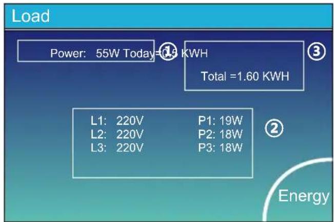
This is Load detail page.
① Load Power.
② Voltage, Power for each Phase.
③ Daily and total Load consumption.
When you check "Selling First" or "Zero export to Load" on system work mode page, the information on this page is about backup load which connect on Load port of hybrid inverter.
When you check "Zero export to CT" on system work mode page, the information on this page is including backup load and home load.
Press the "Energy" button will enter into the power curve page.
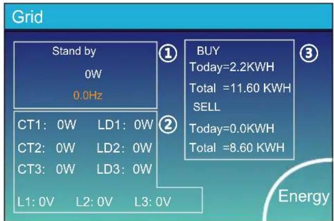
This is Grid detail page.
① Status, Power, Frequency.
② L: Voltage for each Phase
CT: Power detected by the external current sensors
LD: Power detected using internal sensors on AC grid in/out breaker
③ BUY: Energy from Grid to Inverter,
SELL: Energy from Inverter to grid.
Press the "Energy" button will enter into the power curve page.

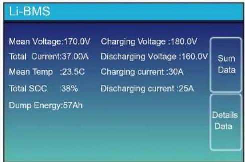
This is Battery detail page.
if you use Lithium Battery, you can enter BMS page.

5.3 Curve Page-Solar & Load & Grid


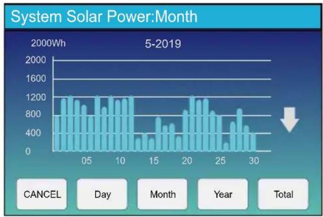

Solar power curve for daily, monthly, yearly and total can be roughly checked on the LCD, for more accuracy power generation, pls check on the monitoring system. Click the up and down arrow to check power curve of different period.
5.4 System Setup Menu
![graph TD A["Battery Setting"] --> B["System Work Mode"] C["Basic Setting"] --> D["Grid Setting"] E["Advanced Function"] --> F["Gen Port Use"] G["Device Info."] --> H["Device Info."]](/content/2026/05/1064019/images/95316626b8471276e1afba49cd58bbb7a10e76ded0622b407c79b327c4c536b2.jpg)
This is System Setup page.
5.5 Basic Setup Menu
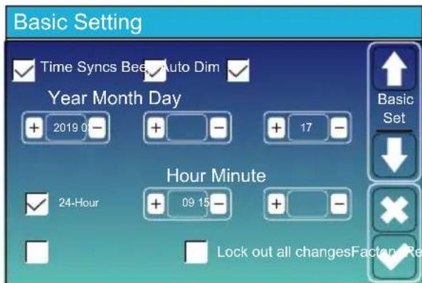
Factory Reset: Reset all parameters of the inverter. Lock out all changes: Enable this menu for setting parameters that require locking and cannot be set up. Before performing a successful factory reset and locking the systems, to keep all changes you need to type in a password to enable the setting. The password for factory settings is 9999 and for lock out is 7777.

Factory Reset Password: 9999 Lock out all changes Password: 7777
5.6 Battery Setup Menu
Battery Setting

Battery capacity: it shows your battery bank size to Deye hybrid inverter.
Use Batt V: Use Battery Voltage for all the settings (V).
Max. A charge/discharge: Max battery charge/discharge current(0-30A for 5/6kW model, 0-37A for 8/10/12/15/20kW model, 0-50A for 25kW model).
For AGM and Flooded, we recommend Ah battery size x 20%= Charge/Discharge amps.
. For Lithium, we recommend Ah battery size x 50% = Charge/Discharge amps.
. For Gel, follow manufacturer's instructions.
No Batt: tick this item if no battery is connected to the system.
Parallel bat1&bat2: if one set of battery was connected Bat 1 and Bat 2 then please enable this function.
Battery Setting

This is Battery Setup page.

Start =30%: Percent SOC below 30% system will AutoStart a connected generator to charge the battery bank.
A = 20A: Charge rate of 20A from the attached generator in Amps.
Gen Charge: uses the gen input of the system to charge battery bank from an attached generator.
Gen Signal: Normally open relay that closes when the Gen Start signal state is active.
This is Grid Charge, you need select. ②
Start =30%: No use, Just for customization.
A = 37A: It indicates the Current that the Grid charges the Battery.
Grid Charge: It indicates that the grid charges the battery.
Grid Signal: Disable.
Gen Max Run Time: It indicates the longest time Generator can run in one day, when time is up, the Generator will be turned off. 24H means that it does not shut down all the time.
Gen Down Time: It indicates the delay time of the Generator to shut down after it has reached the running time.

This page tells the PV and diesel generator power the load and battery.
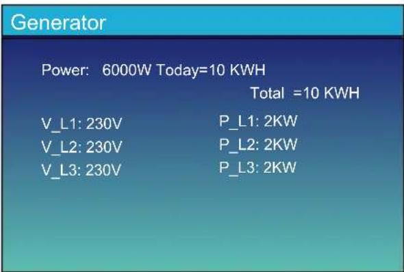


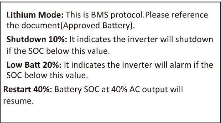
Recommended battery settings
| Battery Type Absorption Stage Float Stage | Torque value (every 30 days 3hr) | ||
| Lithium Follow its BMS voltage parameters | |||
5.7 System Work Mode Setup Menu

Work Mode
Selling First: This Mode allows hybrid inverter to sell back any excess power produced by the solar panels to the grid. If time of use is active, the battery energy also can be sold into grid.
The PV energy will be used to power the load and charge the battery and then excess energy will flow to grid. Power source priority for the load is as follows:
- Solar Panels.
- Grid.
- Batteries (until programable % discharge is reached).
Zero Export To Load: Hybrid inverter will only provide power to the backup load connected. The hybrid inverter will neither provide power to the home load nor sell power to grid. The built-in CT will detect power flowing back to the grid and will reduce the power of the inverter only to supply the local load and charge the battery.
![graph LR A["Solar"] --> B["Battery"] B --> C["Computer"] C --> D["House"] D --> E["GridBack"]](/content/2026/05/1064019/images/bccf01e314e13f4491264480c104364161f3eb74e368349622c4fed52c0e556f.jpg)
GridBackup Load On-Grid Home Load
Zero Export To CT: Hybrid inverter will not only provide power to the backup load connected but also give power to the home load connected. If PV power and battery power is insufficient, it will take grid energy as supplement. The hybrid inverter will not sell power to grid. In this mode, a CT is needed. The installation method of the CT please refer to chapter 3.6 CT Connection. The external CT will detect power flowing back to the grid and will reduce the power of the inverter only to supply the local load, charge battery and home load.
![graph LR A["Solar"] --> B["Battery"] B --> C["Computer"] C --> D["Home"] D --> E["GridBack"] E --> F["CT"]](/content/2026/05/1064019/images/4bee9597f9f6d2751c6c754b6e569d05bd64a5cefb0f829745b8b0110d7c4530.jpg)
GridBackup Load On-Grid Home Load
Solar Sell: "Solar sell" is for Zero export to load or Zero export to CT: when this item is active, the surplus energy can be sold back to grid. When it is active, PV Power source priority usage is as follows: load consumption and charge battery and feed into grid.
Max. sell power: Allowed the maximum output power to flow to grid.
Zero-export Power: for zero-export mode, it tells the grid output power. Recommend to set it as 20-100W to ensure the hybrid inverter won't feed power to grid.
Energy Pattern: PV Power source priority.
Batt First: PV power is firstly used to charge the battery and then used to power the load. If PV power is insufficient, grid will make supplement for battery and load simultaneously.
Load First: PV power is firstly used to power the load and then used to charge the battery. If PV power is insufficient, Grid will provide power to load.
Max Solar Power: allowed the maximum DC input power.
Grid Peak-shaving: when it is active, grid output power will be limited within the set value. If the load power exceeds the allowed value, it will take PV energy and battery as supplement. If still can't meet the load requirement, grid power will increase to meet the load needs.
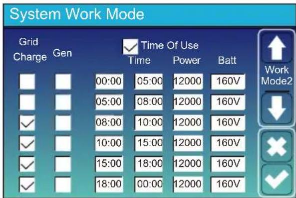
Battery Setting

System Work Mode
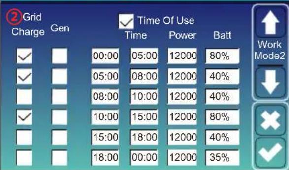
Time of use: it is used to program when to use grid or generator to charge the battery, and when to discharge the battery to power the load. Only tick "Time Of Use" then the follow items (Grid, charge, time, power etc.) will take effect.
Note: when in selling first mode and click time of use, the battery power can be sold into grid.
Gen charge: utilize diesel generator to charge the battery in a time period.
Time: real time, range of 01:00-24:00.
Note: when the grid is present, only the "time of use" is ticked, then the battery will discharge. Otherwise, the battery won't discharge even the battery SOC is full. But in the off-grid mode (when grid is not available, inverter will work in the off-grid mode automatically), the battery will discharge without selecting the "Time Of Use".
Power: Max. discharge power of battery allowed.
Batt(V or SOC %): battery SOC % or voltage at when the action is to happen.
For example
During 00:00-05:00,
if battery SOC is lower than 80%, it will use grid to charge the battery until battery SOC reaches 80%.
During 05:00-08:00,
if battery SOC is higher than 40%, hybrid inverter will discharge the battery until the SOC reaches 40%. At the same time, if battery SOC is lower than 40%, then grid will charge the battery SOC to 40%.
During 08:00-10:00,
if battery SOC is higher than 40%, hybrid inverter will discharge the battery until the SOC reaches 40%.
During 10:00-15:00,
when battery SOC is higher than 80%, hybrid inverter will discharge the battery until the SOC reaches 80%.
During 15:00-18:00,
when battery SOC is higher than 40%, hybrid inverter will discharge the battery until the SOC reaches 40%.
During 18:00-00:00,
when battery SOC is higher than 35%, hybrid inverter will discharge the battery until the SOC reaches 35%.
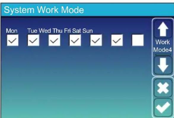
It allows users to choose which day to execute the setting of "Time of Use".
For example, the inverter will execute the time of use page on Mon/Tue/Wed/Thu/Fri/Sat only.
5.8 Grid Setup Menu

Grid Mode:
General Standard、UL1741 & IEEE1547、CPUC RULE21、SRD-UL-1741、CEI_0_21_Internal、EN50549_CZ-PPDS(>16A)、Australia_A、Australia_B、Australia_C、AS4777_NewZealand、VDE4105、OVE-Directive R25、EN50549_CZ_PPDS_L16A、NRS097、G98、G99、EN50549_1_Norway_133V、EN50549_1_Norway_230V、Japan_200VAC_3P3W、CEI_0_21_External、CEI_0_21_Areti、Japan_400VAC_3P3W、Japan_415VAC_3P4W、EN50549_1_Switzerland. Please follow the local grid code and then choose the corresponding grid standard.
Grid level: there're several voltage levels for the inverter output voltage when it is in off-grid mode. LN:220V/LL:380V(AC), LN:230V/LL:400V(AC).
IT system: If the grid system is IT system, then please enable this option. For example, the IT grid system voltage is 230Vac (the Line voltage between any two live lines in a three-phase circuit is 230Vac, and the diagram is as follow) then please enable "IT system" and tick the "Grid level" as LN:230V/LL:400V(AC) as below picture shows.

Rz: Large resistance ground resistor. Or the system doesn't have Neutral line
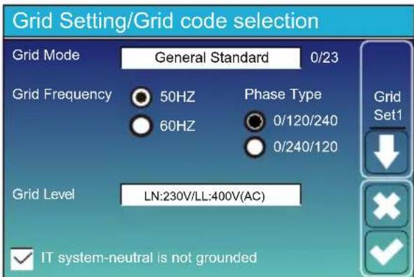
Grid Setting/Connect

Normal connect: The allowed grid voltage/frequency range when the inverter first time connect to the grid. Normal Ramp rate: It is the startup power ramp.
Reconnect after trip: The allowed grid voltage /frequency range for the inverter connects the grid after the inverter trip from the grid. Reconnect Ramp rate: It is the reconnection power ramp
Reconnection time: The waiting time period for the inverter connects the grid again. PF: Power factor which is used to adjust inverter reactive power.
Grid Setting/IP Protection

HV1: Level 1 overvoltage protection point;
① HV2: Level 2 overvoltage protection point; ② 0.10s—Trip time.
HV3: Level 3 overvoltage protection point.
LV1: Level 1 undervoltage protection point;
LV2: Level 2 undervoltage protection point;
LV3: Level 3 undervoltage protection point.
HF1: Level 1 over frequency protection point;
HF2: Level 2 over frequency protection point;
HF3: Level 3 over frequency protection point.
LF1: Level 1 under frequency protection point;
LF2: Level 2 under frequency protection point;
LF3: Level 3 under frequency protection point.

FW: this series inverter is able to adjust inverter output power according to grid frequency.
Droop F: percentage of nominal power per Hz For example, "Start freq F > 50.2Hz, Stop freq F < 51.5, Droop F = 40%PE/Hz" when the grid frequency reaches 50.2Hz, the inverter will decrease its active power at Droop F of 40%. And then when grid system frequency is less than 50.1Hz, the inverter will stop decreasing output power. For the detailed setup values, please follow the local grid code.

V(W): It is used to adjust the inverter active power according to the set grid voltage.
V(Q): It is used to adjust the inverter reactive power according to the set grid voltage. This function is used to adjust inverter output power (active power and reactive power) when grid voltage changes.
Lock-in/Pn 5%: When the inverter active power is less than 5% rated power, the VQ mode will not take effect. Lock-out/Pn 20%: If the inverter active power is increasing from 5% to 20% rated power, the VQ mode will take effect again.
For example: V2=110%, P2=80%. When the grid voltage reaches the 110% times of rated grid voltage, inverter output power will reduce its active output power to 80% rated power. For example: V1=94%, Q1=44%. When the grid voltage reaches the 94% times of rated grid voltage, inverter output power will output 44% reactive output power. For the detailed setup values, please follow the local grid code.
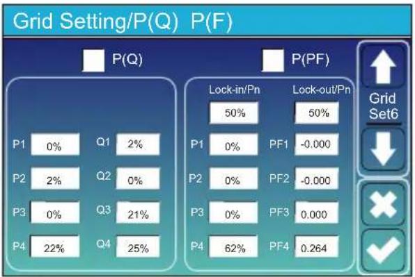
P(Q): It is used to adjust the inverter reactive power according to the set active power. P(PF): It is used to adjust the inverter PF according to the set active power. For the detailed setup values, please follow the local grid code. Lock-in/Pn 50%: When the inverter output active power is less then 50% rated power, it won't enter the P(PF) mode. Lock-out/Pn 50%: When the inverter output active power is higher then 50% rated power, it will enter the P(PF) mode. Note : only when the grid voltage is equal to or higher than 1.05 times of rated grid voltage, then the P(PF) mode will take effect.

Reserved: This function is reserved. It is not recommended.
5.9 Generator Port Use Setup Menu

Generator input rated power: allowed Max. power from diesel generator.
GEN connect to grid input: connect the diesel generator to the grid input port.
Smart Load Output: This mode utilizes the Gen input connection as an output which only receives power when the battery SOC is above a user programmable threshold.
e.g. ON: 100%, OFF: 95%: When the battery bank SOC reaches 100%, Smart Load Port will switch on automatically and power the load connected. When the battery bank SOC < 95%, the Smart Load Port will switch off automatically.
Smart Load OFF Batt
- Battery SOC at which the Smart load will switch off.
Smart Load ON Batt
- Battery SOC at which the Smart load will switch on. simultaneously and then the Smart load will switch on.
On Grid always on: When click "on Grid always on" the smart load will switch on when the grid is present.
Micro Inv Input: To use the Generator input port as a micro-inverter on grid inverter input (AC coupled), this feature will also work with "Grid-Tied" inverters.
* Micro Inv Input OFF: when the battery SOC exceeds setting value, Microinveter or grid-tied inverter will shut down.
* Micro Inv Input ON: when the battery SOC is lower than setting value, Microinveter or grid-tied inverter will start to work.
AC Couple Frz High: If choosing "Micro Inv input", as the battery SOC reaches gradually setting value (OFF), during the process, the microinverter output power will decrease linear. When the battery SOC equals to the setting value (OFF), the system frequency will become the setting value (AC couple Frz high) and the Microinverter will stop working.
MI export to grid cutsoff: Stop exporting power produced by the microinverter to the grid.
* Note: Micro Inv Input OFF and On is valid for some certain FW version only.
5.10 Advanced Function Setup Menu
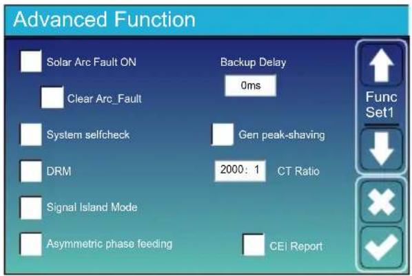
Solar Arc Fault ON: This is only for US.
System selfcheck: Disable. this is only for factory.
Gen Peak-shaving: Enable When the power of the generator exceeds the rated value of it, the inverter will provide the redundant part to ensure that the generator will not overload.
DRM: For AS4777 standard.
Backup Delay: When the grid cuts off, the inverter will give output power after the setting time.
For example, backup delay: 3ms. the inverter will give output power after 3ms when the grid cuts off.
Note: for some old FW version, the function is not available.
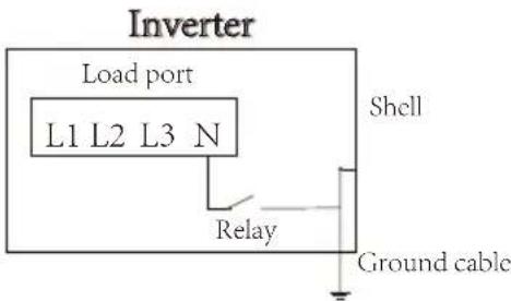
Signal island mode: If "Signal island mode" is checked and When inverter is in off-grid mode, the relay on the Neutral line (load port N line) will switch ON then the N line (load port N line) will bind to inverter ground.
Asymmetric phase feeding: If it was checked, the inverter will take power from the grid balance of on each phase (L1/L2/L3) when needed.
Advanced Function

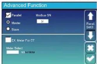
Ex_Meter For CT: when using zero-export to CT mode, the hybrid inverter can select EX_Meter For CT function and use the different meters.e.g.CHNT and Eastron.
5.11 Device Info Setup Menu
Device Info.

This page show Inverter ID, Inverter version and alarm codes.
HMI: LCD version
MAIN: Control board FW version
6. Mode
Mode I:Basic
![graph TD A["Solar"] --> B["Battery"] B --> C["Grid"] D["AC cable DC cable"] --> E["Backup Load On-Grid Home Load"] F["COM cable"] --> E E --> G["CT"] G --> H["Grid"]](/content/2026/05/1064019/images/aead69881978f21fdcead9b7149816d903406016e907c859c06b2ef20337c2c8.jpg)
Mode II: With Generator
![graph TD Solar["Solar"] -->|AC cable| Generator["Generator"] Battery["Battery"] -->|AC cable| Generator Battery -->|DC cable| Grid["Grid"] Battery --> BackupLoad["Backup Load"] BackupLoad --> OnGridHome["On-Grid Home Load"] OnGridHome --> Grid Grid --> CT["CT"] AC_Cable["AC cable"] --> Grid DC_Cable…](/content/2026/05/1064019/images/1c69364f33938587596fe0323cec7f86162a3667a54485b6181fef60d381cde0.jpg)
Mode III: With Smart-Load
![graph TD A["Solar"] --> B["DC Cable"] C["Battery"] --> B B --> D["Backup Load On-Grid Home Load"] D --> E["CT"] E --> F["Grid"] F --> G["Smart Load"] G --> H["Grid"] style A fill:#f9f,stroke:#333 style C fill:#f9f,stroke:#333 style B fill:#ccf,stroke:#333 style D fill:#cfc,stroke:#333 style E fill:#…](/content/2026/05/1064019/images/4dc14f0249c2d67f3e73da2d5237334abceabf99da352bda7649a5eea1a8ac97.jpg)
Mode IV: AC Couple
![graph TD A["Solar"] --> B["On-Grid + AC couple"] C["Battery"] --> B B --> D["Backup Load On-Grid Home Load"] D --> E["On-Grid Inverter"] E --> F["CT"] F --> G["Grid"] H["AC cable DC cable"] --> D](/content/2026/05/1064019/images/bae63c046b789cdd302fe49e16bd2109f723f71a1fab7ee7a889cba190965997.jpg)

The 1st priority power of the system is always the PV power, then 2nd and 3rd priority power will be the battery bank or grid according to the settings. The last power backup will be the Generator if it is available.
7. Limitation of Liability
In addition to the product warranty described alone, the state and local laws and regulations provide financial compensation for the product's power connection (including violation of implied terms and warranties). The company hereby declares that the terms and conditions of the product and the policy can and can only legally exclude all liability within a limited scope.
| Error code | Description Solutions | |
| F01 DC_Inversed_Failure | 1, Check the PV input polarity2, Seek help from us, if can not go back to normal state. | |
| F07 | DC_START_Failure | 1, The BUS voltage can't be built from PV or battery.2, Restart the inverter, If the fault still exists, please contact us for help |
| F13 | Working_Mode_change | When the grid type and frequency changed it will report F13;When the battery mode was changed to “No battery” mode, it will report F13;For some old FW version, it will report F13 when the system work mode changed;Generally, it will disappear automatically when shows F13;If it remains same, turn on DC and AC switch for one minute, then turn on the DC and AC switch.;Seek help from us, if can not go back to normal state. |
| F15 | AC_OverCurr_SW_Failure | AC side over current faultPlease check whether the backup load power and common load power are within the range;Restart and check whether it is normal;Seek help from us, if can not go back to normal state. |
| F16 GFCI_Failure | Leakage current faultCheck the PV side cable ground connectionRestart the system 2-3 timesif the fault still existing, please contact us for help. | |
| F18 | Tz_Ac_OverCurr_Fault | AC side over current faultPlease check whether the backup load power and commonplace power are within the range;Restart and check whether it is normal;Seek help from us, if cannot go back to normal state. |
| F20 | Tz_Dc_OverCurr_Fault | DC side over current faultCheck PV module connection and battery connection;When in the off-grid mode, the inverter startup with big power load, it may report F20. Please reduce the load power connected;If it remains same, turn on DC and AC switch for one minute, then turn on the DC and AC switch.;Seek help from us, if can not go back to normal state. |
| F21 Tz_HV_Overcurr_fault | BUS over current.1, Check the PV input current and battery current setting2. Restart the system 2~3 times.3. If the fault still exists, please contact us for help. | |
| F22 | Tz_EmergStop_Fault | Remotely shutdown1, it tells the inverter is remotely controlled. |
| F23 | Tz_GFCI_OC_Fault | Leakage current fault1. Check PV side cable ground connection.2. Restart the system 2~3 times.3. If the fault still exists, please contact us for help. |
| F24 DC Insulation_Fault | PV isolation resistance is too low1. Check the connection of PV panels and inverter is firmly and correctly;2. Check whether the PE cable of inverter is connected to ground;3. Seek help from us, if can not go back to normal state. | |
| F26 Bus Unbalance_Fault | 1. Please wait for a while and check whether it is normal;2. When the load power of 3 phases is big different, it will report the F26.3. When there's DC leakage current, it will report F264. Restart the system 2~3 times.5. Seek help from us, if can not go back to normal state. | |
| F29 | Parallel_Comm_Fault | 1. When in parallel mode, check the parallel communication cable connection and hybrid inverter communication address setting;2. During the parallel system startup period, inverters will report F29. But when all inverters are in ON status, it will disappear automatically;3. If the fault still exists, please contact us for help. |
| F34 AC Overload_Fault | 1, Check the backup load connection, make sure it is in allowed power range2, If the fault still exists, please contact us for help | |
| F41 Parallel_system_Stop | 1, Check the hybrid inverter work status. If there's 1pcs hybrid inverter shutdown, all hybrid inverters will report F41 fault.2, If the fault still exists, please contact us for help | |
| F42 | Parallel_Version_Fault | 1. Check whether the inverter version is consistent.2. Please contact us to upgrade the software version. |
| F47 | AC_OverFreq_Fault | Grid frequency out of range1. Check the frequency is in the range of specification or not;2. Check whether AC cables are firmly and correctly connected;3. Seek help from us, if can not go back to normal state. |
| F48 | AC_UnderFreq_Fault | Grid frequency out of range1. Check the frequency is in the range of specification or not;2. Check whether AC cables are firmly and correctly connected;3. Seek help from us, if can not go back to normal state. |
| F52 DC_VoltHigh_Fault | BUS voltage is too high1. Check whether battery voltage is too high;2. check the PV input voltage, make sure it is within the allowed range;3. Seek help from us, if can not go back to normal state. | |
| F53 DC_VoltLow_Fault | BUS voltage is too low1. Check whether battery voltage is too low;2. If the battery voltage is too low, using PV or grid to charge the battery;3. Seek help from us, if can not go back to normal state. | |
| F54 BAT2_VoltHigh_Fault | 1. Check the battery 2 terminal voltage is high;2. Restart the inverter 2 times and restore the factory settings;3. Seek help from us, if can not go back to normal state. | |
| F55 BAT1_VoltHigh_Fault | 1. Check the battery 1 terminal voltage is high;2. Restart the inverter 2 times and restore the factory settings;3. Seek help from us, if can not go back to normal state. | |
| F56 BAT1_VoltLow_Fault | 1. Check the battery 1 terminal voltage is low;2. Restart the inverter 2 times and restore the factory settings;3. Seek help from us, if can not go back to normal state. | |
| F57 BAT2_VoltLow_Fault | 1. Check the battery 2 terminal voltage is low;2. Restart the inverter 2 times and restore the factory settings;3. Seek help from us, if can not go back to normal state. | |
| F58 Battery_comm Lose | 1, It tells the communication between hybrid inverter and battery BMS disconnected when “BMS_Err-Stop” is active;2, If don’t want to see this happen, you can disable “BMS_Err-Stop” item on the LCD;3, If the fault still exists, please contact us for help | |
| F62 DRMs0_stop | 1, the DRM function is for Australia market only;2, Check the DRM function is active or not;3, Seek help from us, if can not go back to normal state after restart the system. | |
| F63 ARC_Fault | 1. ARC fault detection is only for US market;2. Check PV module cable connection and clear the fault;3. Seek help from us, if can not go back to normal state | |
| F64 | Heatsink_HighTemp_Fault | Heat sink temperature is too high1. Check whether the working environment temperature is too high;2. Turn off the inverter for 10mins and restart;3. Seek help from us, if can not go back to normal state. |
Chart 7-1 Fault information
Under the guidance of our company, customers return our products so that our company can provide service of maintenance or replacement of products of the same value. Customers need to pay the necessary freight and other related costs. Any replacement or repair of the product will cover the remaining warranty period of the product. If any part of the product or product is replaced by the company itself during the warranty period, all rights and interests of the replacement product or component belong to the company.
Factory warranty does not include damage due to the following reasons:
- Damage during transportation of equipment;
· Damage caused by incorrect installation or commissioning; - Damage caused by failure to comply with operation instructions, installation instructions or maintenance instructions;
- Damage caused by attempts to modify, alter or repair products;
- Damage caused by incorrect use or operation;
- Damage caused by insufficient ventilation of equipment;
· Damage caused by failure to comply with applicable safety standards or regulations; - Damage caused by natural disasters or force majeure (e.g. floods, lightning, overvoltage, storms, fires, etc.)
In addition, normal wear or any other failure will not affect the basic operation of the product. Any external scratches, stains or natural mechanical wear does not represent a defect in the product.
- Datasheet
| Model | SUN-5K-SG01HP3-EU-AM2 | SUN-6K-SG01HP3-EU-AM2 | SUN-8K-SG01HP3-EU-AM2 | SUN-10K-SG01HP3-EU-AM2 |
| Battery Input Data | ||||
| Battery Type | Lithium-ion | |||
| Battery Voltage Range(V) | 160-700 | |||
| Max. Charging Current(A) | 30 | 37 | ||
| Max. Discharging Current(A) | 30 | 37 | ||
| Charging Strategy for Li-ion Battery | Self-adaption to BMS | |||
| Number of Battery Input 1 | ||||
| PV String Input Data | ||||
| Max. PV Input Power(W) | 6500 | 7800 | 10400 | 13000 |
| Max. PV Input Voltage (V) | 1000 | |||
| Start-up Voltage(V) | 180 | |||
| MPPT Voltage Range(V) | 150-850 | |||
| Full Load MPPT Voltage Range(V) | 195-850 | 195-850 | 260-850 | 325-850 |
| Rated PV Input Voltage (V) | 600 | |||
| Max. Operating PV Input Current(A) | 20+20 | 20+20 | 20+20 | 20+20 |
| Max. Input Short-Circuit Current(A) | 30+30 | 30+30 | 30+30 | 30+30 |
| No. of MPP Trackers/No. of Strings per MPP Tracker | 2/1+1 | |||
| Max. Inverter Backfeed Current To the Array | 0 | |||
| AC Input/Output Data | ||||
| Rated AC Input/Output Active Power(W) | 5000 | 6000 | 8000 | 10000 |
| Max. AC Input/Output Apparent Power(VA) | 5500 | 6600 | 8800 | 11000 |
| Peak Power (off-grid)(W) | 1.5 time of rated power, 10 S | |||
| Rated AC Input/Output Current(A) | 7.6/7.3 | 9.1/8.7 | 12.2/11.6 | 15.2/14.5 |
| Max. AC Input/Output Current(A) | 8.4/8.0 | 10/9.6 | 13.4/12.8 | 16.7/16 |
| Max. Three-phase Unbalanced Output Current(A) | 13 | 13 | 18 | 22 |
| Max. Continuous AC Passthrough (grid to load)(A) | 40 | |||
| Rated Input/Output Voltage/Range(V) | 220/380V, 230/400V 0.85Un-1.1Un | |||
| Grid Connection Form | 3L+N+PE | |||
| Rated Input/Output Grid Frequency/Range | 50Hz/45Hz-55Hz 60Hz/55Hz-65Hz | |||
| Power Factor Adjustment Range | 0.8 leading to 0.8 lagging | |||
| Total Current Harmonic Distortion THDi | <3% (of nominal power) | |||
| <0.5% InDC Injection Current | ||||
| Efficiency | ||||
| Max. Efficiency | 97.60% | |||
| 97.00%Euro Efficiency | ||||
| MPPT Efficiency | >99% | |||
| Equipment Protection | ||||
| DC Polarity Reverse Connection Protection | Yes | |||
| AC Output Overcurrent Protection | Yes | |||
| YesAC Output Overvoltage Protection | ||||
| YesAC Output Short Circuit Protection | ||||
| Thermal Protection Yes | ||||
| DC Terminal Insulation Impedance Monitoring | Yes | |||
| YesDC Component Monitoring | ||||
| YesGround Fault Current Monitoring | ||||
| Power Network Monitoring | Yes | |||
| Island Protection Monitoring | Yes | |||
| Earth Fault Detection | Yes | |||
| DC Input Switch | Yes | |||
| Overvoltage Load Drop Protection | Yes | |||
| Residual Current (RCD) Detection | Yes | |||
| Surge Protection Level | TYPE II(DC), TYPE II(AC) | |||
| Interface | ||||
| LCD/LED display | LCD | |||
| Communication Interface WIFI,RS485, CAN | ||||
| General Data | ||||
| Operating Temperature Range | -40 to +60°C, >45°C Derating | |||
| Permissible Ambient Humidity | 0-100% | |||
| Permissible Altitude | 2000m | |||
| Noise | ≤ 55 dB | |||
| Ingress Protection(IP) Rating | IP 65 | |||
| Inverter Topology | Non-Isolated | |||
| Over Voltage Category | OVC II(DC), OVC III(AC) | |||
| Cabinet size(W*H*D) [mm] | 408W×638H×237D (Excluding connectors and brackets) | |||
| Weight(kg) | 30.5 | |||
| Installation Style Wall-mounted | ||||
| Warranty | 5 Years/10 Yearsthe Warranty Period Depends the Final Installation Site of Inverter,More Info Please Refer to Warranty Policy | |||
| Type of Cooling | Intelligent Air CoolingNatur | |||
| Grid Regulation | IEC 61727,IEC 62116,CEI 0-21,EN 50549,NRS 097,RD 140,UNE 217002,OVE-Richtlinie R25,G99,VDE-AR-N 4105 | |||
| Safety EMC/Standard | IEC/EN 61000-6-1/2/3/4, IEC/EN 62109-1, IEC/EN 62109-2 | |||
| Model | SUN-12K-SG01HP3-EU-AM2 | SUN-15K-SG01HP3-EU-AM2 | SUN-20K-SG01HP3-EU-AM2 | SUN-25K-SG01HP3-EU-AM2 |
| Battery Input Data | ||||
| Battery Type | Lithium-ion | |||
| Battery Voltage Range(V) | 160-700 | |||
| Max. Charging Current(A) | 37 | 50 | ||
| Max. Discharging Current(A) | 37 | 50 | ||
| Charging Strategy for Li-ion Battery | Self-adaption to BMS | |||
| Number of Battery Input 1 | ||||
| PV String Input Data | ||||
| Max. PV Input Power(W) | 15600 | 19500 | 26000 | 32500 |
| Max. PV Input Voltage (V) | 1000 | |||
| Start-up Voltage(V) | 180 | |||
| MPPT Voltage Range(V) | 150-850 | |||
| Full Load MPPT Voltage Range(V) | 340-850 | 420-850 | 500-850 | 625-850 |
| Rated PV Input Voltage (V) | 600 700 | |||
| Max. Operating PV Input Current(A) | 26+20 | 26+20 | 26+26 | 26+26 |
| Max. Input Short-Circuit Current(A) | 39+30 | 39+30 | 39+39 | 39+39 |
| No. of MPP Trackers/No. of Strings per MPP Tracker | 2/2+22/2+1 | |||
| Max. Inverter Backfeed Current To the Array | 0 | |||
| AC Input/Output Data | ||||
| Rated AC Input/Output Active Power(W) | 12000 | 15000 | 20000 | 25000 |
| Max. AC Input/Output Apparent Power(VA) | 13200 | 16500 | 22000 | 27500 |
| Peak Power (off-grid)(W) | 1.5 time of rated power, 10 S | |||
| Rated AC Input/Output Current(A) | 18.2/17.4 | 22.8/21.8 | 30.4/29.0 | 37.9/36.3 |
| Max. AC Input/Output Current(A) | 20/19.2 | 25/24 | 33.4/31.9 | 41.7/39.9 |
| Max. Three-phase Unbalanced Output Current(A) | 25 | 30 | 35 | 41.7 |
| Max. Continuous AC Passthrough (grid to load)(A) | 80 | |||
| Rated Input/Output Voltage/Range(V) | 220/380V, 230/400V 0.85Un-1.1Un | |||
| Grid Connection Form | 3L+N+PE | |||
| Rated Input/Output Grid Frequency/Range | 50Hz/45Hz-55Hz 60Hz/55Hz-65Hz | |||
| Power Factor Adjustment Range | 0.8 leading to 0.8 lagging | |||
| Total Current Harmonic Distortion THDi | <3% (of nominal power) | |||
| <0.5% InDC Injection Current | ||||
| Efficiency | ||||
| Max. Efficiency | 97.60% | |||
| 97.00%Euro Efficiency | ||||
| MPPT Efficiency | >99% | |||
| Equipment Protection | ||||
| DC Polarity Reverse Connection Protection | Yes | |||
| AC Output Overcurrent Protection | Yes | |||
| YesAC Output Overvoltage Protection | ||||
| YesAC Output Short Circuit Protection | ||||
| Thermal Protection Yes | ||||
| DC Terminal Insulation Impedance Monitoring | Yes | |||
| YesDC Component Monitoring | ||||
| YesGround Fault Current Monitoring | ||||
| Power Network Monitoring | Yes | |||
| Island Protection Monitoring | Yes | |||
| Earth Fault Detection | Yes | |||
| DC Input Switch | Yes | |||
| Overvoltage Load Drop Protection | Yes | |||
| Residual Current (RCD) Detection | Yes | |||
| Surge Protection Level | TYPE II(DC), TYPE II(AC) | |||
| Interface | ||||
| LCD/LED display | LCD | |||
| Communication Interface WIFI,RS485, CAN | ||||
| General Data | ||||
| Operating Temperature Range | -40 to +60°C, >45°C Derating | |||
| Permissible Ambient Humidity | 0-100% | |||
| Permissible Altitude | 2000m | |||
| Noise | ≤ 55 dB | |||
| Ingress Protection(IP) Rating | IP 65 | |||
| Inverter Topology | Non-Isolated | |||
| Over Voltage Category | OVC II(DC), OVC III(AC) | |||
| Cabinet size(W*H*D) [mm] | 408W×638H×237D (Excluding connectors and brackets) | |||
| Weight(kg) | 30.5 | |||
| Installation Style Wall-mounted | ||||
| Warranty | 5 Years/10 Yearsthe Warranty Period Depends the Final Installation Site of Inverter, More Info Please Refer to Warranty Policy | |||
| Type of Cooling | Intelligent Air Cooling | |||
| Grid Regulation | IEC 61727,IEC 62116,CEI 0-21,EN 50549,NRS 097,RD 140, UNE 217002,OVE-Richtlinie R25,G99,VDE-AR-N 4105 | |||
| Safety EMC/Standard | IEC/EN 61000-6-1/2/3/4, IEC/EN 62109-1, IEC/EN 62109-2 | |||
9. Appendix I
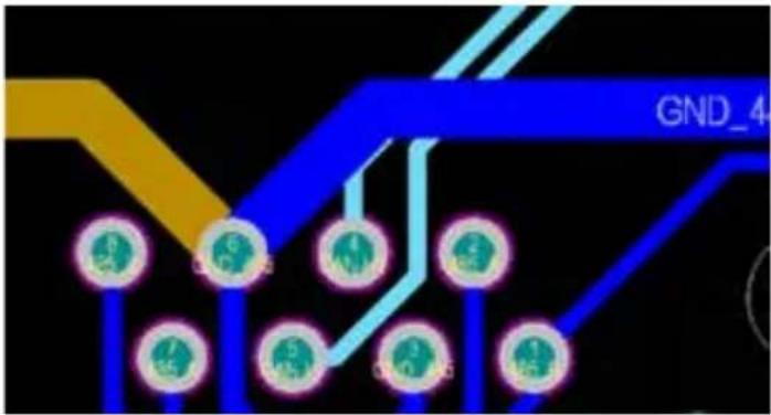
Definition of RJ45 Port Pin for BMS1
| No. | RS485 Pin |
| 1 | 485_B |
| 2 485_A | |
| 3 | GND_485 |
| 4 CAN-H1 | |
| 5 CAN-L1 | |
| 6 GND_485 | |
| 7 485_A | |
| 8 485_B |
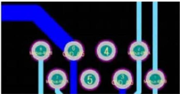
Definition of RJ45 Port Pin for BMS2
| No. | RS485 Pin |
| 1 | 485_B |
| 2 485_A | |
| 3 | GND_485 |
| 4 CAN-H2 | |
| 5 CAN-L2 | |
| 6 GND_485 | |
| 7 485_A | |
| 8 485_B |
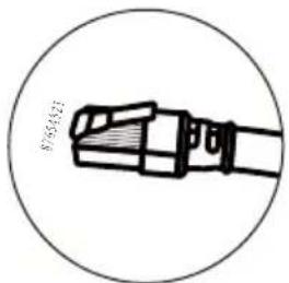

BMS1 Port
BMS2 Port

Definition of RJ45 Port Pin for Meter
| No. | Meter-485 Pin |
| 1 | METER-485_B |
| 2 | METER-485_A |
| 3 | GND_COM |
| 4 | METER-485_B |
| 5 | METER-485_A |
| 6 | GND_COM |
| 7 | -- |
| 8 | -- |
Definition of RJ45 Port Pin for RS485
| No. | RS485 Pin |
| 1 | Modbus-485_B |
| 2 | Modbus-485_A |
| 3 | GND_485 |
| 4 | -- |
| 5 | -- |
| 6 | GND_485 |
| 7 | Modbus-485_A |
| 8 | Modbus-485_B |
RS232
| No. | WIFI/RS232 |
| 1 | |
| 2 | TX |
| 3 | RX |
| 4 | |
| 5 | D-GND |
| 6 | |
| 7 | |
| 8 | |
| 9 | 12Vdc |

Meter Port
![graph TD A["8"] --> B["6"] B --> C["4"] C --> D["2"] D --> E["1"] E --> F["5"] F --> G["3"] G --> H["7"] H --> I["8"] style A fill:#99ccff,stroke:#333 style B fill:#99ccff,stroke:#333 style C fill:#99ccff,stroke:#333 style D fill:#99ccff,stroke:#333 style E fill:#99ccff,stroke:#333 style F fill:#99c…](/content/2026/05/1064019/images/916b6032a22a04d9398aebba26652ea2635d7746453781eabc606975e317f096.jpg)

RS485 Port

WIFI/RS232
This RS232 port is used to connect the wifi datalogger
10. Appendix II
- Split Core Current Transformer (CT) dimension: (mm)
- Secondary output cable length is 4m.

11. EU Declaration of Conformity
within the scope of the EU directives
• Electromagnetic compatibility 2014/30/EU (EMC)
• Low Voltage Directive 2014/35/EU (LVD)
- Restriction of the use of certain hazardous substances 2011/65/EU (RoHS)
CE
NINGBO DEYE INVERTER TECHNOLOGY CO., LTD. confirms herewith that the products described in this document are in compliance with the fundamental requirements and other relevant provisions of the above mentioned directives. The entire EU Declaration of Conformity and certificate can be found at https://www.deyeinverter.com/download/#hybrid-inverter-5.
EUDeclarationofConformity
Product:HybridInverter
Models:SUN-5K-SG01HP3-EU-AM2;SUN-6K-SG01HP3-EU-AM2;SUN-8K-SG01HP3-EU-AM2;
SUN-10K-SG01HP3-EU-AM2; SUN-12K-SG01HP3-EU-AM2; SUN-15K-SG01HP3-EU-AM2;
SUN-20K-SG01HP3-EU-AM2; SUN-25K-SG01HP3-EU-AM2;
Nameandaddressofthemanufacturer:NingboDeyelnverterTechnologyCo.,Ltd.
No.26SouthYongJiangRoad,Daqi,Beilun,NingBo,China
This declaration of conformity is issued under the responsibility of the manufacturer. Also this product is under manufacturer's warranty.
This declaration of conformity is not valid and longer: if the product is modified, supplemented or changed in any other way, as well as incas the product is used or installed improperly.
TheobjectofthedeclarationdescribedaboveisinconformitywiththerelevantUnionharmonizationlegislation:
TheLowVoltageDirective(LVD)2014/35/EU;theElectromagneticCompatibility( EMC)Directive2014/30/EU;the restrictionoftheuseofcertainhazardoussubstances(RoHS)Directive2011/65/EU.
Referencestotherelevantharmonizedstandardsusedorreferencestotheothertechnicalspecificationsin relationtowhichconformityisdeclared:
| LVD: | |
| EN62109-1:2010 | ● |
| EN62109-2:2011 | ● |
| EMC: | |
| ENIEC61000-6-1:2019 | ● |
| ENIEC61000-6-2:2019 | ● |
| ENIEC61000-6-3:2019 | ● |
| ENIEC61000-6-4:2019 | ● |
| ENIEC61000-3-2:2019+A1:2021 | ● |
| EN61000-3-3:2013/A2:2021/AC:2022-01 | ● |
| ENIEC61000-3-11:2019 | ● |
| EN61000-3-12:2011 | ● |
| EN55011:2016/A2:2021 | ● |
NometTitre/NameandTitle:
Aunomde/Onbehalfof:
Date/Date(yyyy-mm-dd):
A/Place:
EUDoC - v1
BardD ai
Senior Sta

NingboDeyeInverterTechnologyCo., Ltd.
2023-10-11
Ningbo,China
NingboDeyeInverterTechnologyCo.,Ltd.
No.26SouthYongJiangRoad,Daqi,Beilun,NingBo,China
NINGBO DEYE INVERTER TECHNOLOGY CO., LTD.
Add.: No.26 South YongJiang Road, Daqi, Beilun, NingBo, China.
Tel.: +86 (0) 574 8622 8957
Fax.: +86 (0) 574 8622 8852
E-mail: service@deye.com.cn
Web.: www.deyeinverter.com

- USER MANUAL
- CONTENTS
- ABOUT THIS MANUAL
- HOW TO USE THIS MANUAL
- SAFETY INTRODUCTIONS
- SAFETY SIGNS
- PRODUCT INTRODUCTIONS
- 2.1 PRODUCT OVERVIEW
- 2.2 PRODUCT SIZE
- 2.3 PRODUCT FEATURES
- 2.4 BASIC SYSTEM ARCHITECTURE
- 2.5 PRODUCT HANDLING REQUIREMENTS
- INSTALLATION
- 3.1 PARTS LIST
- 3.2 MOUNTING INSTRUCTIONS
- INSTALLATION PRECAUTION
- CONSIDERING THE FOLLOWING POINTS BEFORE SELECTING WHERE TO INSTALL
- MOUNTING THE INVERTER
- 3.3 BATTERY CONNECTION
- SAFETY HINT
- BMS CONNECTION
- 3.3.2 FUNCTION PORT DEFINITION
- 3.4 GRID CONNECTION AND BACKUP LOAD CONNECTION
- PLEASE FOLLOW BELOW STEPS TO IMPLEMENT GRID, LOAD AND GEN PORT CONNECTION
- 3.5 PV CONNECTION
- 3.5.1 PV MODULE SELECTION
- 3.5.2 PV MODULE WIRE CONNECTION
- WARNING
- NOTE
- 3.7 EARTH CONNECTION(MANDATORY)
- 3.8 WIFI CONNECTION
- 3.10 WIRING DIAGRAM
- 3.12 THREE PHASE PARALLEL CONNECTION DIAGRAM
- OPERATION
- 4.1 POWER ON/OFF
- 4.2 OPERATION AND DISPLAY PANEL
- LCD DISPLAY ICONS
- 5.1 MAIN SCREEN
- 5.1.1 LCD OPERATION FLOW CHART
- 5.2 SOLAR POWER CURVE
- THIS IS SOLAR PANEL DETAIL PAGE
- THIS IS INVERTER DETAIL PAGE
- THIS IS LOAD DETAIL PAGE
- THIS IS GRID DETAIL PAGE
- 5.3 CURVE PAGE-SOLAR & LOAD & GRID
- 5.4 SYSTEM SETUP MENU
- 5.5 BASIC SETUP MENU
- 5.6 BATTERY SETUP MENU
- THIS IS BATTERY SETUP PAGE
- THIS IS GRID CHARGE, YOU NEED SELECT. ②
- 5.7 SYSTEM WORK MODE SETUP MENU
- WORK MODE
- FOR EXAMPLE
- 5.8 GRID SETUP MENU
- GRID MODE
- GRID SETTING/CONNECT
- GRID SETTING/IP PROTECTION
- 5.9 GENERATOR PORT USE SETUP MENU
- SMART LOAD OFF BATT
- SMART LOAD ON BATT
- 5.10 ADVANCED FUNCTION SETUP MENU
- 5.11 DEVICE INFO SETUP MENU
- MODE
- MODE III: WITH SMART-LOAD
- MODE IV: AC COUPLE
- LIMITATION OF LIABILITY
- APPENDIX I
- APPENDIX II
- EU DECLARATION OF CONFORMITY
- EUDECLARATIONOFCONFORMITY
- PRODUCT:HYBRIDINVERTER
- NOMETTITRE/NAMEANDTITLE
- NINGBO DEYE INVERTER TECHNOLOGY CO., LTD
Brand : V-TAC
Model : SUN-20K-SG01HP3-EU-AM2
Category : Battery charger