
VT-48160 - Battery charger V-TAC - Free user manual and instructions
Find the device manual for free VT-48160 V-TAC in PDF.


| Product Type | Lithium-ion Energy Storage Battery (Wall-mounted) |
| Model | VT-48160 |
| Brand | V-TAC |
| Nominal Voltage | 48 V / 51.2 V |
| Capacity | 160 Ah / 220 Ah |
| Ingress Protection | IP20 |
| Communication Interfaces | RS485 (2x), CAN, RS232, Bluetooth/WiFi/GSM (optional) |
| Operating Temperature (Charge) | 0°C to 55°C |
| Operating Temperature (Discharge) | -20°C to 60°C |
| Storage Temperature | -10°C to 55°C (recommended 20°C to 30°C) |
| Relative Humidity (Storage) | 35% to 85% RH |
| Max Parallel Units | 15 |
| Battery Chemistry | Lithium-ion |
| Display | HMI screen with battery status indicators |
| DC Connection | Anderson connector, 25 mm² cable |
| Safety Features | Overvoltage, undervoltage, overcurrent, short circuit, temperature protection |
| Weight | Approximately 40-55 kg (depending on capacity) |
| Dimensions | Wall-mounted, typical dimensions: ~600x400x150 mm (estimated) |
| Warranty | See manual for warranty terms |
Frequently Asked Questions - VT-48160 V-TAC
User questions about VT-48160 V-TAC
0 question about this device. Answer the ones you know or ask your own.
Ask a new question about this device
Download the instructions for your Battery charger in PDF format for free! Find your manual VT-48160 - V-TAC and take your electronic device back in hand. On this page are published all the documents necessary for the use of your device. VT-48160 by V-TAC.
USER MANUAL VT-48160 V-TAC
This document mainly introduces the product introduction, application scenario, installation, commissioning, system maintenance and technical data of wall mounted household energy storage battery and battery expansion module.
Reader object:
This document is mainly applicable to the following Engineers:
◆ Marketing Engineer
◆ System Engineer
◆ Technical support engineer
Symbolic Convention:
The following symbols may appear in this article, and they represent the following meanings:
| Symbol | Explanation |
 | Indicates a hazard with high risk that will lead to death or serious injury if not avoided. |
 | Indicates a hazard with medium risk that may lead to death or serious injury if not avoided. |
 | Indicates a hazard with low-level risk that may cause slight or moderate injury if not avoided. |
 | It is used to transmit equipment or environmental safety warning information. If not avoided, it may lead to equipment damage, data loss, equipment performance degradation or other unpredictable results.The "instructions" do not involve personal injury. |
 Explanation Explanation | Indicates a hazard with high risk that will lead to death or serious injury if not avoided. |
Explanation
Catalog
1. Safety precautions .... 1
1.1 General security .... 1
1.2 Personnel requirements 4
1.3 Electrical safety 4
2 Product introduction .... 5
2.1 Product introduction 5
2.2 Appearance description 6
2.3 System diagram 7
3 Product installation 8
3.1 Unpacking inspection 8
3.2 Basic installation requirements 8
3.3 Ladder use safety 10
3.4 Drilling safety 10
3.5 Safety of handling heavy objects 10
3.6 Installation guidelines .... 10
4 Electrical connection ..... 11
4.1 Cable connection 11
4.2 communication line connection 12
4.2.1 RS485 communication point definition 12
4.2.2 CAN communication point definition 12
4.2.3 RS232 communication point definition 12
4.3 System connection diagram 13
4.4 Battery connection 13
4.4.1 Single battery connection 13
4.4.2 Multiple batteries in parallel 14
5 System tuning 15
5.1 Check before power on 15
5.2 Battery function description 15
5.2.1 Buzzer action description 15
5.2.2 Screen 16
5.2.3 RST key description 18
5.2.4 Sleep and wake up 18
5.2.5 Indication description 19
5.3 Wireless kit (optional) 20
6 Battery Monitoring 23
6.1 Software running environment 23
6.2 Connect the upper computer 23
6.3 Interface function 24
6.3.1 Real time monitoring 24
6.3.2 Parallel monitoring 26
6.3.3 Store information 26
6.3.4 Parameter setting 27
6.3.5 System setting 28
6.3.6 Export data 28
6.4 Replacing inverter protocol(optional) 29
7 Maintenance and requirements 30
8 Battery storage requirements 30
9 Warranty products ....31
10 Exemption from liability 31
1. Safety precautions
1.1 General security
Statement
When installing, operating and maintaining the equipment, please read this manual first and follow the signs on the equipment and all safety precautions.
The "notice", "attention", "warning" and "danger" in the manual do not represent all safety precautions to be observed, but only supplement all safety precautions. The company shall not be liable for any violation of general safety operation requirements or safety standards for design, production and use of equipment.
The equipment shall be used in an environment that meets the requirements of design specifications, otherwise it may cause equipment failure, and the resulting equipment function abnormalities or component damage, personal safety accidents, property losses, etc. are not within the scope of equipment quality assurance. The installation, operation and maintenance of the equipment shall comply with local laws, regulations and specifications. The safety precautions in the manual are only a supplement to local laws, regulations and specifications.
The company shall not be liable for any of the following circumstances.
- Do not operate under the service conditions described in this manual.
- The installation and use environment exceeds the provisions of relevant international or national standards.
◆ Disassemble, change the product or modify the software code without authorization.
◆ Failure to follow the operation instructions and safety warnings in the product and documents.
◆ Transportation damage caused by customer's own transportation.
◆ Damage caused by storage conditions not meeting the requirements of product documents.
General requirements

DANGER
Live operation is strictly prohibited during installation.
It is strictly prohibited to install, use and operate outdoor equipment and cables (including but not limited to handling equipment, operating equipment and cables, plug and unplug signal interfaces connected to outdoor, high-altitude operation, outdoor installation, etc.) in severe weather such as lightning, rain, snow and force gale.
- After installing the equipment, the empty packaging materials such as cartons, foam, plastic, tie line should be removed.
In case of fire, evacuate the building or equipment area and press the fire alarm bell or dial the fire alarm telephone. Under no circumstances shall re-enter the burning building.
It is strictly prohibited to artificially alter, damage or block the identification and nameplate on the equipment.
When installing the equipment, use tools to tighten the screws.
◆ Paint scratches during equipment transportation and installation must be repaired in time. It is strictly prohibited to expose the scratched parts to the outdoor environment for a long time.
Do not open the main panel of the device without the permission of the manufacturer.
In any case, do not change the structure and installation sequence of the equipment without the permission of the manufacturer.
It is forbidden to affect the battery terminal components during handling, and it is not allowed to lift and handle through the battery terminal bolts.
It is not allowed to reverse engineer, decompile, disassemble, adapt, implant or other derivative operations on the equipment software, and it is not allowed to study the internal implementation of the equipment in any way.
Personal safety
◆ Wear appropriate personal protective equipment during equipment operation. In case of any fault that may cause personal injury or equipment damage, the operation shall be terminated immediately, the person in charge shall be reported, and effective protective measures shall be taken.
Before using the tool, please master the correct use method of the tool to avoid personal injury and equipment damage.
When the equipment is running, the shell temperature is high and there is a risk of burns. Do not touch it.
In case of battery failure, the temperature may exceed the burn threshold of the touchable surface, and contact should be avoided.
Do not open or damage the battery. The released electrolyte is harmful to the skin and eyes. Avoid contact.
Do not place irrelevant items on the top of the equipment or insert them anywhere in the equipment.
◆ Do not place inflammables around the equipment.
- The battery shall not be placed in the fire to avoid explosion and endanger personal safety.
- Do not place the battery module in water or other liquids.
- Do not short-circuit the battery terminal, which may cause combustion.
◆ The battery may cause the danger of electric shock and large short-circuit current. When using the battery, pay attention to the following precautions :
a) Remove watches, rings or other metal objects.
b) Tools using insulated handles.
c) Wear rubber gloves and boots.
d) Do not place tools or metal parts on the top of the battery.
e) Disconnect the charging power supply before connecting or disconnecting the battery terminal.
Do not use water or detergent to clean the electrical parts inside and outside the cabinet.
Do not stand or lean on or sit on the equipment.
◆ Do not damage each module of the equipment.
When installing the battery module, if the battery module falls or is strongly impacted, the equipment will be damaged. It is strictly prohibited to continue to use, otherwise there will be safety risks (cell leakage, electric shock injury, etc.).
Treatment measures for battery leakage
In case of electrolyte leakage, avoid contact with leaked liquid or gas.
Electrolyte is corrosive and contact may cause skin irritation and chemical burns. In case of contact with battery electrolyte, the following measures shall be taken.
Inhalation: evacuate the contaminated area, enter fresh air immediately, and seek medical help immediately.
Eye contact: immediately flush eyes with plenty of water for at least 15 minutes, do not rub, and seek medical help immediately.
Skin contact: immediately wash the contact area with plenty of water and soap and seek medical help immediately.
Ingestion: seek medical help immediately.
Fire treatment measures
In case of fire, the system should be powered off under the condition of ensuring safety.
Use carbon dioxide, FM-200 or ABC dry powder fire extinguisher to extinguish the fire.
DANGER
When the battery temperature is too high, it will cause battery deformation, damage, electrolyte overflow and toxic gas leakage. Please keep away from it to avoid skin irritation and chemical burns.
Flood emergency measures
◆ Power down the system to ensure personal safety.
If any part of the battery y is flooded, do not touch the battery to avoid electric shock.
Do not use the flooded battery. Contact the battery recycling company for scrapping.
Battery recycling
◆ Please dispose of waste batteries according to local laws and regulations. Do not treat batteries as domestic waste.
If the battery leaks or bulges, please contact technical support or battery recycling company for scrapping.
When the battery is unavailable beyond its service life, please contact the battery recycling company for scrapping.
- Avoid exposing the battery to high temperature or direct sunlight.
◆ Avoid exposing the battery to high humidity or corrosive environment.
1.2 Personnel requirements
- The personnel responsible for the installation and maintenance of this equipment must understand various safety precautions and master the correct operation methods.
- Only qualified professionals or trained personnel are allowed to install, operate and maintain the equipment.
- Only qualified professionals are allowed to dismantle safety facilities and overhaul equipment.
◆ Personnel operating the equipment, including operators, trained personnel and professionals, shall have the special operation qualification required by the local state. - The replacement of equipment or components (including software) must be completed by professionals or authorized personnel.

Explanation
◆ Professionals: those who have training or experience in operating equipment and can understand the potential sources and magnitude of hazards in the process of equipment installation, operation and maintenance.
- Trained personnel: personnel who have received corresponding technical training and have necessary experience, can be aware of the risks that may be brought to him during a certain operation, and can take measures to minimize the risks to himself or other personnel.
◆ Operators: operators who may come into contact with the equipment other than trained personnel and professionals.
1.3 Electrical safety
General requirements

DANGER
Before making electrical connection, please ensure that the equipment is not damaged, otherwise electric shock or fire may be caused.
◆ All electrical connections must meet the national electrical standards.
- The cable provided by the user shall meet the requirements of local laws and regulations.
◆ Use special insulating tools for high voltage operation.
DC operation

DANGER
It is forbidden to install or remove the power line with electricity. When the power cord contacts the conductor, it will produce arc or electric spark, which can lead to fire or personal injury.
Before the electrical connection of the equipment, if the live parts may be touched, the corresponding breaking device at the front level of the equipment must be disconnected.
Before connecting the power cord, confirm that the label identification of the power cord is correct before connecting.
If the equipment has multiple inputs, all inputs of the equipment shall be disconnected, and the equipment can be operated only after the equipment is completely powered off.
Wiring requirements
The use of the cable in high temperature environment may cause aging and damage of the insulating layer. The distance between the cable and the periphery of the heating device or heat source area shall be at least 30mm.
- Similar cables shall be bound together, and different types of cables shall be laid at least 30mm apart. Mutual winding or cross laying is prohibited.
- The cables used must be firmly connected, well insulated and of appropriate specifications.
2.Product introduction
2.1 Product introduction
Function
Li-ion battery y includes only battery modules, which can store and release electric energy according to the requirements of inverter management system. The input and output ports of battery are 48 / 51.2V DC.
- Battery charging: the power control module is connected with the energy storage terminals (BAT +, bat -) of the inverter to charge the battery and store the excess photovoltaic energy in the battery under the control of the inverter.
- Battery discharge: when the photovoltaic energy is insufficient to supply power to the load, the system needs to control the battery to supply power to the load and output the stored battery energy to the load through the inverter.
Model

natural_image
Simple line drawing of a blank rectangular frame with a vertical corner and a small protrusion (no text or symbols)| NO. | Voltage | Capacity | IP Level | ESI |
| 1 | 48V | 160/220Ah | IP20 | Bluetooth |
| WIFI | ||||
| GSM |
2.2 Appearance description

| NO. | Description | Functional Description |
| 1 | Reset key | On/OFF button |
| 2 | ADS Dialer | Display connection address |
| 3 | DO | 1/2 Normally open, closed during fault protection 3/4 Normally open, closed when a low battery alarm signal has occurred |
| 4 | RS485 | RS485 communication interface |
| 5 | CAN | CAN communication interface |
| 6 | RS232 | RS232 communication interface (for battery condition monitoring) |
| 7 | RS485 | RS485 communication interface (Used in communication parallel,and for battery condition monitoring or manufacturer to debug or service) |
| 8 | RS485 | RS485 communication interface (Used in communication parallel,and for battery condition monitoring or manufacturer to debug or service) |
| 9 | Battery+ | Positive terminal |
| 10 | Battery- | Negative terminal |
| 11 | ESI | Expand Bluetooth / WiFi / GSM functions |
| 12 | Ground wire | Battery ground wire |
| 13 | RUN | Work |
| 14 | ALM | Alarm and protection |
| 15 | HMI | Display battery status information |
2.3 System diagram
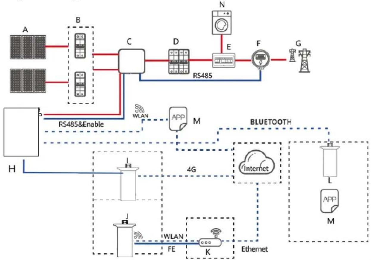
(A) PV module
(B) DC switch
( C) Inverter
(D) AC switch
(E) Power Distribution Box
(F) Intelligent power collector
(G) Power grid
(H) Battery(WALL)
(I) GSM
(J) WIFI
(K) Router
(L) Bluetooth
(M) APP
(N) Load

Explanation
-
The input and output of the battery energy storage system are connected to the energy storage port of the inverter.
◆ Following are the modes to communicate with the battery energy storage system: -
The Inverter can be connected through CAN interface to realize the communication and control between the inverter and battery.
- The battery can be accessed directly through the mobile phone Bluetooth app to view, manage and maintain the performance.
- The battery can be accessed from the public network through WiFi interface to view, manage and maintain the performance.
- The battery can be accessed from the public network through GSM interface to view, manage and maintain the performance.
3.Product installation
3.1 Unpacking inspection
Please confirm whether the outer package of the product is damaged before unpacking. After unpacking, please carefully check the product for damage or missing accessories. In case of damage or missing accessories, please contact the supplier directly for assistance.
A
B

C

D
E

natural_image
Technical line drawing of two mechanical wrenches with threaded ends and adjustment knobs (no text or symbols)F
| NO. | QTY | Description |
| A | 1 | Batter y PACK |
| B | 1 | Instructions |
| C | 6 | Expansion screws M10 |
| D | 1 | MSDS Transportation certificate |
| E | 1 | RS232 communication line |
| F | 1 | Power line 1m |
| G | n | Parallel line:Customized according to customers |
| H | n | RS485 communication line: Customized according to customers |
3.2 Basic installation requirements
◆ Shall be installed in a dry and well-ventilated area to ensure good heat dissipation.
- Recommended to choose a sheltered installation site or under a sunshed, indoor is more preferable option.
- Avoid direct sunlight or rain. The surrounding environment should be clean and free from large infrared radiation, organic solvents and corrosive gases.
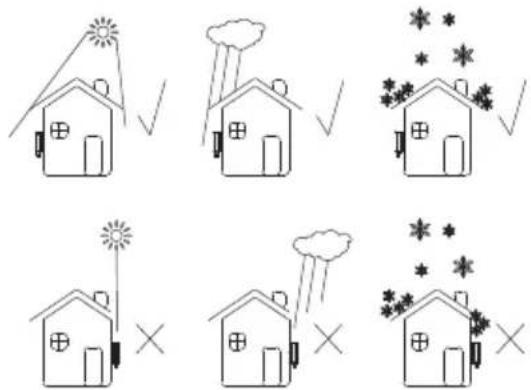
◆ The installation location shall be reasonably away from the fire source.
◆ The installation location shall not be accessible by the children.
The installation location shall be sufficiently away from water sources, such as water tap, sewer pipe, sprinkler etc., to avoid water infiltration.
◆ The installation wall shall be strong enough to carry the weight of the battery for a long time, please follow local standard or best practice guidelines.
Do not place inflammables and explosives around the battery.
When the battery is running, do not block the vent or cooling system. Maintain the battery operating temperature for charging 0-55°C and discharging - 20 \~ 60°C.
Do not store or install the battery in an environment of flammable or explosive gas or smoke. Any operation of the battery in such environment is strictly prohibited.
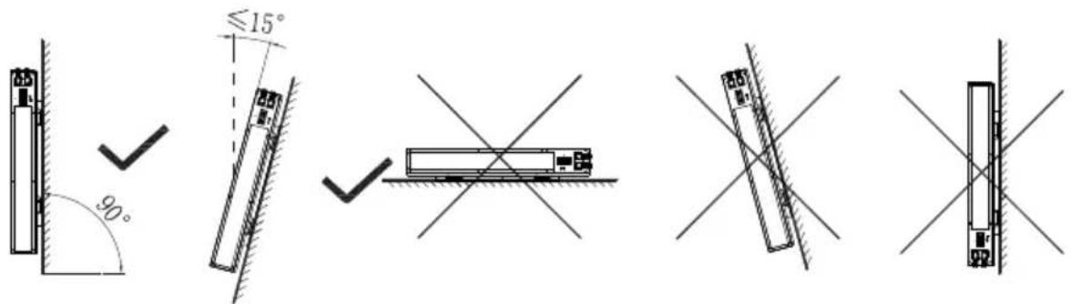
- The battery can be installed on a vertical or backward inclined plane. Please refer to the following figure:
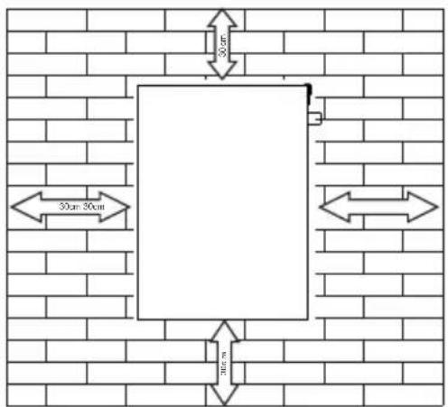
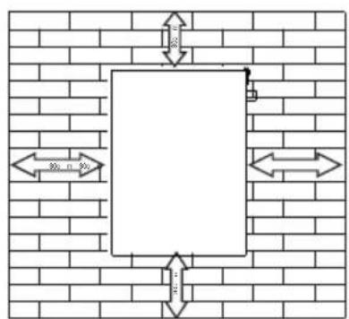
In order to ensure good heat dissipation and convenience in operation and maintenance, sufficient clearance shall be reserved while installing the battery. An example of such clearances are shown in the figure below. Please strictly follow the local battery installation guidelines, where applicable.
3.3 Ladder use safety
◆ Wooden ladder or FRP ladder shall be used when power climbing operation may be involved.
When using the herringbone ladder, the pulling rope must be firm, and someone must hold the ladder during operation.
Before using the ladder, please confirm that the ladder is intact, the bearing weight of the ladder meets the requirements, and overweight is strictly prohibited.
When using the ladder, the wide foot of the ladder shall face down or protective measures shall be taken at the bottom of the ladder to prevent slipping.
The ladder should be placed in a stable place. The gradient of the ladder should be 75°, which can be measured with an angle ruler, as shown in the figure below.

When climbing the ladder, please pay attention to the following actions to reduce danger and ensure safety:
- Keep your body steady.
- The maximum height of operators standing on their feet shall not exceed the fourth step of the ladder from top to bottom.
- Ensure that the center of gravity of the body does not deviate from the edge of the ladder.
3.4 Drilling safety
The following safety precautions shall be considered when drilling on the wall and ground:
◆ Wear goggles and protective gloves when drilling.
During drilling, the equipment shall be covered to prevent debris from falling into the equipment. After drilling, the debris shall be cleaned.
3.5 Safety of handling heavy objects
When carrying heavy objects, be prepared to bear the load to avoid being crushed or sprained by the heavy objects.
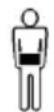
< 18Kg (< 40 lbs)

18\~32Kg (40\~70 lbs)

32\~55Kg (70\~121 lbs)
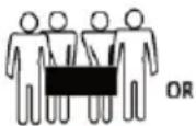
55Kg (>121 lbs)

- When handling the equipment by hand, wear protective gloves to avoid injury.
3.6 Installation guidelines
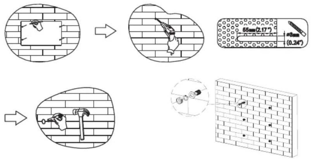
◆ Determine the exact location of battery installation; If it is wall mounted, the wall thickness shall be greater than or equal to 100mm;
◆ Use the mounting bracket or cardboard to determine the specific location of the hole; Keep the top edge of the cardboard horizontal.
- Drill 6 holes at the marked position with the hole diameter of 8; The hole depth shall not be less than 55mm .
◆ Knock 6 expansion screws into the drilled holes.
◆ Hang the battery mounting bracket on the screw.
◆ Lock the nut and fix the battery mounting bracket. Then hang the battery on the mounting bracket.
◆ After adjusting the position of the battery, lock the M6 * 40 screw at the top of the support, fix the battery, and place the battery to slide.
◆ installation is complete.
4. Electrical connection
4.1 Cable connection
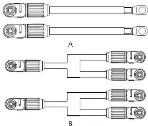
natural_image
Technical line drawings of mechanical components labeled A and B, showing various assembly or connection types (no text or symbols present)Anderson connector is used on the DC input side of the battery energy storage system. The specific connections are as follows:
| NO. | Terminal | Cable diameter | Length | Description |
| A | Anderson/SC25-8 | 25mm^2 | 1-3m | Used for connection between batter y and inverter |
| B | Anderson | 25mm^2 | 1-3m | For batter y parallel connection |
4.2 Communication line connection
4.2.1 RJ45 Communication point definition(8P8C)


natural_image
Pure diagram of three gray bars with yellow and red vertical bars, no text or symbols present| PIN | RS485 | CAN |
| 1 | RS485_B | NC |
| 2 | RS485_A | NC |
| 3 | GND NC | |
| 4 | NC CANL | |
| 5 | NC CANH | |
| 6 | GND NC | |
| 7 | RS485_A | GND |
| 8 | RS485_B | NC |
4.2.2 RJ11 Communication point definition(6P6C)


natural_image
Pure diagram of three parallel gray bars with colored segments, no text or symbols present| PIN | Rs232 |
| 1 | NC |
| 2 | NC |
| 3 | TX |
| 4 | RX |
| 5 | GND |
| 6 | NC |

Explanation
◆ RS232 communication: BMS can communicate with the computer through RS232 interface to check battery health related information including battery voltage, current, temperature, and manufacturer's default data.
◆ RS485 / can communication: CAN communication connects the battery with the inverter to function as duo for operations.
◆ RS485 communication: The additional two RS485 interfaces can be used for parallel connections with other batteries, or, to monitor battery health conditions including debugging and routine servicing. Addresses PIN: 1-15
- Different inverter communication protocols have different pin definitions. Please pay attention to the compatibility between the battery and inverter CAN/RS485 communication line.
4.3 System connection diagram

flowchart
graph TD
    A["PV"] --> B["PV combiner box"]
    B --> C["INVERTER"]
    C --> D["DC Breaker"]
    D --> E["POWER GRID"]
    C --> F["AC Breaker"]
    F --> G["AC Breaker"]
    G --> H["LOAD"]
    style A fill:#f9f,stroke:#333
    style B fill:#ccf,stroke:#333
    style C fill:#cfc,stroke:#333
    style D fill:#fcc,stroke:#333
    style E fill:#ffc,stroke:#333
    style F fill:#cff,stroke:#333
    style G fill:#ffc,stroke:#333
    style H fill:#cfc,stroke:#333
| Cable color | Description | Cable color | Description |
| DC positive wire | Live Wire | ||
| DC negative wire | Naught wire | ||
| Ground wire | Communication line |
4.4 battery connection
4.4.1 Single battery connection

| Cable color | Description | Cable color | Description |
| DC positive wire | RJ45 Communication LineRS485/CAN communication | ||
| DC negative wire | RJ11 Communication Line |
4.4.2 Multiple batteries in parallel

flowchart
graph TD
    A["INVERTER"] -->|PV AG OUT AG IN BAT| B["Battery-1"]
    A -->|PV AG OUT AG IN BAT| C["Battery-2"]
    B --> D["PC"]
    C --> D
    style A fill:#f9f,stroke:#333
    style B fill:#ccf,stroke:#333
    style C fill:#cfc,stroke:#333
    style D fill:#fcc,stroke:#333
The power lines between each battery are the same length
| Cable color | Description | Cable color | Description |
| DC positive wire | RJ11 Communication Line | ||
| DC negative wire | Parallel Communication line | ||
| RJ45 Communication LineRS485/CAN communication |

Explanation
The maximum number of batteries can only be connected in parallel is 15pcs. After parallel connection, the address of ads needs to be assigned, as shown below:
| Address | Dial switch Remark | |||||
| #1 | #2 | #3 #4 | ||||
| 0 | OFF OFF | OFF OFF | ||||
| 1 | ON OFF | OFF OFF | Battery PACK1(Main PACK) | |||
| 2 | OFF ON | OFF OFF | Battery PACK2 | |||
| 3 | ON ON | OFF OFF | Battery PACK3 | |||
| 4 | OFF OFF | ON OFF | Battery PACK4 | |||
| 5 | ON OFF | ON OFF | Battery PACK5 | |||
| 6 | OFF ON | ON OFF | Battery PACK6 | |||
| 7 | ON ON | ON OFF | Battery PACK7 | |||
| 8 | OFF OFF | OFF ON | Battery PACK8 | |||
| 9 | ON OFF | OFF ON | Battery PACK9 | |||
| 10 | OFF ON | OFF ON | Battery PACK10 | |||
| 11 | ON ON | OFF ON | Battery PACK11 | |||
| 12 | OFF OFF | ON ON | Battery PACK12 | |||
| 13 | ON OFF | ON ON | Battery PACK13 | |||
| 14 | OFF ON | ON ON | Battery PACK14 | |||
| 15 | ON ON | ON ON | Battery PACK15 | |||
◆ The inverter only needs to communicate with the host (Pack1).
When multiple batteries are connected with multiple inverters, it is best to connect through the combiner box. If it is not connected through the combiner box, the wiring mode shall be confirmed with the manufacturer's agent. And the cable from each battery to the inverter remains the same length.
Notice
◆ Batteries are not allowed to be connected in series.
- Different batteries with different chemistries, different batches of batteries from the same chemistry and technical design parameters can not be bundled and used together.
5. System tuning
5.1 Check before power on
| NO. | Inspection items Acceptance criteria | |
| 1 | The energy storage battery is installed in place | The installation is correct, firm and reliable. |
| 2 | Reasonable cable layout | The cable layout is reasonable to meet the user's requirements. |
| 3 | Beautiful binding of cable ties | The cable ties shall be uniform and no sharp corners shall be left at the cut. |
| 4 | Reliable grounding | The ground wire is connected correctly, firmly and reliably. |
| 5 | Disconnect switch | "DC switch" and all switches connected to energy storage are in "off" state. |
| 6 | The cable is connected in place | The DC input line, energy storage line and signal line are connected correctly, firmly and reliably. |
| 7 | Insulate unused terminals and interfaces | Install insulating tape on unused terminals and interfaces. |
| 8 | The installation environment meets the requirements | The installation space is reasonable, the environment is clean and tidy, and there is no construction residue. |
After the inspection, press and hold the RST key (3 \~ 6S) and release it, the protection board is activated.
5.2 Battery function description
5.2.1 Buzzer action description
| NO. | Mode | Description |
| 1 | Fault | Beep 0.25S every 1S |
| 2 | Protection | Beep 0.25S every 2S (except over voltage protection) |
| 3 | Alarm | Beep 0.25S every 3S (except over voltage alarm) |

Explanation
The buzzer function can be enabled or disabled by the upper computer. It is disabled by default.
5.2.2 Screen
HMI screen composition
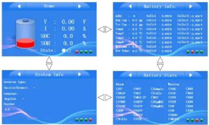
flowchart
graph TD
    A["Home"] --> B["Battery Info."]
    B --> C["System Info"]
    C --> D["Battery State"]
    D --> E["Alarm"]
    E --> F["Power"]
    F --> G["State: 0.0%"]
    style A fill:#f9f,stroke:#333
    style B fill:#ccf,stroke:#333
    style C fill:#cfc,stroke:#333
    style D fill:#fcc,stroke:#333
Home:
| NO. ICON | Description | |
| 1 | [X/BW] | 0% |
| 2 | [7WD2] | 25%=SOC<50% |
| 3 | [XXHC] | 50%=SOC<75% |
| 4 |  | 75%=SOC=100% |
| 5 | [24KC] | SOC=0% |
| 6 | [4CZB] | Battery Alarm Status |
Battery Information:
| NO. | NOItems | Description | Items | Description | |
| 1 | Addr. | Battery Pack Address | 5 | Env Temp | Environment temperature |
| 2 | Rem Cap | Remnant capacity | 6 | MOS Temp | MOS Temperature |
| 3 | Tol Cap | Total capacity | 7 | Cells1~16 | Battery Cell Voltage |
| 4 | Temp1~4 | Battery Temperature |
Battery Information: Protection Status
| NO. | NQItems | Description | Items | Description | |
| 1 | CP | Short Circuit Protection | 12 | DUTP | Discharge low temperature protection |
| 2 | DOCP | Discharge over current protection | 13 | CUTP | Charge low temperature protection |
| 3 | COCP | Charge over current protection | 14 | DOTP | Discharge high temperature protection |
| 4 | TUVP | Total under voltage protection | 15 | COTP | Charge high temperature protection |
| 5 | TOVP | Total over voltage protection | 16 | PCB | PCB Protection |
| 6 | UVP | Cell over discharge protection | 17 | Sample | Sample Protection |
| 7 | OVP | Cell over voltage protection | 18 | Cells | Battery Cells Protection |
| 8 | Fully | Fully protection | 19 | NTC | NTC Protection |
| 9 | EUT | Low environment temperature protection | 20 | chg MOS | Charge MOS protection |
| 10 | EOT | High environment temperature protection | 21 | dhg MOS | Discharge MOS protection |
| 11 | MOS OT | MOS High temperature protection |
Battery Information: Alarm Status
| NO. | N°tems | Description | Items | Description | |
| 1 | DOC | Discharge over current alarm | 8 | MOS OT | MOS High temperature alarm |
| 2 | COC | Charge over current alarm | 9 | EUT | Low environment temperature alarm |
| 3 | TUV | Total over discharge alarm | 10 | EOT | High environment temperature alarm |
| 4 | TOV | Total over charge alarm | 11 | DUT | Discharge low temperature alarm |
| 5 | UV | Cell over discharge alarm | 12 | CUT | Charge low temperature alarm |
| 6 | OV | Cell over discharge alarm | 13 | DOT | Discharge high temperature alarm |
| 7 | USOC | Low SOC alarm | 14 | COT | Charge high temperature alarm |

Explanation
♦ Battery is in protection state:
◆ Battery is in normal state:
♦ Battery is in alarm:
System Information Interface
| NO. | Items | Description |
| 1 | Inverter | Support 10 kind of inverters, we will still upgrade. |
| 2 | Language Setting | 3 Languages for setting |
5.2.3 RST key description
| NO. | Mode | Description |
| 1 | Fault | BMS is in sleep state, press the key (3 ~ 6S) and release it, the protection board is activated, and the LED indicator lights up successively from "run" for 0.5 seconds. |
| 2 | Dormancy | BMS is in the active state. Press the key (3 ~ 6S) and release it, the protection board is dormant, and the LED indicator lights up successively from the lowest power light for 0.5 seconds. |
| 3 | Reset | BMS is active. Press the key (6 ~ 10s) and release it, the protection board is reset, and all LED lights are on for 1.5 seconds at the same time. |

Explanation
After the BMS is reset, it still retains the parameters and functions set by the upper computer. If it needs to be restored to the initial parameters, it can be realized through the "restore default value" of the upper computer, but the relevant operation records and stored data remain unchanged (such as power, cycle times, protection records, etc.).
5.2.4 Sleep and wake up
Sleep:
When any of the following conditions occurs, the system enters into the low power consumption mode:
◆ Single or overall over discharge protection is not released within 30 seconds.
◆ Press the key (3 \~ 6S) and release the key.
The minimum monomer voltage is lower than the sleep voltage, and the duration reaches the sleep delay time (no communication, no protection, no balance and no current).
◆ The standby time exceeds 24 hours (no communication, no charge and discharge, no mains power).
◆ Forced shutdown by upper computer software.
Notice
To enable forced sleep mode, ensure that the input terminal is not connected to the external voltage, otherwise it will not be able to enter the low power consumption mode.
Wake up:
When the system is in the low power consumption mode and meets any of the following conditions, the system will exit the low power consumption mode and enter into the normal operation mode:
- Connect the charger, and the output voltage of the charger shall be greater than 48V. (the battery voltage of 16 strings needs to be greater than 51.2V)
- Press the key (3 \~ 6S) and release the key.
◆ Activation of RS232 interface.
Notice
After single or overall over discharge protection, enter the low power consumption mode, wake up regularly every 4 hours, and turn on the charge discharge MOS. If it can be charged, it will exit the sleep state and enter normal charging; If the Automatic wake-up fails to charge for 10 consecutive times, it will no longer wake up automatically.
When the system is defined as that the recovery voltage is not reached after 2 days of standby (standby time setting value) after the end of charging, it is forced to resume charging until the end of recharging.
5.2.5 Indicator Description
HMI Screen: There are 2LEDS on front panel to show the battery working status.
| PACK Status | Normal/Alarm/Protection | RUN | ALM | Remark |
| Power Off | Sleep | OFF | FF | All off |
| Standby | Normal | Flash 1 | OFF | Standby state |
| Alarm | Flash 1 | Flash 3 | Cell low voltage | |
| Charge | Normal | ON | OFF | The maximum power LED flashes (flashes 2), and the overcharge alarm ALM does not flash |
| Alarm | ON | Flash 3 | ||
| Over Charge protection | ON | OFF | If there is no mains power, LED as standby | |
| Temperature/Over current Fault/Protection | OFF | ON | Close charge | |
| Discharge | Normal | Flash 3 | OFF | |
| Alarm | Flash 3 | Flash 3 | ||
| Under Discharge Protection | OFF | OFF | Close discharge | |
| Temperature/Over current Short circuit/Fault/Protection | OFF | ON | ||
| Fault | OFF | ON | Close charge/discharge |
5.3 wireless kit(Optional)
The wireless kit is divided into three modules:
◆ WIFI
♦ GSM
Bluetooth
Each module is an independent module, which module can be confirmed by label.
Outline drawing of wireless Kit
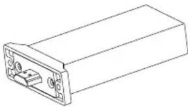
natural_image
Line drawing of a rectangular electronic device with ports and a central connector (no text or symbols)Connecting wireless kit:
◆ Insert the module into the battery wireless kit port, download the wireless kit app, and register the account after installation.
◆ After turning on Bluetooth / WiFi / GSM, click Add device.

Explanation
◆ The maximum connection range of Bluetooth is only 12 meters.
◆ GSM needs to be plugged in the corresponding SIM card and use network services. The installation method of SIM card is shown in the figure below:

natural_image
Simple line drawing of a mechanical device with an arrow indicating direction (no text or symbols)
App interface description and operation steps


User registration
Switch to "ME" in the lower right corner of APP.
◆ Click the avatar position to register.
◆ "Language" for language switching, supporting 3 languages.
Add device
Click "home" in the lower left corner of the app to switch to the add product module.
◆ Click "Add Device" or "+" to add products.
The "Message" is after-sales service.
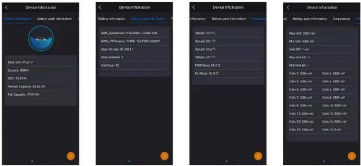
Click the connected batter y to view the following information:
Battery information
- You can view the relevant information of battery voltage, working current and capacity.
Battery pack information
- You can view the number information of battery accessories.
Temperature
- You can view the temperature information of each part of the battery.
Voltage
- You can view the information about the cell voltage.


Alarm
- You can view battery alarm related information.
| NO. | NOItems | Description | Items | Description | |
| 1 | DOC | Discharge over current alarm | 8 | MOS OT | MOS High temperature alarm |
| 2 | COC | Charge over current alarm | 9 | EUT | Low environment temperature alarm |
| 3 | TUV | Total over discharge alarm | 10 | EOT | High environment temperature alarm |
| 4 | TOV | Total over charge alarm | 11 | DUT | Discharge low temperature alarm |
| 5 | UV | Cell over discharge alarm | 12 | CUT | Charge low temperature alarm |
| 6 | OV | Cell over discharge alarm | 13 | DOT | Discharge high temperature alarm |
| 7 | USOC | Low SOC alarm | 14 | COT | Charge high temperature alarm |
Protection
- You can view information about battery protection.
| NO. | NOLtems | Description | Items | Description | |
| 1 | CP | Short Circuit Protection | 12 | DUTP | Discharge low temperature protection |
| 2 | DOCP | Discharge over current protection | 13 | CUTP | Charge low temperature protection |
| 3 | COCP | Charge over current protection | 14 | DOTP | Discharge high temperature protection |
| 4 | TUVP | Total under voltage protection | 15 | COTP | Charge high temperature protection |
| 5 | TOVP | Total over voltage protection | 16 | PCB | PCB Protection |
| 6 | UVP | Cell over discharge protection | 17 | Sample | Sample Protection |
| 7 | QVP | Cell over voltage protection | 18 | Cells | Battery Cells Protection |
| 8 | Fully | Fully protection | 19 | NTC | NTC Protection |
| 9 | EUT | Low environment temperature protection | 20 | chg MOS | Charge MOS protection |
| 10 | EOT | High environment temperature protection | 21 | dhg MOS | Discharge MOS protection |
| 11 | MOS OT | MOS High temperature protection |
6.Battery Monitoring
6.1 Software running environment
The software runs on PC and it is compatible to use Windows operating system. The system environment requires the support of Microsoft .Net Framework version 2.0 or above. Please confirm that it has been installed before use. The installation is as follows:

◆ Download Microsoft .Net framework
◆ Double click the downloaded program to install it
This software does not need to be installed independently, but only needs to meet the environment. Double click the main program icon to run it.

6.2 Connect the upper computer
◆ Ensure that the BMS board is normally powered on and not in sleep state, the crystal head of the communication line is inserted into the communication port of the protection board, and the USB end is inserted into the computer.
◆ Double click to start the upper computer.
◆ Click the "try to connect" button to search the serial port to try to connect. Or manually select the serial port and click the "open serial port" button link.

Explanation
If connection fails for the following reasons, the resolutions are:
◆ Using the wrong host computer: Method: replace the correct version of the upper computer.
◆ Poor communication line or wrong wiring:
Method: replace the communication line or correct the wrong wiring.
◆ The computer USB interface is not recognized: Method: change a USB interface
- Drive not installed:
Method: install the driver corresponding to the communication line.
Method for judging whether the communication line driver has been installed:
◆ Check whether there is a relevant COM port in the "serial port" drop-down of the upper computer. If it is not found, it may not be installed.
- Press the win key and R key at the same time to open the [run] window, enter the devmgmt.msc command, and open the [device manager].
6.3 Interface function
6.3.1 Real time monitoring
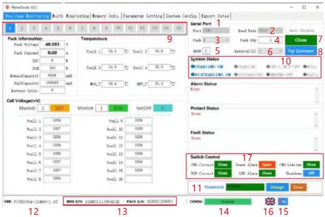
| NO. | Item | Description |
| 1 | Serial port | Serial port: you can select the drop-down item to select the serial port to communicate. (Note: available when the serial port is not opened) |
| 2 | Baud rate | Baud rate: you can select the drop-down item to select the baud rate of communication. (Note: available when the serial port is not opened) |
| 3 | PACK | Pack : the drop-down item can be selected. When FF is selected, access the RS232 interface of the host to obtain all pack data. (Note: available when the serial port is not opened) |
| 4 | PACK QTY | Number of packs: the total number of packs read by the upper computer from the BMS board (when applied to multiple computers in parallel, the pack data is obtained from the main pack). |
| 5 | ADDR | Address: the currently read BMS address value. |
| 6 | Intervals | Interval (seconds): optional. The interval between the upper computer reading data from the BMS board. |
| 7 | Close | Turn on the serial port: turn on or off the serial port by alternating the function buttons. |
| 8 | Try connect | Try to connect: search for available serial ports and open them. |
| 9 | Pack serial number group | The data key, which is the package serial number, displays the package being read and presented on the current interface with white words on a blue background; |
| "Auto" key, alternate function buttons. Available when FF is selected for pack in 3 and monitoring is started, i.e. each pack data is displayed automatically in cycle (when applied to multiple machines in parallel). | ||
| 11 | Administrator password column | Some setting functions can only be used after entering the administrator password. When the password is entered correctly, the input box will turn green. At this time, you have obtained the authority of the administrator. |
| 12 | Version | software version number of BMS. |
| 13 | S/N | Barcode and pack s / N of BMS board. |
| 14 | Monitor communication status | Communication status between upper computer and BMS board. |
| 15 | Screenshot function | Click to enter the screenshot status, and the toolbar will appear after marking out the screenshot area with the mouse. |
| 16 | Flag Icon | Displays the flag icon of the current language country. Click to switch languages. |
| 17 | Switch control | When the button is red, it indicates that the function processing is off, and when it is green, it indicates that it is on. |

Explanation
◆ Try to connect:
First set the baud rate and pack on the upper computer, connect the BMS board with the RS232 communication line, then insert the USB interface of the RS232 communication line into the USB port of the computer, and then click the "try to connect" button to automatically search and open the effective serial port.
Automatic rotation pack:
When FF is selected in the "pack" drop-down item, the "rotation" check box in the interface becomes available. Check it to use the rotation function. Uncheck it to cancel the rotation function.

◆ Change Password:
Click the "Change" button at the bottom right of the interface to pop up the password modification window. Enter the old password and the new password and then confirm. Note: there is no function to retrieve the password. Please remember the modified new password.

◆ Get administrator privileges:
Enter the administrator password in the "administrator password" input box at the bottom right of the interface. After correctly entering the password, the input box turns green. At this time, you have obtained administrator permission.

6.3.2 Parallel monitoring
◆ Interface:
Click the main interface tab [Multi Monitoring] to enter the interface.

◆ To the Bottom:
Check "To the Bottom" at the bottom left to display the monitored real-time data in the data area. Note: this function only displays the data on the interface, and the data has not been saved.
◆ Clear interface data:
Click the button "CLS" to clear the real-time data on the interface.
◆ Record data
Check "Data save to database" to start recording data. When there is data recording, the number of saved data will appear on the right.
◆ Export data
Click the "Export" button to export the recorded real-time data. You can also export on the export data page.
6.3.3 Store information.
◆ Interface:
Click the main interface tab [Memory Info.] to enter the interface.
◆ Read / write BMS time:
Click the "Read BMS" button on the upper right to read the BMS time.
Click the "Write To BMS" button on the upper right to write the BMS time.
◆ Storage settings:
Range: start sequence number and maximum sequence number.
Read records: read stored records.
Pause / continue: when reading, click "pause" to read, and then click again to continue reading.
Save record: save the record on the interface to local.
Delete record: delete the storage record of BMS board.


Explanation
when reading, the prompt "no more data" indicates that the reading has been completed.
6.3.4 Parameter setting
◆ Interface:
Click the main interface tab [Parameter Setting] to enter the interface.

◆ Function:
Read parameters: read all parameters in the interface.
Write parameters: overwrite BMS parameters. This operation requires administrator privileges.
Restore default parameters: restore all parameters to the default parameters. The default parameters are from the preset parameters in BMS. This operation requires administrator privileges.
Import parameters: read the data in the local file into this interface. Note: the data is only read on the interface and has not been written into the BMS. If you need to write, please execute the write operation.
6.3.5 System settings
◆ Interface:
Click the main interface tab [System Config.] to enter the interface.

function:
Just follow the interface prompts. Some function operations require administrator privileges.
6.3.6 Export data
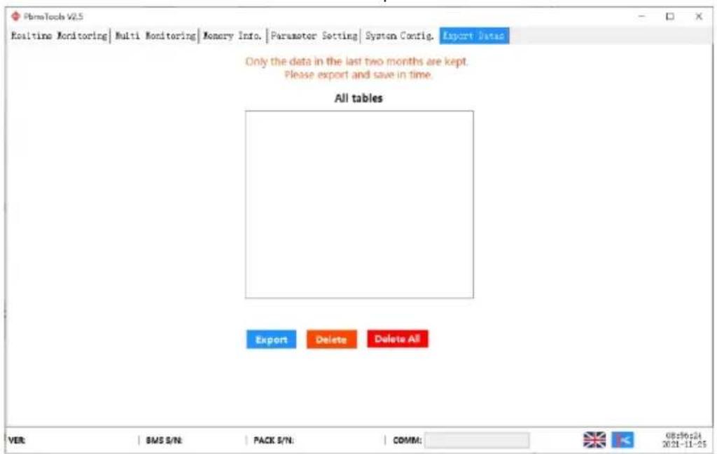
After checking "record data" on the [parallel monitoring] page, the recorded data can be exported on this page. The table is named after the starting time point of the record. The data can be saved for up to two months, and the expired data will be automatically cleared. You can double-click the table name to export data.
6.4 Replacing inverter protocol on battery monitoring(Optional)
Software running environment
This function can only be realized by installing the protocol conversion board. Before using this function, please confirm whether the protocol conversion board is installed on this battery.
This software does not need to be installed independently, but only needs to meet the environment. Double click the main program icon to run it.
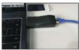
◆ Connect the computer to the battery via the USB-RS485 communication cable.
natural_image
Close-up of a black USB device connected to a blue cable, with a laptop keyboard visible on the left (no text or symbols)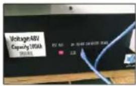
Setting for DID.

◆ Click to open the Inverter software on the PC.
◆ Select the right serial port.


◆ Click the "Read" button to read the current inverter code.
◆ Click the "Write" button the inverter code that you need.
Click the "Read" button to read the inverter code again, and confirm whether the operation was successful or not.
◆ Reference table of different inverter code.


7. Maintenance and replacement
◆ Please maintain the equipment when you are familiar with and understand the contents of this manual and have appropriate tools and test devices.
Before carrying out maintenance work, please power down the equipment first, then follow the instructions of the delayed discharge label and wait for the corresponding time to ensure that the equipment has been powered down before operating the equipment.
During maintenance, please try to avoid irrelevant personnel entering the maintenance site, and temporary warning signs or fences must be erected for isolation.
◆ If the equipment fails, please contact your dealer in time.
The equipment can be powered on again only after the fault is handled, otherwise it may cause fault expansion or equipment damage.
Do not open the cover plate without authorization, otherwise there will be a risk of electric shock, and the resulting failure does not belong to the scope of warranty.
◆ Operation and maintenance personnel and professional technicians shall be fully trained in safe use and equipment maintenance, and shall operate with sufficient preventive measures and personal protective equipment.
◆ Battery maintenance shall be performed or supervised by personnel familiar with the battery y and its required precautions.
◆ After the maintenance operation, check immediately to ensure that no tools or other parts are missing in the equipment.
8. Battery storage requirements
When the battery is stored, it shall be placed correctly according to the identification of the packing box, and shall not be placed upside down or on the side.
- When the battery packing box is stacked, it shall meet the stacking requirements on the outer package.
- The battery shall be handled with care, and it is strictly prohibited to damage the battery y.
◆ Storage environment requirements:
a. Ambient temperature: - 10 °C \~ 55°C, recommended storage temperature: 20 ? \~ 30 ?.
b. Relative humidity: 35% RH \~ 85% RH.
c. Dry, ventilated and clean.
d. Avoid contact with corrosive organic solvents, gases and other substances.
e. Avoid direct sunlight.
f. The distance from the heat source shall not be less than two meters.
When the battery y is stored, it must be disconnected from the outside. If there is an indicator on the battery panel, the indicator should be off.
The warehouse keeper shall count the battery storage every month and regularly report the battery inventory to the planning link. For batteries with storage time close to -20 \~ 25°C = 6 months and -20 \~ 45°C = 1 month, replenishment shall be arranged in time. The battery shall be charged once every three months (under the normal storage environment, long-term storage will lead to capacity attenuation and cycle life decline. If it exceeds the storage environment requirements, it will further aggravate the capacity attenuation and cycle life decline.)
When the stored batteries are shipped, the principle of first in first out shall be followed.
◆ Battery maintenance shall be performed or supervised by personnel familiar with the battery and its required precautions.
◆ After the battery production test is completed, it needs to be supplemented to 30-50% SOC at least before storage.
9.Warranty products
Requirement:
During the warranty period, the company requires customers to provide invoices and dates for purchasing products. At the same time, the trademark on the product shall be clearly visible, otherwise it has the right not to provide quality assurance. The replaced products shall be handled by the company, and the customer shall leave a certain time for the company to deal with the faults.
10. Exemption from liability
The company has the right not to conduct quality assurance under the following circumstances:
◆ Beyond the free warranty period.
◆ Incorrect installation, modification or use.
◆ Operate in very harsh environments beyond those described in this manual.
◆ Failure due to damage caused by unauthorized installation, repair, change or disassembly.
◆ Failure due to damage caused by the use of non-standard components or software.
◆ Any installation and use beyond the scope specified in relevant international standards.
◆ Damage caused by abnormal natural environment.
CORE OF THE BRAND
What we truly are.

- Reader object:
- Symbolic Convention:
- Explanation
- Catalog
- Safety precautions .... 1
- Product introduction .... 5
- Product installation 8
- Electrical connection ..... 11
- System tuning 15
- Battery Monitoring 23
- Maintenance and requirements 30
- Battery storage requirements 30
- Warranty products ....31
- Exemption from liability 31
- Safety precautions
- General security
- Statement
- General requirements
- DANGER
- Personal safety
- Treatment measures for battery leakage
- Fire treatment measures
- Flood emergency measures
- Battery recycling
- Personnel requirements
- Electrical safety
- DC operation
- Wiring requirements
- 2.Product introduction
- Product introduction
- Function
- Model
- Appearance description
- System diagram
- 3.Product installation
- Unpacking inspection
- Basic installation requirements
- Ladder use safety
- Drilling safety
- Safety of handling heavy objects
- Installation guidelines
- Electrical connection
- Cable connection
- Communication line connection
- RJ45 Communication point definition(8P8C)
- RJ11 Communication point definition(6P6C)
- System connection diagram
- battery connection
- Single battery connection
- Multiple batteries in parallel
- Notice
- System tuning
- Check before power on
- Battery function description
- Buzzer action description
- Screen
- RST key description
- Sleep and wake up
- Sleep:
- Wake up:
- Indicator Description
- wireless kit(Optional)
- App interface description and operation steps
- User registration
- Add device
- Alarm
- Protection
- 6.Battery Monitoring
- Software running environment
- Connect the upper computer
- Interface function
- Real time monitoring
- ◆ Get administrator privileges:
- Parallel monitoring
- ◆ Interface:
- ◆ To the Bottom:
- ◆ Clear interface data:
- ◆ Record data
- ◆ Export data
- Store information.
- ◆ Read / write BMS time:
- ◆ Storage settings:
- Parameter setting
- ◆ Function:
- System settings
- function:
- Export data
- Replacing inverter protocol on battery monitoring(Optional)
- Maintenance and replacement
- Battery storage requirements
- 9.Warranty products
- Requirement:
- Exemption from liability
- CORE OF THE BRAND
Brand : V-TAC
Model : VT-48160
Category : Battery charger