MSD51 - Pump Maruyama - Free user manual and instructions
Find the device manual for free MSD51 Maruyama in PDF.


| Product Type | Power Sprayer (Pump) |
| Brand | Maruyama |
| Model | MSD51 |
| Overall Length | 235 mm |
| Overall Width | 337 mm |
| Overall Height | 176 mm |
| Weight | 7.8 kg |
| Revolving Speed | 3600 rpm |
| Suction Capacity | 40 L/min |
| Maximum Pressure | 40 kgf/cm² |
| Required Power | 5.0 PS |
| Inlet Tap Thread | G1 |
| Outlet Tap Thread | G1/2 |
| Lubricating Oil | SC GRADE SAE10W-30 |
| Lubricating Oil Capacity | 0.4 L |
| Intended Use | Agricultural and irrigation (not industrial) |
| Precautions | Avoid chemicals, seawater, hot water; follow chemical manual |
| Maintenance | Replace crankcase oil after 50 hours of operation |
| Inspection | Check discharge valve and piston packing for wear |
Frequently Asked Questions - MSD51 Maruyama
User questions about MSD51 Maruyama
0 question about this device. Answer the ones you know or ask your own.
Ask a new question about this device
Download the instructions for your Pump in PDF format for free! Find your manual MSD51 - Maruyama and take your electronic device back in hand. On this page are published all the documents necessary for the use of your device. MSD51 by Maruyama.
USER MANUAL MSD51 Maruyama
OWNER'S/OPERATOR'S MANUAL
POWER SPRAYER MSD51
Main parts nomenclature

Specifications
| Model | MSD51 | |
| Overall height | Overall length(mm) | 235 |
| Overall width(mm) | 337 | |
| Overall height(mm) | 176 | |
| Weight(kg) | 7.8 | |
| Specifications | Revolving speed(rpm) | 3600 |
| Suction capacity(1/min) | 40 | |
| Pressure(kgf/cm2) | 40 | |
| Required power(PS) | 5.0 | |
| Inlet tap thread | G1 | |
| Outlet tap thread | G1/2 | |
| Lubricating oil | SC GRADESAE10W-30 | |
| Lubricating oil capacity(L) | 0.4 | |
Performance curve
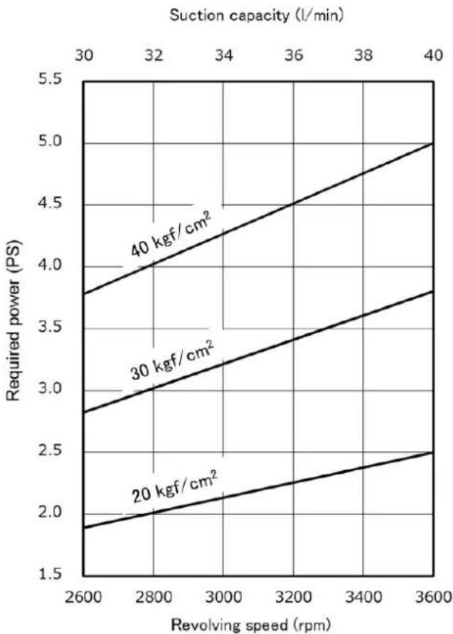
line
| Revolving speed (rpm) | Required power (PS) for 20 kgf/cm² | Required power (PS) for 30 kgf/cm² | Required power (PS) for 40 kgf/cm² | | --------------------- | ---------------------------------- | ---------------------------------- | ---------------------------------- | | 2600 | 1.9 | 2.8 | 3.8 | | 2800 | 2.0 | 3.0 | 4.0 | | 3000 | 2.1 | 3.2 | 4.2 | | 3200 | 2.2 | 3.4 | 4.4 | | 3400 | 2.3 | 3.6 | 4.6 | | 3600 | 2.5 | 3.8 | 5.0 |*To be provided by the user.
Operating procedure

Be sure to check all the screws for tightness.
- Lubricating oil.
Fill the lubricating oil into the crankcase up to the center level of the gauge.
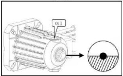
- Installing the suction hose and overflow hose.
Be sure to be equipped packing.
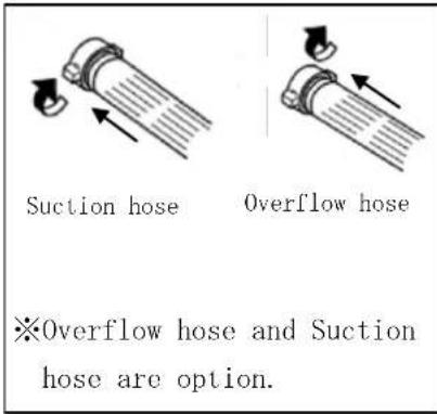
- Attaching the strainer for the hose coupling.

- Insert the suction hose and overflow hose into the chemical tank.

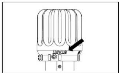
- Coincide knob of pressure regulator with START.

natural_image
Technical line drawing of a mechanical component with no visible text or symbols- Close the valve.

natural_image
Technical line drawing of a mechanical valve assembly with an arrow indicating direction (no text or symbols)- Starting

- Pressure regulation.

- Spraying

- Stopping spraying

natural_image
Technical line drawing of a device with a labeled component and directional arrows indicating motion (no text or symbols present)- Wash up with the clean water after spraying.
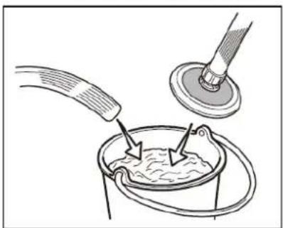
natural_image
Illustration of a mechanical or fluidic process with a tool and pipe pouring liquid into a container (no text or symbols)- Running the Power Sprayer.
Running the Power Sprayer.
- Continue to run the sprayer for one minute after raising the strainer.

natural_image
Illustration of a medical procedure showing a tool interacting with a cup and another cup, no text or symbols present.- Caution !!

- Stopping
Stopping the engine.
- Detach the suction hose and overflow hose.

- Resume knob to START position.
natural_image
Technical line drawing of a heat exchanger or cooling unit with no visible text or symbolsProtection from freezing.
Water should be completely drained during winter storage to prevent freezing.
The operation is per formed according to items from 11 to 18 in the operation procedure.
Inspection and adjustment
Discharge valve and its vicinity.
Inspect discharge valve and valve seat for wearing degree over their contact surface. Replace worn or spoiled ones, if any.

Piston and its vicinity.
Inspect parts as exploded for damage wear break, etc. Lubricate mobile oil over piston packing when assembled.

Replacement of Crankcase oil.
Replace at 50 hours operation after initial operation.

Precautions
When hoses are vibrating themselves...
Thank you very much for your purchase this time. Needless to say, no matter how excellent the quality of the product may be it won't display its maximum potential performance unless operated properly.
Read this Owner's/Operator's Manual repeatedly prior to operation in order to make the best use of the product.
Power sprayers are for agricultural or irrigation uses and not for industrial use.
Therefore, do not use chemicals, seawater, hot water, etc.
When agrichemicals are used, read and follow the Owner's/Operator's Manual for chemicals.
You had better go and ask our dealer nearby or shop you purchased from for further information and questions you have on the product.
When pump fails to suck liquid.
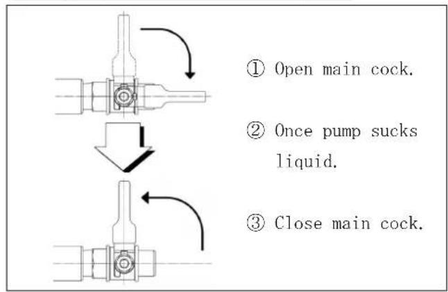
flowchart
graph TD
    A["① Open main cock."] --> B["② Once pump sucks liquid."]
    B --> C["③ Close main cock."]
Hose vibration occurs when air is released out of air-chamber.
It will stop if you let air send forth as following procedural.
①
②Release pressure

natural_image
Technical line drawing of a mechanical valve assembly with no visible text or symbols
natural_image
Diagram of a heat exchanger or cooling unit with no visible text or symbols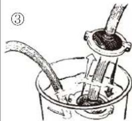
natural_image
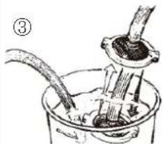
Diagram of a mechanical assembly with tubing and a central component (no text or labels)Lift suction strainer once to let it suck air for about 10 seconds and plunge it into water again.
④

natural_image
Mechanical component diagram showing a valve assembly with a curved arrow indicating direction (no text or symbols)⑤
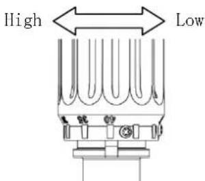
When pressure fails to get accumulated…
●Inspect pressure regulating valve for wear.

●Replace wrong nozzle for proper one.
When nozzle orifice is big.... Make orifice smaller

natural_image
Two identical line drawings of a conical object with a circular top and flange (no text or symbols)When spray is voluminous .... Make spray less voluminous.

natural_image
Technical line drawings of two electrical connectors (no text or symbols)Choose right nozzle so that its spray volum fails on about 80% (but not more than 80%) of suction volume.
natural_image
Technical line drawing of a heat exchanger or cooling unit with a black arrow pointing to the outlet (no text or symbols present)- Cerrar la válvula.

natural_image
Technical line drawing of a mechanical valve assembly with an arrow indicating direction (no text or symbols)- Arranque
Arrancar el motor.
natural_image
Illustration of a bucket being inserted into a container with a tool, showing fluid flow (no text or symbols)natural_image
Illustration of a medical procedure showing a tool interacting with a patient's mouth and cup (no text or symbols present)- ¡Cuidado!

natural_image
Technical line drawing of a heat exchanger or cooling unit with a black arrow pointing to the outlet (no text or symbols present)natural_image
Pure mechanical component diagram without any text, numbers, or symbols②Librar la presión.

natural_image
Illustration of a mechanical device being inserted into a container with a tool (no text or symbols visible)natural_image
Mechanical component diagram showing a valve assembly with a curved arrow indicating direction (no text or symbols)⑤
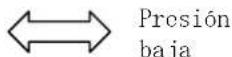
Alta presión

natural_image
Pure technical line drawing of a mechanical component with no text or symbolsnatural_image
Two identical line drawings of a conical device with a bulb-like top (no text or symbols)natural_image
Technical line drawings of two electrical connectors (no text or symbols)Brand : Maruyama
Model : MSD51
Category : Pump