MUSE 218 SND - Subwoofer FBT - Free user manual and instructions
Find the device manual for free MUSE 218 SND FBT in PDF.

| Brand | FBT |
| Model | MUSE 218 SND |
| Product Type | Powered Subwoofer |
| Driver Configuration | Dual 18" (460 mm) woofers |
| Frequency Response | 30 Hz – 200 Hz (-6 dB) |
| Maximum SPL | 139 dB peak |
| Amplifier Power | 2000 W RMS (Class D) |
| Input Impedance | 20 kΩ (balanced) |
| Input Connectors | XLR / 1/4" combo, Neutrik speakON |
| Output Connectors | XLR Link, speakON Link |
| DSP Processing | 24-bit / 48 kHz, presets and EQ |
| Enclosure Type | Bass reflex with front firing ports |
| Dimensions (W x H x D) | 600 mm x 1000 mm x 600 mm (23.6" x 39.4" x 23.6") |
| Weight | 82 kg (180.8 lbs) |
| Power Supply | 100-240 V AC, 50/60 Hz (auto-switching) |
| Power Consumption | 1000 W typical, 2200 W max |
| Cooling | Variable speed fan, rear exhaust |
| Maintenance | Clean with a soft dry cloth; check all connections periodically |
| Safety Features | Thermal and overcurrent protection, limiter, clip detection |
| Spare Parts & Repairability | Contact FBT authorized service center for genuine parts |
Frequently Asked Questions - MUSE 218 SND FBT
User questions about MUSE 218 SND FBT
0 question about this device. Answer the ones you know or ask your own.
Ask a new question about this device
Download the instructions for your Subwoofer in PDF format for free! Find your manual MUSE 218 SND - FBT and take your electronic device back in hand. On this page are published all the documents necessary for the use of your device. MUSE 218 SND by FBT.
USER MANUAL MUSE 218 SND FBT
natural_image
Black rectangular electronic device with mesh grille and small square button (no visible text or symbols)MUSE
218SND / 218SN / 218S / 218SA
AVVERTENZE......4
CARATTERISTICHE GENERALI 5
Descrizione 5
Specifiche....5
DIMENSIONI 6
PANNELLO & INGRESSI 7
Muse 218SND / 218SN....7
Muse 218S....7
Muse 218SA....8
Procedura upgrade SN / SND 13
Infinito system management suite 14
natural_image
Diagram of four car seats arranged in a layout with a 740mm dimension label (no text or symbols on the diagram itself)
natural_image
Top-down schematic of a rectangular frame with a central rectangle and multiple small dots, no text or symbols present.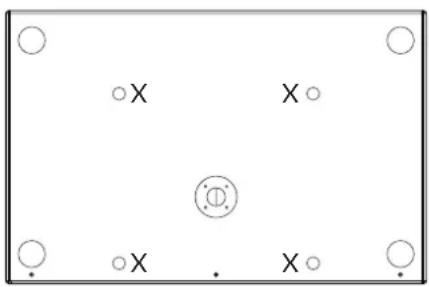
natural_image
Simple diagram with four circles and a central circle, no text or symbols present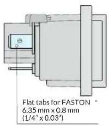
CONNESSIONE XLR
Disponibile sui modelli MUSE 218SND / 218SN / 218SA
INFINITO SYSTEM MANAGEMENT SUITE
natural_image
Isometric technical drawing of a rectangular frame with internal cutouts and dimension lines (no text or symbols)KBW-10045
Kit 4 ruote 100mm ø
MS-C218
Nylon cover per MUSE 218
MS-CH218 Nylon cover per MUSE 218 con ruote

natural_image
Simple line drawing of a 3D rectangular box with a square cutout on top (no text or symbols)MS-T218
Carrello trasporto
per 2 MUSE 218
natural_image
Line drawing of a four-legged flatbed cart with wheels, no text or symbols presentPower supply 100/120V....29
INPUTS & OUTPUTS....30
Xlr connection....30
Ethernet connection 30
Speakon 30
CONNECTIONS....31
NETWORKING....33
Networking of speakers.... 33
LN / LND upgrade procedure 33
CONTROLS & FUNCTIONS....34
Infinito system management suite 34
Interface Description....34
Main menù....36
ACCESSORIES....39
INSTALLATION 40
Cardioid configurations 40
TECHNICAL SPECIFICATION....41

GENERAL INFORMATIONS
MUSE 218SND / 218SN / 218S / 218SA Manual
Version: 1.1 ita, en - 11/2021 Code: 44814
Keep this document in a safe place so that it is available for future reference.
We recommend you to regularly check the FBT website for the latest version of this document.
When reselling this product hand over this document to the new owner.
FBT Elettronica SpA - 62019 Recanati (Italy)
www.fbt.it - info@fbt.itwww.fbt.it - info@fbt.it
- Read these instructions.
- Keep these instructions.
- Heed all warnings.
- Follow all instructions.
- Do not use this apparatus near water.
- Clean only with dry cloth.
- Do not block any ventilation openings. Install in accordance with the manufacturer's instructions.
- Do not install near any heat sources, such as radiators, heat registers, stoves or other apparatus (including amplifiers) that produce heat.
- Do not defeat the safety purpose of the polarized or grounding-type plug. A polarized plug has two blades with one wider than the other. A grounding type plug has two blades and a third grounding prong. The wide blade or the third prong are provided far your safety. If the provided plug does not fit into your outlet, consult an electrician fr replacement of the obsolete outlet.
- Protect the power card from being walked on or pinched particularly at plugs, convenience receptacles, and the point where they exit from the apparatus.
- Only use attachments accessories specified by the manufacturer
- Use only with the cart, stand, tripod, bracket, or table specified by the manufacturer or sold with the apparatus. When a cart is used, use caution when moving the cart/apparatus combination to avoid injury from tip-over.
- Unplug this apparatus during lightning storms or when unused far long periods of time.
- Refer alf servicing to qualified service personnel. Servicing is required when the apparatus has been damaged in any way, such as power-supply card or plug is damaged, liquid has been spilled or objects have fallen into the apparatus, the apparatus has been exposed to rain or moisture, does not operate normally, or has been dropped.

WARNING
RISK OF ELECTRIC SHOCK DO NOT OPEN

TO REDUCE THE RISK OF ELECTRIC SHOCK DO NOT REMOVE COVER (OR BACK) NO USER SERVICEABLE PARTS INSIDE REFER SERVICING TO QUALIFIED SERVICE PERSONNEL. TO REDUCE THE RISK OF FIRE OR ELECTRIC SHOCK DO NOT EXPOSE THIS EQUIPMENT TO RAIN OR MOISTURE'.
THE DEVICE MUST BE CONNECTED TO THE MAINS THROUGH A POWER OUTLET WITH A PROTECTIVE EARTH CONNECTION.

WARNING: where affixed on the equipment or package, the barred waste bin sign indicates that the product must be separated from other waste at the end of its working life for disposal. At the end of use, the user must deliver the product to a suitable recycling centre or return it to the dealer when
purchasing a new product. Adequate disposal of the decommissioned equipment for recycling, treatment and environmentally compatible disposal contributes in preventing potentially negative effects on the environment and health and promotes the reuse and/or recycling of equipment materials. Abusive product disposal by the user is punishable by law with administrative sanctions.
All informations included in this operating manual have been scrupulously controlled; however FBT is not responsible for eventual mistakes. FBT Elettronica SpA has the right to amend products and specifications without notice.

Never use the handles, brackets or other elements of the module to directly suspend the modules or the system. In case of outdoor use it is always advisable to anchor the system to prevent any oscillations due to wind or atmospheric agents.
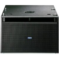
DESCRIPTION
MUSE 218SND is a direct radiation ground subwoofer, has two B&C 460mm long excursion speakers with 100mm voice coil and 4000W class D amplification, capable of 148.5dB SPL. The bass-reflex cabinet offers substantial energy up to 30Hz and is ideal for extending and reinforcing the low frequencies of the MUSE 210LND line array in ground-stack configuration.
It has presets to create various configurations with cardioid directivity, where some subwoofers face rearwards from the audience to acoustically cancel the sound pressure behind the cluster, obtaining a reduction of the SPL on the back by over 15dB.
The enclosure, optimized with BEM-type acoustic simulations to reduce resonance and turbulence of the ducts, is built with 18mm birch plywood with six handles and scratch-resistant paint. Reinforced front mesh with protective fabric and provision for optional four swivel-mount 4" (100mm) casters in the rear panel.
The summit of the entire project is the new 4000W amplification module with built-in TCP/IP network interface. Based on AES70 standard (OCA Alliance), it communicates with FBT's "INFINITO management suite" remote control software and receives 24bit 48-96Khz digital audio streaming from all devices compatible with "DANTE" standard. INFINITO is a real revolution in the FBT world that enhance the user experience in a new level of performance and simplicity! It's a software platform totally developed in house by FBT R&D team that offers real time monitoring of the internal sensors and status of connected devices, fast IN/OUT Vu-meters, controls of all the parameters, group management, warnings readout. The MUSE 218SND is equipped with intelligent forced ventilation and OLED display with encoder for parameter setting. A high-brightness blue front LED allows remote identification of the device also in daylight.
MUSE 218S: passive version. Nominal impedance 4Ohm. No crossover and internal protection inside the cabinet, it is necessary to use a processed amplifier or a digital processor with presets approved by FBT to equalize and protect the speaker from thermal overload and excessive excursion. Recommended amplifier power 4000W / 4Ohm.
MUSE 218SA: identical to the MUSE218SN / SND model except the lack of the network interface and display, it is not possible to control and monitor the speaker remotely. There are manual controls for settings on the back plate of the speaker.
SPECIFICATIONS
• Ground stack direct load subwoofer
- Very large area reflex port to ensure no power compression and very low port turbulence
- Double 18" (460mm) B&C very high excursion woofer with 4" (100mm) voice coil
• Frequency Response from 30Hz @-6dB
- Class D amplifier delivering 4000W RMS with switch mode power supply
• Network interface TCP/IP - AES70 compatible
- EtherCon RJ45 input and output for daisy-chain
- OLED DISPLAY and ENCODER with PUSH for easy onboard control
• DANTE audio streaming with 24bit at 48-96KHz on TCP/IP network
- 0.7" (18mm) birch plywood enclosure, scratch resistant black paint, 6 handles and heavy duty metal grille with synthetic protection cloth
• M20 top mount stand socket
- Optional 4 swivel-mount 4" (100mm) casters
- Low frequency extension cabinet for the MUSE 210LND line array for ground stacked configurations
MUSE 218SND / 218SN / 218S / 218SA
natural_image
Top-down diagram of four car seats arranged in a row, with no text or symbols present.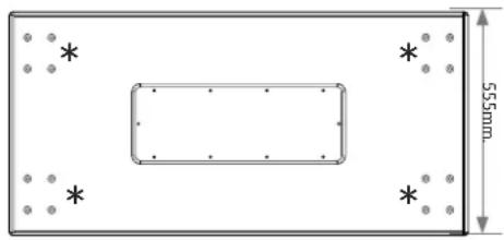
natural_image
Pure technical diagram of a rectangular layout with a central rectangle and marked points, no text or symbols present.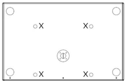
natural_image
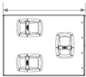
Simple diagram with circles and a central circle, no text or symbols present* WHEEL ARRANGEMENT
X MSF-210 ARRANGEMENT
MUSE 218SND / 218SN

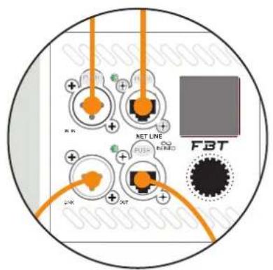
- XLR input
- Xlr link output
- Port compatible with EtherCON/RJ45 connectors used for Ethernet network input for remote control and monitoring via INFINITO MANAGEMENT SOFTWARE
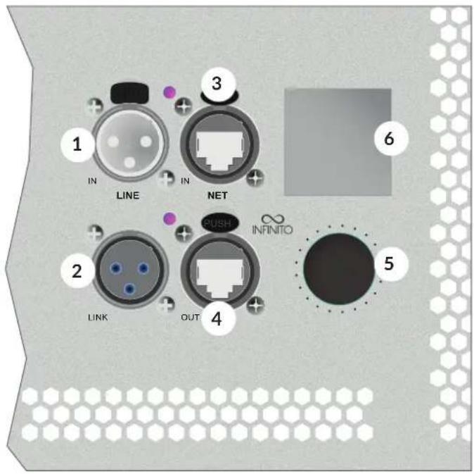
- Port compatible with etherCON/RJ45 connectors used for the daisy chain output of the INFINITO SOFTWARE MANAGEMENT remote control and monitoring Ethernet network
- General digital volume to control the level of signal. Press to enter the DSP menu and turn the knob to identify and select the parameters
- Displaying of menus and DSP settings
MUSE 218S

- Speakon connectors are connected in parallel mode. One connector can be used to connect the box to the output of a power amplifier, the other to connect to a second box.
MUSE 218SA
PRESET
ORIGINAL: corresponds to the typical FBT sound. It is the default general purpose preset and is thus fit for the majority of applications.
DEEP: this preset extends and emphasizes the low range of the subwoofer, for a very deep and soft sound suitable for high quality and medium energy applications, such as acoustic music, jazz, etc.
PUNCH: the sound of the sub becomes drier, reduced low frequency extension but more energy concentrated in the 80-120Hz range. Suitable for rock music and high SPL applications.
INFRA: the filter is set to a lower frequency with respect to the other presets, thus only very low frequencies are reproduced. Use this preset in systems with multiple subwoofers playing different frequency ranges. For subwoofers combined with the MUSE 218SA model, select the preset "XXXXX WITH INFRA".
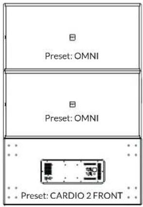
Cardioid rear
ORIGINAL 1 FRONT: preset to be used in systems with two subwoofers; select the ORIGINAL (1) preset on the speaker oriented toward the audience. (pic.1)
ORIGINAL 2 FRONT: preset to be used in systems with three subwoofers; select the ORIGINAL (1) preset on the two speakers oriented toward the audience. (pic.2)
INFRA 1 FRONT: preset to be used in systems with two subwoofers; select the INFRA (1) preset on the speaker oriented toward the audience. (pic.1)
INFRA 2 FRONT: preset to be used in systems with three subwoofers; select the INFRA (1) preset on the two speakers oriented toward the audience. (pic.2)
CONTROLS & FUNCTIONS
PRT / LMT: if this led light up there is a system malfunction due to an internal amplifier failure or to the intervention of current limiting circuits against thermal overload.
LED STATUS:
• VERDE: ON, system is in operating mode.
- YELLOW: STANDBY, in the absence of an input signal, after 30 minutes the amplifier goes into low power consumption mode. As soon as the signal exceeds the detection threshold, it returns to normal mode in less than 1 second.
- RED: FAN ERROR: signals an anomaly state of the fan that does not allow the amplifier to cool adequately. Check if the fan is free to spin, the fan may need to be replaced.
PHASE: the Phase control allows to optimize phase alignment, i.e. to obtain a uniform frequency response in the crossover area between the sub and the satellite. When it is set at "0°" the sound emission is in phase with the input signal; when it is set at "180°" the sound emission is in counterphase with the input signal; thanks to this control subwoofer adjustment will be even more flexible with a consequent performance optimization.
LEV: adjusts the signal general level.
PRESET: select 8 preset each of whom corresponds to a specific speaker equalization according to user's personal preferences and to the acoustics of the listening area.
DELAY: contral of a digital Delay line acting on the input signal; in this way it is possible to make up for the vertical misalignment of sub and satellite; the Delay is expressed in meters and goes from "O" to "3,5"mt.
IN / LINK: balanced input/output socket; "IN" allows to connect a preamplified signal such as that coming, for instance, from mixer output; "LINK" allows to connect multiple speakers to the same signal.
PIC.1
PIC.2
POWER SUPPLY 220 / 240V
For power supply MUSE 218SND / SN / SA models features a Neutrik PowerCon cable duplex with input and output.
CAUTION: never replace the plug of the power cord supplied since the power cord can only support maximum current of 16A.
POWER SUPPLY 100/120V
If the total current demand does not exceed 15A use the power cable supplied. If the total current demand is between 15A and 20A use the power cable AWG12SJTVW1 with plug rated current equal or greater than 30A.
THE CABLE AND THE PLUG MUST HOLD THE "UL" OR "CSA" CERTIFICATION
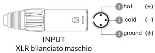
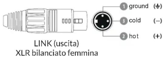
XLR CONNECTION
Available on MUSE 218SND / 218SN / 218SA models
The XLR connection is a type of balanced connection that allows the connection of devices over long distances without loss of quality due to the background noise detected.
This is made possible by the presence, as well as by the mass (pin 1), of two cables: a signal cable (pin 2) and a 180^ dephased signal cable (pin 3); at the opposite end of the signal source, on both these cables, in addition to the actual signal, the same quantity and type of background noise possibly detected along the path or inevitably produced by the cables (not the one for thermal agitation) will be present in phase. The signal will then be taken from the two cables by difference: in this way the useful part will be double amplitude while the noise detected or produced along the path, being present in phase on both cables, will be cancelled by the difference operation. In the three-pin version it is normally used for the termination of balanced audio lines but it is often also used for unbalanced signals creating a short circuit between the mass and the cold pin. The EIA RS-297-A standard requires that the three-pin XLR connectors for balanced audio are wired as shown in fig.
ETHERNET CONNECTION
Available on MUSE 218SND / 218SN models
Neutrik etherCON® connectors provide solutions for data transfer and more in harsh and demanding environments.
The etherCON® series is a robust and lockable RJ45 connector system optimized for professional audio, video and lightning network applications.
Thanks to the possibility of networking, the models of the Horizon series can be remotely controlled thanks to the INFINITO System Management Suite software.
It is advisable to use a cat.5e SF / UTP or higher class ethernet cable.
Support for DANTE Digital Studio Networking.


SPEAKON
MUSE218S is a 1-way system, that is, it needs to be driven by an amplification channel suitably processed with DSP parameters supplied by FBT. Improper use of the system with incorrect DSP settings can compromise the reliability of the transducers and exhibit suboptimal acoustic performance.
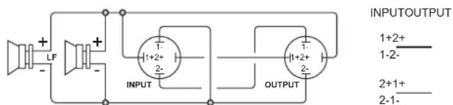
Internally there is no passive crossover, the speakers are connected directly to the SPEAKON connectors.
In the rear dashboard there are two NeutriK Speakon NL4M connectors, an input and an output. The internal configuration of the connection allows you to link two speakers with a 4-wire cable and drive them each with a dedicated amplification channel (see the section dedicated to the LINK below).
LINKS OF TWO OR MORE SPEAKERS
Attention! In this configuration it is necessary to use a 4-wire SPEAKON cable between the amplifier and the first speaker! Connect amplifier output channel 1 to terminals 1+ / 1- and channel 2 to terminals 2+ / 2- of the SPEAKON INPUT. Channel 1 is used to drive the speakers of the first connected speaker, while channel 2 is relaunched on terminals 1+ / 1- of the output SPEAKON which will be connected to the input of the second speaker with a normal two-pole speakon cable.
In the case of LINK of 4 SPEAKERS it is necessary to use a 4-pole SPEAKON cable also for the LINKS and consider that SPEAKER number 1 and 3 will be connected in parallel as well as speakers number 2 and 4. The impedance seen by the amplifier is halved, it will therefore be necessary to choose amplifiers capable of driving the impedance resulting from the parallel of the connected speakers.
The section of the SPEAKON cable must be suitable for the current supplied to the speakers. We generally recommend using the following sections:
- 2.5mm ^2 length up to 20mt
- 4mm ^2 over 20 mt
| LF+AMP CH1 | LF-AMP CH1 | LF+(linked cabinet)AMP CH2 | LF-(linked cabinet)AMP CH2 | |
| SPEAKONNL4MINPUT | 1+1-2+2- | |||
| SPEAKONNL4MOUTPUT/LINK | 2+2-1+1- | |||
flowchart
graph TD
    A["XLR INPUT"] --> B["FAT MUSE 218SND"]
    C["NETWORK INPUT"] --> D["MUSE 218SND @Dante™"]
    E["FAT MUSE 218SND"] --> F["MUSE 218SND @Dante™"]
    G["FAT MUSE 218SND"] --> H["MUSE 218SND @Dante™"]
    I["FAT MUSE 218SND"] --> J["MUSE 218SND @Dante™"]
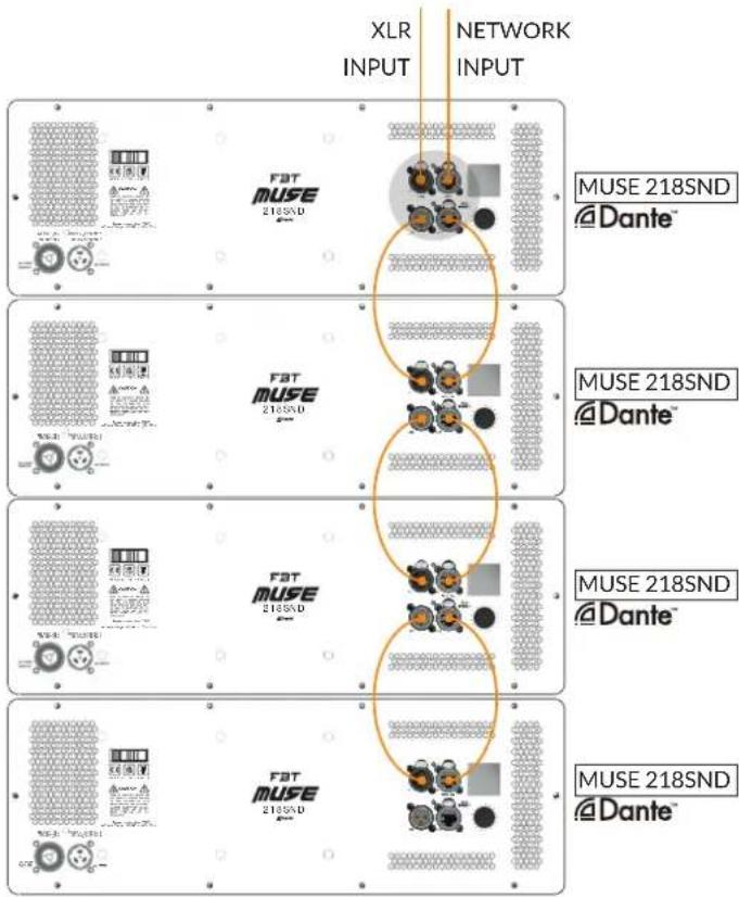
EX. CONFIG. 1
The example configuration with no.4 MUSE 218SND modules connected to each other allows:
• Dante only input (XLR links are required)
- Analog only input
• Dante input with analog backup
• Dante input with analog link (not recommended)
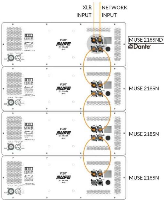
EX. CONFIG. 2
The configuration in the example with no.1 MUSE 218SND module and no.3 MUSE 218SN modules connected to each other allows:
- Dante input on the MUSE 218SND module and analog link on the MUSE 218SN modules, analog backup possible
- Analog only input

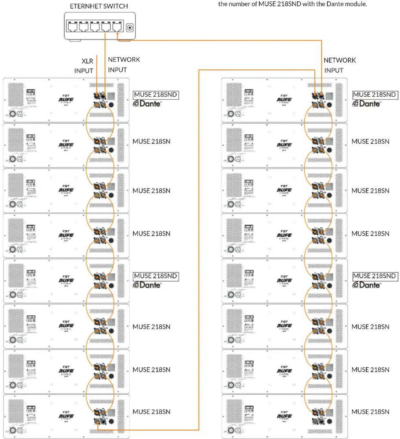
EX. CONFIG.3
Mixed Dante configuration + analog link with up to 8 modules connected to each other in daisy chain
- Ideally do not connect more than 8 daisy chain modules over a network. If it is necessary to guarantee the "hardware bypass" operation on the network in the event of breakage of a device, the maximum number of modules that can be connected in a daisy chain falls to 4 (in this case, in fact, the breakage of a single device does not compromise the network connection of the others connected in cascade to it)
- With the suggested configuration you have the best compromise in terms of safety in case of failure of one or more speakers, minimizing the number of MUSE 218SND with the Dante module.
flowchart
graph TD
    A["ETERNHET SWITCH"] --> B["XLR INPUT"]
    A --> C["NETWORK INPUT"]
    A --> D["the number of MUSE 218SND with the Dante module."]
    D --> E["MUSE 218SND @Dante™"]
    D --> F["MUSE 218SN"]
    D --> G["MUSE 218SN"]
    D --> H["MUSE 218SN"]
    D --> I["MUSE 218SN"]
    D --> J["MUSE 218SND @Dante™"]
    D --> K["MUSE 218SN"]
    D --> L["MUSE 218SN"]
    D --> M["MUSE 218SN"]
NETWORKING OF SPEAKERS
All the speakers are equipped with a dual Ethernet port for connection to INFINITO MANAGEMENT SOFTWARE and a high-brightness front BLUE LED that allows you to physically identify the speaker when connected to the network and remotely controlled.
With the WINK function present on the INFINITO software, the LED flashes allowing the association between the virtual device in the PC workspace and the physical device.
There are 3 ways to connect to the network:
- Star connection: it is possible to connect each speaker individually to the network by connecting the NET IN port directly to the dedicated switch. This type of connection is the simplest from the point of view of the complexity of the network itself, as it involves the least number of HOPS (switch jumps that a packet must make from the PC to the target device). This type requires a large number of network ports on switches and also very long wiring to reach the farthest devices (for example, the speakers at the end of a line array). From a safety point of view, a faulty network cable results in a loss of control on only one device
- Daisy Chain connection: it is possible to connect a whole series of speakers close together (e.g. Line array) to a single switch network port, using both available NET IN and NET OUT connections. Simply connect the switch port to the first speaker through the NET IN port, then wire the NET OUT with the NET IN of the second speaker, and so on to the last in the series. This type of connection simplifies the physical operation of wiring, resulting in being able to use shorter cables (similar to the set-up for the analog signal link), but complicates the structure of the network and increases the number of hops (and therefore the arrival time) of network packets especially intended for devices at the bottom of the chain. Any interruption of a network cable results in the loss of control on all devices located downstream of the breakage
- Mixed connection: it is possible to use a mixed structure, dividing each cluster into subgroups of devices. The first device in each group is connected via NET IN to the switch, then using the daisy chain structure the other elements are connected. In this case, an intermediate complexity network is obtained both from the physical point of view of the wiring and from that of the operation of the network itself. The interruption of a network cable causes the loss of a small number of devices, depending on how many devices each group contains and the level at which the breakage occurred within the group.
In the case of a large number of devices (for example, very large line arrays) it is advisable to use a mixed connection, dedicating a switch for each line array and dividing it into groups of up to 8 devices, connected to each other in a daisy chain.
Each device is equipped with a hardware bypass device of the network that, in the event of a serious malfunction that involves the shutdown of the internal logic, short-circuits the NET IN and NET OUT ports; in this way, all the devices located downstream of the breakage will still be controllable through INFINITY. The system is able to compensate for the breakage of 3 consecutive devices within each single daisy chain.
In order to ensure the correct operation of the system it is advisable to use cables of category CAT5e or higher.
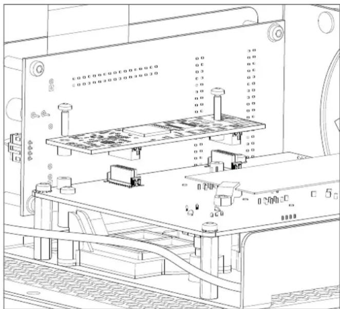
SN / SND UPGRADE PROCEDURE
Optional DANTE module installation (upgrade from SN / SND version)
- Remove the rear panel
- Refer to the figure to locate the position of the card and the correct orientation
- Lift the flat cable and gently press the card in alignment with the connectors so that the PCB touches the screw columns
- Screw in the two fixing screws supplied
- Reposition the rear panel
- When switched on, the system detects the new "SND" version which entails additional functions in the menu (related to DANTE). By connecting the device to the network, the INFINITO MANAGEMENT SUITE software detects the "SND" model
INFINITO SYSTEM MANAGEMENT SUITE
INFINITO is the new software platform for the remote control and monitoring of a new generation of FBT products that will expand over time (active speakers, amplifiers, DSP processors, etc...).
Based on standard 10/100 Ethernet infrastructure with TCP/IP protocol and compliant with the AES70 standard (OCA ALLIANCE), the software is used to control over 100 devices in the same network with automatic assignment of the IP address.
Features:
• Compatible with Windows 7, 8, 10
• Real-time monitoring of sensors, vu-meters, transducers, failure etc.
- Checking of all DSP parameters
- Intuitive graphical and Touch oriented interface
- Creation of ADVANCED and BASIC groups for extremely versatile and simple control of connected devices
- Instantly saving and calling up of SCENES (snapshots of the entire project)
- Comprehensive status information of connected devices (warning, info)
- SETUP, TUNING and SHOW operating modes with advanced safety system to switch between modes
- Possible OFFLINE, ONLINE and LIVE management of devices on the workspace
- Displaying of the details of the multilevel device in order to focus attention solely on the parameters of interest of the individual device
- Global MUTE
• Automatic firmware update of the connected devices
• Day or night selectable graphical interface
INTERACTION OF LOCAL DEVICE CONTROLS AND INFINITO SOFTWARE
The control and monitoring of the MUSE210LND can be performed either locally via display and knob, or remotely via Ethernet network and a PC with INFINITO FBT software suite installed.
In this case, when the ONLINE mode is activated on the software, the speaker switches to remote control mode: the display is locked and switched off and Infinito takes control of all the speaker variables. In this mode, by pressing the knob the display turns on and shows: "Controlled by INFINITO - Push to WINK".

Pressing the knob in the software turns on the box relating to the device, thus allowing the unique identification between the real and virtual device present in the workspace.
The remote mode, once activated, remains permanent even if the INFINITO software is closed, the network is disconnected and/or the network cable is disconnected, the speaker is switched off and on again; all the settings of the DSP inside the device remain those set via INFINITO.
To return to the local control mode via display, the network must be disconnected or the software must be in an OFFLINE state: in this case, the local display shows the message "Switch to local control? NO - YES".

Selecting YES activates the unlock procedure: "Push and hold for 3 seconds" appears on the display.

and after prolonged pressing, the display is once more active, re-enabling the local controls. After switching to the local (manual) control mode, the DSP settings made in the last manual session before connecting to INFINITO are restored.
However, it is always possible to switch to the settings set in the last INFINITO session, using the MEMORY menu, via the "RECALL" function, choosing the "INFINITO" memory location as described below.
MANAGEMENT OF MEMORY INSIDE THE DEVICE:
There are 6 memory locations on the device where all the settings available on the device are saved:
- INFINITO: intended for the settings made by the software. This memory area saves the settings that are sent from the last INFINITO session. It cannot be deleted by user.
- SNAP1,2,3,4: these locations are free and available to the user who can save, recall and delete. They include all the settings that can be made locally through menus.
- DEFAULT: reserved for the settings of all parameters in the factory state. Useful for re-resetting of the device, restoring all the parameters to the initial state.


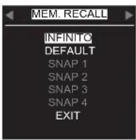


When the INFINITO -> MANUAL transition is made, the last manual settings that were set in the last manual session are loaded via the unlock procedure from the display.
When connecting INFINITO, when the "ONLINE" mode is connected, it is possible to give the "SYNC TO" command to send the software settings to the speaker, or "SYNC FROM" to restore the settings present in the "INFINITO" memory location of the device and transmit them to the software.
From the display menu it is possible to recall the settings of the last INFINITO session even if the device is not connected to INFINITO.
CAUTION: By means of INFINITO it is possible to control a number of parameters that cannot be managed with local control via display. Therefore these parameters, listed below, in the INFINITO -> Local transition are returned to the default conditions (unless it is decided to load the 'INFINITO' memory location via display):
- Fallback (DANTE on ANALOG): OFF
• Analog/Dante Trim: 0 dB
• Analog/Dante Delay: 0 ms - MuteAll, Mute: Unmuted
INTERFACE DESCRIPTION
The Home page of the display shows the essential information of the speake
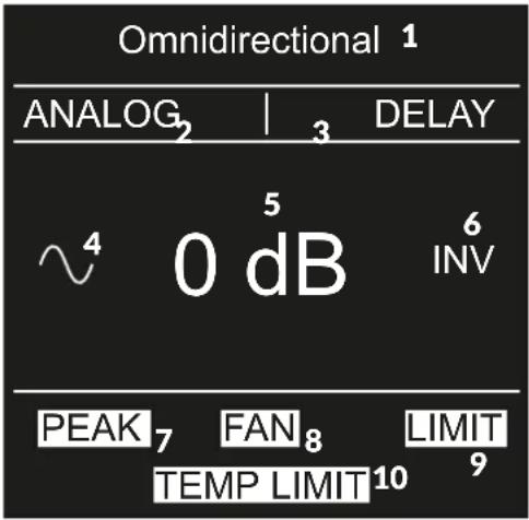
SETTING INDICATORS
- PRESET: setting of the configuration preset
- ANALOG/DANTE: incoming signal routing
- HFL: indicates that HF LEVEL gain is not zero
- DELAY: indicates the presence of delay applied to the input signal; by default the delay is 0ms and no indication is displayed
- SIGNAL PRESENCE: indicates that there is an incoming audio signal
- HIGH PASS FILTER: indicates the presence of a high pass filter set; by default it is set in bypass mode and no indication is displayed
- VOLUME: general system volume; it can vary from +6dB to MUTE with 1dB steps by turning on the encoder
PROTECTIVE INDICATORS
- PEAK: input stage saturation (ADC)
- FAN ERROR: reports a possible fan fault
- LIMIT: indicates the activation of the signal limiter to safeguard the transducers and to avoid distortion
- TEMP LIMIT: indicates the gradual reduction of the signal to avoid thermal protection
On the HOME screen, it is only possible to change the volume by turning the encoder; pressing it allows access to the menu.
FAULT INDICATORS
In the event of a malfunction, the display provides an indication of the possible cause, differentiating between thermal causes (e.g.: a fan malfunction prevents the amplifier from dissipating excess heat, leading the system to overheat), reported as TEMP PROTECTION ), or generic amplifier breakages reported as PROTECTION.


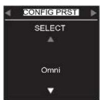
MAIN MENÙ
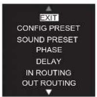


From the "HOME" screen, pressing the knob accesses the menu where all the controllable functions are listed, turning the knob scrolls the list vertically. Clicking on an item it is possible to access the relative setting and clicking on 'EXIT' leads to the horizontal menu where it is possible to navigate between the functions and viewing the current setting.
EXIT

To exit the menu and to return to the "HOME", scroll to the last item "EXIT" and click by pressing the knob, or keep it pressed for a few seconds from any point on the menu.
CONFIG. PRESET
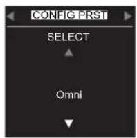
The correct selection of this parameter is very important because it allows you to set the type of acoustic dispersion (directionality) of the system between OMNIDIRECTIONAL and CARDIOID. CARDIOID directivity can only be obtained from the correct physical configuration of two or more subwoofers and from the correct CONFIG PRESET selected. Refer to the CARDIOID configuration section of the manual for details.
SOUND PRESET
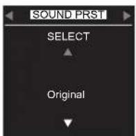
It allows you to choose between different types of system frequency responses to adapt the timbre to the music program or to the installation environment.
PHASE
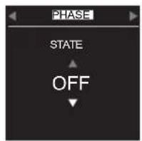
Enable or disable the phase inversion of the signal. It may be useful to invert the phase to ensure the correct acoustic sum between subwoofer and satellite. Generally for all FBT products it is not necessary to invert the phase to have a correct overall response of the system.
DELAY
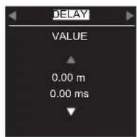
It regulates the time that must elapse between receiving of the incoming signal and the playback, expressed in ms and meters based on the estimated sound speed at 343m/s. Minimum pitch 0.03ms (1cm), maximum value 874ms (300m). Very useful to temporarily align the emissions of speakers located at different points.
IN ROUTING
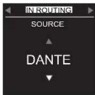
Choice of signal source between ANALOG (balanced XLR) and DANTE (multichannel audio over Ethernet network, LND model only with DANTE card installed).
OUT ROUTING

Choice of the signal present on the XLR OUT connector between ANALOG (direct link with XLR input) or DANTE (only if IN ROUTING on DANTE). The DANTE digital signal is internally converted into analog with a DAC of the highest quality and presented on XLR OUT (0dBFS=18dBu).
NOISE GATE
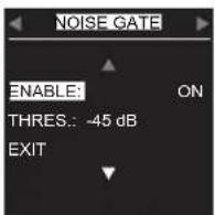
Enables and adjusts the threshold of the digital noise-gate algorithm that is used to attenuate the background noise produced by the amplification chain when there is no useful input signal.
DANTE
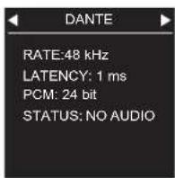
The parameters of the internal DANTE card are displayed. Through the AUDINATE DANTE CONTROLLER software it is possible to assign and control all DANTE devices in the network.(LND model only).
AUTO ST-BY
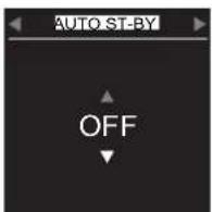
Enables or disables the automatic STANDBY function. In the absence of an input signal, after the default time, the speaker enters low power mode. The power section is turned off while the processor remains powered and connected to the Ethernet network. Reactivation occurs automatically when the signal exceeds a preset threshold.
SENSORS
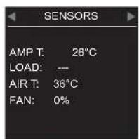
Access to the display of the parameters detected by the internal sensors such as temperature, supply voltage, inclination, fan status and transducer status. To exit, click anywhere or on "EXIT".
TEST
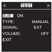
Enables the acoustic test of the transducers in MANUAL or AUTOMATIC mode. In manual you select the external or internal signal (pink noise). By raising the volume automatically, a test procedure starts with pink noise which cyclically enables or not the sound (ON-OFF).
MEMORY


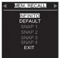


It is used to save and recall all the menu settings (snapshots) in four memory locations (SNAP1...4). In addition, a "DEFAULT" location with the factory parameters and an "INFINITO" with the settings made through the INFINITO suite software during the last session are always available for the RECALL.
Attention: the INFINITO location contains many more parameters than those that can be managed from the speaker display. It is useful to recall this location in order to restore the last session of INFINITO without having to reconnect the speaker to the network.
It is not possible to delete the "DEFAULT" and "INFINITO" locations using the "DELETE" function.
LOCK SCREEN
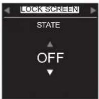
Used to block the menu from undesirable tampering, it presents the LITE and SECURE modes. To release the LITE mode, simply press and hold the knob for 5 seconds (instructions on the display). To release the SECURE mode it is necessary to press the knob 10 times in quick sequence (the instructions do not appear on the display).
CONTRAST
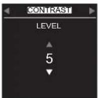
Adjusts the brightness of the display.
DISPLAY OFF
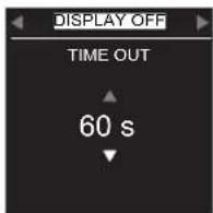
Selects the display power-on time for each action on the knob. It is not possible to leave the display always on. This is to avoid the degradation of performance over time. Each alert and action state on the knob causes the display to turn on automatically for the set time.
ROTATION
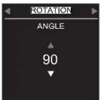
Depending on the horizontal or vertical installation of the speaker, the graphic orientation of the display is rotated manually (selecting the angle) or automatically using the internal inclination sensor.
FACTORY RESET

Reset of the entire processor that is used to set all the parameters to the initial default state.
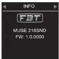
INFO
natural_image
Isometric technical drawing of a rectangular frame with internal cutouts and dimension lines (no text or symbols)KBW-10045
4 Wheels Kit with brake 100mm ø

MS-C218
Nylon cover for MUSE 218
MS-CH218
Nylon cover for MUSE 218 with wheels

natural_image
Simple line drawing of a 3D rectangular box with a square cutout on top (no text or symbols)MS-T218
Trolley for 2 MUSE 218

natural_image
Line drawing of a four-legged flatbed pallet with wheels, no text or symbols presentCARDIOID CONFIGURATIONS
Cardioid configurations are useful to cancel low frequencies from the stage and consequently to improve critical microphone recordings.
The cardioid configuration enables a cardioid distribution of the SPL from subwoofers, reducing rear sound pressure.
It is perfect when the energy of the low frequencies has to be attenuated, for example on the stage or in areas where it should be avoived due to noise pollution.
For this purpose a rea sub shall be employed every two front subs. The majority of the energy generated by the rear sub is used to cancel the energy of the other two subs in the front area is equal to +1dB approximately compared to a non cardioid configuration with two front subs only.
Obviously, this configuration is valid also with a FRONT sub and a REAR sub.

Horiz. f=40Hz
Horiz. f=80Hz, normed to 1
Horiz. f=130Hz, normed to 1
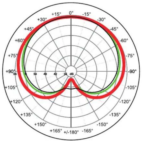
radar
| Angle | Red Line (dB) | Green Line (dB) | | ------ | ------------- | --------------- | | 0° | ~100 | ~95 | | -30° | ~98 | ~92 | | -60° | ~95 | ~88 | | -90° | ~90 | ~80 | | -120° | ~85 | ~75 | | -150° | ~80 | ~70 | | -180° | ~75 | ~65 | | -210° | ~70 | ~60 | | -240° | ~65 | ~55 | | -270° | ~60 | ~50 | | -300° | ~55 | ~45 | | -330° | ~50 | ~40 | | -360° | ~45 | ~35 |Ex. config.1
CONFIG PRESET
| Frequency response @ -6dB 30Hz preset | dependant 30Hz preset dependant 30Hz preset | dependant | |
| Sensitivity (@1W/1m) dB --- 103.5 | --- | ||
| SPL max. (cont / peak) | dB | 142.5 / 148.5 half-space | 142.5 / 148.5 half-space (Bi-Amp) |
| Dispersion | H x V | Omnidirectional | Omnidirectional |
| Recommended HP filter | --- 25Hz - 24dB/oct | --- | |
| Recommended external filter | --- FBT DSP processor | --- |
AMPLIFIER
| Built-in amplifier max. | W | 4000 | --- 4000 | |
| Built-in amplifier peak | W | 8000 | --- 8000 | |
| Recommended amplifier | W RMS | --- | 4000 | --- |
| Long Term Power | W | --- 2000 | --- | |
| Short Term Power (IEC 268-5) | W | --- | 8000 | --- |
| Input impedance | kOhm | 22 | --- | 22 |
| Nominal impedance | Ohm | --- 4 | --- |
INPUTS / OUTPUTS
| Power supply connectors | PowerCon IN/OUT | --- PowerCon IN/OUT | ||
| Input connectors | XLR IN / OUT | 2 x Speakon NL4M in & out | XLR IN / OUT | |
| Input / output NET | NET IN / NET OUT (EtherCon) | ---- |
POWER SUPPLY SPEC.
| AC Power requirements | W | 800 | --- 800 | |
| Power cord | ft. | 16.4 | --- 16.4 |
MECHANICAL SPEC.
| Material | wooden cabinet - black finish | wooden cabinet - black finish | wooden cabinet - black finish | |
| Handies | Integrated (3 x side) | Integrated (3 x side) | Integrated (3 x side) | |
| Net sizes (WxHxD) | inch | 44,88 x 28,13 x 21,85 | 44,88 x 28,13 x 21,85 | 44,88 x 28,13 x 21,85 |
| Transport dimensions (WxHxD) | inch | 47,24 x 31,49 x 28,74 | 47,24 x 31,49 x 28,74 | 47,24 x 31,49 x 28,74 |
| Net weight | lbs | 218,25 | 211,64 | 218,25 |
| Shipping weight | lbs | 238 with pallet | 231,48 with pallet | 238 with pallet |


FBT ELETTRONICA SPA
Via Paolo Soprani 1 - 62019 RECANATI - Italy
Tel. 071750591 - Fax. 071 7505920
email: info@fbt.it - www.fbt.it