
QSA 118S - Subwoofer FBT - Free user manual and instructions
Find the device manual for free QSA 118S FBT in PDF.


| Type | Active subwoofer |
| Driver Size | 18 inches |
| Amplifier Power | 1000 W RMS |
| Frequency Response | 40 Hz - 200 Hz |
| Maximum SPL | 130 dB |
| Impedance | 8 ohms |
| Dimensions (W x H x D) | 600 x 700 x 600 mm |
| Weight | 40 kg |
| Power Supply | AC 100-240 V, 50/60 Hz |
| Enclosure Type | Bass-reflex |
| Inputs | XLR, 1/4" jack, Speakon |
| Outputs | XLR link output |
| Phase Switch | 0°/180° |
| Crossover Frequency | 80 Hz - 120 Hz adjustable |
| Protection Features | Thermal, short circuit, limiter |
| Cooling | Convection cooling |
| Material | Plywood with polyurea coating |
| Grille | Steel grille with acoustic foam |
| Handles | Two side handles |
| Pole Mount | M20 threaded socket |
Frequently Asked Questions - QSA 118S FBT
User questions about QSA 118S FBT
0 question about this device. Answer the ones you know or ask your own.
Ask a new question about this device
Download the instructions for your Subwoofer in PDF format for free! Find your manual QSA 118S - FBT and take your electronic device back in hand. On this page are published all the documents necessary for the use of your device. QSA 118S by FBT.
USER MANUAL QSA 118S FBT
natural_image
Stacked black server racks with mesh patterns, no visible text or symbols

CONSTANT
CURVATURE
LINE ARRAY
QSA 112.0A
QSA 112.0
QSA 112A
QSA 112
QSA 118SA
QSA 118S
CE
| IMPORTANTI ISTRUZIONI DI SICUREZZA | 1 |
| ALIMENTAZIONE | 3-4-5-6 |
| CARATTERISTICHE | 7-9-11-12 |
| SPECIFICHE TECNICHE | 14 |
| CONFIGURAZIONI | 19-20 |
| PANNELLO CONNESSIONI QSA 112 / QSA 118S | 21 |
| SELETTORE X-OVER | 22 |
| HF LEV SELECTOR | 23 |
| PANNELLO CONNESSIONI QSA 112A / QSA 118SA | 24-25 |
| PRESET | 26 |
| IMPOSTAZIONI PRESET | 27 |
| INSTALLAZIONE | 31-32 |
| ACCESSORI | 33 |
| DIMENSIONI | 34 |
| DIAGRAMMI | 35 |
| GLOSSARIO | 36 |
| IMPORTANT SAFETY INSTRUCTIONS | 1 |
| POWER SUPPLY | 3-4-5-6 |
| KEY FEATURES | 7-9-11-12 |
| TECHNICAL SPECIFICATIONS | 15 |
| CONFIGURATIONS | 19-20 |
| CONNECTION PANEL QSA 112 / QSA 118S | 21 |
| X-OVER SELECTOR | 22 |
| HF LEV SELECTOR | 23 |
| CONNECTION PANEL QSA 112A / QSA 118SA | 24-25 |
| PRESET | 26 |
| PRESET SETTING | 28 |
| INSTALLATION | 31-32 |
| ACCESSORIES | 33 |
| DIMENSIONS | 34 |
| DIAGRAMS | 35 |
| GLOSSARY | 36 |
| INFORMATIONS DE SÉCURITÉ IMPORTANTES | 2 |
| ALIMENTATION | 3-4-5-6 |
| CARACTÉRISTIQUES | 8-10-11-13 |
| CARACTÉRISTIQUES TECHNIQUES | 16 |
| CONFIGURATIONS | 19-20 |
| PANNEAU CONNEXIONS QSA 112 / QSA 118S | 21 |
| SÉLECTEUR DE MODE X-OVER | 22 |
| HF LEV SELECTOR | 23 |
| PANNEAU CONNEXIONS QSA 112A / QSA 118SA | 24-25 |
| PRESET | 26 |
| PROGRAMMATION DES PRESET | 29 |
| INSTALLATION | 31-32 |
| ACCESSOIRES | 33 |
| DIMENSIONS | 34 |
| DIAGRAMS | 35 |
| GLOSSAIRE | 37 |
TO REDUCE THE RISK OF FIRE OR ELECTRIC SHOCK DO NOT EXPOSE THIS EQUIPMENT TO RAIN OR MOISTURE

WHERE MARKED, THIS SYMBOL INDICATES A DANGEROUS NON-ISOLATED VOLTAGE INSIDE THE LOUDSPEAKER: SUCH VOLTAGE COULD BE SUFFICIENT TO RESULT IN THE RISK OF ELECTRIC SHOCK.

WHERE MARKED, THIS SYMBOL INDICATES IMPORTANT USAGE AND MAINTENANCE INSTRUCTIONS IN THE ENCLOSED DOCUMENTS. PLEASE REFER TO THE MANUAL.
IMPORTANT SAFETY INSTRUCTIONS
1) Read these instructions
2) Keep these instructions
3) Heed all warnings
4) Follow all instructions
5) Do not use this apparatus near water
6) Clean only with dry cloth
7) Do not block any ventilation openings. Install in accordance with the manufacturer's instructions.
8) Do not install near any heat sources, such as radiators, heat registers, stoves or other apparatus (including amplifiers) that produce heat
9) Do not defeat the safety purpose of the polarized or grounding-type plug. A polarized plug has two blades with one wider than the other. A grounding type plug has two blades and a third grounding prong. The wide blade or the third prong are provided for your safety. If the provided plug does not fit into your outlet, consult an electrician for replacement of the obsolete outlet.
10) Protect the power cord from being walked on or pinched particularly at plugs, convenience receptacles, and the point where they exit from the apparatus.
11) Only use attachments/accessories specified by the manufacturer.
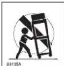
12) Use only with the cart, stand, tripod, bracket, or table specified by the manufacturer or sold with the apparatus. When a cart is used, use caution when moving the cart/apparatus combination to avoid injury from tip-over.
13) Unplug this apparatus during lightning storms or when unused for long periods of time.
14) Refer all servicing to qualified service personnel.
Servicing is required when the apparatus has been damaged in any way, such as power-supply cord or plug is damaged, liquid has been spilled or objects have fallen into the apparatus, the apparatus has been exposed to rain or moisture, does not operate normally, or has been dropped.
THE DEVICE MUST BE CONNECTED TO THE MAINS THROUGH A POWER OUTLET WITH A PROTECTIVE EARTH CONNECTION.
This device features a power outlet; install the device so that the outlet for the power cord is easily accessible.
PRECAUTIONS
☐ For proper air ventilation please make sure to leave sufficient clearance (min 11 inc.) on all sides of the device.
☐ Please do not cover the ventilation slots with papers, table cloths, curtains, etc. in order not to prevent ventilation of the device.
☐ Please do not place any naked flame source, such as lighted candles, on the device.
☐ Please keep the device away from water springs and splashes and please do not place any objects containing liquids, such as vases, on the device.
☐ CAUTION: To avoid the risk of injuries please secure the device to the wall following the enclosed instructions.
POUR ÉVITER LE RISQUE DE CHOC ÉLECTRIQUE NE PAS OUVRIR LE COUVERCLE NE PAS UTILISER D'OUTILS MÉCANIQUES À L'INTÉRIEUR CONTACTER UN CENTRE D'ASSISTANCE QUALIFIÉ
POUR ÉVITER LE RISQUE D'INCENDIE OU DE CHOC ÉLECTRIQUE NE PAS EXPOSER L'APPAREILLAGE À LA PLUIE OU À L'HUMIDIT

CE SYMBOLE PRÉVIENT, LÀ OÙ IL APPARAÎT, DE LA PRÉSENCE D'UNE TENSION DANGEREUSE NON ISOLÉE À L'INTÉRIEUR DE LA CAISSE : LE VOLTAGE PEUT ÊTRE SUFFISANT POUR REPRÉSENTER UN RISQUE DE DÉCHARGES ÉLECTRIQUES.

CE SYMBOLE PRÉVIENT, LÀ OÙ IL APPARAÎT, DE LA PRÉSENCE D'IMPORTANTES NOTICES DE MODE D'EMPLOI ET CONCERNANT L'ENTRETIEN DANS LA DOCUMENTATION JOINTE. VEUILLEZ CONSULTER LE MODE D'EMPLOI.
INFORMATIONS DE SÉCURITÉ IMPORTANTES
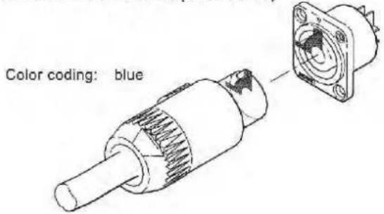
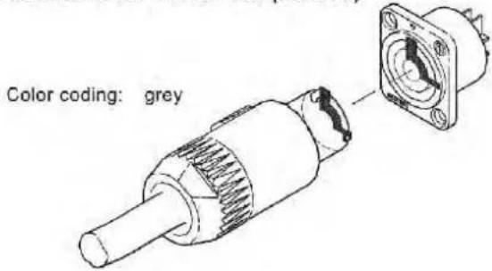
For its power supply, the whole QUBE series features two NEUTRIK powercon three-pole outlets with locking connectors. Use the grey outlet for connecting several speakers with one another, and the blue one for supplying power to the system through the connector supplied.
CAUTION: the cable supplied can be used alone, and only if the total current absorption is lower than 16A.
CAUTION: never replace the plug of the power cord supplied since the power cord can only support a maximum current of 16A.
CAUTION: if the absorbed current exceeds 16A and is lower than 20A, a power cord has to be manufactured by specialized staff using a H05VV-F cable with 2.5 sq. mm section and plug with rated current > = 20A , where 20A is the maximum rated current of the Powercon connector.
- The power cord has to be assembled by specialized staff complying with national plant-engineering regulations.
- Protect the mains cable when it is not used.
- In case of "chain connection", connect the cable to the grey outlet of the first speaker and to the blue outlet of the second one, and so on, making sure the maximum current indicated on the "AC LOOP OUTPUT" is not exceeded.
For its power supply the whole QUBE series features two NEUTRIK Powercon three-pole outlets with locking connectors. Use the grey outlet for connecting several speakers with one another, and the blue one for supplying power to the system through the connector supplied.
CAUTION: if the total current demand does not exceed 12A, use the power cable supplied.
If the total current demand is between 12A and 18A, use the power cable "AWG 14 SJT VW1" with plug rated current equal to 24A or lower.
THE CABLE AND THE PLUG MUST HOLD THE UL OR CSA CERTIFICATION.
- The power cord has to be assembled by specialized staff complying with national plant-engineering regulations.
- Protect the mains cable when it is not used.
- In case of "chain" connection connect the cable to the grey outlet of the first speaker and to the blue outlet of the second one, and so on, making sure the maximum current indicated on the "AC LOOP OUTPUT" is not exceed.
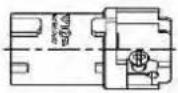
Combination for Power In (Consumer)
Combination for Power Out (Source)
Typical application

mains supply
OUT
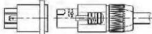
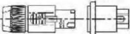
IN

![8.00 mm [0.315°] 20.00 mm [0.787°] Da](/content/2026/05/997378/images/2d415329d02121681c23d5e4c9e36791cedcdc19c35ba1e8b8fa66bfdf05761b.jpg)
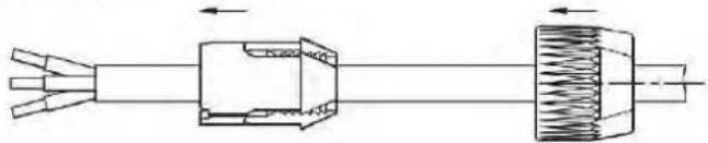
Cable Preparation
white chuck Da = 5.00 [0.197"] - 11.00 [0.433"]
black chuck Da = 9.50 [0.374"] - 15.00 [0.59"]
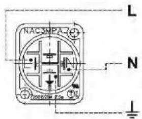
Wiring
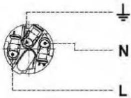
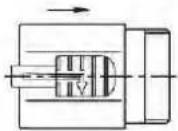
Assembling
natural_image
Pure mechanical diagram showing a shaft connected to a block and then to a spring, with no text or symbols present.Wiring
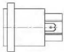
Panel Cutout (Rear Side)
![19.00 mm [0.748°] 24.00 [0.945°] mm 3.50 [0.138°] mm 23.60 [0.928°] mm](/content/2026/05/997378/images/3b2c3bc3c8b9445da29449bdd7cc22eb6c033e9673ca439cdae3c700a3f00e76.jpg)

ALIMENTAZIONE

POWER SUPPLY

ALIMENTATION

STROMVERSORGUNG
Before connecting the device to the mains, make sure the supply voltage matches the one indicated on the back of the device.
The fuse for power circuit protection shall be replaced only with fuses having the same electrical features and value.
Before replacing the fuse, disconnect the device from the power socket. Different fuses, mainly if featuring higher capacity, could damage the device. Were you not sure to be able to carry out this operation on your own, please contact your dealer.
natural_image
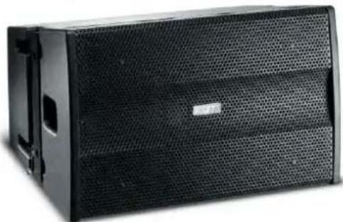
Black rectangular electronic device with perforated grille and 'F2T' logo, no visible text or symbols on bodyAddressing the growing demand for a compact and portable professional sound system, QUBE developed the QSA112/QSA112.0 constant curvature line array. Thys system is mostly dedicated to fixed installation and to sound rental companies, which are looking for equipment with the best ratio performance/portability at a very affordable price. The QSA112/QSA112.0 delivers extraordinary power handling, clarity, flexibility and, of course, stunning sound in an attractive, easy to handle affordable package.
natural_image
Black audio amplifier speaker with mesh grille and ventilation slots (no visible text or symbols)Two way, true line array full-range / bi-amp system, in bass reflex. 1 x 12" (3" voice coil) custom neodymium woofers granting high excursion and power handling. 3 x 1" (1.7" voice coil) custom neodymium compression drivers coupled to a waveguide with 100°H dispersion. The two models have different wave guide arrangement and cabinet shape to provide 15°V dispersion for QSA112A and 5°V dispersion for QSA112.0A. Originally born as constant curvature line array, the QSA112A have the advantage to cover wide vertical angle with small cabinets, very easy set-up and uniform audience coverage. When a bigger system is required the QSA112.0 cabinet permit to construct a "J" array configuration and cover long distance with impressive SPL.
The QSA112 / QSA112.0 easy handle (bi-amp mode) 600W on the LF and 240W on the HF section with a peak SPL 130dB (LF) / 138dB (HF). High quality passive crossover network offering maximum reliability, with built-in soft thermal protection for the HF components with autoreset. Bi-amp or full-range passive mode selection from the rear panel. High frequency shelving EQ switch (-3dB, 0dB, +3dB) allows effective amplitude shading technique, to evenly uniform the SPL of the mid-high frequencies in the listening area.
The speaker is made with birch plywood finished with scratch resistant paint. Integrated handles and mechanical hardware for suspension with 10:1 safety factor are included.
The SP27 is a digital signal processing controller programmed to optimize the performances of the total system. The SP22 QSA/1 is a digital signal processing controller made in a plug in module for QUBE rack amplifiers, to optimize the performance of the total system.
QSA 112.0
Constant Curvature Line Array
natural_image
Black FBT audio amplifier box with mesh grille and ventilation slots (no visible text or symbols)QSA 112
Constant Curvature Line Array
natural_image
Black audio amplifier box with mesh grille and ventilation slots (no visible text or symbols)Powered Constant Curvature Line Array speaker
natural_image
Black FET audio amplifier box with mesh grille and ventilation slots (no visible text or symbols)QSA 112A
Powered Constant Curvature Line Array speaker
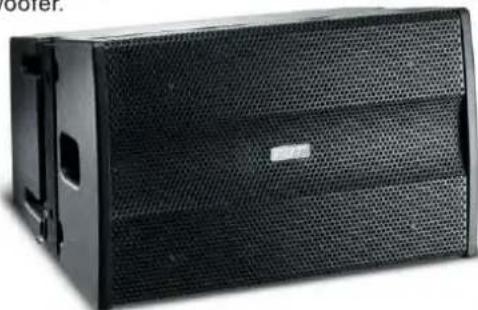
The QSA 112A and QSA112.0 A is a compact two way powered line array speaker system. It features a B&E 12" high excursion LF neodymium woofer and three 1" exit (1.7" voice coils) neodymium HF drivers which are coupled to three waveguide providing 100°H dispersion. The two models have different waveguide arrangement and cabinet shape to provide 15°V dispersion for QSA112A and 5°V dispersion for QSA112.0A. Originally born as constant curvature line array, the QSA112A have the advantage to cover wide vertical angle with small cabinets, very easy set-up and uniform audience coverage. When a bigger system is required, the QSA112.0 cabinet permit to construct a J-array configuration and cover long distance with impressive SPL.
The built in power amplifier consists of an 1100w Class D for the LF and a 300w Class G for the HF. The power amp also provides 2 sets of dipswitches with factory presets to adapt the QSA 112's EQ contour to
particular system configuration and the 2nd. set of dipswitches provides 8 different delay settings. Additional features include: Gain adjustment from -9dB to +3 dB, four LED indicators operation status, ground lift switch, balanced XLR - F input, balanced XLR-M Loop output, auto resetting AC line circuit breaker, two Neutrik® Powercon AC connectors (one main AC in, 1 AC loop out to supply AC power to up to 3 additional QSA 112A speakers). The QSA 112A/112.0A cabinet is constructed with 18mm (3/4") Baltic birch plywood and finished with scratch and scuff resistant black paint. Ergonomically placed handles and mechanical hardware for suspension with a 10:1 safety factor are provided. The QSA 112a/112.0a is an excellent choice for small to large sized venues when line array performance is desired and a fast and easy set up is required, as such is the case with a ground stacked system. Using an optional Qube SS - 212 speaker mounting pole allows one or two QSA 112A cabinets to be placed on top of a QSA 118SA subwoofer.
natural_image
Black audio amplifier speaker with mesh grille and ventilation slots (no visible text or symbols)QSA 112.0 A
Powered Constant Curvature Line Array speaker
natural_image
Black rectangular electronic device labeled 'F2T' with mesh grille and ventilation slots (no readable text beyond label)QSA 112A
Powered Constant Curvature Line Array speaker
natural_image
Black audio amplifier speaker with mesh grille and ventilation slots (no visible text or symbols)QSA 118S
Line Array Subwoofer
The QSA118S is a compact, high power, flyable subwoofer system using a custom B&C 18" woofer in bass reflex configuration. The woofer handles a 1400W furnishing a SPL of 132dB. Built using a 13-layer birch plywood and extra textures scratch resistant enclosure (18mm / 0.71") with integrated handles and mechanical hardware for suspension.
1 x 18" (4" voice coil) B&C custom woofer granting high excursion and power handling. Extended frequency response to 35Hz. QSA118S can be suspended or ground-stacked, 35mm pole mount socket. Four optional castors facilitate quicker and easier load ins and load outs.
natural_image
Black rectangular electronic device with mesh grille and 'F3T' logo, no visible text or symbols on bodyQSA 118SA
18" Bass Reflex Powered Subwoofer
natural_image
Black rectangular electronic device with a perforated grille and 'FBT' logo on the front panel (no readable text or symbols beyond branding)The QSA118SA is a powered compact bass reflex cabinet subwoofer. It features a B&C 18^th high excursion woofer powered by an 800W RMS Class D (PWM) power amplifier. Only the best quality European electronic parts are used in the power amp module circuitry to provide superb specifications, reliability and longevity. The QSA118SA has been specifically designed as the companion subwoofer system for the QSA112A two way line array cabinets, although it can be used with any sound system to provide additional LF reinforcement. Frequency response is from 35Hz to 120Hz and a single QSA118SA provides 137dB SPL.
The power amp module provides 2 sets of dipswitches with factory presets: 1 set of 4 switches provides 8 different EQ curves to adapt the QSA118SA's EQ contour for either ground stacked (4 EQ settings) or flying applications (4 EQ settings) as well as 180^ phase reversal.
The 2nd. set of dipswitches provides 8 different delay settings, allowing delay adjustments from .25 meters to 32 meters (9.75"-105ft.). A rotary potentiometer allows adjustment of gain settings from -9dB to +3dB for precise gain control. Additional power amp module features include: four led indicators for the power amps operation status (pwr on, overload, limit and protect), a ground lift switch, a balanced XLR-F input connector, a balanced XLR-M loop output connector to daisy chain the signal input to additional QSA118SA subwoofers, an auto resetting AC line circuit breaker, two Neutrik powercon AC connectors (one main AC IN, and one AC LOOP OUT to supply AC power to an additional QSA118SA or to power two QSA112A line arrays). This AC LOOP OUT powering system eliminates the need to connect lengthy individual AC power cables to each QSA118SA (or two QSA112A line array cabinets) from the nain AC power source and allows a quicker, more convenient multiple array cabinet system set up whether in a suspended or a ground stacked permanent or portable system configuration. The QSA118SA cabinet is constructed with 18mm (3/4") Baltic birch plywood and finished with scratch and scuff resistant black paint. Ergonomically placed integrated handles and mechanical hardware for suspension with a 10:1 safety factor are provided. The QSA118SA also features a top mount 35mm (1.4") satellite pole mount. With use of the optional QUBE SS-212 speaker mounting pole, one or two QSA112A two way line array cabinets can be placed on top of a QSA118SA subwoofer. The side mounted hardware is used to securely lock the QSA112A cabinets together while the SS-212's adjustable angle pole provides aiming flexibility.
QSA 118SA
18" Bass Reflex Powered Subwoofer
natural_image
Black rectangular electronic device with mesh grille and 'FBT' logo on front panel (no readable text or symbols beyond branding)| Configuration | Way 2 |
| Built-in amplifier cont. rms LF/HF | Watts 800/200 |
| Built-in amplifier max. rms LF/HF | Watts 1100/300 |
| Frequency response | @-6dB 60Hz - 20KHz |
| Low frequency woofer | inch 12 - 3 coil - neodymium |
| High frequency driver | inch 3x1 - 1.7 coil - neodymium |
| Maximum SPL cont/peak | dB 129 / 139 |
| Dispersion | H x V 100° x 5° |
| AC Power requirements | VA 800 |
| Power cord | m 5 |
| Net dimensions (WxHxD) | inch (15"x23,6"x17,9") |
| Net weight | lbs 73,75 |
QSA 112A
| Configuration | Way 2 |
| Built-in amplifier cont. rms LF/HF | Watts 800/200 |
| Built-in amplifier max. rms LF/HF | Watts 1100/300 |
| Frequency response | @-6dB 60Hz - 20KHz |
| Low frequency woofer | inch 12 - 3 coil - neodymium |
| High frequency driver | inch 3x1 - 1.7 coil - neodymium |
| Maximum SPL cont/peak | dB 129 / 139 |
| Dispersion | H x V 100° x 15° |
| AC Power requirements | VA 800 |
| Power cord | m 5 |
| Net dimensions (WxHxD) | inch (15"x23,6"x17,9") |
| Net weight | lbs 73,75 |
QSA 118SA
| Configuration | Way 1 |
| Built-in amplifier cont. rms LF/HF | W RMS 900 |
| Built-in amplifier max. rms LF/HF | W RMS 1200 |
| Frequency response | @-6dB 35hz - 120hz |
| Low frequency woofer | inch 18 - 4 coil |
| High frequency driver | - |
| Maximum SPL cont/peak | dB 133 / 137 half space |
| Dispersion | H x V omni |
| AC Power requirements | VA 800 |
| Power cord | m 5 |
| Net dimensions H x L x W | inch (22,25"x23,82"x27,36") |
| Net weight | lbs 128 |
| QSA 112 | QSA 112.0 | |
| Configuration | Way 2 | Way 2 |
| Recommended amplifier (Bi-Amp LF/HF) | W RMS 700 (600 / 240) | W RMS 700 (600 / 240) |
| Long term power (Bi-Amp LF/HF) | W RMS 350 (300 / 120) | W RMS 350 (300 / 120) |
| Short term power IEC 268-5 (Bi-Amp LF/HF) | W RMS 1400 (1200 / 480) | W RMS 1400 (1200 / 480) |
| Nominal impedance (Bi-Amp LF/HF) | Ohm 8 (8 / 8) | Ohm 8 (8 / 8) |
| Frequency response | @-6dB 68Hz - 20KHz | @-6dB 68Hz - 20KHz |
| Low frequency woofer | inch 12 - 3 coil - neodymium | inch 12 - 3 coil - neodymium |
| High frequency driver | inch 3x1 - 1.7 coil - neodymium | inch 3x1 - 1.7 coil - neodymium |
| Maximum SPL cont (Bi-Amp LF/HF) | dB 127 (127 / 135 ) | dB 127 (127 / 135 ) |
| Maximum SPL peak (Bi-Amp LF/HF) | dB 130 (130 / 138) | dB 130 (130 / 138) |
| Dispersion | H x V 100° x 15° | H x V 100° x 5° |
| Input connectors | 2 x Speakon NL4 in & throu | 2 x Speakon NL4 in & throu |
| Net dimensions (WxHxD) | inch 15.03" x 23.81" x 17.91" | inch 15.03" x 23.81" x 17.91" |
| Net weight | Ibs 66.13 | Ibs 66.13 |
QSA 118S
| Configuration | Way 1 |
| Recommended amplifier (Bi-Amp LF/HF) | W RMS 1400 |
| Long term power (Bi-Amp LF/HF) | W RMS 700 |
| Nominal impedance (Bi-Amp LF/HF) | Ohm 4 |
| Frequency response | @-6dB 35hz - 400hz |
| Low frequency woofer | inch 18 - 4 coil |
| High frequency driver | - |
| Maximum SPL cont (Bi-Amp LF/HF) | dB 133 half space |
| Maximum SPL peak (Bi-Amp LF/HF) | dB 138 half space |
| Dispersion | H x V omni |
| Input connectors | 2 x Speakon NL4 in & throu |
| Net dimensions (WxHxD) | inch 22.24" x 23.81" x 27.36" |
| Net weight | lbs 123.45 |
QSA 112.0A
AES LONG TERM APPLICABLE POWER denotes the thermal power that can be dissipated by the loudspeaker or by the individual drivers when operated in BI-AMP mode. This value is

measured in accordance with the AES standard, which involves a 2 hour test with pink noise signal, crest factor of 2. Power is determined by the square of the RMS voltage divided by the minimum impedance of the loudspeaker or the individual driver.
Although the POWER OF THE RECOMMENDED AMPLIFIER is not measured, and it takes account of the dynamic capacities of the speakers to withstand short duration power peaks. The value supplied corresponds to the RMS power required of the amplifier in order to supply the test signal (pink noise with crest factor 2) utilised to measure AES power.
An amplifier of this power, if used with music signals with crest factor greater than or equal to 6dB, makes it possible to get the best performance out of the speaker, delivering a long term power output that is no higher than the AES power of the loudspeaker.
On the contrary, when using highly compressed music signals or if the amplifier volume is increased to the point of intensive clipping, then the effective long term power tends to reach or even exceed the RMS output of the amplifier, resulting in irreversible damage to the speakers.
With signals of this type it is always advisable to use an amplifier whose RMS output is identical to the speaker AES power, while taking care to ensure that the signal supplied is such that the amplifier is not caused to function in clipping mode too frequently.
IEC268-5 SHORT TERM APPLICABLE POWER corresponds to the power that the loudspeaker can withstand for a very short time interval and it is calculated on the basis of the maximum peak voltage that can supply to the loudspeaker. Capacities in terms of SPL in transient components of music signals, effectively correspond to the short term applicable power value; therefore, the max. SPL value specified in the technical specifications table is calculated on the basis of this power value
WARNING: the power value that effectively corresponds to the thermal capacity of the loudspeaker to dissipate electrical energy over the long term is represented by the AES value. All other values refer to the "transient capacity" of the loudspeaker to accept power inputs, correlated with the nature of the audio signal that the drivers are destined to reproduce.
BI-AMP PASSIVE SYSTEM 17.200W (SPL 150dB) Line array speaker system ( Larger venues)
Configuration:
8 × QSA 112
8×QSA 118S
6 × PA 360
1 x SP 26
Accessories:
2×HSA 210
1×QFC 12W
1 x SPL 4/2
2 × CBL 2/4
4 × CBL 15/4
Two way speaker
Subwoofer
Power Amplifier
Digital controller
Hanging hardware
Flight case
Patch panel
Multipole speaker cable 2 mt
Multipole speaker cable 3 mt
N.B. only one PA360 power unit can be used for driving 4 satellites with a load of 2 Ohms per channel
flowchart
graph TD
    A["Speaker 1"] --> B["PA360 Unit 1"]
    A --> C["PA360 Unit 2"]
    D["Speaker 2"] --> E["PA360 Unit 1"]
    D --> F["PA360 Unit 2"]
    G["Speaker 3"] --> H["PA360 Unit 1"]
    G --> I["PA360 Unit 2"]
    J["Speaker 4"] --> K["PA360 Unit 1"]
    J --> L["PA360 Unit 2"]
    M["Speaker 5"] --> N["PA360 Unit 1"]
    M --> O["PA360 Unit 2"]
    P["Speaker 6"] --> Q["PA360 Unit 1"]
    P --> R["PA360 Unit 2"]
    S["Speaker 7"] --> T["PA360 Unit 1"]
    S --> U["PA360 Unit 2"]
    V["Speaker 8"] --> W["PA360 Unit 1"]
    V --> X["PA360 Unit 2"]
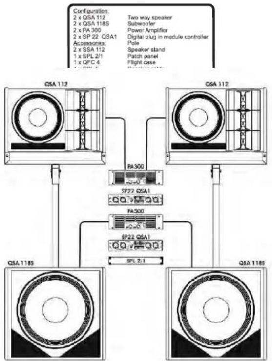
FULL RANGE PASSIVE SYSTEM 3200W (SPL 135dB)
flowchart
graph TD
    A["QSA 112"] -->|Configuration: 2 x QSA 112, 2 x QSA 1185, 2 x PA 300, 2 x SP 22 QSA1, Accessories: 2 x SSA 112, 1 x SPL 2/1, 1 x QFC 4, QSA 1185] --> B["QSA 112"]
    B --> C["SP22 QSA1"]
    B --> D["SP22 QSA1"]
    B --> E["SPL 2/1"]
    B --> F["SP22 QSA1"]
    B --> G["SP22 QSA1"]
    B --> H["SP22 QSA1"]
    B --> I["SP22 QSA1"]
    B --> J["SP22 QSA1"]
    B --> K["SP22 QSA1"]
    B --> L["SP22 QSA1"]
    B --> M["SP22 QSA1"]
    B --> N["SP22 QSA1"]
    B --> O["SP22 QSA1"]
    B --> P["SP22 QSA1"]
    B --> Q["SP22 QSA1"]
    B --> R["SP22 QSA1"]
    B --> S["SP22 QSA1"]
    B --> T["SP22 QSA1"]
    B --> U["SP22 QSA1"]
    B --> V["SP22 QSA1"]
    B --> W["SP22 QSA1"]
    B --> X["SP22 QSA1"]
    B --> Y["SP22 QSA1"]
    B --> Z["SP22 QSA1"]
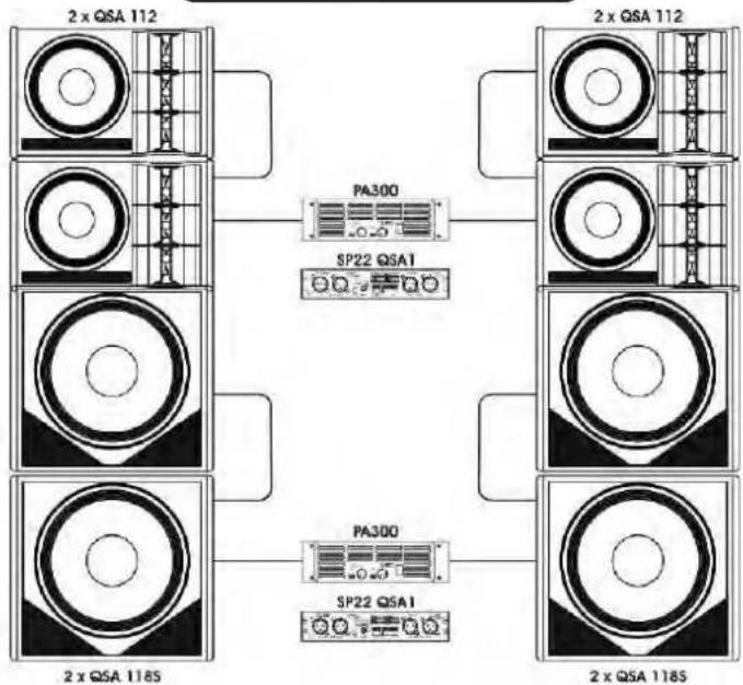
FULL RANGE PASSIVE SYSTEM 5000W (SPL 140.5dB) Compact line array system (Mid sized venues)
| Configuration: | |
| 4 x QSA 112 | Two way speaker |
| 4 x QSA 118S | Subwoofer |
| 2 x PA 300 | Power Amplifier |
| 2 x SP 22 QSA1 | Digital plug in module controller |
| Accessories: | |
| 2 x VMA 112 | Woodden support |
| 1 x QFC 8W | Flight case with wheels |
| 1 x SPL 2/1 | Patch panel |
| 1 x PLC 1B | Blank panel |
| 4 x CBL 5 | Speaker cable 5 mt. |
| 4 x CBL 15 | Speaker cable 15 mt. |
flowchart
graph TD
    A["2 x QSA 112"] --> B["PA300"]
    C["2 x QSA 112"] --> D["SP22 QSA1"]
    E["2 x QSA 1185"] --> F["PA300"]
    G["2 x QSA 1185"] --> H["SP22 QSA1"]
    B --> I["2 x QSA 112"]
    D --> J["2 x QSA 112"]
    F --> K["2 x QSA 1185"]
    H --> L["2 x QSA 1185"]
POWERED SYSTEM 5600W (SPL 141.5dB)
Line array speaker system (Mid sized venues)
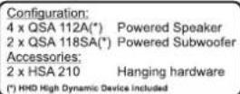
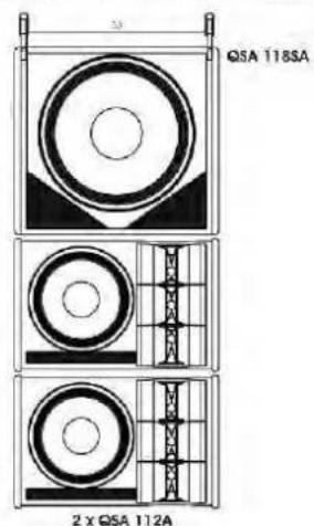
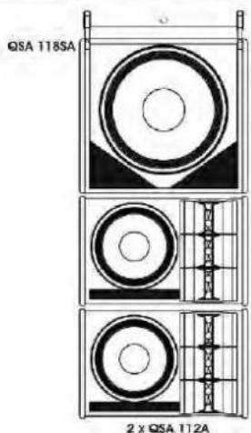
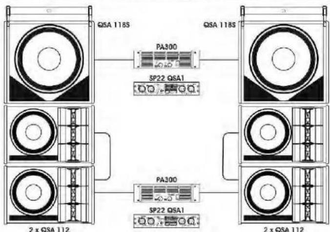
FULL RANGE PASSIVE SYSTEM 4000W (SPL 139dB) Line array speaker system (Mid sized venues)
| Configuration: | |
| 4 x QSA 112 | Two way speaker |
| 2 x QSA 118S | Subwoofer |
| 2 x PA 300 | Power Amplifier |
| 2 x SP 22 QSA1 | Digital plug in module controller |
| Accessories: | |
| 2 x HSA 210 | Hanging hardware |
| 1 x QFC 12W | Flight case |
| 1 x SPL 4/2 | Patch panel |
| 2 x CBL 5 | Speaker cable 5 mt |
| 4 x CBL 15 | Speaker cable 15 mt |
flowchart
graph TD
    A["QSA 118S"] -->|PA300| B["SP22 QSA1"]
    B --> C["QSA 118S"]
    D["2 x QSA 112"] -->|PA300| E["SP22 QSA1"]
    E --> F["2 x QSA 112"]
    style A fill:#f9f,stroke:#333
    style D fill:#f9f,stroke:#333
    style B fill:#ccf,stroke:#333
    style F fill:#ccf,stroke:#333
D EINGÄNGE
I CONNETTORI
UK CONNECTORS
F CONNECTEURS
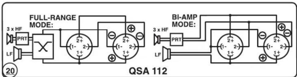
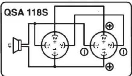
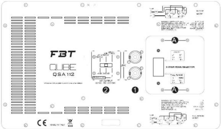
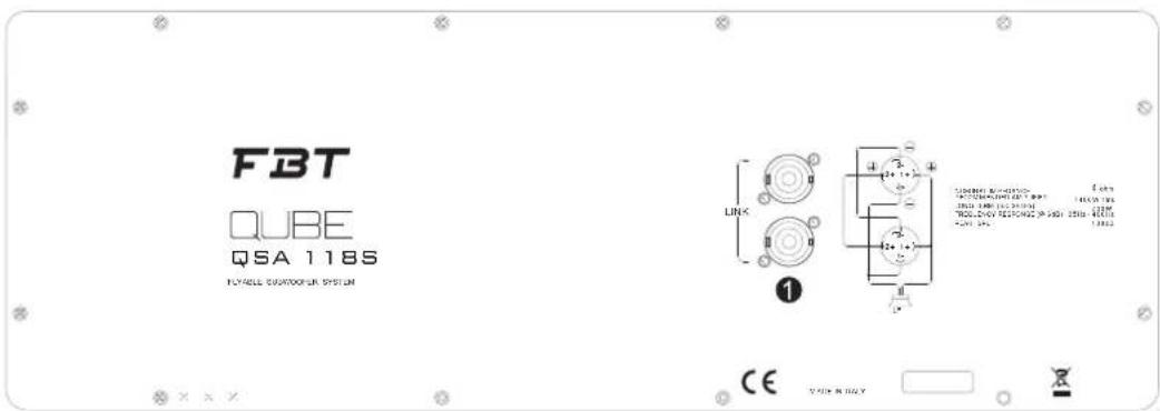
The SPEAKON (1) sockets are wired in parallel; one socket can be used to connect the loudspeaker to the output of a power amplifier, while the other can be used to connect a second loudspeaker.
This type of connector ensures a reliable and trouble-free connection and is therefore always recommended for speaker power inputs.
CAUTION
IT IS ADVISABLE TO USE AN AMPLIFIER WITH AN RMS OUTPUT THAT IS LOWER OF 1400 W RMS
QUBE loudspeakers incorporating a passive crossover and equipped with a crossover operating mode selector (X-OVER MODE SELECTOR).
The crossover modes are either FULL-RANGE (passive) or BI-AMP.
In FULL-RANGE mode the loudspeaker is driven by a single amplifier and the internal crossover splits the audio frequency spectrum into two bands, feeding lower frequencies to the woofer and higher frequencies to the HF unit.
Using BI-AMP mode makes it possible to obtain the maximum performance from the drivers by using two amplifiers, one for the woofer and one for the HF unit. In this case the internal crossover is inhibited so that all filtration and, if necessary, equalisation of the drivers must be performed externally.
WARNING: the drivers are not protected in this mode so, to avoid the risk of damaging the drivers, it is essential to comply with the prescriptions (given in the following table) concerning maximum power, cut-off frequencies, and the slopes of the external electronic filter.
To obtain the maximum performance in BI-AMP mode we recommend using a speaker system digital processor with appropriate settings for the crossover, limiter, equalizer, and delay to achieve temporal alignment between woofer and HF unit.
The table shows the power outputs, measured in accordance with the AES standard, that are acceptable by the loudspeaker in FULL-RANGE mode or by the individual drivers in BI-AMP mode..
WARNING: the recommended amplifier makes it possible to exploit the full dynamic potential of the loudspeakers to obtain the maximum sound quality and SPL, but it does not guarantee the protection of the speakers in any condition of use; in the case of a highly compressed music program or if the amplifier is driven to clipping levels the drivers may be damaged due to overheating or excessive cone excursion.
For music programs with reduced dynamics and pronounced distortion it is advisable to use an amplifier with an RMS output that is equal to or lower than the value given in the table to avoid exceeding the heat dissipation capacity of the drivers. In any event, driving the amplifier in clipping mode results in a substantial rise in the power supplied to the HF unit, which may therefore be damaged despite tripping of the protection in the internal crossover in FULL-RANGE mode.
In passive mode a HF compensation switch enables the user to set the performance according to his/her personal taste and to the environment acoustics.
The upper array modules can be set to obtain greater HF output power and so to reach distant areas (e.g. a balcony) and to attenuate the lower modules for a lower SPL towards the first rows of the venue; in this way all the listening areas are handled gradually and optimally.
+3 dB (LONG THROW): coverage of distant areas.
0dB (MID THROW): coverage of mid distances.
-3dB (SHORT THROW): coverage of short distances.
This picture shows an application example for the HF level selecting device on 5 QSA112 speakers
1_PWR: the LED illuminates to indicate that the processor is switched on 2_GND/LIFT: switch to isolate the chassis ground and the signal ground to avoid ground loops, which can cause hum problems.
3_LINK-LINE IN: electronically balanced input and output connectors; LINE IN enables the connection of a preamplified signal such as a mixer output; LINK enables the same signal to be relayed to several speakers.
5_SENS: to adapt speaker sensitivity to the source signal. When using high power source signals such as mixer outputs (+20dB) it is advisable to set the potentiometer from "0" to "3dB" to increase the signal to noise ratio and avoid overloading the input converters with resulting significant loss of signal quality.
4_OVD: this LED illuminates when the input signal is too high.
6_PRG SELECT: 8 equalisation presets to adapt speaker response to the specific needs of the installation can be selected using the three dipswitches. Refer to the "PROGRAM SELECT CHART" (fig.1 pag 26) to choose the best preset for your application. The "SUB" dipswitch activates a high pass crossover for use with a sub-woofer.
7_METERS DELAY: 8 dip-switches to control a digital delay line on the input signal; this makes it possible to compensate for vertical alignment differences between subwoofer and satellites or to create distributed lines of speakers whose output reaches the listening point simultaneously, thereby eliminating undesirable echo effects. The delay displayed on the control panel is in metres (from 0.25 to 63.75 metres in 25 cm steps). Example: to set a delay of 37.25 metres, activate dipswitches 1 (32m), 4 (4m), 6 (1m), and 8 (0.25m), for a total of 32 + 4 + 1 + 0.25 = 37.25m .
8_LIMITER: this LED illuminates when the speaker input limiter trips to prevent thermal overloads, excessive cone excursion, and distortion. When sound source volume is increased in these conditions the speaker volume will not increase correspondingly.
8_PRT: when this led lights on it indicates the internal amplifier malfunction or failure: to reset the system disconnect/connect the power supply cord by observing the procedure described on page 3 of this manual, if the led continues being lighted on, refer to a qualified technical-service center.
9_FUSEHOLDER: Holder for the power circuit protection fuse. If the fuse blows, it must only be replaced by a fuse with the same electrical characteristics. See description on page 6
10_ See description on page 3-4-5
QSA118SA:
PHASE: 180deg. phase rotation PRG SELECT: it selects 4 volume steps and 2 kinds of equalization (ground/hung) (see fig.1 pag.26).
QUBE speakers feature 8 different presets designed to adapt the speaker answer to the environment and create a uniform coverage pattern. The selection can be made through 3 dip-switches located in the control panel on the rear of the speaker and called "PRG SELECT". The tables in fig.1 show the correspondence between the dip-switch settings and the presets.
The presets are a quick and precise tool for installers or sound technicians to speed up the system setup according to the most frequent usage conditions.
QSA 112A
ARRAY CONFIGURATION WITH 1/2 SPEAKERS:
□-3dB coverage of short distances
□ 0dB coverage of mid distances
ARRAY CONFIGURATION WITH 3 SPEAKERS:
□ -3dB coverage of short distances
□ 0dB coverage of mid distances
□ +3dB coverage of distant areas
ARRAY CONFIGURATION WITH 4 SPEAKERS OR MORE:
□-3dB coverage of short distances
□ 0dB coverage of mid distances
□ +3dB coverage of distant areas
The upper array modules need to be set to obtain greater output power and so to reach distant areas (e.g. a balcony) and to attenuate the lower modules for a lower SPL towards the first rows of the venue; in this way all the listening areas are handled gradually and optimally. (fig. 2)
QSA 118SA:
The presets deliver 2 different EQ curves and modify the volume, so to make it possible to adapt the SUB level to the SATELLITE level.
GROUND 0dB: to be used when the SUB is laid on the ground or on the stage or in any case very close to a highly reflecting surface.
GROUND -3dB: same preset as GROUND but with a -3dB attenuation of the volume to adapt the SUB emission to the satellite.
GROUND +3dB: same preset as GROUND but with a +3dB amplification of the volume to adapt the SUB emission to the satellite.
GROUND +6dB: same preset as GROUND but with a +6dB amplification of the volume to adapt the SUB emission to the satellite.
HUNG 0dB: to be used when the SUB is suspended far from reflecting surfaces.
HUNG -3dB: same preset as HUNG but with a -3dB attenuation of the volume to adapt the SUB emission to the satellite.
HUNG +3dB: same preset as HUNG but with a +3dB amplification of the volume to adapt the SUB emission to the satellite.
HUNG +6dB: same preset as HUNG but with a +6dB amplification of the volume to adapt the SUB emission to the satellite.
Choose the preset depending on the total number of speakers in the system (QSA 112A + QSA 112.0A). If the system features more than 4 speakers in total, use the preset "≥4 SPKR".
QSA 112.0A
Choose the preset depending on the total number of speakers associated only to the QSA 112A model in the system. Depending on the selected configuration refer to the table for the most suitable preset.
N.B.: If the number of speakers is higher than 5, we recommend adding "Low Shelving" equalization at 700Hz/-3dB to the whole array.
PROGRAMMATION DES PRESET
F
| CONFIGURATION ARRAY | PRESET | N° TOTAL DE DIFFUSEURS POUR ARRAY | ||
| QSA112.0A | QSA112A | QSA112.0A | QSA112A | |
| 1 | 1 | 1/2 SPKR | 2 SPKR | 2 |
| 2 | 2 | 2/3 SPKR | 4 SPKR | 4 |
| 2 | 1 | 1/2 SPKR | 3 SPKR | 3 |
| 1 | 2 | 2/3 SPKR | 3 SPKR | 3 |
| 3 | 1 | 1/2 SPKR | 3/4 SPKR | 4 |
| 1 | 3 | 3 SPKR | 4 SPKR | 4 |
| 1 | 4 | 4 SPKR | 4 SPKR (+3dB) | 5 |
| 2 | 4 | 3 SPKR | 4 SPKR (+3dB) | 6 |
| 2 | 3 | 2/3 SPKR | 4 SPKR (+3dB) | 5 |
| 3 | 2 | 2 SPKR | 4 SPKR (+3dB) | 5 |
| 3 | 4 | 3 SPKR (+3dB) | 4 SPKR (+3dB) | 7 |
| 3 | 3 | 3 SPKR | 4 SPKR (+3dB) | 6 |
QSA 112A
Figure "A" show the clamp incline base of the pin positioning hole.
QUBE QSA models feature a suspension system embedded in the bearing structure. For arrays, you should only add the following accessories: the HSA 600 model flying bar, to be fixed to the system by means of an L clamp.
Using other fixing accessories may result in a dangerous instability with possible damage to persons or things.
ATTENTION
The pictures in this page show the array configurations allowed to meet the maximum weight safety parameters.
Even in recommended configurations, before hanging any QUBE system check the relevant load limits.
Before hanging the system check that the suspension system safety requirements provided for by the current regulations of the country of installation are met; this check shall be carried out by the person responsible for the flying structure.
F B T a c c e p t s n o responsibility for any damage to people and/or objects if the safety factor of all elements related to system suspension is not properly checked.
SOPRA IL SUBWOOFER QSA118S/118SA
WOODEN SUPPORT TO TILT DOWN (-7.5°)
QSA112/112A FITTED OVER QSA118S/118SA
SUPPORT POUR INCLINER (-7.5°) LE MODÈLE
QSA112/112A POSITIONNÉ SUR LE CAISSON
DE GRAVES QSA118S/118SA
natural_image
Technical line drawing of a mechanical cart with wheels and a flat plate (no text or symbols)WD-112
CARRELLO CON RUOTE PER TRASPORTO
DI 4 x QSA112/112A
TROLLEY WITH WHEELS TO TRANSPORT
4 x QSA112/112A
CHARIOT AVEC ROULETTES POUR LE
TRANSPORT DE 4 x QSA112/112A
natural_image
Technical line drawing of a mechanical component with an oval top view and labeled 'SIDE VIEW' (no other text or symbols)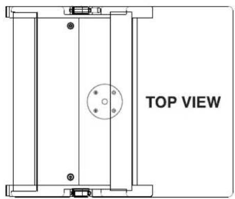
natural_image
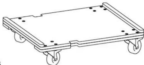
Line drawing of a four-wheeled cart with wheels and mounting holes (no text or symbols)WD-118S
CARRELLO CON RUOTE PER TRASPORTO
DI 2 x QSA118S/118SA
TROLLEY WITH WHEELS TO TRANSPORT
2 x QSA118S/118SA
CHARIOT AVEC ROULETTES POUR LE
TRANSPORT DE 2 x QSA118S/118SA
natural_image
Simple line drawing of a horizontal beam supported by two vertical supports, with a circular marker labeled '33' at the base (no text or symbols on the diagram itself)SS-212
SUPPORTO PER FISSAGGIO SU STATIVO DEI
MODELLI QSA112 SOPRA IL SUBWOOFER QSA118
SPECIALLY DESIGNED SPEAKER STAND FOR
MOUNTING QSA112 CABINET ON TOP OF A
QSA118 SUBWOOFER
SUPPORT POUR FIXATION SUR LE STATIF DES
MODÈLES QSA112 AU-DESSUS DU CAISSON
DE GRAVES QSA118
I
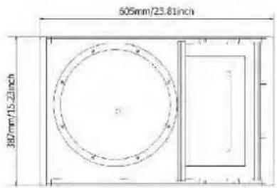
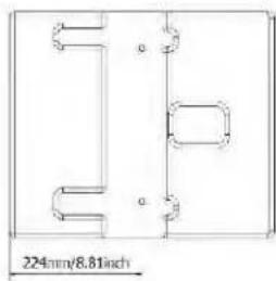
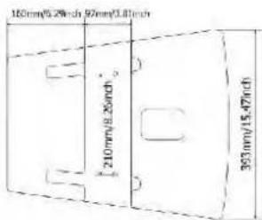
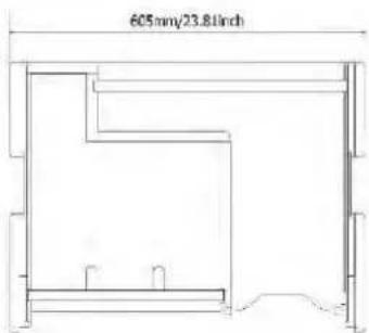
DIMENSIONI
UK
DIMENSIONS
F
DIMENSIONS
D
ABMESSUNGEN
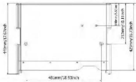
QSA 112.0
QSA 112.0A

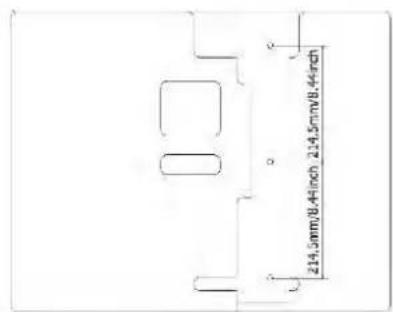
QSA 118S
QSA 118SA
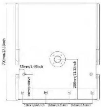
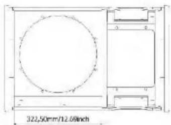
QSA 112
QSA 112A
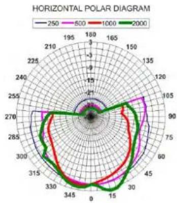
I DIAGRAMMI F DIAGRAMS
QSA 112A QSA 112
DIAGRAMS DIAGRAMME
UK
D
radar
| Angle | 250 | 500 | 1000 | 2000 | |-------|-----|-----|------|------| | 0 | 0 | 0 | 0 | 0 | | 30 | 15 | 25 | 50 | 75 | | 60 | 30 | 45 | 75 | 100 | | 90 | 45 | 60 | 100 | 125 | | 120 | 60 | 75 | 125 | 150 | | 150 | 75 | 90 | 150 | 175 | | 180 | 90 | 105 | 175 | 200 | | 210 | 105 | 120 | 200 | 225 | | 240 | 120 | 135 | 225 | 250 | | 270 | 135 | 150 | 250 | 275 | | 300 | 150 | 165 | 275 | 300 | | 330 | 165 | 180 | 300 | 325 | | 360 | 180 | 195 | 325 | 350 |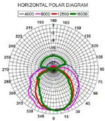
radar
| Angle | 4000 | 8000 | 12500 | 16000 | |-------|------|------|-------|-------| | 0 | 0 | 0 | 0 | 0 | | 30 | 15 | 27 | 15 | 27 | | 60 | 30 | 45 | 30 | 45 | | 90 | 45 | 60 | 45 | 60 | | 120 | 60 | 75 | 60 | 75 | | 150 | 75 | 90 | 75 | 90 | | 180 | 90 | 105 | 90 | 105 | | 210 | 105 | 120 | 105 | 120 | | 240 | 120 | 135 | 120 | 135 | | 270 | 135 | 150 | 135 | 150 | | 300 | 150 | 165 | 150 | 165 | | 330 | 165 | 180 | 165 | 180 | | 360 | 180 | 195 | 180 | 195 |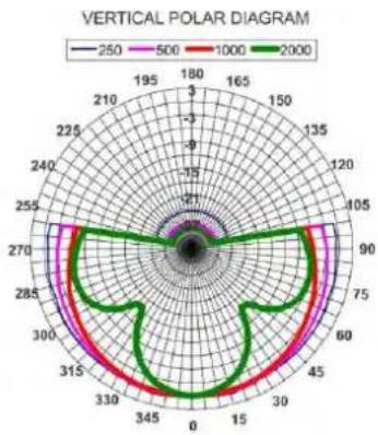
radar
| Angle (degrees) | 250 | 500 | 1000 | 2000 | | --------------- | ----- | ----- | ----- | ----- | | 0 | -21 | -21 | -21 | -21 | | 30 | -15 | -15 | -15 | -15 | | 60 | -5 | -5 | -5 | -5 | | 90 | 5 | 5 | 5 | 5 | | 120 | 15 | 15 | 15 | 15 | | 150 | 25 | 25 | 25 | 25 | | 180 | 30 | 30 | 30 | 30 | | 210 | 25 | 25 | 25 | 25 | | 240 | 15 | 15 | 15 | 15 | | 270 | 5 | 5 | 5 | 5 | | 300 | -5 | -5 | -5 | -5 | | 330 | -15 | -15 | -15 | -15 | | 360 | -21 | -21 | -21 | -21 |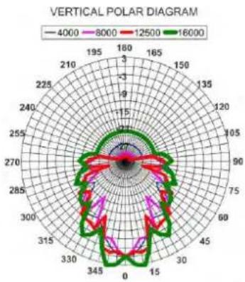
radar
| Angle | 4000 | 8000 | 12500 | 16000 | |-------|------|------|-------|-------| | 0 | 16 | 16 | 16 | 16 | | 30 | 15 | 15 | 15 | 15 | | 60 | 14 | 14 | 14 | 14 | | 90 | 13 | 13 | 13 | 13 | | 120 | 12 | 12 | 12 | 12 | | 150 | 11 | 11 | 11 | 11 | | 180 | 10 | 10 | 10 | 10 | | 210 | 9 | 9 | 9 | 9 | | 240 | 8 | 8 | 8 | 8 | | 270 | 7 | 7 | 7 | 7 | | 300 | 6 | 6 | 6 | 6 | | 330 | 5 | 5 | 5 | 5 | | 360 | 4 | 4 | 4 | 4 |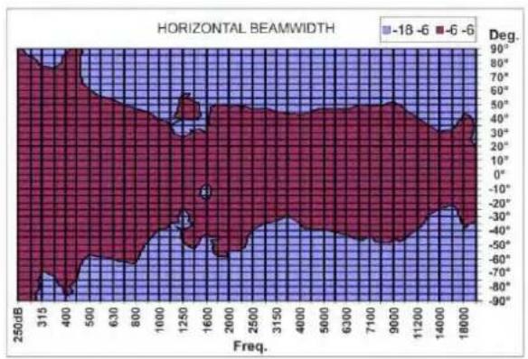
line
| Freq. | -18 | -6 | |-------|--------|--------| | 250 | 0 | 0 | | 315 | 0 | 0 | | 400 | 0 | 0 | | 500 | 0 | 0 | | 630 | 0 | 0 | | 800 | 0 | 0 | | 1000 | 0 | 0 | | 1250 | 0 | 0 | | 1600 | 0 | 0 | | 2000 | 0 | 0 | | 2500 | 0 | 0 | | 3150 | 0 | 0 | | 4000 | 0 | 0 | | 5000 | 0 | 0 | | 6300 | 0 | 0 | | 7100 | 0 | 0 | | 9000 | 0 | 0 | | 11200 | 0 | 0 | | 14000 | 0 | 0 | | 18000 | 0 | 0 |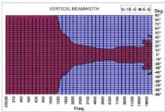
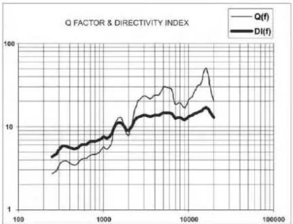
line
| x | Q(f) | DI(f) | | ------ | ---- | ----- | | 100 | ~3 | ~5 | | 1000 | ~8 | ~9 | | 10000 | ~25 | ~15 | | 100000 | ~35 | ~12 |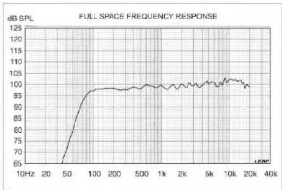
line
| Frequency | dB SPL | | --------- | ------ | | 10Hz | 65 | | 20 | 70 | | 50 | 85 | | 100 | 98 | | 200 | 99 | | 500 | 99 | | 1k | 99 | | 2k | 99 | | 5k | 100 | | 10k | 101 | | 20k | 100 | | 40k | 99 |QSA 118SA
QSA 118S
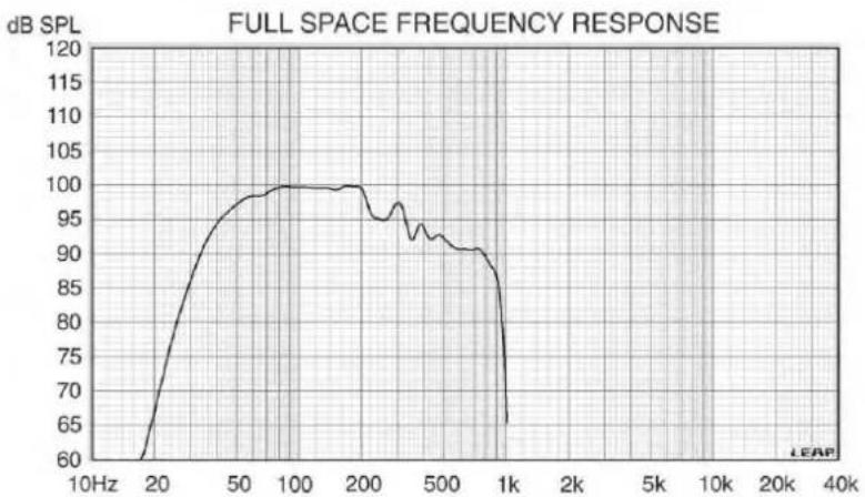
line
| Frequency | SPL (dB) | | --------- | -------- | | 10Hz | 60 | | 20 | 85 | | 50 | 98 | | 100 | 100 | | 200 | 100 | | 500 | 95 | | 1k | 65 | | 2k | 65 | | 5k | 65 | | 10k | 65 | | 20k | 65 | | 40k | 65 |Power amplifiers are mainly classified according to the type of output stage. Such classification is based on how long output devices remain active during each cycle. The most common classes of professional sound amplifiers are: AB, AB+B, D, G, H
.BAND-PASS (band-pass filter)
This is a device that, once given a centre frequency and a bandwidth, lets only the frequencies within the band specified by these parameters pass, attenuating the others.
CLIPPING
Digital distortion occurring when the amplitude of an input signal to a sampling device exceeds the dynamic range that the same device can manage.
COMPRESSOR
A device reducing the dynamic range of an audio signal. First, the threshold has to be set. Then, if the signal exceeds the threshold value, its gain is reduced.
CROSSOVER network
High- and low-pass filters used for speakers do not cut-off undesired frequencies; the roll-off (filter attenuation) occurs over a number of octaves. Common filter slope for speakers are 1st through 4th order, corresponding to 6dB/octave to 24 dB/octave.
DYNAMICS, dynamic range
The dynamic range of a sound is the ratio between the strong and powerful part of that sound, and its soft and light part; it is measured in dB.
HIGH PASS FILTER
It is a filter letting the frequencies above a certain threshold pass, and cutting the frequencies below such threshold. It is also called "low-cut filter".
LIMITER
It is special compressor designed to prevent the signal from exceeding a certain amplitude level.
PHASE
Considering given waves with different waveforms and frequencies, they are told to be "in phase" if they cross the time axis with the same slope at the same time. Otherwise, they are told to be "out-of-phase". The phase is a very important element of sound waves since it is essential to establish the result of the addition of several waves; for instance, two identical sounds with opposite phases cancel out.
PINK NOISE
The noise is said to be pink, as opposed to the white noise. It is a non periodic noise, which includes frequencies from the whole acoustic spectrum. However, unlike the white noise, it has higher amplitude at low frequencies and lower amplitude at high frequencies, so to adjust to the human ear sensitivity, that is less sensitive to lower frequencies.
SPL
Perceived sound volume or pressure, measured in decibels. The SPL is a function of signal amplitude.
THD
The ratio between the power of the fundamental tone at device output and the total power of all the harmonics in the frequency band at device output.
BAND-PASS (Filtre Passe-Bande)
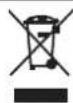
WARNING: Where affixed on the equipment or package, the barred waste bin sign indicates that the product must be separated from other waste at the end of its working life for disposal. At the end of use, the user must deliver the product to a suitable recycling centre or return it to the dealer when purchasing a new product. Adequate disposal of the decommissioned equipment for recycling, treatment and environmentally compatible disposal contributes in preventing potentially negative effects on the environment and health and promotes the reuse and/or recycling of equipment materials. Abusive product disposal by the user is punishable by law with administrative sanctions.
All information included in this operating manual have been scrupulously controlled; however FBT is not responsible for eventual mistakes. FBT Elettronica S.p.A. has the right to amend products and specifications without notice.
- TO REDUCE THE RISK OF FIRE OR ELECTRIC SHOCK DO NOT EXPOSE THIS EQUIPMENT TO RAIN OR MOISTURE
- IMPORTANT SAFETY INSTRUCTIONS
- THE DEVICE MUST BE CONNECTED TO THE MAINS THROUGH A POWER OUTLET WITH A PROTECTIVE EARTH CONNECTION.
- PRECAUTIONS
- POUR ÉVITER LE RISQUE DE CHOC ÉLECTRIQUE NE PAS OUVRIR LE COUVERCLE NE PAS UTILISER D'OUTILS MÉCANIQUES À L'INTÉRIEUR CONTACTER UN CENTRE D'ASSISTANCE QUALIFIÉ
- POUR ÉVITER LE RISQUE D'INCENDIE OU DE CHOC ÉLECTRIQUE NE PAS EXPOSER L'APPAREILLAGE À LA PLUIE OU À L'HUMIDIT
- INFORMATIONS DE SÉCURITÉ IMPORTANTES
- THE CABLE AND THE PLUG MUST HOLD THE UL OR CSA CERTIFICATION.
- Cable Preparation
- ALIMENTAZIONE
- POWER SUPPLY
- ALIMENTATION
- STROMVERSORGUNG
- QSA 112.0
- Constant Curvature Line Array
- QSA 112
- Powered Constant Curvature Line Array speaker
- QSA 112A
- QSA 112.0 A
- QSA 118S
- Line Array Subwoofer
- QSA 118SA
- 18" Bass Reflex Powered Subwoofer
- BI-AMP PASSIVE SYSTEM 17.200W (SPL 150dB) Line array speaker system ( Larger venues)
- CAUTION
- IT IS ADVISABLE TO USE AN AMPLIFIER WITH AN RMS OUTPUT THAT IS LOWER OF 1400 W RMS
- QSA118SA:
- QSA 118SA:
- QSA 112.0A
- ATTENTION
- WD-112
- WD-118S
- SS-212
- .BAND-PASS (band-pass filter)
- CLIPPING
- COMPRESSOR
- CROSSOVER network
- DYNAMICS, dynamic range
- HIGH PASS FILTER
- LIMITER
- PHASE
- PINK NOISE
- SPL
- THD
- BAND-PASS (Filtre Passe-Bande)
Brand : FBT
Model : QSA 118S
Category : Subwoofer