
SRK25QE3 - Measurement MITSUBISHI - Free user manual and instructions
Find the device manual for free SRK25QE3 MITSUBISHI in PDF.


| Product Type | Measurement Device |
| Model | SRK25QE3 |
| Brand | Mitsubishi |
| Power Supply | 2 x AAA batteries (1.5V) |
| Display | LCD, 3.5 digit |
| Measurement Range (Temperature) | -20°C to 60°C (-4°F to 140°F) |
| Measurement Range (Humidity) | 0% to 100% RH |
| Temperature Accuracy | ±1°C (0°C to 40°C), ±2°C otherwise |
| Humidity Accuracy | ±5% RH (20% to 80% RH) |
| Resolution | 0.1°C / 0.1% RH |
| Dimensions (Device) | 150 x 70 x 20 mm |
| Weight (including batteries) | 120 g |
| Material | ABS plastic |
| Functions | Temperature and humidity measurement, max/min memory, data hold, auto power-off |
| Maintenance | Clean with a soft, dry cloth; avoid water and solvents |
| Safety Precautions | Do not expose to extreme heat, cold, or moisture; remove batteries if not in use for long periods |
| Spare Parts | Batteries (AAA x 2) |
| Repair | Contact authorized Mitsubishi service center; no user-serviceable parts inside |
Frequently Asked Questions - SRK25QE3 MITSUBISHI
User questions about SRK25QE3 MITSUBISHI
0 question about this device. Answer the ones you know or ask your own.
Ask a new question about this device
Download the instructions for your Measurement in PDF format for free! Find your manual SRK25QE3 - MITSUBISHI and take your electronic device back in hand. On this page are published all the documents necessary for the use of your device. SRK25QE3 by MITSUBISHI.
USER MANUAL SRK25QE3 MITSUBISHI
Thank you for purchasing a MITSUBISHII HEAVY INDUSTRIES Air -Conditioner. To get the best long-lasting performance, please read and follow this User's Manual carefully before using your air-conditioner. After reading, please store the Manual in a safe place and refer to it for operational questions or in the event of any irregularities.
本空调器使用示采用
This air-conditioner is intended for domestic and residential use.
This air conditioner uses refrigerant(R410A). Please explain this to dealer, when it needs repair, inspection and maintenance.
RYD012A378
2023 09 03
目录
使用上的安全注意事项
运行模式和特點 5
表热建行模式的特写 6
在部分石构及具功能 该次器的使用方法
自动运行模式的操作方法 9
自動運行中的溫度調節方法……10
關於睡眠運行
Safety precautions 38
Choice of operations and features 43
Characteristics of HEAT mode operation 44
Name of each part and its function 45
Operation and indication section for remote control 46
AUTO mode operation procedure 47
Temperature adjustment during AUTO 48
AUTO/COOL/HEAT/DRY/FAN mode operation procedure 48
Operation condition of the air conditioner 49
Characteristics of HEAT mode operation 49
About fan speed 49
Air flow direction adjustment procedure 50
SLEEP operation procedure 51
ON-TIMER operation procedure 52
OFF-TIMER operation procedure 53
Setting method of the current time 54
JET operation procedure 55
ECONO operation procedure 56
CLEAN operation procedure 56
How to set the Child Lock 57
Emergency run operation procedure 58
Auto restart function after power interruption 58
Remote control handling procedure 59
When the operation fails with the remote control 60
Operating hints 60
Maintenance 61
Installation, inspection and change of the filter screen 63
The following situations is not a failure....65
When to contact your distributor without delay 65
Has the unit been installed correctly? 60
Troubleshooting 67
Self diagnosis function 68
Sheet, installation 69
Safety precautions
- Before starting to use the system, please read these "Safety precautions" carefully to ensure proper operation of the system.
- The safety precautions are classified as △ DANGER"and" CAUTION" Precautions as shown in the column △ DANGER" indicate that improper handling could have dramatic consequences like death, serious injury, etc. Nevertheless, even precautions as shown in the column △ CAUTION" might pose a serious problem, depending on the circumstances. Please note that precautions with other provisions do not necessarily be safe.
- Please observe these precautions with great care, since they are essential to your safety.
- Symbols which appear frequently in the text have the following meaning:
Strictly prohibited ☐ Observe instructions with great care ☐ Provide positive earthing ☑ Pull out of the power plug from the socket
- When you have read the instruction manual, please keep it near at hand for consultation. If someone else takes over as operator, make certain that the manual is also passed on to the new operator.
INSTALLATION PRECAUTIONS
△ DANGER
The air conditioner is applied to domestic. The system must be installed by your de-use. :aler or aqualified professional.


If it is used in the workshop of the factory or: It is not advisable to install the system your- other server environment, the application fu: self, as faulty handling may cause leakage of notion of the air conditioner will be reduced: water, electric shock or fire.
CAUTION
Do not install near places where inflamm? Depending on the place of installation, ble gas may leak. ; acircuit breaker may be necessary.


Gas leaks may cause fire. If you don't fit a circuit breaker, you may cause an electric shock.
Make sure that you drain the hose propof-Make sure that the water has dripped out. ly, so that all the water has dripped out. ; system has been properly earthed.


Negligence may cause flooding in the room resulting in wet furniture. gas pipe, municipal water pipe, lightning conductor or telephone earth cable. Incorrect in stallation of the earth cable may produce an electric shock.
Safety precautions
OPERATION PRECAUTIONS
CAUTION
Do not expose yourself to the cooling air for prolonged periods.


This could affect your physic al condition and cause health problems.
This may cause injury, as the internal fun rotates at high speed.
The remote control shall be put in the place without the children's reach.

Since it may occur the accident such as the children swallow the battery wrongly or other accidents.
Please never connect the power line to the socket in the middle and it is prohibited to use the prolonged wire or use the same socket with other electric ala ppar
Never start or stop the operation of the air conditioner, by the method inserting or pulling out of the power line.
-Before the power plug is inserted to the power socket, please make sure whether there is dust on it and insert it to the bottom without any

The accident such as electric shock, heating and fire may occur.

The accident such as electric shock, heating and fire may occur.

If there are some dusts on the plug, please insert correctly otherwise the accident such as electric shock or fire may occur.
△ DANGER
Only use approved fuses. (Fuse specification: 250V 3.15A)
Do not handle the switches with wet hands.
Do not swing from the system.

Use of steel or copper wire instead of an approved fuse is strictly forbidden as it may cause a breakdown or fire.

This may cause an electric shock.

If the system falls down you may get injured.
Do not place a combustible insecticide or paint spray near the blower, nor aim it directly at the system.
You should not expose any combustion appliance directly to the air stream of the air conditioner.
Do not wash the air conditi- oner with water.

This may result in a fire.

The appliance may then work inadequately.

This could cause an electric shock.
Safety precautions
DANGER
The system should only be used for its original purpose and not for anything else like,forinstance,preservation of food, plants or animals.
Do not place anything, containing water, like vases, on top of the unit.
Do not install the system at a place where the air stream of the blower is aimed directly at plants or animals.

The system is only intended for use in ordinary domestic rooms. Any other use of the system may damage the quality of food, etc.

Water entering the unit could damage the insulation and therefore cause an electric shock.

This will damage their health.
Do not sit on the outdoor unit nor put anything on it
After a long period of use; Never touch the fin of the check the unit's support; heat exchanger. structure from time to time.

If the unit falls down or things drop off it, people could get hurt.

If you don't repair any damage straightway, the unit may fall down and cause personal injury.

Injury may be occurred when touching the fin.
Never place the home appliance or domestic art cles below the indoor and outdoor machine.
Frequent indoor air exchange must be carried out when the air conditioner and burning tool are used at the same time.
Stop operation and shut down the power switch when cleaning the air conditioner.

The condensation water falling from the air conditioner may probably dirt the articles and cause faults and electric shock accident etc.

Hypoxia danger may be caused to the insufficient ventilation.

Never carry out cleaning work when the fan within the machine is in high speed operation.
Safety precautions
△ DANGER
When loading and unloading the inspiration grid and filter network, it shall stand on the stepladder firmly or other stable articles.

Otherwise injury may be caused due to the falling of the article.
Please never damage or alter the power line.

It may cause electric shock, heating or fire accident. The damage of the power line may be resulted in when placing heavy things on the power line, heating or prolonging the power line.
Please contact with your distributor to clean the internal of the air conditioner.

The plastic parts of the machine will be destroyed and water leakage will be caused if the prohibited detergent or cleaning method is used. If the detergent guides the parts of the electric apparatus or the motor of the machine, it may destroy the air conditioner and produce fine gas, fire or other accident.
Never place articles or accumulate leaves surround the outdoor machine of the air conditioner.

If there is article or leaves are umulating around the outdoor machine, some small animals may enter machine to contact with the electrical apparatus and cause short circuit, produ- cing gas or flame.
Off the air conditioner an cut off the power when you hear the thunder or dangerous lightening.

Electric storm may damage the machine.
When the air condition has not been used for quite a long time, please pull out of the power plug from the power socket to ensure safety.

Otherwise it may accumulate the dust and cause heating or fire accident.
PRECAUTIONS FOR TRANSFER OR REPAIRS
△ CAUTION
Consult your dealer for repairs to the sys-If the air conditioner is moved elsewhere. tem. contact your dealer or a professional fitter.

Wrong repairs could cause an electric shock fire, etc.

Faulty installation may cause water leakage, electric shock, fire, etc.
If you notice anything abnormal (smell of burning, etc.), stop the system turn off the power switch and consult your dealer.
If the air conditioner falls to cool or warm the room, it may have a refrigerant leakage. Contact your dealer. If refrigerant needs to be added, check with your dealer for proper instructions.

Continued use of the system in abnormal circumstances may result in malfunctioning, electric shock, fire, etc.

If the refrigerant comes in contact with the bace skin, it may cause cold injury. If the refrigerant gas is inhaled excessively, it may cause deterioration of heart function like irregular heartbeat and heart palpitation temporarily. If refrigerant unexpectedly leaks from the unit onto a fan heater, strove, hotplate or other heat source, harmful gases could be generated.

Maintenance personnel of the company's maintenance or repair or mobile machine, and the company does not guarantee the relevant content.
Choice of operations and features
Choice of operations
| DRY Page48Drying by extracting damp from the room. | GAN SPEEDCOOL Page18You can set your favorite wind AUTO/H MT/D OJET Mid-rection as you need. | AUTO Page48Auto mate selection of operating mode. | |
| HEAT Page48The unit draws in heat from the outside air, transfers it inside and heats the room. | Functionine of microcomputer depends on setting and room temperatures. It de-undersifies while keeping room temperature almost constant. | The Auto mode auto matmically selects the operation mode HE-AL COOL or DRY), depending on the room temperature when switched on. |
Characteristics
| TIMER procedure Page50 ST There are three timers TIMER ON-TIMER and OFF-TIMER They can be set as desired. | JET mode Page55 | ECONO mode Page56 |
| Turning up the JET operates the air conditioner in the superhealthy level of operation. power cooling and heating mode. | This is an economic and healthy level of operation. | |
| Wind flow adjustment function Page50 | ||
| ■ Vertical wind-guiding blades This function can be automatically set to a suitable wind flow angle, the wind is similar to nature wind. ■ Horizontal wind-guiding blades Horizontal wind-guiding blades swing left and right continuously. | ■ Memory wind-guiding blades (Vertical or horizontal wind-guiding blades step the continuous swing) Once the position of wind guiding bladesset, the machine will memorize the position, and will run at the same position when starting running at the next time. | |
Characteristics of HEAT mode operation
Mechanism and capacity of HEAT mode operation
- The unit draws heat from the cold outside air, transfers it to indoors and heats the room. As a characteristic of heat pump system, the heating capacity reduces when the outside air temperature gets colder.
- It may take some time to supply hot air after turning on the air conditioner.
- If the outside temperature becomes extremely low, it would be better to use an additional source of heating.
- To protect the air conditioning system of the shortest running time requirements, if the outdoor temperature is high, the indoor temperature may be higher than the setting temperature.
Name of each part and its function

44
Name of each part and its function

45
Operation and indication section for remote control
Operation section
When each button on the remote control is pressed with the remote control pointing toward the air conditioner unit a signal is transmitted. When the signal is received correctly, the unit will beep. The availability send becline of the remote control is 5 meters.

46
| 三菱図番MHI DWG NO. | DWG NO.RYD012A378 | SUFFIX PAGE25/ |
Indication section
![Signal display Displayed when the remote control sends a signal. Operation mode indicator Indicates selected operation [ΦCool /Δ Dry ≈ Fan ΦHlen /Ω Auto] TEMPERATURE indicator Indicates set temperature. (Does not indicate temperature when operation mode is on Fan Dry) FAN SPEED indicator Indicates set air flow. ON TIMER indicator Indicates during ON TIMER mode operation. OFF TIMER indicator Indicates during OFF TIMER mode operation. Child lock indicator Indicates set Child lock mode operation. On screen display The display screen of indoor unit is illuminated. Air supply display lamp Display the swaying way of the wind guide blade. CLEAN indicator Indicates during CLEAN mode operation. Economy indicator Indicates during ECO mode operation. SLEEP indicator Indicates during SLEEP mode operation. Time display lamp Display the current time or the time set by timer.](/content/2026/05/1043739/images/cffe86052d926bfa5260e21db0d8152065ca40382d7370a3aa67fe0edab57290.jpg)
AUTO mode operation procedure
■ Automatically selects the operation mode (COOL., HEAT, DRY) depending on the room temperature when switched on.

Air flow direction adjustment procedure. Page50
1 Press the button.
Make the air conditioner operation.
When the unit is not in AUTO mode:
2 Press the 📂 button.
The mode changes whenever the button is pressed. Set to
To stop
Press the button again
• After Auto mode operation is set, Auto mode operation can be carried out by
- If you do not want the AUTO mode program, change to COOL ,DRY ,FAN or HEAT mode.
Temperature adjustment during AUTO
Air temperature adjustment is possible even during automatic operation there are temperature of adjustment possible with the button or the button.
If you want to adjust the temperature, you should make
the remote controller aiming at the air conditioner.


1 Press the 🔊 or 🔒 button
Press the button
■Each time the 📁 button is pressed, the set temperature will increase by ℃. If you keep pressing the 📋 button for 1 second, the set temperature will increase rapidly by
Press the button
Each time the button is pressed, the set temperature will decrease by 10. If you keep pressing the button for 1 second, the set temperature will decrease rapidly by 10.
TOO HOT
AUTO/COOL/HEAT/DRY/FAN mode operation procedure
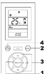
Aim the remote control at the air conditioner
1 Press the button.
2 Press the 📧 button.
The screen will switch display successively as
shown below:
COOL DRY FAN HEAT AUTO
A
set to a required mode
3 Press the temp button.
Press or button for the preferred
It can be set among 18°C\~30°C
Standard

-Press 📊 or 🏠 button cannot be set under
Fan, Dry mode operation.
• The temperature can also be adjusted in
Auto mode
4 Press the 📄 button.
Set the air flow rate as desired.
Operation condition of the air conditioner
Please use within the following operation scope, otherwise it will start the automatic protection device and resist the work of the air conditioner.
| COOL operation | HEAT operation | |
| Outdoor temperature | About 21^ to 43^ | About -15^ to 24^ |
| Indoor temperature | About 21^ to 32^ | About below 30^ |
| Indoor humidity | It is about lower than 80%. When the equipment is used in the environment with more than 80% relative humidity, the dewing phenomenon on the surface of the equipment may be caused, thus, the water drops are produced. | — |
Characteristics of HEAT mode operation
Mechanism and capacity of HEAT mode operation
- The unit draws in heat from the cold outside air, transfers it indoors and heats the room. The heating capacity of the heat pump mechanism decreases when the outside air temperature gets colder.
- The hot air circulation system takes a while before warming up the room temperature.
- If the outside temperature becomes extremely low, it would be better to use an additional source of heating.
- If the outdoor temperature is high, the indoor temperature may be higher than the setting temperature.
About fan speed
■ During the cooling or heating operation, you can select the working capacity of air
| FAN SPEED | OPERATION |
| AUTO | Automatic settings by microcomputer |
| HI | III power operation |
| MED | Standard operation |
| LO | Economic operation |
| ULO | Ultra- quart operation |
In DRY mode operation, the fixed display is breeze, which is not adjustable. The LCD screen of the remote control displays the corresponding diagram of breeze. The fan speed can also be set during SLEEP mode operation.
- Under the super-power speed operation state, press the fan speed button to exit the JET operation mode, the current state remains unchanged, and the fan speed button to the next cycle wind speed.
Air flow direction adjustment procedure
Adjusting up/down air flow direction
■ Up/down direction can be adjusted with the AIR FLOW button on the remote control. Each time when you press this button the mode changes as follows: Change on AIR FLOW (UP/DOWN) mode.

■ Left/right direction can be adjusted with the AIR FLOW button on the remote control. Each time when you press this button the mode changes as follows: Change on AIR FLOW (LEFT/RIGHT) mode.


- When heating operation starts, the outlet of the cold air will be blocked and the wind guide blade will be moved to the horizontal place. When the warm wind begins to blow, the air then will recover to the act position.
- Since the temperature indoor is higher than the set one, the compressor will stop and remain in the "defrosting" position and wind guide blade will be in the horizontal position.
- Under the circumstance above, the direction of air supply can not be set. After the warm air starts to blow, the setting of the direction of the air supply can be changed.
3D AUTO OPERATION
■ When the remote control is turned on, use the 3D AUTO air flow button on the remote control to swing the air flow up/down and left/right.
■Press the 3D AUTO air flow button again to restore the up/down and left/right air flow to the original settings. (SWING) (SWING)
MEMORY FLAP(FLAP STOPPED)
When you press the AIR FLOW (up/down/left/right) button once while the flap is operation, it stops swinging at an angle. Since this angle is memorized in the micro computer, the flap will automatically be set at this angle when the next operation is started.

- The recommended stop angle of the wind guide blade.

SLEEP operation procedure

About sleep operation
When the sleep operation mode is set, the room temperature will be automatically controlled as time goes on, and the room temperature will not be too low in cooling operation or too high in heating operation.
- In cooling operation: When the sleep operation starts, the preset room temperature will be raised. The room temperature will be adjusted automatically according to the preset temperature and the operation time, with an increase of 3 at the most.
- In the heating operation: When the sleep operation starts, the preset room temperature will be reduced, and the room temperature will be automatically adjusted according to the preset temperature and the operation time, with a decrease of at the most.
Aim the remote control at the air conditioner.
1 Press the button.
2 Press the 📄 button.
Press the SLEEP button to turn on the sleep function in the cooling and heating modes. The sleep operation state, fan speed setting, guide vane swing setting, temperature setting and timing function will not affect the sleep operation state.
Terminate sleep operation
- Press the ^14-19 button again to exit the sleep function - Press the ^16-12 button to switch the mode and exit the sleep function. - Press the ^16-10 button to exit the sleep function.
ON-TIMER operation procedure
■ Timing operation includes the setting of on-timer and off-timer. The on-timer function can be set only when the air conditioner is not running.
Example: Near set temperature around 8:00 a.m.
Aim the remove control at the air conditioner.


Change the set time Set a new time by using the button.
1 Press the 📂 button. On-timer indicator Ⓞ 800 will flash
2 Press the + or - button.
Each time ⏻ button is pressed, the indicator is switched in the order of:
→0:01→0:01 1:2→1:2→ → →(in one minutes)
Each time ⏻ button is pressed, the indicator is switched in the order of:
→1:10 →2:30 24:36 24+89→25 → →(In one minutes)
Units of ten minutes.
Set it to 8:00.
The timing diagram and figures will not flash
during the setting process, and will return to the
flashing state if the time is not adjusted for 2
seconds.
3 Press the ⏻ button again.
The display changes from blinking to steady
lighting and the setting is complete
The LCD display of the remote control shows the Figure in the power on state.
figure in the power on state
-Releasing the ON-TIMER
- During the setting process, press the button to discard the setting and exit the setting mode, and perform the shutdown at the same time. - During the setting process, there is no operation for 10 seconds, and it will automatically exit the setting and return to the original state.

- In the process of setting the on-tinner, except for the above buttons, other buttons are invalid.
OFF-TIMER operation procedure
■ Timing operation includes the setting of on-timer and off-timer. The off-timer function can be set only when the air conditioner is running.
Example: You wish it to stop at 22:00 p.m. Aim the remote control at the air conditioner.

Change the set time Set a new time by using the button.


Each time button is pressed, the indicator is switched in the order of:
→1:00 →4:52 3→38 13→91→35 → →(In one minutes)
Units of ten minutes. Set it to 20:00.
The timing diagram and figures will not flash
during the setting process, and will return to the flashing state if the time is not adjusted for 2.
shaming state if the time is not adjusted for 2 seconds.

The display changes from blinking to steady
lighting and the setting is complete. The LCD display of the remote con
the LCD display of the remote control displays the graphics in the shutdown state.
- Releasing the OFF-TIMER-
- During the setting process, press the (8.1) button to discard the setting and exit the setting mode, and perform the start up at the same time. - During the setting process, there is no operation for 10 seconds, and it will automatically exit the setting and return to the original static.

- In the process of setting the off - timer, except for the above buttons, other buttons are invalid.
-53
Setting method of the current time
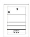
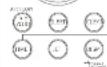
■ The current time will be set to 13:00 automatically after the battery is installed. When entering in the time setting, all the contents on the remote controller will be reset. Example: it is set to 10:00.


-2
1,3
1 Press the button. (Press continuously for 3 seconds) The time display icon /300 blinks and can be set to the current time
2 Press the + or - button.(set to 10:00)
When setting the time, press the ☑ or ☐ button to set the increase or decrease of the clock timing time. Keep pressing the ☐ button or ☐ button, and the minutes will increase or decrease in steps of "1", and the minutes will increase or decrease in steps of "10" after 3 seconds increment or decrement. The time is in 24 - hour format. If the minute is greater than or equal to 60, "1" will be automatically added to the hour. If the minute is "0", click the ☐ button, the hour will be automatically reduced by 1, and the minute will be "59".
3 Press the 18-1 button again.
The display changes from blinking to steady
current time the setting is complete. The LCD display icon “:” flashing statetate.
- Releasing the current time - During the setting process, press the button to give up the setting and exit the setting mode, and execute the power on or power off at the same time. - The setting mode is invalid except for the above buttons.
-54
三菱図番 DWG. NO. MHL DWG. NO. RYD012A378 SUFFIX PAGE 29/
JET operation procedure
■ After the JET function is turned on, the temperature will be automatically compensated on the basis of the original set temperature. The temperature range is between 18 °C \~ 30 °C. The temperature decreases by -2 °C during refrigeration and increases by 2 °C during heating.

- Releasing the JET-
- During the JET operation, press the button to exit the JET mode and switch to the next cycle mode.
- During the JET operation, press the button to exit the JET mode. The current state remains unchanged, and the air flow volume switches to the next circulating air flow volume.
- During the JET operation, press the button to exit the JET mode and execute the sleep function according to the current mode.
- During the JET operation, press the 📄 button to exit the JET mode and operate according to the economic mode. During the ECONO operation, press the 📋 button to exit the economic mode and operate in the JET mode.
ECONO operation procedure

1 Press the button. Make the air conditioner operation.
2 Press the button. During the cooling or heating operation, press the button, the economic operation mode is on and the display screen displays.
Releasing the ECONO - In ECONO operation, press the ^27 button to exit the ECONO mode. - In ECONO operation, press the ^31 button to exit the ECONO mode and execute the sleep function according to the current mode. - In ECONO operation, press the ^27 button to exit the economic mode and operate in the JET mode.
CLEAN operation procedure
About the CLEAN operation: under the COOL and DRY mode, after powering off, the fan of indoor machine will continue running for 0.5 hours to discharge the water in the machine, achieving the clean. If the indoor unit makes a "beep" sound when the CLEAN operation is in progress, it is not abnormal.

CLEAN mode setting can be carried out in the ON/OFF state. Aim the remove control at the air conditioner.
1 Press the button. Each time you press the CLEAN button, and the following changes will be shown in turn: ("CLEAN" open) ("CLEAN" closed) Not display
2 Press the button.
NOTE During the status of the "CLEAN" operation, the fan of the indoor machine will operate for 0.5 hours. During the Clean operation, the "Running" indicator flashes. During the CLEAN operation, press the CLEAN button to stop the CLEAN operation, but at the same time, the CLEAN setting will be canceled.
How to set the Child Lock
■ Child lock is set to prevent misuse, which can be made under the ON/OFF state.


Aim the remote control at the air conditioner.
Cancel the Child Lock
Under the Child Lock state, make a long press of Child Lock button for more than 3 seconds until the "disappears", indicating the Child Lock is canceled and you can make other operations.

- Under the Child Lock state, the temperature, air quantity, wind direction and other settings can't be changed, if necessary, please cancel the Child Lock.
Emergency run operation procedure
- The "ON/OFF" button on the unit operates "ON/OFF" temporarily when the remote control is not used.

- Operation is started by pressing "ON/OFF" button and press again to stop.



- Please do not keep pressing "ON/OFF" button for more than 5 seconds. (When the air conditioner is maintained or moved, COOL mode will be set automatically by keeping pressing for more than 5 seconds.)
Auto restart function after power interruption
What is the automatic restart function after power interruption? The automatic restart function after power interruption is to record the operation status of the air conditioner before power interruption and then automatically recover the operation after supplying electricity again. The following setting will be cancelled: ①Setting of the timer ②Operation of "III POWER" operation

- The air conditioner is turned off at the factory off auto-recovery function. If you need to turn on this feature, please consult a dealer. - Once electricity is recovered to supply, timer will be reset.
Remote control handing procedure
Replacing the batteries
The following cases signify exhausted batteries.replace old batteries with new ones.
- Receiving beep is not emitted when a signal is transmitted.
• Indicator fades away.
1 Remove back lid and
3 Close the hack cover
2 Insert new batteries. (AAA battery)

4 Make a long press of TIMER button for more than 3 seconds. Setting mode of the d- isplay time.

- Don't use old and new batteries together.
- Remove the batteries when the remote control is not used for a long period.
• The life of a battery conforming to JIS or
IEC is 6 to 12 months with normal use. If
used longer, or when an unspecified batt-
ery is used, liquid may leak from the bat-
ery, causing the remote control to maintenance
C2014.
- On the battery is printed its expected life. This may be shorter than that of the battery, depending on the date of manufacture. - However, the battery may still be in working order after expiry of its nominal life. - The old batteries must be well done.
Waring note for remote control handing
- Don't go near high temperature places, such as an electric carpet or stove.
- * Don't leave the remote control exposed to direct sunlight or other strong lighting. * Don't drop the remote control. Handle with care.

- Don't put any obstructing obstacles between the remote control and the unit.
- Don't spill water etc on the remote control. - Don't put any weight on the remote control.


When the operation fails with the remote control
- Are the batteries running down? Replace the batteries with new ones and repeat the operation. - If the operation still fails, handle as per Page58 emergency run operation. Contact your dealer.
Operating hints
■ Please observe the following for the most economic and comfortable use of your unit.
Set a suitable room temperature.
Clean the filters frequently.
Avoid direct sunlight and draught.
Excessively high or low temperatures are not good for your health and waste electricity.
Clogged filters may block the air flow and cause less efficient operation.
Cut out direct sunlight by drawing the curtains or blinds when cooling keep windows and doors shut, except when ventilating.
Adjust the airflow direction properly.
Operate the unit only when needed.
Generate little heat when cooling.
Adjust the up/down and left/right airflow to ensure a steady room temperature
Use the timer properly to operate the unit only when needed.
Keep heat sources out of the room as much as possible.
Maintenance
| Before maintenance | During the operational season |
| Turn off the power switch. | Cleaning the air filter Standard interval is once every two week.1 Remove the air filter |
| Don't spill water.Wipe the unit with a soft dry cloth.Never contact with the alumina-tum fin on the air hear exchanger.When unloading the inspiration grid and filter screen, stand on the stepladder or other stable objects firmly. | 2 CleaningIf the filter is very dirty, clean it with warm water tapprox. 30°C, land dry it thoroughly.CAUTIONDon't clean the filters with boiling water.Don't dry them over an open flamePull them out gently. |
| Don't use the following articles:Hot water (40°C or more)Petrol, paint thicker, benzine or polishing agents, etc.They may deform or scratch the unit. | 3 Reinstall the air filterHolding firmly the filter at both sides as shown at right and rest securely.Operating without putting back the air filters will make the unit dusty, and may cause damage. |
| Cleaning the unitWipe the unit with a soft, dry cloth, or use a vacuum cleaner.If the unit is very dirty, wipe it with a cloth soaked in warm water. | |
| Cleaning the air inlet panelUnloading, loading and installing the inlet panel.Piped can be washed by water. Wipe the water on the panel and dry it after washing. |
At the end of the season
| 1 | Set the temperature setting for approximately a half day at 30°C andperform the cooling operation.Dry the inside of the unit. |
| 2 | Stop the unit and turn off the power switch.The unit uses app: 3W over when the power switch has been turned off during theoff season for saving energy. |
| 3 | Clean and reinstall the air filters. |
| 4 | Clean both the indoor and outdoor units. |
| 5 | Remove batteries from the remote control. |
At the beginning of the season
| 1 | Make certain that there are no obstacles blocking the air flow around the air intake and outlet openings of the indoor and outdoor units. |
| 2 | Check the installation base for corrosion or tunst. |
| 3 | Ensure that nothing has snapped and that the earthed flex is not disconnected. |
| 4 | Ensure that the air filters are clean. |
| 5 | Turn on the power switch. |
| 6 | Insert batteries in the remote control. |
Installation, inspection and change of the filter screen
How to open the air Inlet panel
Place figers at the recesses on both sides of the panel and pull up the panel to this side so that it will be opened by about 60 degrees.
How to close the air Inlet panel
Push both sides evenly and press further lightly at the center.

Removal, Installation of air inlet panel
When removing the air inlet panel for internal cleaning or others, open the panel by 65 degrees and then pull it to this side. Secure either the upper or lower edge of the air inlet panel by lightly pushing it in, and then close the panel.


Installation of the filter screen
- Open the inspiration grid and unload the air filter screen.
- The filter screen is fixed within the fixation and the
filter screen fixation is installed within the air conditioner. 3. Install the air filter screen and close the inspiration grid.

The filter screen is installed on the right and left side of the u conditioner.
Air filter screen


Inspection and change of the filter screen
Inspection and change of the filter screen. In
1.Open the inspiration grid and change the filter screen.
2.Unload the filter screen from the filter screen fixation and then inspect it.The vacuum dust catcher is adopted to clear the dust filth in the filter screen.If the filter screen is unable to be clean or used for one year, it needs changing. The filter screen needs changing after using for near one year but the actual change period will be different according to the application environment.
3.Install the filter screen within the fixation and then install the fixation within the air conditioner.
4. Install the air filter screen and close the inspiration grid. Please contact with the distributor when changing the filter screen.
| Item | Feature |
| Lysozyme filter screen | The moldy and bacteria on the filter screen can be destroyed means of the lysozyme and the oxidation to make the air indoor clean and tidy. |
Installation, inspection and change of the filter screen

- The air filters clogged with dust, etc., then the cooling / heating capacity will drop, the operation noise increases, power consumption also increases. Therefore, the air filter should be cleaned periodically. - Before removing the filter, be sure to turn off the air conditioner off.
The following situation is not a failure
| You cannot restart the unit immediately after you have stopped it. RUN light is on) | -Restarting has been blocked for 3 minute after you have stopped, to protect the unit |
| [The three minutes protection turner in the macrocomputer auto automatically starts up again. This function is not activated] you have disconnected the power. | |
| Air supply is not carried out when heating is started. Operation pilot lamp flashes slowly (1.5 seconds for light use 0.5 second for dark) | Before the indoor heat exchanger becomes warm, air supply will be stopped to prevent that the cold air is sent (2-5 minutes). (Heat maintenance) |
| During the process of the refrigeration operation,air is not blown for 5-10 minutes or what blows is not the warm air. Operation pilot lamp flashes slowly (1.5 seconds for light use 0.5 second for dark) | When the outdoor temperature is too low and the humidity is relatively high, the air conditioner will carry out defrosting operation automatically and please wait patiently. After defrosting, water or steam will be disappear from the outdoor machine. (2-5 minutes) |
| Air is not blown out when starting the DRY operation. (RUN light is on) | The indoor fan may stop to prevent reevaporation of dehumified moisture and to save energy. |
| Some steam escapes during COOL operation. | This may occur if the room's temperature and humidity midtry are very high. It disappears as soon as the temperature and humidity decrease. |
| There is a slight smell. | Air blown out during operation may smell. This is caused by tobacco or cosmetics sticking to the unit. |
| You hear a slight gurgling sound. | This is caused by refrigerating liquid moving within the unit. |
| You hear a slight cracking sound. | This is caused by heat expansion or contractio |
| "si-si" or "ka-da" sound may be issued | This owns to the operation of the refrigerant control valve or the electric components |
The following situation is not a failure
| After a power cut, you cannot restart, even if power has been restored. | The memory circuit of the microcomputer has been wiped out. Use the remote control to start the operation again. |
| Remote control signals are not received. | Remote control signals may not be received if the signal receiver on the air conditioner is exposed to direct sunlight or other bright light. If so, cut out the sunlight or reduce the other light. |
| Moisture may form on the air outlet grilles. | If the unit is operated for a long time in high humidity, moisture may form on the air outlet grilles and start dripping. |
| The interruption noise of the outdoor machine can be heard. | The noise is the speed acceleration of the compressor. |
| The fan does not stop immediately when the air conditioner stops operation. | Indoor fan: when the mildew-proof operation is set, fan will not stop within 0.5 hours. Outdoor fan: the fan will not step within one minute in order to protect the air conditioner. |
| The operation pilot lamp is still on after the operation is finished. | The operation pilot lamp will be off when the mildew-proof operation is finished. |
When to contact your distributor without delay
| The fuse or switch blows continuously. | The cable becomes extremely hot.CAUTIONIf the insulation layer of the power line is damaged, in order to avoid accident, please contact with your distributor or professional engineer to change it. | |
| The TV, radio or other equip ment starts to malfunction. | A switch does not activate properly. | You hear a strange noise during operation. |
| When faulty movement is observed when the ON/OFF | The RUN and TIMER lights on the unit indication section brink quickly (0.5 sec. ON, 0.5 sec. OFF) and don't work. | |
Has the unit been installed correctly?
Suitable installation position
- Is there any obstruction in front of the indoor unit, preventing porper ventilation and functioning?
- Don't install the unit in any of the following places:
- Where there is a danger of leaking inflammable gases.
- Where there is substantial splashing of oil.
•Malfunctioning due to corrosion may occur if the unit is installed in a two-where sulfate
- Matrification due to correction may occur in the site is assumed in a spot where sa
gises are generated of in a seaside resort exposed to sea breezes. Contact your dealer.
- The air conditioner and remote control must be at least 1 metre away from a 1 - Drain the dehumidified liquid from the indoor unit into a spot that drains well.
Pay attention to operating noises
- When you install the unit, take care to choose a place that can comfortably stand the weight of the unit and does not increase the operating noise or vibration. If there is any likelihood that vibration may be transmitted through the house, fix the unit with the aid of vibration proof pads between the unit and the fittings. - Select a place where cold or hot air and operation noises from the indoor and outdoor units do not cause any inconvenience to your neighbors. - Not leave any obstacles near the outlet and ink of the outdoor unit. This may cause fluctuations and increased operating noise. - If you hear an irregular noise during operation, contact your dealer.
Inspection and maintenance
Dependent upon service conditions and operating environment, the inside of the air conditioner may become dirty after a number of season's service (3 to 5 years). This will reduce performance. In addition to normal cleaning, we would recommend inspection and maintenance. (The air conditioner has a longer life without any trouble.)
* Contact your dealer, or any distributor, for inspection and maintenance. (There will be a charge for this service).
• We would recommend inspection and maintenance to be carried out during the off season.
- If the supply cord of this appliance is damaged, it must only be replaced by a repair shop appointed by the manufacturer, because special purpose tools are required.
Troubleshooting
Please carry out the following checks before making a service call.
| The air conditioner does not work at all | ||
| Has the power switch been turned off? | Has the timer been set in the "On" position? | Is there a power failure of a blown fuse? |
| Insufficient cold air or warm air | ||
| Have you set the thermostat at a suitable temperature? | Is the air filter clean?(Not clogged?) | Did you leave any doors or windows open? |
| Insufficient cold air | ||
| Is there any direct sun-light entering the room? | Is there a heat source in the room? | Are there too many people in the room? |
If the air conditioner does not operate properly after you have checked the above points or if any doubt still exists after you have consulted page64, or if things happen as shown on page 65, switch off the power and contact your dealer.
Self diagnosis function
The company always strives to provide the clients with more excellent service and install different judgment systems to display the following abnormal functions (the ones for abnormal lighting and quenching type are illustrated as follows. The values in the table represent the times for lighting and quenching within 8 seconds. The type is 0.5 second for lighting and 0.5 second for quenching):
| Abnormality content | Error code | ||
| Indoor unit | Sensor | Indoor heat exchange temperature | 06 |
| Indoor heat exchange temperature sensor abnormal | 07 | ||
| Miscellaneous | Indoor fan motor abnormal | 16 | |
| Indoor and outdoor communication abnormal | 05 | ||
| Indoor EEPROM failure | 61 | ||
| Outdoor unit | Sensor | Outdoor heat exchange temperature sensor abnormal | 37 |
| Outdoor ambient temperature sensor abnormal | 38 | ||
| Outdoor exhaust temperature sensor abnormal | 39 | ||
| Miscellaneous | Supply voltage overvoltage or undervoltage | 47 | |
| Outdoor fan motor abnormal | 48 | ||
| Outdoor unit failure / compressor pour starting | 59 | ||
| Compressor locked rotor | 60 |
Sheet, installation
| Installation tool (necessary) | Accessories list | ||||
| 1 | Crosshead screwdriver | No. | Parts name | Quantity | Place for storage |
| 2 | Knife | 1 | Indoor body | 1 | Indoor Packing |
| 3 | Saw | 2 | Installation board (attached behind the indoor door) | 1 | .. |
| 4 | Tip | 3 | Self-typing screw (used for installation board) | 5 | .. |
| 5 | Hammer | 4 | Battery (R03 L.SV) | 2 | .. |
| 6 | Wrench | 5 | Instruction for application and installation | 1 | .. |
| 7 | Torque wrench 14.0-62.0N.m (1.4-6.2kgf.m) | 6 | Remote control | 1 | .. |
| 8 | Hollow drill (65mm diameter) | 7 | Filter assy | 1 | .. |
| 9 | Hexagon wrench (hexagon) [4mm] | 8 | Outdoor body | 1 | Outdoor Packing |
| 10 | Vacuum pump | 9 | Drain elbow | 1 | .. |
| 11 | Adaptor of the vacuum pump (anti-backward (low type) professional for R410A) | 10 | Water shutoff plug | 1 | .. |
| 12 | Pressure gauge group ( professional R410A) | ||||
| 13 | Charging hose (professional for R410A) | ||||
| 14 | Flaring tools (professional for R410A) | ||||
| 15 | Leak detector (professional for R410A) | ||||
| 16 | Adjustment regulation of the horn port (used when the common flaring tools are adopted for tube expanding) | ||||
Points for attention for installation
○ The system is applied to the household, resident and other places.
○ The equipment must be installed subject to the national routing regulation.
○ The fixed routing of the power adopts the grade 2 switch and the disconnection
spacing shall be 3mm at least.
When the outdoor machine probably falls down or moves, or falls from the original installation place, the following operation is adapted to fly it.
original installation place, the fastening screw or wire is adopted to fix it.
○ The liquid level pipe and gas pipe in the pipe must need the heat isolation
materials for insulation treatment.
Safety precautions
- Please read these "safety Precautions" first then accurately execute the installation work.
- Though the precautionary points indicated herein are divided under two headWARNING andCAUTION those points which are related to the strong possibility of an installation done in error resulting in or serious injury are listed in theWARNING section. However, there is also a possibility of serious consequences in relationship to the points listedCAUTION section as well. Neither case, important safety related information is indicated, so by all means properly observe all that is mentioned.
- After completing the installation, along with confirming that no abnormalities were seen from the operation tests, please explain operating methods as well as maintenance methods to the user (customer) of this equipment, based on the owner's manual. Moreover, ask the customer to keep this sheet together with the owner's manual.
WARNING
- To disconnect the appliance from the mains supply this appliance must be connected to the mains by means of a circuit breaker or a switch with a contact separation of at least 3mm.
- The appliance shall be installed in accordance with national wiring regulations. - This system should be applied to places as households, residences and the like. Application to inferior environment such as engineering shop could cause equipment malfunction.
- Please enirust installation to either the company which sold you the equipment or in a professional contractor. Defects from improper installations can be the cause of water leakage, electric shocks and fires.
- Execute the installation accurately, based on following the installation manual. Again, improper installations can result in water leakage, electric shocks and fires.
- For installation, confirm that the installation site can sufficiently support heavy weight. When strength is insufficient, injury can result from a falling of the uni
- For electrical work, please see that a licensed electrician executes the work while following the safety standards related to electrical equipment, and local regulations as well as the installation instructions, and that only exclusive use circuits are used. Insufficient power source circuit capacity and defective installment execution can be the cause of electric shocks and
- Accurately connect wiring using the proper cable, and insure that the force of the cable is not conducted to the terminal connection part, through properly securing it improves connection or securing can result in heat generation or fire.
• Take care that wiring does not rise upward, and accurately install the lid/service panel. It's improper installation can also result in heat generation or fire.
- When installing or moving the air conditioner, never mix any other refrigerant except air and the regulated refrigerate(R410A) to the refrigeration circulation system, otherwise damage, personal injury, and other accident may be caused, due to the abnormal high pressure
- Please adopt the matched or appointed parts for installation, otherwise water leakage, electricity leakage, fire, the leakage of the refrigerant and other accident may be incurred.
- If the phenomenon such as the leakage of the refrigerant occurs when the installation work is carried out, please adopt the ventilation measures immediately, otherwise harmful gas may be generated when the refrigerant contacts with the fire.
- Please make sure that no leakage of the refrigerant phenomenon incurs after installation work is finished. If the refrigerant leaksi indoors and contacts with the air supply (type warmer, furnace and other fire source, harmful gas is probably generated.
CAUTION
- Execute proper grounding. Do not connect the ground wire to a gas pipe, water pipe, ning rod or a telephone ground wire. Improper placement of ground wires can result in electric shock.
- The installation of an earth leakage breaker is necessary depending on the established location of the wait. No installing an earth leakage breaker may result in electric shock
- Location of the unit, No instaining an earth leakage breaker may result in electric shock. - Do not install the unit, where there is a concern about leakage of combustible gas. The rare even of leaked gas collecting around the unit could result in an outbreak of fire.
CAUTION
- For the drain pipe, follow the installation manual to insure that it allows proper drainage and thermally insulate it to prevent condensation.
- Inadequate plumbing can result in water leakage and water damage to interior items. Install the outdoor unit so that the aluminum fins on the air heat exchanger cannot be touched. Failure to observe this may result in injury.
- Do not place objects near the outdoor unit or allow leaves to gather around the unit. If there are objects or leaves around the outdoor unit, small animals may enter unit and contact electrical parts resulting in break down, emission of smoke or flame.
Handling matters needing attention
- Handling machine, be sure to be particularly careful when the weight of the machine to reach 20 kg or more, the need for two or more. Before they can carry. Don't scratch the packing bag. When you need to remove or move the machine in the packaging bag, be sure to wear it. Protective gloves, because the heat sink or other parts may be caused by the injury and other parts of the injury accident.
- Please handle packing material. Nails and other metal or wooden parts and other packaging materials may cause injury, hurt etc.
Installation Preparation
Prior to installation, please check whether the power supply is matched with the air conditioner. This power supply must be a dedicated circuit power supply.
On the line of the machine should be equipped with leakage protector, and every air conditioner must use a dedicated power supply branch line. Power supply, on the branch line should be equipped with the corresponding circuit breakers, the corresponding specifications are shown in the following table:
| Model | Connect wiring specification | Power cable specification | Rated current |
| SRK25QE3 | YZW 300/500V 4×1.0mm ^2 | H05VV-F300/500V 3×1.0mm ^2 | 16A |
| SRK35QE3 | |||
| Color | White | ||
Drainage pipeline
○ Install the drainage hose in the lower angle. ○ The lower drainage pipe shall be provided


ON After undergoing all the procedures, start to inspect whether the drainage is proper, otherwise, water leakage may be incurred.


Higher than the regulated one The tip of the drainage house is within the water
Higher than the regulated one The tip of the drainage house is within the water
○ Pour water to the drainage disk under the heat exchanger to guarantee that the water has discharged outside the room
When the prolonged drainage hose is within the room, the shield pipe (user installation) must be used to ensure the thermal insulation.
Shield pipe
Drainage hose Being naked within the room Prolonged drainage hose
Select the installation place
Indoor machine
○ The warm and cold wind can be sent to anywhere without the obstacles to prevent.
○ The fruiting place that the indoor machine or wall will not vibrate.
○ The place with sufficient maintenance space (the space mentioned below is safe).
○ The place where facilitates the installation of wiring and pipe.
○ The place where the parts will not suffer from direct sunshine or strong light irradiation.
○ The place with easy drainage of the equipment.
○ 1 meter shall be left from the TV or radio (otherwise it may interrupt the image of TV or produce noises).
Outdoor machine
○ The place where is rain and snow proof and without direct irradiation of the sunshine.
○ The place where the wind and noise produced will not influence the neighbors.
○ The place where the installation and repair condition is allowed
※ It shall avoid installing in the following pla-
○ The place near the bedroom to avoid trouble due to the operation noise.
○ The place where exists the leakage of the combustible gas.
○ The place where suffers from the strong wind.

Select the installation place
- The exhaust port and inspiration port behind the equipment shall be installed 10cm far away from the wall. (If the height of the feace is higher than 1.2m ar above the head, sufficient space shall be left between the equipment and the wall) - The following sizes shall be guaranteed after the installation of the equipment.

CAUTION
If the wall is more than 1.2m high or the ceiling is possessed, it shall be 1-arger than the size labeled above.
How to unload and install the front panel
○ Unloading
① Unload the inspiration grid ② Unload 2 screws fixing the front panel.
③ Unload 3 lock bars in the lower part of the front panel and then unload the front panel from the equipment.
① Unload the air filter screen. ② Cover the equipment by front panel cover.
③ Fasten 2 screws and fix the front panel. ④ Install the air filter screen. ⑤ Install the inspiration grid.

Installation of the indoor unit
Installation of installation board
Fix the installation board
Find the stent, small column and other structural parts of the wall first install and filx more firmly after making ensure whether the installation place is horizontal.
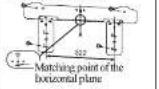
○ Four screws are used to horizontally adjust the installation board when it is under the temporary fastening status.

○ Center on the standard hole to rotate the installation board to make it horizontal.
Set the relationship between the
board and indoor machine
798 100
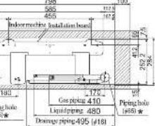
* The center of circle levels with cement line of installation board
Fix on the concrete wall
| Using nut fixer Using screw fixer | Using nut fixer Using screw fixer |
Installation of the indoor equipment
Fixation of the drilling and sleeve (optional parts)
Ø 65 core drill is used for drilling

The core drill is used for drilling
Install the sleeve

○ Insert the sleeve
Schematic diagram of the status after installation

Adjust the length of the sleeve

○ If the back piping is pulled out, cut the lower part and right side of the axis circulation.
Sleeve Inclined board Sealed ring

CAUTION
Drill a hole with 5° inclined angle for indoor to outdoor
Installation preparation of the indoor machine
Installation preparation of the wire connection
① Open the inspiration grid.
② Unload the cover.
③ Open the wire clamp
④ Connect the wire to the connection board firmly.
1) Connect the wire to the connection board firmly. If the wire has not fixed well, it may cause power connection and danger, since the connection board may produce heat and cause fire.
2) Never get confused about the quantity of the terminals of the indoor and outdoor connections.
⑤The wire clamp is used to connect the wire. ⑥Fix the cover.
⑦ Close the inspiration grid.

CAUTION
If the routing connection encounters some faults, the indoor machine will stop operation, the operation lamp will be on and the timer lamp will flash.
Install the piping stent
Shaping the pipe

○ Hold the root of the piping and carry out shaping to the prolonged part after pulling out of the pipe.
- Points for attention when connecting to the left and the center [Top view]

Taping of the exterior ○ Tape only the portion that runs through the wall. Always tape the crossover wires with the pipe. ○ The routing must be winded together with the external insulation belt. ○ Start from the lower part of the piping when bandaging the insulation belt to avoid the invasion of the rainfall.
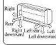
Piping is possible in the rear, left, left rear, left downward, right or downward direction.
Fixation of the indoor machine
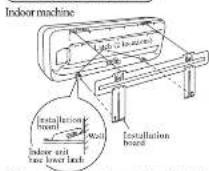
● How to remove the indoor unit from the installation
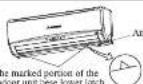
① Push up at the marked portion of the indoor unit base lower latch, and slightly pull it toward you. (both right and left hand sides)
(The indoor unit base lower latch can be removed
from the installation board)
3) Push up the indoor unit upward. So the indoor unit will be returned from the installation board.
- When the internal machine is fixed, the mounting surface of the base shall be completely covered on it wall or other fixed objects, without semi-suspension.
Installing steps
① Hook the upper part of the indoor unit to the installation board.
② The unit can be installed simply by gently pushing in the lower part.

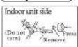
There is the drainage disk established for collecting dew at the back side of the air conditioner and please do not place power line on the drainage disk.

Installation of the outdoor machine
Please make sure the place where the outdoor machine is installed is fixed first and then installation can be carried out.
When installed in a place with a relatively high position or easily suffer from invasion of the strong wind, please adopt the anchor bolt, wire and others to fix the machine firmly.
○ Connection can be carried out after making sure that the number of the connection terminal complies with that of the indoor machine.
- Please adopt the foot pen near mark for connection. - When the temperature is lowered below 0°C, never install the drainage elbow.


Connecting line between indoor unit and outdoor unit colour rubber
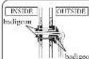
WARNING
Please use haligeon to completely seal the hole in the wall. If the seal is not tight, dust, insects, small animals and high humidity air may enter the room from the outside, and thus cause fire or other risk accidents.
NOTE
Please use hadigeon to completely seal the hole in the wall. If the seal is not tight, it may cause furniture and other equipment to be damaged by the condensate dripped from the air conditioner.
Piping connection
Preparation Keep the operation of the pipes covered with tapes etc. to prevent dust, sand etc. from entering them.

Remove the flared cuts (on both liquid and gas sides)

Size A
Liquid part: Ø9.1 (mm)
Gas part: 25-35 type: Ø13.2

| MODEL | Size B(mm) | ||
| R410A close typeflaring tools | Common (R22) flaring tools | ||
| Close type | Actial nut type | ||
| #6.36 | 0.0~0.5 | 1.0~1.5 | 1.5~2.0 |
| #9.52 | 0.0~0.5 | 1.0~1.5 | 1.5~2.0 |
Please notice, when using R410A professional flaring too or common flaring tool, that size B (from the outstanding part of the flaring board) will change which is determined by the type of the flaring tools. If the common flaring tool is used, please use the copper pipe gauge or the similar instrument spect to make size B maintain the proper value.
- Flaring operation

Block Copperpipe
CAUTION
Do not use the excessively large torque on the flaring nut, otherwise the flaring nut may break and the refrigerant may leak.
Connection
Indoor

Outdoor
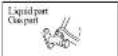
○ The liquid part and gas part connect at the
same time
The fastening torque is as follows at this time: Liquid part (Φ6.35):14.0–18.0N·m(1.4–1.8kgf·m) Gas part (Φ9.52):34.0–42.0N·m(3.4–4.2kgf·m)
○The liquid part and gas part connect at the same time. ○All the torques are the same with the indoor.
Air purge
① Tighten all flare nuts in the pipings both indoor and outside wall or not to wear back.
②Connect service valve, charge hose, manifold
valve and vacuum pump as is illustrated below
③Open manifold valve handle 1.0 to its full witch,
and perform vacuum or evacuation. Continue the
vacuum of evacuation operation for 15 minutes or more and check to see that the vacuum gauge
④After completing vacuum operation, fully open service valve (Both gas and liquid solids) with
hexagon headed wrench.
⑤ Detach the charge hoses.
• The diameter of the maintenance part of the machine is different from the common type, therefore, the acration hose (R22) used currently will not be used. Please adopt the R410A professional hose.
- Please utilize the vacuum pump converter of the anti-backflow type to prevent the oil of the vacuum pump from refluxing the machine. If so, the fault of the refrigeration circulation may be caused.
Limit of the size and length of the piping
| 25type | 35type | |
| Liquid piping (mm) | 6.35 × 0.8 | 4.35 × 0.8 |
| Gas piping(mm) | 9.52 × 0.8 | 9.52 × 0.8 |
| Length of largest piping | 25-35type |
| within15m | |
| Difference of the vertical height | within 5m |
| Adding refrigerant | no need |

Installation of the connection part
Post-treatment and fixation
The insulator is used to wind the conne or and then cover adhesive tape on it.


Earthing work
- Earth work shall be carried out without full in order to prevent electric shock and noise generation.
The connection of the earth cable to the following substances causes dangerous failures, the fore it shall never be done (City water pipe, Town gas pipe, TV antenna, lightning conductor, telephone line, etc.)
Moving or unloading the machine
The set processing of the pump shall be carried out in order to reach the requirements of the environmental protection (recycle the refrigerant).
The function of the set processing of the pump is to make the refrigerant in the indoor machine return to the outdoor machine when the host gets the piping. (Method of the set processing of the pump)
① Connect the aeration pipe to the maintenance
②Liquid part: The hexagon wrench is adopted to close the liquid valve.
Gas part: Open the gas valve totally.
The refrigeration operation is carried out (if the temperature within the room is too low, strengthening cooling is carried out).
⑧When the pressure gauge reaches 0.01 Mpa, stop refrigeration operation and close the gas valve.
Safe deal with the product after the life period
• The safety and comfort life period of the product is ten years.
- Some products also can be used after the life period.
- After the life period, deal of the rejectments, must consider the effect of the safety and the environment.
Repeal Notes
Dismontle air conditioners, when dealing with the refrigerant, refrigeration oil and final processing components, you must follow the relevant local and national regulations.
Inspection point of the installation test
After the installation is finished, start up the machine for trail run after inspecting and making sure the following items to make the machine operate normally. Meanwhile, explain the related affairs about the application and maintenance of the machine to the user according to the fishing
After installation
☐ The power belongs to the rated voltage
☐ There is no gas leakage in the connection part of the action valve
☐ The power line and over line shall be connected to the connection board firmly.
☐ The survey of the lid is attributed securely
- The screw of the lid is tightened securely.
- Open all the action valves.
- The heat insulation treatment has been handled in the connection part of the piping both the indoor machine and outdoor machine.
The machine will span 3 minutes to stop operation after restarting or changing the operation mode, which aims to protection the machine and does not belong to the machine faults.
Trail run
□ The operation of the air conditioner is normal.
□ No abnormal noise.
No abnormal noise
Smooth drainage.
□ The protection function does not work.
Normal operation of the remote control.
The operation affairs has been explained to the user (protection timer will be restored in 3 minutes).


- 目录
- 關於睡眠運行
- Safety precautions
- INSTALLATION PRECAUTIONS
- △ DANGER
- CAUTION
- OPERATION PRECAUTIONS
- DANGER
- PRECAUTIONS FOR TRANSFER OR REPAIRS
- △ CAUTION
- Choice of operations and features
- Characteristics of HEAT mode operation
- Mechanism and capacity of HEAT mode operation
- Press the button.
- Press the 📂 button.
- To stop
- Press the 📧 button.
- Press the temp button.
- Press the 📄 button.
- Air flow direction adjustment procedure
- Adjusting up/down air flow direction
- 3D AUTO OPERATION
- MEMORY FLAP(FLAP STOPPED)
- SLEEP operation procedure
- About sleep operation
- Press the 📄 button.
- Terminate sleep operation
- ON-TIMER operation procedure
- Press the 📂 button. On-timer indicator Ⓞ 800 will flash
- Press the + or - button.
- Press the ⏻ button again.
- -Releasing the ON-TIMER
- OFF-TIMER operation procedure
- - Releasing the OFF-TIMER-
- Setting method of the current time
- Press the + or - button.(set to 10:00)
- Press the 18-1 button again.
- JET operation procedure
- - Releasing the JET-
- ECONO operation procedure
- CLEAN operation procedure
- How to set the Child Lock
- Cancel the Child Lock
- Emergency run operation procedure
- Auto restart function after power interruption
- Remote control handing procedure
- Replacing the batteries
- Waring note for remote control handing
- When the operation fails with the remote control
- Operating hints
- Installation, inspection and change of the filter screen
- How to open the air Inlet panel
- How to close the air Inlet panel
- Removal, Installation of air inlet panel
- Installation of the filter screen
- Inspection and change of the filter screen
- Has the unit been installed correctly?
- Suitable installation position
- Pay attention to operating noises
- Inspection and maintenance
- Points for attention for installation
- WARNING
- Handling matters needing attention
- Installation Preparation
- Drainage pipeline
- Select the installation place
- Indoor machine
- Outdoor machine
- How to unload and install the front panel
- Installation of the indoor unit
- Installation of installation board
- Fix the installation board
- Set the relationship between the
- board and indoor machine
- Fix on the concrete wall
- Installation of the indoor equipment
- Fixation of the drilling and sleeve (optional parts)
- Installation preparation of the indoor machine
- Installation preparation of the wire connection
- Install the piping stent
- Installation of the outdoor machine
- Piping connection
- Connection
- Indoor
- Outdoor
- Air purge
- Installation of the connection part
- Post-treatment and fixation
- Earthing work
- Moving or unloading the machine
- Safe deal with the product after the life period
- Repeal Notes
- Inspection point of the installation test
- After installation
- Trail run
Brand : MITSUBISHI
Model : SRK25QE3
Category : Measurement