
SRK50RE1 - Measurement MITSUBISHI - Free user manual and instructions
Find the device manual for free SRK50RE1 MITSUBISHI in PDF.


| Product Type | Split System Air Conditioner (Indoor + Outdoor) |
| Model | SRK50RE1 |
| Brand | Mitsubishi Heavy Industries |
| Refrigerant | R410A |
| Cooling Capacity | Approx. 5.0 kW (17000 BTU/h) |
| Power Supply | 230 V / 50 Hz / Single Phase |
| Indoor Unit Dimensions (W x H x D) | Approx. 798 x 290 x 230 mm |
| Outdoor Unit Dimensions (W x H x D) | Approx. 780 x 290 x 230 mm |
| Indoor Unit Weight | Approx. 9.5 kg |
| Outdoor Unit Weight | Approx. 34 kg |
| Operating Modes | COOL, DRY, HEAT (if heat pump), FAN, SLEEP |
| Timers | ON Timer, OFF Timer, SLEEP Timer, Procedure Timer |
| Special Features | HI POWER / JET mode, Wind flow adjustment (vertical & horizontal), Memory wind-guiding blades, Comfortable air-supply mode, Auto restart after power interruption, Self-diagnosis function |
| Remote Control | Wireless infrared, with LCD display and buttons for all functions |
| Filter Type | Washable mesh filter (clean every 2 weeks) |
| Maintenance | Clean air filter with water; do not use solvents. Vacuum or wash gently. |
| Safety Features | Overheat protection, current overload protection, high-pressure protection, compressor protection, fan rotor failure detection |
| Installation Requirements | Must be installed by qualified professional. Use flare connections, vacuum pump, and proper torque specifications. |
| Included Accessories | Remote control, batteries (R03 1.5V), installation board, screws, drain hose, instruction manual |
| Environmental Note | Uses R410A refrigerant (environmentally friendly); dispose properly at end of life. |
Frequently Asked Questions - SRK50RE1 MITSUBISHI
User questions about SRK50RE1 MITSUBISHI
0 question about this device. Answer the ones you know or ask your own.
Ask a new question about this device
Download the instructions for your Measurement in PDF format for free! Find your manual SRK50RE1 - MITSUBISHI and take your electronic device back in hand. On this page are published all the documents necessary for the use of your device. SRK50RE1 by MITSUBISHI.
USER MANUAL SRK50RE1 MITSUBISHI

| 三菱図番 | SUFFIX | PAGE2/ |

| 三菱図番 | SUFFIX | PAGE 3/ |

![graph TD A["Start"] --> B{Decision} B -->|Yes| C["Warning: △"] B -->|No| D["Warning: ●"] C --> E["Warning: !"] D --> F["Warning: ●"] E --> G["End"] F --> G style A fill:#f9f,stroke:#333 style G fill:#bbf,stroke:#333](/content/2026/05/1043736/images/893b3c32c241ccdf98a7912321874ecf640f196b948a1c4cd8284125787bcbf8.jpg)
| 三菱図番 | SUFFIX | PAGE | |
| 4/ |


| 三菱図番 | SUFFIX | PAGE5/ |


| 三菱図番 | SUFFIX | PAGE6/ |
△
![graph TD A[" "] --> B[" "] B --> C[" "] C --> D[" "]](/content/2026/05/1043736/images/67e1f4713538cf0f6390fae13e152fc64661eacfa884f76ec9b3aeb7b5d690ee.jpg)
| 三菱図番 | SUFFIX | PAGE 7/ |
![graph TD A["1 ON OFF"] --> B["2 ON OFF"] B --> C["3 ON OFF"] C --> D["4 ON OFF"] D --> E["5 ON OFF"] E --> F["6 ON OFF"] F --> G["7 ON OFF"] G --> H["8 ON OFF"] H --> I["9 ON OFF"] I --> J["警告"]](/content/2026/05/1043736/images/a731bb0baa87607ba31921842c9f80f90b25f62794bf020b9e90cc58e5b525ba.jpg)
| 三菱図番 | SUFFIX | PAGE8/ |


| 三菱図番 | SUFFIX | PAGE9/ |


| 三菱図番 | SUFFIX | PAGE10/ |

| 三菱図番 | SUFFIX | PAGE11/ |

| 三菱図番 | SUFFIX | PAGE |

| 三菱図番 | SUFFIX | PAGE |

| 三菱図番 | SUFFIX | PAGE |


| 三菱図番 | SUFFIX | PAGE |

| 三菱図番 | SUFFIX | PAGE/ |


| 三菱図番 | SUFFIX | PAGE |


| 三菱図番 | SUFFIX | PAGE |

△

| 三菱図番 | SUFFIX | PAGE/ |
Thank you for purchasing a Mitsubishi Daiya Air Conditioner! To get the best long-lasting performance, read and follow this User's Manual carefully before using your air conditioner. After reading, please store the Manual in a safe place and refer to it for operational questions or in the event of any irregularities.
The air conditioner has utilized the new environmental protection refrigerant (R410A). Please explain the situation to the seller when service, inspection and maintenance intend to be achieved from them.
The air conditioner is applied to homes.
RYD012A352
Contents
Safety precautions
Choice of operations and features
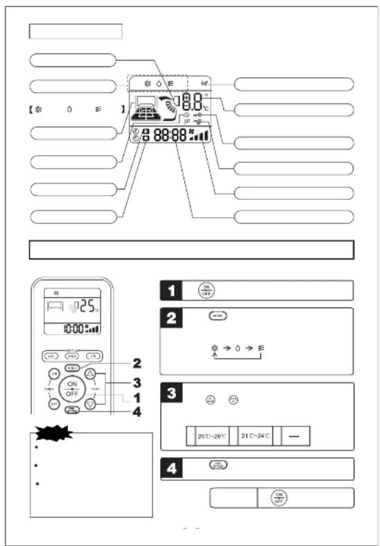
Name of each part and its function
Operation and indication section for remote control
Operation condition of the air conditioner
Air flow direction adjustment procedure
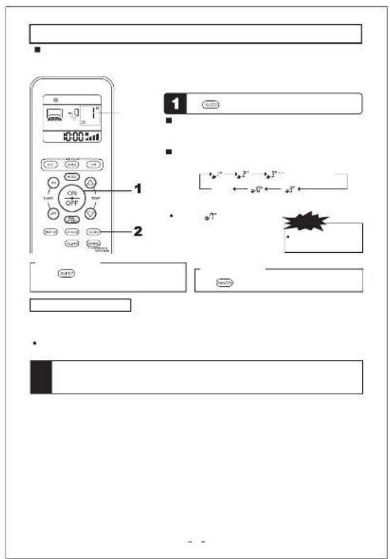
SLEEP operation procedure
ON-TIMER operation procedure
OFF TIMER operation procedure
"SLEEP" operation + "ON-TIMER" operation procedure
"Procedure timer" operation procedure
Setting method of the current time
HI POWER operation procedure
About fan speed
CLEAN operation procedure
Operation methods of regional settings
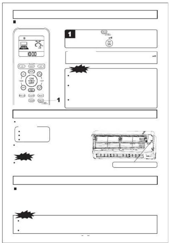
Emergency run operation procedure
Auto restart function after power interruption
Remote control handling procedure
When the operation fails with the remote control
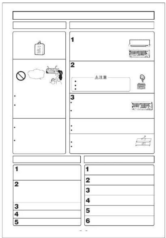
Operating hints
Maintenance
Installation, inspection and change of the filter screen
When to contact your distributor without delay
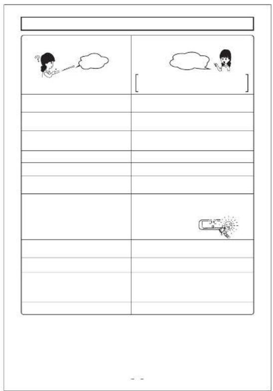
Troubleshooting
Self diagnosis function
Sheet, installation
-1
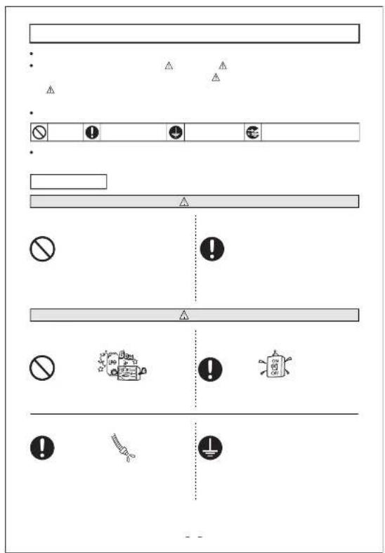
Safety precautions
- Before starting to use the system, please read these "Safety precautions" carefully to ensure proper operation of the system.
- The safety precautions are classified as “DANGER” and “CAUTION” Precautions as shown in the column “DANGER” indicate that improper handling could have dramatic consequences like death, serious injury, etc. Nevertheless, even precautions as shown in the column “CAUTION” might pose a serious problem, depending on the circumstances. Please observe these precautions with great care, since they are essential to your safety.
- Symbols which appear frequently in the text have the following meaning
Strictly prohibited ☐ Observe instructions with great care ☐ Provide positive anything ☐ Pull out of the power plug from the socket
- When you have read the instruction manual, please keep it near at hand for consultation. If someone else
takes over as operator, make certain that the manual is also passed on to the new operator.
INSTALLATION PRECAUTIONS
| DANGER | |
| The air conditioner is applied to domestic use. | The system must be installed by your dealer or a qualified professional. |
| It is used in the workshop of the factory or other server environment, the application function of the air conditioner will be reduced. | It is not advisable to install the system yourself, as finally handling may cause leakage of water, electric shock or fire. |
CAUTION
| Do not install near places where information gas may leak. | |
| Gas leaks may cause fire. | |
| Make sure that you drain the hose property, so that all the water has dropped out. | |
| Negligence may cause flooding in the room resulting in wet furniture. |
OPERATION PRECAUTIONS
| DO NOT EXPOSE YOURSELF TO THE COOING AIR FOR PROLONGED PIELDS. | DO NOT INSERT ANYING INTO THE AIR INLET. | THE REMOTE CONTROL SHALL BE PUT IN THE PLACE WITHOUT THE CHILD'S REACH |
| This could affect your physical condition and cause health problems. | This may cause injury, as the internal fan moves at high speed. | Since it may occur the accident such as the children swallow the battery wensily or other accidents. |
| Please never connect the power/te power socket in the middle and it is prohibited to use the prolonged win or use the same socket with other electric als apparatus. | Never start or stop the operation of the car conditioner by the method inserting or pulling out of the power line. | Before the power plug is inserted to the power socket, please make sure whether there is dust on it and insert it in the bottom without any gap. |
| The accident such as electric shock, heating and fire may occur. | The accident such as electric shock, heating and fire may occur. | If there are some dusts on the plug, please insert correctly, otherwise the accident such as electric shock or fire may occur. |
Safety precautions
| CAUTION | [7X00] | |
| Only use approved fuses. (Fuse specifica- tion 250V 3.15A) | Do not handle the sw hands. | with wet |
| (T7Y8) | ||
| (C4T4) | ||
| (T0W2) | ||
| Use of steel or copper wire instead of an app- roved fuse is strictly forbidden, as it may ca- use a breakdown or fire. | This may cause an elec | a.k. |
| (T4TK1) | ||
| (T2W0T) | ||
| (H4TDI) | ||
| Do not swing from the system. | Do not place a combust, paint spray near the b ecily at the system. | insecticide or nor aim it dir- |
| (02S04) | ||
| (E2X1) | ||
| (A4T9) | ||
| (A4M1) | ||
| (A3M2) | ||
| (A2X2) | ||
| If the system falls down, you may get injured. | This may result in a fire | |
| You should not expose any combustion appliance directly to the air stream of the air conditioner. | Do not wash the air cc | or with water. |
| (E2W48) | ||
| (E2W61) | ||
| (T5A4) | ||
| (E2X3) | ||
| (E2X1) | ||
| The appliance may then work inadequately. | This could cause an elec | ck. |
| The system should only be used for its original purpose and not for anything else like, torsance, presentation of food, plants or animals, precision devices or works of art. | Do not place anything like vasses, on top of t | ing water. |
| (E4X1) | ||
| (E4X2) | ||
| (T2B3) | ||
| (E0D3) | ||
| (E4Z7) | ||
| (L23A) | ||
| (H7T8) | ||
| The system is only intended for use in ordinary domestic rooms. Any other use of the sys- tem may damage the quality of food, etc. | Water entering the unit c ulation and therefore cau | mage the ins- electric shock. |
| (C6D2) | ||
| (C6D3) | ||
| (Y3B0) | ||
| Do not install the system at a place where the air stream of the blower is aimed dire- tly at plants or animals. | Do not sit on the ould anything on it. | nor put |
| (S6H0) | ||
| (Z2Y1) | ||
| (H2B1) | ||
| (H6C7) | ||
| This will damage their heal. | If the unit falls down or people could get hurt. | drop off it. |
| (T7Y4) | ||
| (CDC1) | ||
| (T6C1) | ||
| After a long period of usl unit s support structure fr | the to time. | exchanger |
| (S6H4) | ||
| (C5H7) | ||
| (A4X2) | ||
| (X4M4) | ||
| (H8T0) | ||
| (E7Z6) | ||
| If you don't repair any damal units may fall down and cause | way, the injury. | hing the fin |
| (A4X3) | ||
| (S8B0) | ||
| (N100) | ||
| (N8E) | ||
| (N9E) | ||


Safety precautions
 | |
| Never place the home appliance or domestic articles below the indoor and outdoor machines. | Frequent indoor air conditioner when the air conditioner air at the same time. |
| The underzation water falling from the air conditioner may probably dirt the articles and cause faults and elec- dust shock accident etc. | Hypoxia danger may be cause ventilation. |
| When loading and unloading the inspiration grid and filter network, it shall stand on the stepleadder family or other stable articles. | Stop operation and shut ok then cleaning the air condi l |
| Otherwise injury may be caused due to the falling of the article. | Never carry out cleaning wet machine is in high speed up e |
| Never place articles or accumulate leaves surround the outdoor machine of the air conditioner. | Please contact with your d teamal of the air conditioner |
| If there is article or leaves accumulating around the outer machine, some small animals may enter machine to contact with the electrical apparatus and cause short circuit, producing gas or flame. | The plastic parts of the machi water leakage will be caused or cleaning method to use. 1 parts of the electric apparatus line, it may destroy the air con gas, fire or other accident. |
| Off the air conditioner and cut off the power when you hear the thunder or dangerous lightning. | When the air condition has a long time, please pull to our the power socket to pull out. |
| Electric storm may damage the machine. | Otherwise if may accurate or the accident. |
| Please never damage or alter the power line. | |
| It may cause electric shock, heating or fire accident. The damage of the power line may be resulted in when placing berry wings or the power line, heating or prolonging the power line. | |
| PRECAUTIONS FOR TRANSFER OR REPAIRS | |
Choice of operations and features
Choice of operations
| COOL | DRY | |
| Cooling by extracting heat from the room. | Drying by extracting drying from the room. | |
 |  |  |
 |
Characteristics
| Amenity facility | TIMER procedure | HI POWER/JET mode |
| When using the timer to switch on, the system became operational shortly before the set time, depending on the room temperature so that the desired temperature is reached at the set time. | There are three timers, for SLEEP TIMER, ON TIMER and OFF TIMER. They can be set as desired. | Turning up the power operates the air conditioner in the power cooling and heating mode. |
| Wind flow adjustment function | Vertical wind-guiding blades Wind-guiding blades swing up and down continuously Horizontal wind-guiding blades Horizontal wind-guiding blades swing left and right continuously Memory wind-guiding blades (Vertical or horizontal wind-guiding blades stop the continuous cycle) Once the position of wind-guiding blades is set, the machine will memorize the position, and will run at the same position when starting running at the next time. | Comfortable air-supply modeShowering in the cold air (only for the cooling mode)You can feel the cold air everywhere in the room by adjusting the wind direction.Warming feet in the warm air (only for the heating mode)Your foot can also feel the warm air by adjusting the wind direction.Comfortable air-supply modeYou can regulate the indoor air and the air in the specific area by the regional setting function. |
5
Name of each part and its function
INDOOR UNIT

OUTDOOR UNIT

ACCESSORIES

5
Unit display section

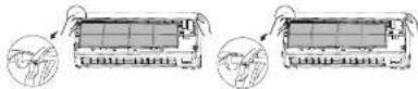
How to open the air inlet panel
Place figers at the recesses on both sides of the panel and pull up the panel to this side so that it will be opened by about 60 degrees.

How to close the air inlet panel
Push both sides evenly and press further lightly at the center.
Unit ON/OFF button
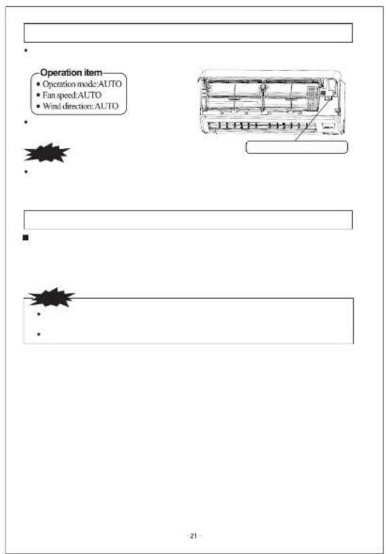
In emergencies, this button can be used for turning on/off the unit when remote control is not available.
Removal, installation of air inlet panel
When removing the air inlet panel for internal cleaning or others, open the panel by 65 degrees and then pull it to this side.
?
三菱図番 DWG. NO. SUFFIX PAGE MHI DWG. NO. RYD012A352 5/


| 三菱図番MHI DWG NO. | DWG.NO.RYD012A352 | SUFFIX | PAGE6/ |

| 三菱図番MHI DWG. NO. | DWG. NO.RYD012A352 | SUFFIX | PAGE7/ |

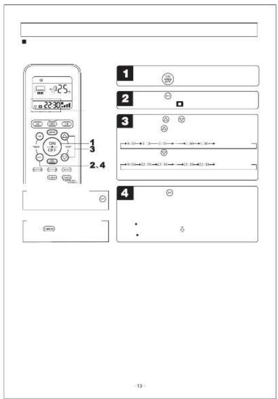
| 三菱図番MHI DWG. NO. | DWG. NO.RYD012A352 | SUFFIX | PAGE8/ |


| 三菱図番MHI DWG. NO. | DWG. NO.RYD012A352 | SUFFIX | PAGE9/ |

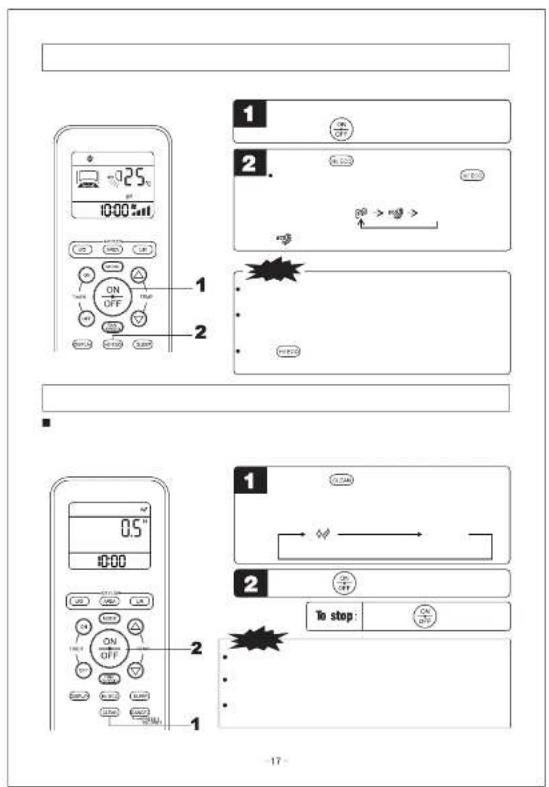
| 三菱冈番MHI DWG. NO. | DWG. NO.RYD012A352 | SUFFIX | PAGE10/ |
![graph TD A["Control Panel 1"] --> B["Control Button"] B --> C["Control knob"] C --> D["Control knob with ON/OFF status"] D --> E["Control knob with ON/OFF status"] E --> F["Control knob with ON/OFF status"] F --> G["Control knob with ON/OFF status"] G --> H["Control knob with ON/OFF status"] H --> I…](/content/2026/05/1043736/images/e4be6afba7e436a9f0a3333080b579f843f0ae999006a29c5c85b062eaeadb3f.jpg)
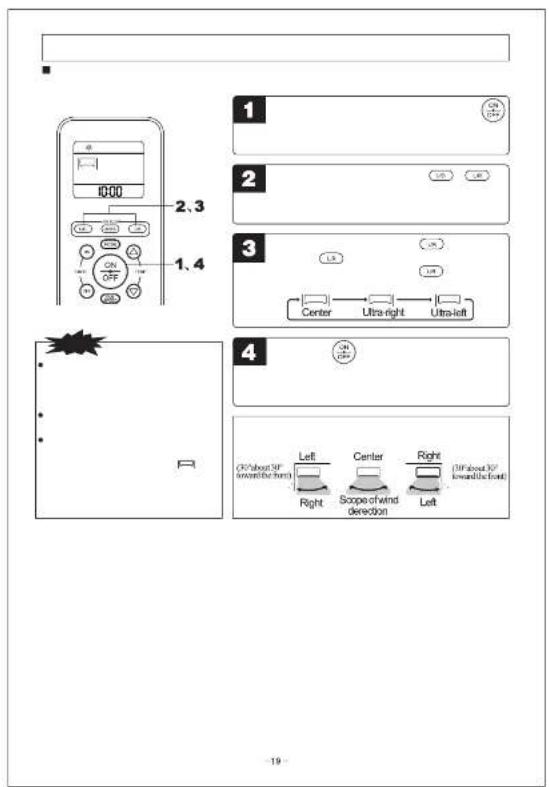
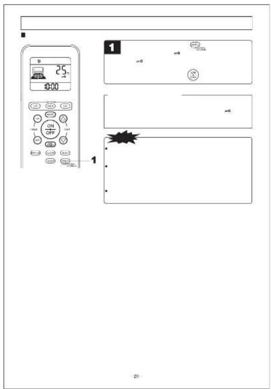


![(RUNlight on) Not operating? Please wait for three minutes. [ ] [ ] - - - - - - - - - - - - 27 -](/content/2026/05/1043736/images/17a21433e091f079c6e68f64a7bd65b48d856e553bf19da44d28505e6e9cbd65.jpg)
| 三菱図番MHL DWG. NO. | DWG. NO.RYD012A352 | SUFFIX | PAGE15/ |

| 三菱図番MHL DWG. NO. | DWG. NO.RYD012A352 | SUFFIX | PAGE16/ |
| Abnormal cases | Running indicator | Timing indicator | Temperature/depth | ||
| Indoor Unit | Sensor | Indoor heat exchange sensor is abnormal | On | ||
| Other | Indoor suction sensor is abnormal | On | - - | ||
| Indoor fan rotor is abnormal | On | ||||
| The communication of display panel is abnormal | - - | - - | |||
| Outdoor Unit | Sensor | Outdoor temperature sensor is abnormal | Flashing continuously | ||
| Outdoor heat exchange sensor (liquid tube) is abnormal | Flashing continuously | ||||
| Sensor on the top of compressor is abnormal | Flashing continuously | ||||
| Sensor of suction pipe is abnormal (only for continuous multi-compact) | Flashing continuously | ||||
| Others | Current protection power down | On | |||
| Failure of outdoor unit | On | ||||
| High-pressure protection control of refrigerator | On | Flashing continuity | |||
| Current security | On | ||||
| Compressor overheating protection | On | ||||
| Serial transmission error protection | On | ||||
| Outdoor fan rotor is abnormal | On | ||||
| Fault of power module | On | ||||
| Voltage of silicon controlled rectifier is abnormal | On | ||||
| Cooling cycle system protection | On | ||||
| Locked rotor |
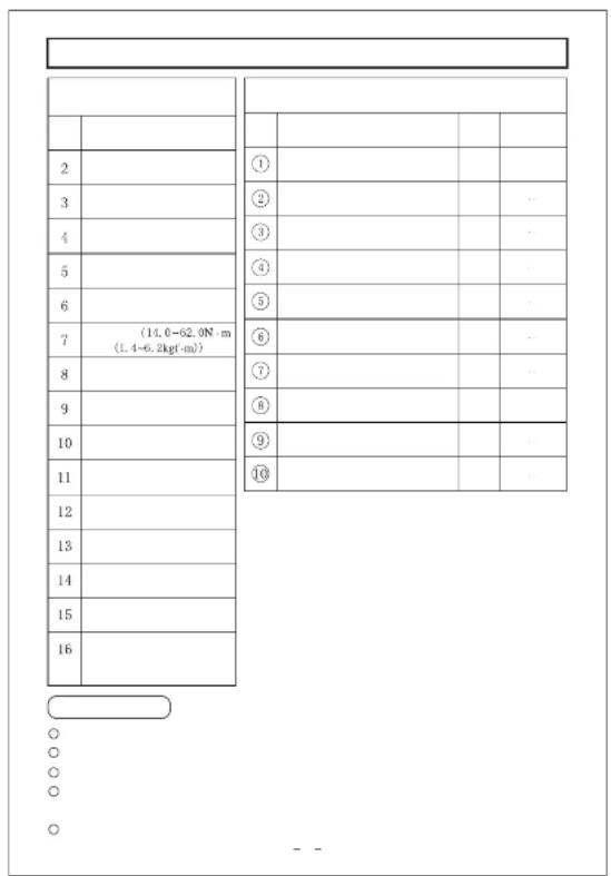
| Crosshead screwdriver | No. | Parts name | Qua-nity | Place for storage | |
| 2 | Knife | 1 | Indoor body | Indoor Packing | |
| 3 | Saw | 2 | Instillation board (attached behind the indoor body) | ||
| 4 | Tip | 3 | Self-tipping screw (used for instu-ation board) | ||
| 5 | Hammer | 1 | Battery (R03 1.5V) | ||
| 6 | Wrench | 5 | Instruction for application and inst-lation | ||
| 7 | Torque wrench 14.0–62.0X.m (1.4–6.2kgf.m) | 6 | Remote control | ||
| 8 | Hollow drill (85mm diameter) | 7 | Fiber assy | ||
| 9 | Hexagon wrench (hexagon)[4mm] | 8 | Outdoor body | Outdoor Packing | |
| 10 | Vacuum pump | 9 | |||
| 11 | Adaptor of the vacuum pump (anti-backward flow type) (professional for R410A) | 10 | |||
| 12 | Pressure gauge group (professional R410A) | ||||
| 13 | Charging hose (profes-ional for R410A) | ||||
| 14 | Flaring tools (professional for R410A) | ||||
| 15 | Leak detector (professional for R410A) | ||||
| 16 | Adjustment regulation of the horn port (used when the c-common flaring tools are adopted for tube expanding) | ||||
Points for attention for installation
| ○ | ○ | ○○○ |
| ○ | ○ | ○ |
| ○ | ○ | ○ |
32
| Safety precautions | |
| CAUTION | WARNING |
| WARNING | |
| CAUTION | |
| △ WARNING | |
| ● | |
| ● | |
| ● | |
| ● | |
| ● | |
| ● | |
| ● | |
| ● | |
| ● | |
| ● | |
| ● | |
| ● | |
| ● | |
| ● | |
| ● | |
| ● | |
| ● | |
| ● | |
| ● | |
| ● | |
| ● | ! |
| ● | |
| ● | |
| ● | |
| ● | |
| ● | |
| ● | |
| ● | |
| ● | |
| ● | |
| ● | |
| ● | |
| ● | |
| ● | |
| ● | |
| ● | |
| ● | |
| ● | |
| ● | |
| ● | |
| ● | |
-33
| 三菱図番MHL DWG. NO. | DWG. NO.RYD012A352 | SUFFIX | PAGE18/ |


How to unload and install the front panel
○Unloading
① Unload the inspiration grid ② Unload 2 screws fixing the front panel.
③ Unload 3 lock bars in the lower part of the front panel and then unload the front panel from the equipment.
○ Installation
① Unload the air filter screen. ② Cover the equipment by front panel cover.
③ Fasten 2 screws and fix the front panel. ④ Install the air filter screen. ⑤ Install the inspiration grid.

Installation of the indoor unit
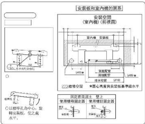
Installation of installation board
Fix the installation board

O
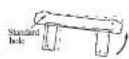
2.
Set the relationship between the
board and indoor machine
Installation space
(Indoor machine) (Front view)

| Fix on the concrete wall | |
| Using nut fixer Using screw fixer | Using nut fixer Using screw fixer |
36
Installation of the indoor equipment
Fixation of the drilling and sleeve (optional parts)
Ø165 core drill is used for drilling
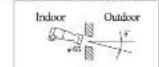
☐ The core drill is used for drilling
Install the sleeve

○ Insert the sleeve
Schematic diagram of the status after installation

Adjust the length of the sleeve
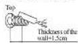
○ If the back piping is pulled out, cut the lower part and right side of the axis circulation.
Sleeve Inclined board Sealed ring

CAUTION
Drill a hole with 5° inclined angle for indoor to outdoor
Installation preparation of the indoor machine
Installation preparation of the wire connection
① Open the inspiration grid.
② Unload the cover.
② Open the wire clamp.
4. Connect the wire to the connection board firmly.
1) Connect the wire to the connection board firmly. If the wire has not fixed well, it may cause power connection and danger, since the connection board may produce heat and cause fire.
2) Never get confused about the quantity of the terminals of the indoor and outdoor connections.
⑤ The wire clamp is used to fix and connect the wire.
⑥ The wire clamp is used to connect the wire.
⑦ Close the inspiration grid.
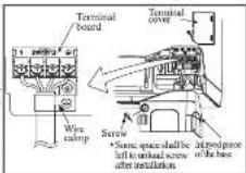
CAUTION
If the routing connection encounters some faults, the indoor machine will stop operation, the operation lamp will be on and the timer lamp will flash.
37
Install the piping stent
Shaping the pipe

○Hold the root of the pi-
ping and carry out she- ping to the prolonged part after pulling out of the pipe.

○ Tape only the portion that runs through the wall. Always tape the crossover wires with the pipe.
C The routing must be winded together with the external insulation belt.
○ Start from the lower part of the piping when bandaging the 1-nsulation belt to avoid the invasion of the rainfall.
Fixation of the indoor machine
Indoor machine

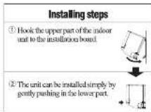
- How to remove the indoor unit from the installation board
① Push up at the marked portion of the indoor unit base lower latch, and slightly pull it toward you. (both right and left hand sides) (The indoor unit base lower latch can be removed from the installation board)
② Push up the indoor unit upward. So the indoor unit will be removed from the installation board.
- Points for attention when connecting to the left and the center [Top view]

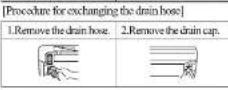
○1. Loosen and remove the spring-type clamp. ○2. Remove with your hand or a pair of pliers.
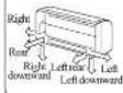
Piping is possible in the rear, left, left rear, left downward, right or downward direction.
-Loosen the spring-type clamp and securely insert the drain hose. Caution: Becareful because if the cap is not inserted properly, water leak may occur;

Drainage pipeline
○ Install the drainage hose in the lower angle. ○ The lower drainage nozzle shall be avoided

Higher than the

The tip of the drainage
house is within the winter
Pour water to the drainage disk under the heat exchanger to guarantee that the water has discharged outside the room.
When the prolonged drainage hose is within the room, the shield pipe (user installation) must be used to ensure the thermal insulation.
CAUTION After undergoing all the procedures, start to inspect whether the drainage is proper, otherwise, water leakage may be incurred

Less than 5cm from the ground
The tip of
house is a watermark
Shield pipe
1
1/2x2-1/2y2=0
Drainage box Being naked with Prologal drin
Installation of the outdoor machine
Please make sure the place where the outdoor machine is installed is fixed first and then installation can be carried out.
When installed in a place with a relatively high position or easily suffer from invasion of the strong wind, please adopt the anchor bolt, wire and others to fix the machine firmly.
○ Connection can be carried out after making sure that the number of the connection terminal complies with that of the indoor machine.
- Please adopt the foot pin near ⏻ mark for connection.
- When the temperature is lowered below 0 °C, never install the drainage elbow.
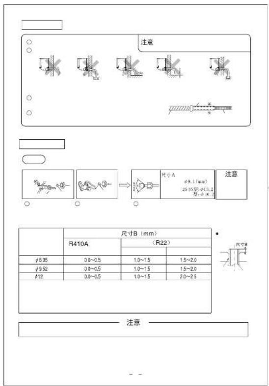
Piping connection
Keep the operation of the pipes covered with tapes etc. to prevent dust, sand etc. from entering them.

○ Remove the flamed nuts (on both liquid and gas sides)

Remove the flared nuts (on both liquid and gas sides)

Install the removed flared mts to the pipes to be connected, then flare the pipes.

Ethylene hose It is the ethylene hose sold in the market) It is only applied the hot pump typ

| MODEL | Size B(mm) | ||
| R410A close typeflaming tools | Common (R22) flaming tools | ||
| Close type | Airfoil nut type | ||
| ≠ 8.35 | 0.0~0.5 | 1.0~1.5 | 1.5~2.0 |
| ≠ 9.52 | 0.0~0.5 | 1.0~1.5 | 1.5~2.0 |
| ≠ 12.7 | 0.0~0.5 | 1.0~1.5 | 2.0~2.5 |

CAUTION
Do not use the excessively large torque on the flaring nut, otherwise the flaring nut may break and the refrigerant may leak.
Connection
Indoor

Outdoor
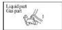
○ The liquid part and gas part connect at the same time.
○ The fastening torque is as follows at this time:
Liquid part(Φ6.35):14.0\~18.0N·m(1.43\~1.84kgf·m)
Gas part (Φ9.52):34.0-42.0N·m(3.47-4.29kgf·m)
(Φ12.7):49.0-61.0N·m(5.00-6.22g·m)
○ The liquid part and gas part connect at the same time.
○ All the torques are the same with
the indoor
Air purge
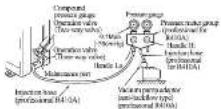
-
•
40
| piping | |||
| type | type | type | |
| Length of largest piping | 25 - type | ||
| within15n | |||
| Difference of the vertical height | within 5n | ||
| Adding refrigerant | no need | ||
Installation of the connection part
Post-treatment and fixation
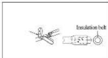

Earthing work
。
Moving or unloading the machine
0
中

41
三蕊刘秀
MH DWG NO
DWG. NO
RYD012A352
SUFFIX PAGE
/



- CONTENTS
- SAFETY PRECAUTIONS
- CHOICE OF OPERATIONS AND FEATURES
- CHOICE OF OPERATIONS
- CHARACTERISTICS
- HOW TO UNLOAD AND INSTALL THE FRONT PANEL
- INSTALLATION OF THE INDOOR UNIT
- SET THE RELATIONSHIP BETWEEN THE
- INSTALLATION OF THE INDOOR EQUIPMENT
- FIXATION OF THE DRILLING AND SLEEVE (OPTIONAL PARTS)
- INSTALLATION PREPARATION OF THE INDOOR MACHINE
- INSTALLATION PREPARATION OF THE WIRE CONNECTION
- INSTALL THE PIPING STENT
- SHAPING THE PIPE
- FIXATION OF THE INDOOR MACHINE
- INDOOR MACHINE
- DRAINAGE PIPELINE
- INSTALLATION OF THE OUTDOOR MACHINE
- PIPING CONNECTION
- CAUTION
- CONNECTION
- INDOOR
- OUTDOOR
- AIR PURGE
- INSTALLATION OF THE CONNECTION PART
- POST-TREATMENT AND FIXATION
- EARTHING WORK
- MOVING OR UNLOADING THE MACHINE
Brand : MITSUBISHI
Model : SRK50RE1
Category : Measurement