
iSPD PRO - Audio Equipment PEAVEY - Free user manual and instructions
Find the device manual for free iSPD PRO PEAVEY in PDF.

| Product Type | Intelligent Sequential Power Distribution System |
| Brand | Peavey |
| Model | iSPD PRO |
| Number of Outlets | 8 |
| Maximum Load per Outlet | 15 A |
| Input Voltage | 100-120 VAC, 50/60 Hz |
| Default IP Address | 192.168.1.81 |
| Communication Port | UDP port 1202 |
| RS485 Baud Rate | 115200 bps |
| Control Interfaces | Front panel key switch, remote switch (Euro connector), Ethernet (RJ45), RS485 (Euro connector) |
| Power Sequencing | Programmable delay per outlet (default 1 second), power on 1→8, off 8→1 |
| Linking Capability | Up to 8 units via RS485 twisted pair |
| Monitoring | Via Ethernet and settings & management software |
| Compliance | FCC Part 15, ICES, Class B digital device |
| Display | Line voltage display and 8 channel status LEDs |
| Safety Warnings | Caution: may cause interference; follow installation instructions; comply with FCC radiation exposure limits |
| Maintenance | Keep dry; clean with dry cloth; unplug before cleaning; do not use liquids |
| Spare Parts and Repairability | No user-serviceable parts; contact Peavey for servicing; warranty available online |
| Warranty | Available online at www.peavey.com/warranty (for US customers) |
| Included Software | iSPD Settings and Management software for configuration and monitoring |
| Dimensions | Not specified (standard 1U rackmount likely) |
| Weight | Not specified |
Frequently Asked Questions - iSPD PRO PEAVEY
User questions about iSPD PRO PEAVEY
0 question about this device. Answer the ones you know or ask your own.
Ask a new question about this device
Download the instructions for your Audio Equipment in PDF format for free! Find your manual iSPD PRO - PEAVEY and take your electronic device back in hand. On this page are published all the documents necessary for the use of your device. iSPD PRO by PEAVEY.
USER MANUAL iSPD PRO PEAVEY
natural_image
Abstract geometric logo design with stylized arrow-like shapes (no text or symbols)iSPD PRO
Intelligent Sequential Power Distribution System
Operating
Manual


FCC/ICES Compliancy Statement
This device complies with Part 15 of the FCC rules and Industry Canada license-exempt RSS Standard(s). Operation is subject to the following two conditions: (1) this device may not cause harmful interference, and (2) this device must accept any interference received, that may cause undesired operation.
Warning: Changes or modifications to the equipment not approved by Peavey Electronics Corp. can void the user's authority to use the equipment.
Note – This equipment has been tested and found to comply with the limits for a Class B digital device, pursuant to Part 15 of the FCC Rules. These limits are designed to provide reasonable protection against harmful interference in a residential installation. This equipment generates, uses, and can radiate radio frequency energy and, if not installed and used in accordance with the instructions, may cause harmful interference to radio communications. However, there is no guarantee that interference will not occur in a particular installation. If this equipment does cause harmful interference to radio or television reception, which can be determined by turning the equipment off and on, the user is encouraged to try and correct the interference by one or more of the following measures.
• Reorient or relocate the receiving antenna.
- Increase the separation between the equipment and receiver.
- Connect the equipment into an outlet on a circuit different from that to which the receiver is connected.
- Consult the dealer or an experienced radio/TV technician for help.
Caution
The equipment complies with FCC radiation exposure limits set forth for an uncontrolled environment.

Peavey Electronics Corporation • 5022 Hartley Peavey Drive • Meridian, MS • 39305
Intelligent Sequential Power Distribution
The iSPD Pro is a programmable power sequencer with many applications in the audio/Video industry. Each of its 8 power outlets is individually controlled and its delay time can be individually set. Any of the 8 outputs can also be configured for constant on as well. When your requirements call for more than one unit, up to 8 iSPD Pro sequencers can be inter-connected via an RS 485 interface requiring only with a simple twisted pair. The units can be configured and monitored over Ethernet using the management software provided.
There are several reasons to use a power sequencer to turn on system equipment. When powering on sound system equipment, it is always a good idea to power on low level equipment like mixers and signal processor first allowing them to stabilize before energizing the power amplifiers. This helps prevent unintended pops and noises from being amplified and sent to the loud speakers. Most electronic equipment requires a surge of power from the power line when it is first turned on. This is a even bigger issue for high power devices like power amplifiers. By sequencing the turn-on of equipment, the instantaneous power demand can be greatly reduced.
Features
- 8 output channels with individually adjustable delay time.
- Front panel or remote power sequence control.
• Additional units may be linked for expanded capacity. - Control Graphical interface program for custom configuration and monitoring over Ethernet.
Front Panel
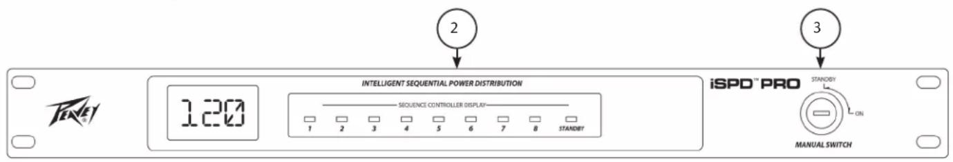
(1) Line Voltage display.
The current line voltage is displayed. Make sure that the line voltage is correct before activating the switch to turn on the connected equipment.
(2) Sequence Controller Display
The status of each of the 8 outputs is shown in this display. The LEDs illuminate when their corresponding outlet circuit is energized. The Status LED is illuminated when the iSPD is connected to a power source.
(3) Key Switch
When the front panel key switch is turned to the on position, the power up sequence is initiated energizing outputs 1 to 8 in order. Returning the switch to the standby position reverses the sequence, turning off the output circuits from 8 to 1. This same control function can be initiated by using a customer supplied switch connected to terminals on the rear of the unit. For more information on its operation, see the section describing remote switch control.
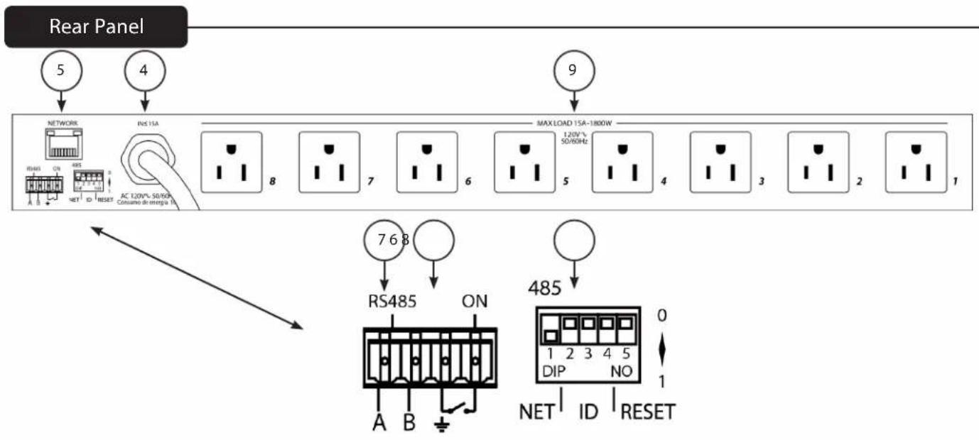
(4) Power Cord
Connect the power cord to a 100 V to 120 VAC 50/60 Hz power source.
(5) Network
Ethernet connection for remote configuration and control. Delay times before turn on of each circuit can be adjusted, circuits can be programmed for constant on and individual circuits can be controlled using this interface and the iSPD control program.
(6) Remote Switch connections
Two terminals of the four position Euro connector are used for connection of a remote switch that can initiate the power on and off sequence. Closing a switch connected to those pins initiates the power on sequence. Opening the switch initiates the power off sequence.
However, there is interaction between the front panel key switch and the remote switch. If the unit is off, either switch will turn the unit on. If both the Key switch and remote switch are on, turning either switch off will power the unit off. In this case one of the switches will still be on the on position. To turn the unit on from that switch, it must first be turned off then back on. In most cases it is best to use either the key switch or remote switch only.
(7) Euro Connector RS 485 "A B" (Linking multiple iSPD units)
The RS 485 "A and B" connections are used to network multiple iSPD units. A simple twisted pair connection is all that is required to interconnect units. RS 485 interface is a multi-drop serial bus with all units wired together A to A and B to B. For long distance connections a controlled impedance cable such as one pair of a CAT 5E or DMX cable works well.
(8) Network Configuration and Reset Switches
Refer to Appendix A for details about setting these switches.
(9) Power Outlets
The power outlets are numbered 1 to 8. The iSPD applies power to these outlets in a 1 to 8 sequence. When power is turned off, the sequence is reversed with outlet 8 turning off first and outlet 1 last. Keep this sequence in mind when connecting equipment to these outlets.
Operation
Setup and Operation.
Connect the power inlet of the iSPD to an appropriate power source. The "STANDBY" LED will light indicating the inlet power is present. Connect the load equipment to the outlet receptacles. Pay attention to outlet power on sequence when connecting loads. Audio devices like mixers and signal processors with low level signals that are early in the signal chain should power on first. High signal level devices like power amplifiers that are at the end of the signal chain should power on last.
Turning the key from the "STANDBY" to "ON" position initiates the power on sequence, turning on outputs 1 to 8 in order. The Front panel LEDs, 1 to 8 will light as those circuits become active. Alternately, an external switch can be connected to the remote terminals on the rear that initiates the sequence. If using an external (remote switch), leave the front panel key switch in the standby position.
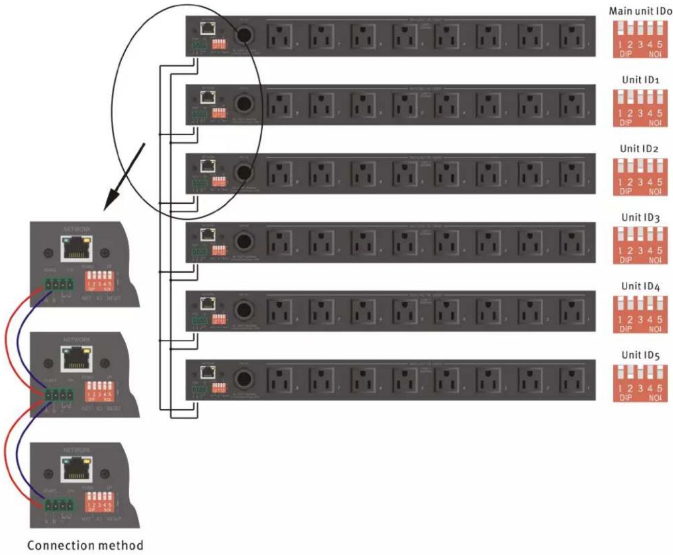
Connecting additional units
iSPD units can be linked when either more circuits are needed or when the circuits to be controlled are in different locations. By linking the units, one switch can sequentially control the entire system. The "power on" sequence starts with the master unit (ID# 0) and continues in order of ID. Do not skip ID numbers when connecting additional units.
To link iSPD units:
- Connect the RS 485 port of all of the linked units together on a common bus. Wire A to A and B to B. It would be advisable if there is a long distance between units to use 110 Ohm cable such as Cat 5e or DMX 512.
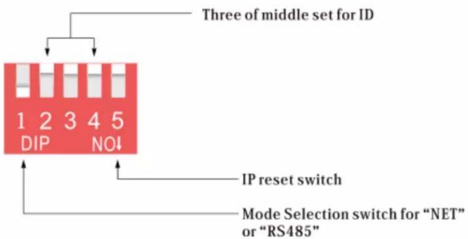
- Set the net switch on the master unit to ON (down). This switch and the channel ID switches are located on the rear of the unit. (See connection method diagram and appendix for switch details)
- Set the ID# on the master unit to "0". Set the ID#s of the additional units in the sequence you wish them to turn on. Do not skip ID numbers.
- Use the key switch or remote switch connection on the master unit (ID#0) to control the system.
- If you want to monitor the system, connect the Ethernet port of each unit to a router or switch along with the computer running the Settings and management software. You will need to change the IP address of all but one of the iSPD units so that they do not have the same address. Make sure that they are in the same subnet. For example: 192.168.1.100, 192.168.1.101 ..... etc.
flowchart
graph TD
    A["Main unit IDo"] --> B["Switch 1"]
    A --> C["Switch 2"]
    A --> D["Switch 3"]
    A --> E["Switch 4"]
    A --> F["Switch 5"]
    B --> G["Network 1"]
    C --> H["Network 2"]
    D --> I["Network 3"]
    E --> J["Network 4"]
    F --> K["Network 5"]
    G --> L["Connection method"]
    H --> L
    I --> L
    J --> L
    K --> L
PC "Settings and Management" software
Although the iSPD power sequencer is completely usable out of the box, the iSPD settings and management software allows the user to monitor the state of the each iSPD output, control the turn-on delays and set outputs to constant on. IPv4 address can also be changed using this program.
The simplest method for connecting the iSPD to your computer is to use a small router with a network address range of 192.168.1.xxx. Your computer should receive an address in the correct range and it will automatically connect once the program is launched. However, you can directly connect the PC to the iSPD with an Ethernet cable, but you may need to set the network interface on your PC to connect using a static IPv4 address. We recommend IPv4 address of "192.168.1.250" with a subnet mask of "255.255.255.0" if necessary.
Start the Program
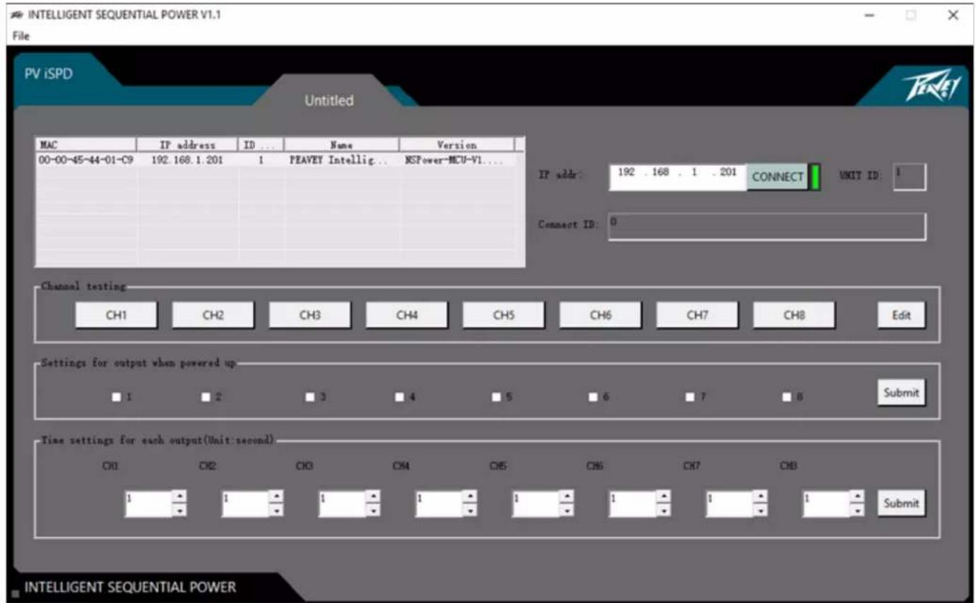
The program will search the network for connected Devices and list them in the upper left area of the screen. Click to select the device you wish to configure and monitor then click the connect button. The green indicator next to the connect button indicates you are connected. If monitoring multiple iSPDs, after you have connected to each of the units, simply click on the device you wish to monitor in the list.
Name Output Channels
Names can be applied to each of the 8 channels identifying the device it is controlling.
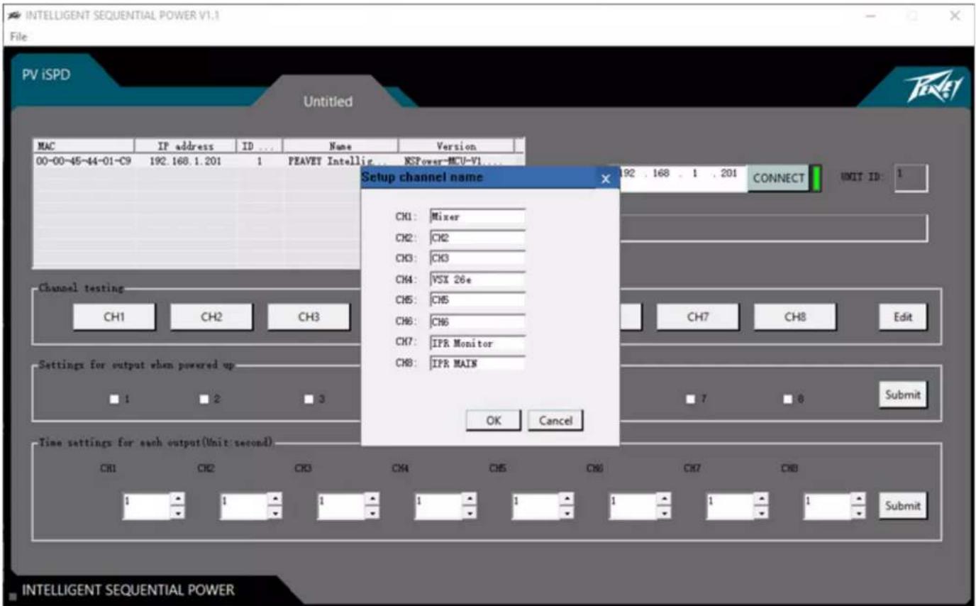
Click "Edit" to the right of the channel testing boxes to bring up the Channel name screen. Click OK when complete.
Test Outputs
Individual outputs can be tested by clicking the channel number or device name in the Channel test area. This will turn the selected circuit On or Off. Green indicates the circuit is on and white off.
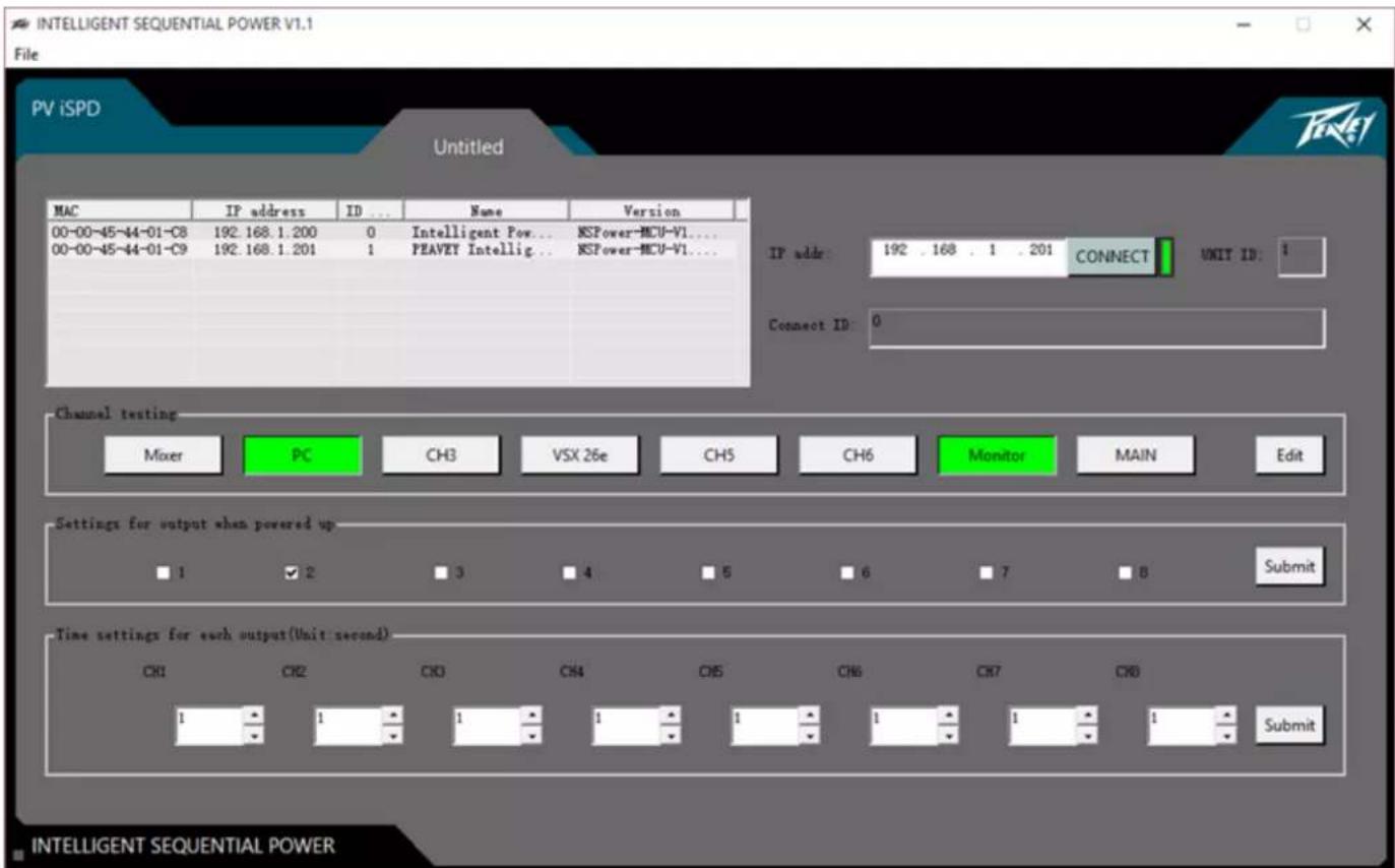
Always On
There can be situations when you want outputs to be always on. In the "Settings for output when powered up", check the boxes you wish to remain ON and click "Submit". These channels will then turn on and will come on whenever power is applied to the iSPD Pro.
The box labeled "Time settings for each output" is used to set the delay in seconds for each output. The delay time is the time from when the previous channel is activated. So with the default settings of 1 second each, there will be a 1 second delay between each output activation and it will take 8 seconds to activate all circuits. There may be cases, especially in larger systems that you may wish to set a delay to 0. Use the up/down arrows to change the delay setting then click submit to send the changes to the unit.
Setting Device Name and IP Address
Double click on the iSPD in the list to bring up the dialog box for changing the IP address and unit name.
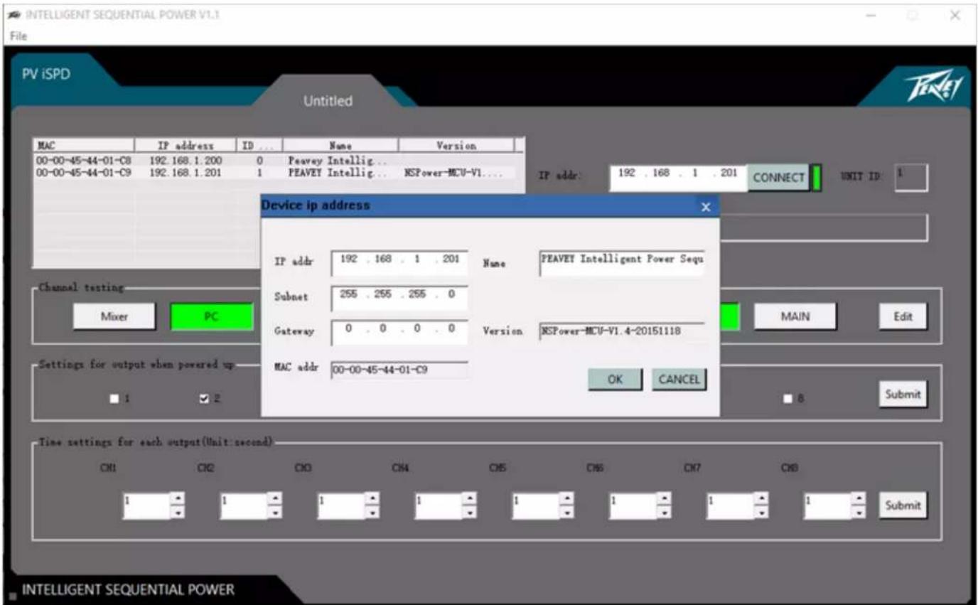
When monitoring multiple units, the IP address, which is static, will need to be changed. It is also beneficial to change the name of each unit to aid in identification when monitoring. Click OK when complete.
Resetting the IP Address to Factory Settings
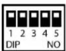
If the IP address has been changed, and you can no longer connect, it can be reset back to the factory default using the reset switch. To reset, move the right hand switch on the rear of the unit (6) to the down position then back to the up position. The IP address will be reset to the factory default. 192.168.1.81
Reset: Switch 1, Switch 2, Switch 3, Switch 4, Switch 5: (up, up, up, up, down then up)
Specifications
Maximum load current on each channel 15A
Input voltage 100-120 VAC 50/60 Hz
Default IP address 192.168.1.81
UDP communication Port: 1202
RS 485 Baud rate: 115200
* specifications and features subject to change without notice.
Appendix A: Network and ID# Switches:
The following messages can be sent to the iSPD using UDP messaging on port: 1202
Sequence all outputs on:
Text: (ALL_OPEN
Sequence all Outputs Off:
Text: (ALL_CLOSE
Turn ON one channel:
CH_ON ID=xx[y]
For example ID#=00 and channel #1
Hex: 43 48 5F 4F 4E 20 5B 49 44 3D 30 30 5D 5B 31 5D 0D 0A
Turn OFF one channel:
CH_OFF ID=xx[y]
For example ID#=00 and channel #1
Hex: 43 48 5F 4F 46 46 20 5B 49 44 3D 30 30 5D 5B 31 5D 0D 0A
Get channel Status:
GET_STATUS ID=xx
The unit returns:
Where the eight s's represent the eight channels. s=0 for OFF and s=1 for ON
Note: in all of the above examples

www.peavey.com
Warranty registration and information for U.S. customers available online at
www.peavey.com/warranty
or use the QR tag below

Features and specifications subject to change without notice.
Peavey Electronics Corporation
5022 Hartley Peavey Drive
Meridian, MS 39305
(601) 483-5365
FAX (601) 486-1278

Logo referenced in Directive 2002/96/EC Annex IV (OJL)37/38,13.02.03 and defined in EN 504-19:2005
The bar is the symbol for marking of new waste and is applied only to equipment manufactured after
13 August 2005


- iSPD PRO
- Intelligent Sequential Power Distribution System
- Caution
- Features
- Line Voltage display.
- Sequence Controller Display
- Key Switch
- Power Cord
- Network
- Remote Switch connections
- Euro Connector RS 485 "A B" (Linking multiple iSPD units)
- Network Configuration and Reset Switches
- Power Outlets
- Operation
- Setup and Operation.
- Connecting additional units
- To link iSPD units:
- PC "Settings and Management" software
- Start the Program
- Name Output Channels
- Test Outputs
- Always On
- Setting Device Name and IP Address
- Resetting the IP Address to Factory Settings
- Specifications
- Appendix A: Network and ID# Switches:
Brand : PEAVEY
Model : iSPD PRO
Category : Audio Equipment