P81 - Gas detector Fantini Cosmi - Free user manual and instructions
Find the device manual for free P81 Fantini Cosmi in PDF.

| Product Type | Gas Detector |
| Brand | Fantini Cosmi |
| Model | P81 |
| Category | Gas Detector |
| Detected Gases | Natural gas (methane) and LPG (propane/butane) |
| Power Supply | 230 V AC (mains powered) |
| Backup Battery | 9 V alkaline battery (optional) |
| Alarm Type | Audible (85 dB at 1 m) and visual (red LED) |
| Alarm Threshold | 10% LEL for methane, 20% LEL for LPG |
| Dimensions (H x W x D) | 120 x 80 x 30 mm |
| Weight | 200 g |
| Operating Temperature | -10°C to +50°C |
| Operating Humidity | 0% to 95% RH (non-condensing) |
| Installation | Wall-mounted, near potential gas sources (boiler, cooker, etc.) |
| Test Function | Press "Test" button to simulate alarm |
| LED Indicators | Green (power), Red (alarm), Yellow (fault) |
| Maintenance | Vacuum clean grille every 3 months; test weekly |
| Compliance | EN 50194 (Europe) |
| Lifespan | 5 years from power-on date |
| Warranty | 2 years (manufacturer) |
Frequently Asked Questions - P81 Fantini Cosmi
User questions about P81 Fantini Cosmi
0 question about this device. Answer the ones you know or ask your own.
Ask a new question about this device
Download the instructions for your Gas detector in PDF format for free! Find your manual P81 - Fantini Cosmi and take your electronic device back in hand. On this page are published all the documents necessary for the use of your device. P81 by Fantini Cosmi.
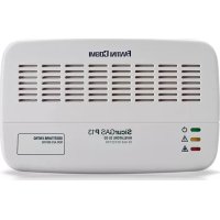
USER MANUAL P81 Fantini Cosmi
Electronic control unit for gas leak detection with 1 detection zone
Electronic control unit for gas leak detection in industrial environment, suitable for controlling and signaling dangerous gas concentration in the air, specifically for detecting methane gas, LPG and carbon monoxide.

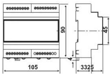
Dimensions (mm)
Power supply
Contacts rating
Connected sensors
Operating ambient temperature
Protection degree
P81 12 Vac or 12/14 Vdc 5A - 250V 1 - 10 ÷ 50 °C IP40
ELECTRICAL CHARACTERISTICS
Power supply: 12 Vac/dc ± 10%.
Absorption:
■ approximately 160mA (320mA) with a single probe;
■ 460mA (620mA) with faulty probe and output.
Connection with 2 terminals of 2.5 mm ^4
Protection: input - fuse power supply 1A 5x20mm.
1 input for sensors S81, S82, S83, or probes ATEX S84, S85, S86 (different gas types).
Connection to the probe with 3 terminals of 2.5 mm²: C (-12...24V); S (+4...20mA); A (+12...24V).
Maximum connection length 50 m.
Section of 3 conductors: 1.5 mm².
Outputs connections:
■ n.3 terminals of 2.5 mm² for relay C-NC-NO;
n.2 terminals of 2.5 mm ^4 for open collector.
Complies with the standards EN 61779-1-4; CEI 216-5/1 Directives/Norms EMC EMC 89/336/CEE, Norm EN 50270
CE EAC
INSTALLATION
Rear panel mounting on Omega DIN EN 50022 rail.
It can be installed on the bottom panel or DIN modular panels.
To ensure the proper protection degree of the device is necessary to install the unit in an electric box created according to current regulations for the workplace and within which can also be housed the power supply system.
OPERATION
P81 control unit allows you to connect a probe model S81-82-83 or ATEX S84, S85, S86 probes for the construction of gas detection systems in environments such as boiler rooms, garages, warehouses, workshops, etc., with the possibility to control a solenoid valve or an auxiliary device (siren, flashing light, extractor, etc..) through inside alarm relay.
The control unit must be powered at 12 Vac/dc.
The functioning logic, selected by means of jumper E1, can be either positive or negative. The device reports its operation status through the LED.
According to the selected logic through the jumper E1, in normal situation (no alarm), the led, the failure signaling output and the relay, are:
■ positive logic: led switched on, relay energized, failure signaling output = ON;
- negative logic: led switched off, relay not energized, failure signaling output = OFF.
In case was selected the negative operation logic, the alarm relay can be controlled continuously or pulsed, depending on Jumper E2 position:
Position A positive logic
Position B negative logic
Position A alarm relay continuous control
Position B alarm relay pulse control
A
B
E
A
B
[Unrecognizable Symbol]
A
E

E
A
B

E2
A
B

E2
A
B

E2
Once it was received the proper power supply, the control unit performs in sequence the following steps:
TESTING THE LED AND THE BUZZER (APPROXIMATELY 5 SECONDS)
Whatever the selected logic, the LEDs are starting to light in sequence and the buzzer emits a short beep.
PROBE PREHEATING (APPROXIMATELY 1 MINUTE)
During this phase, which allows the probe to reach the correct operation temperature, the detection system is not functioning.
FUNCTIONAL TEST (ABOUT 3 MINUTES)
Once the probe preheating phase has finished, the device enters under functional test phase. During this phase all internal timings are resetted in order to facilitate probe operation verification (alarm simulation).
During normal operation of the control unit is activated the gas alarm monitoring, as well the self-diagnoses for installation failures (probes) and of the system (control units). In this phase and in the absence of the alarm and the anomaly, the control unit is presented as shown in the table on the right.
INTERFACE POSITIVE LOGIC NEGATIVE LOGIC
| Power supply led Green Switched ON Switched ON | ||
| Failure led Yellow Switched ON Switched OFF | ||
| Gas alarm led Red Switched ON Switched OFF | ||
| Alarm buzzer No sound | No sound | |
| Alarm relay | Energized | Not energized |
| Failure output | ON | OFF |
In the presence of dangerous gas concentrations, the unit enters in gas alarm phase and performs the following operations, indicated in the table on the right.
| INTERFACE POSITIVE | NEGATIVE LOGIC | |
| LOGIC | ||
| Gas alarm led Red Switched OFF Switched ON | ||
| Alarm buzzer Continuous sound Continuous sound | ||
| Alarm relay Not energized | Energized (continuously | or pulsed according to e2) |
| failure relay | ON | OFF |
Once the gas alarm condition was surmounted is necessary to bring the control unit in normal operation condition.
For this purpose must be pressed the "RESET/TEST" button, situated on the front.
In the presence of a failure (probes and/or control units) the control unit will be represented like in the table on the right.
INTERFACE POSITIVE LOGIC NEGATIVE LOGIC
| Failure led Yellow Switched off Switched on | ||
| Alarm buzzer Intermittent | Sound | Intermittent Sound |
| Failure output OFF ON | ||
Once the possible failure was eliminated, is
necessary to bring the control unit in normal operation condition. For this purpose must be pressed the "RESET/TEST" button, situated on the device front.
It is recommended to repeat the procedure of operation verification at least once a year, or after a prolonged shutdown period, and anytime when is replaced the probe.
The average life time of S81-S82-S83 probes and S84-S85-S86 is 5 years from date of installation. It is mandatory to replace them before the expiry of 5 years of use.
The average life time of the probes is calculated taking into consideration a typical use in a normally free of contaminants (gases, thinners, etc.) environment. A more frequent presence and in higher concentrations of these substances can accelerate the normal oxidation process of the sensing element, resulting with its life time decrease.
TECHNICAL FEATURES
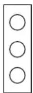
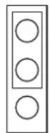
Light signals:
■ 1red LED, power supply ON;
■ 1 yellow LED, failure;
■ 1 red LED, gas alarm.
Acoustic signals:
■ 1 buzzer with sound intensity >60db at 1m.
■ 1 button to reset the alarms and for testing the probe.
Self-extinguishing plastic housing.
Dimensions: 105 x 90 x 58 mm - 6 modules complies with DIN 43880 standard.
Unit weight: 0,185 kg.
Rear panel mounting on Omega DIN EN 50022 rail.
Protection: IP20; IP40 when is properly installed in an electrical box.
Environment temperature: 0 ÷ 50^ .
Environment humidity ±90% U.R. without condensation.
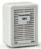
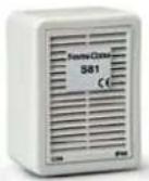
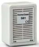
S81
Sensor for methane gas detection.
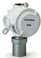
S84
Probe for methane gas detection, certified with ATEX II 2G Ex d IIC T6.
S82
Sensor for LPG gas detection.

S85
Probe for LPG gas detection, certified with ATEX II 2G Ex d IIC T6.
S83
Sensor for carbon monoxide detection.

S86
Probe for carbon monoxide detection, certified with ATEX II 2G Ex d IIC T6.
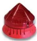
S80
Emergency signaling device with fixed light and continuous sound.
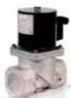
ZD...
Normally closed electromagnetic valves, with quick closing and opening, class A with approval.