
Sicurgas P11 - Gas detector Fantini Cosmi - Free user manual and instructions
Find the device manual for free Sicurgas P11 Fantini Cosmi in PDF.


| Product Type | Gas detector for methane (natural gas) |
| Brand | Fantini Cosmi |
| Model | Sicurgas P11 |
| Detection Gas | Methane (CH4) |
| Sensor Type | Semiconductor |
| Power Supply | 230V AC, 50Hz |
| Power Consumption | 4 VA |
| Alarm Threshold | 9% LIE (Lower Explosion Limit) for methane |
| Visual Alarm | Red LED (alarm), Green LED (power), Yellow LED (fault) |
| Acoustic Alarm | Built-in buzzer, selectable intermittent or continuous sound |
| Relay Output | For controlling gas valve, max 450VA at 230V AC |
| Contacts Rating | 6(2)A / 250V AC |
| Protection Degree | IP42 |
| Operating Temperature | -10°C to 40°C |
| Operating Humidity | Max 90% RH |
| Dimensions (Base) | Approx 83.5 x 60 mm |
| Installation Height | 30 cm from ceiling (for methane) |
| Test/Silence | Key with cord; press 3 sec to silence, 10 sec to test |
| Standards | EN 50194 |
| Replacement Interval | Every 5 years from installation date |
| Material | Shockproof insulating plastic |
Frequently Asked Questions - Sicurgas P11 Fantini Cosmi
User questions about Sicurgas P11 Fantini Cosmi
0 question about this device. Answer the ones you know or ask your own.
Ask a new question about this device
Download the instructions for your Gas detector in PDF format for free! Find your manual Sicurgas P11 - Fantini Cosmi and take your electronic device back in hand. On this page are published all the documents necessary for the use of your device. Sicurgas P11 by Fantini Cosmi.
USER MANUAL Sicurgas P11 Fantini Cosmi
INSTRUCTIONS FOR USE
P11-P12
GAS LEAK DETECTORS FOR METHANE AND LPG
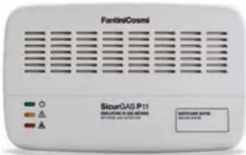
Sicurgas P11 and P12 it is a device, that through a sensitive sensor, detects methane gas concentration (P11) and LPG concentration (P12) in domestic environments.
Sicurgas P11 and P12 are operating when the gas concentration in the air is much below of the lower explosion limit (L.E.L.).
In case of alarm, interferes as well an acoustic and light alarm that is going to prevent the danger. Simultaneously Sicurgas is making the relay to interfere to control the gas interception valve.
EXISTS THE POSIBILITY THAT YOU FEEL THE GAS SMEL BEFORE THE DEVICE GIVES AN ALARM SIGNAL.
Gas detectors Sicurgas P11 and P12, when are connected to a normally closed (NC) valve with manual reset are giving positive safety. This means that the gas interception valve is closing to interrupt the inflow, as well in case of line voltage absence.
For having the maximum security can be used more gas detectors Sicurgas, connected to the same gas interception valve.
For e.g. can be mounted a P11 (P12) in the place where is installed the boiler and another one in the kitchen to control the stoves.
1 WALL MOUNTING
Sicurgas is supplied with a base suitable for mounting in built-in boxes with 3 modules or in round boxes.
Remove the base/cover retaining screw and ease off the cover.
Fix the base on the wall (see paragraph 3) or in a built-in box using rear entry for the entries of the connection cables.
ATTENTION!
DO NOT OPEN THE DEVICE, BECAUSE THIS MAY CAUSE ELECTRICAL SHOCKS OR MALFUNCTION.

ATTENTION
gas detector installation is not released from compliance with all rules regarding features, installation and use of the gas appliances, ventilation of the rooms and the discharge of the combustion products prescribed by the EN norms, implementation of the Art. 3 of the law 1083/71 and of the national legislation in force. Before installing the device, it is recommended to read carefully this instruction manual.


GREEN LED power supplied device


YELLOW LED defective detector


RED LED ALARM - gas concentration is higher than the alarm threshold
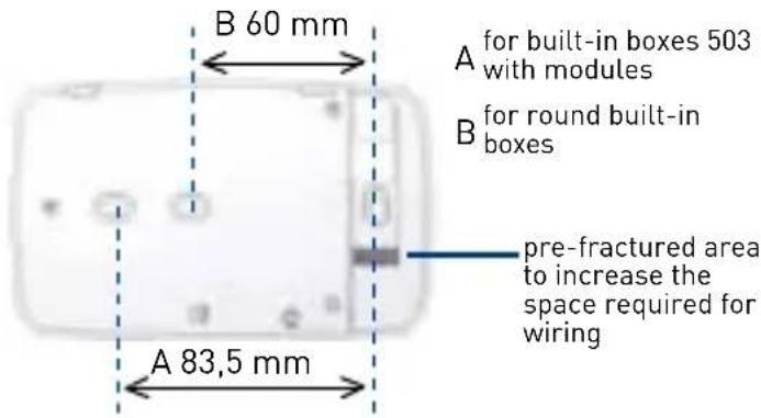
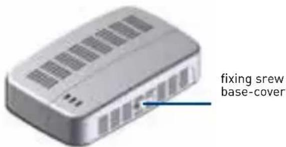
After executing the mounting and the connections (see paragraph 4) replace the cover on the base ensuring the two cover pegs are correctly located on the two latching tabs. Screw again the fixing screw and apply in the corresponding place the provided adhesive label indicating the replacement date.
FOR METHANE AND LPG
2 SICURGAS PLACEMENT
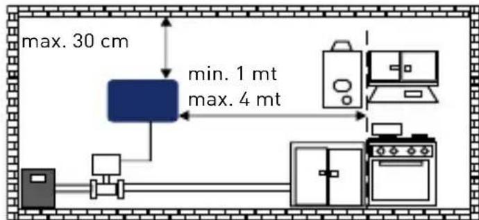
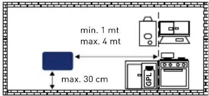
Sicurgas P11 must be fixed on the wall, about 30 cm from the ceiling and at a distance from gas user device, between a minimum of 1 meter and a maximum of 4 meters, in such position as to allow natural air circulation.
Sicurgas P12 must be installed approximately 2 meters (minimum 1m maximum 4m) from the gas user device and about 30 cm from the floor.
3 ELECTRICAL CONNECTIONS
Sicurgas P11 is already equipped with two internal alarms: one visible and one acoustic.
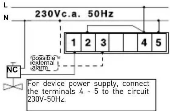
Just connect the line 230V c.a. 50Hz to the terminals 4 and 5 to ensure the gas presence signaling in the environment.
It is recommended to use a valve with manual reset to stop the gas supply when there is an alarm situation.
The internal relay can control all kind of power supplied valves with manual reset:
■ normally closed (NC), always power supplied, which require a commuting stable relay;
■ normally opened (NO), which require an impulse relay.
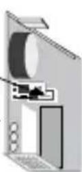
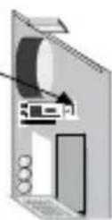
Relay operating mode can be chose in the installation moment, by moving a switch (JP6) on the printed circuit, normally supplied for functioning with stable relay for NC valves (down switch).
4 EXAMPLES OF CONNECTION
Example of connection with stable relay, always power supplied, to control a normally closed valve with manual reset (down switch).
The system guarantees maximum safety, the gas inflow will be stopped in case of:
■ gas concentration threshold exceeding;
■ power supply lack of the valve only or of the detector;
■ connection breakdown between the detector and the valve.
flowchart
graph TD
    A["Central Device"] -->|max. 30 cm| B["Upper Bound"]
    A -->|min. 1 mt max. 4 mt| C["Lower Bound"]
    C --> D["Computer"]
    C --> E["Office"]
    C --> F["Library"]
    style A fill:#66ccff,stroke:#333
    style B fill:#99ccff,stroke:#333
    style C fill:#cccccc,stroke:#333
    style D fill:#ffffff,stroke:#333
    style E fill:#ffffff,stroke:#333
    style F fill:#ffffff,stroke:#333

ATTENTION!
DO NOT place the device behind or under cabinets or shelves that are not allowing the air circulation in environment.
DO NOT place it near aerators (minimum distance 2 meters).
DO NOT place it on the vertical bakery surfaces, steam sources, in places where can be achieved by splashing water, near sinks, etc.
DO NOT place where environmental conditions are different from the prescribed operation conditions.
switch JP6 in down position (B)
predisposed in the factory stable relay for normally closed NC valves with manual reset
switch JP6 in up position (A)
impulse relay for normally opened NO valves with manual reset
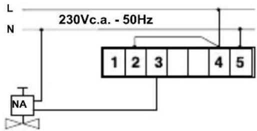
IMPULSE RELAY, WITH CURRENT ACTIVATION, TO CONTROL A NORMALLY OPENED VALVE WITH MANUAL RESET (SWITCH IN UP POSITION)
The connection will ensure the interruption of the gas inflow in case of gas concentration threshold exceeding.
USING MORE SICURGAS UNITS TO CONTROL SEVERAL ROOMS WITH ONE GAS VALVE
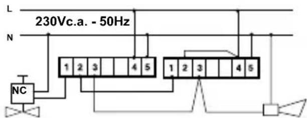
Example of connection for several Sicurgas detectors with stable relay that controls the same normally closed valve NC and an external alarm. The contacts must be connected in series.
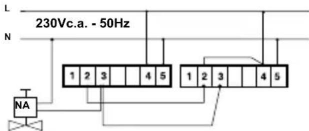
Example of connection for several Sicurgas detectors with impulse relay which controls the same normally opened valve NA. The contacts must be connected in parallel.
OPERATION
5 PLUG IN THE POWER SUPPLY (230Vc.a. 50Hz).
At the first detector switch-on and after any power supply failure, Sicurgas enters into pre-heating and a sensor stabilization phase that continues maximum 3 minutes. During this period will flash alternately the red and green led indicating that the device is not ready yet for gas detection. After this period just the green led will remain switched on.
6 DEVICE CONTROL AND SILENCING ALARM
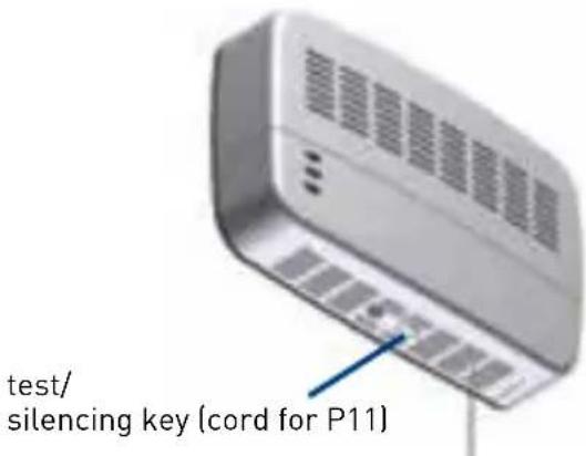
Sicurgas is provided with a TEST/SILENCING key, that allows to check the installation or to inhibit the alarm. This key is activated through a cord for P11 methane gas (installed about 30 cm from the ceiling) or through a button located on the body of P12 LPG (installed about 30cm from the floor).
To test the installation press the TEST/SILENCING key for 10 sec. In this way will be activated a control procedure of about 30 sec., during which will be checked installation components.
Alarm inhibition is used instead to avoid an involuntary intervention of the detector, in fact Sicurgas sensor, as all available on the market sensors, while being very selective can also participate for other substances, for example: alcohol vapors, wine etc.
For example, during the use of wine while preparing food is possible, that the detector will enter in alarm situation. To avoid this inconvenience press the TEST/SILENCING key for approx. 3 sec.
After having pressed the silencing key, for 10 minutes we will have a non-alarm situation: the buzzer does not emit acoustic signaling, the relay returns in non-alarm position and the red and green led, are flashing alternately to indicate the silence period; acting again on the switch during 10 minutes of the
silence period, the detector will immediately resume the normal operation.
After 10 minutes, the detector resumes automatically the normal operation.
Here is possible, knowing that can be used substances which can cause a false alarm, to reduce in advance detector's sound to prevent the signalizations and gas shut off of the stoves (due to gas valve intervention).
SOME OF THE MOST COMMON SUBSTANCES THAT CAN CAUSE FALSE ALARM ARE THE FOLLOWING: wine - liquors - alcohol - deodorants - stain-removers - varnish thinners - hair spray - excessive steam.
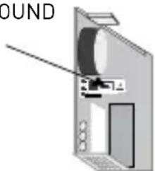
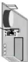
Sicurgas also allows to set the type of the acoustic alarm, see picture on the side.
INTERMITTENT SOUND switch JP3 in up position (A)
CONTINUOUS SOUND switch JP3 in down position (B)
7 MAINTENANCE AND CLEANING
Pay attention to temperature values or to the extreme humidity.
To give the maximum security the detector must be constantly powered.
For routine maintenance and for the temporary closing-down of the device, it is recommended to contact an authorized technician.
Regularly check the correct operation using the appropriate button or a gas test.
OTHER TEST METHODS MAY DAMAGE THE EQUIPMENT.
To clean the unit, use a soft cloth without using chemical cleaners or solvents.
ATTENTION! in case of alarm:
- turn off all opened flames in the room.
- close the tap of the gas meter or of the L.P.G. gas cylinder.
- do not switch on or off lights, do not operate electrical equipments or other electrically operated devices.
- open the windows and the doors to raise the ventilation inside the room.
- do not use telephones in the room where you suspect gas presence.
If the alarm stops it is necessary to identify the matter that caused it and act accordingly.
If the alarm continues and the gas leak cannot be identified or cannot be eliminated leave the room and from outside call the emergency services.
TECHNICAL FEATURES
■ Device of "A" type.
■ Shockproof insulating material casing.
■ Protection degree: IP42.
- Operating ambient temperature/humidity: from -10 to 40°C, max. 90 UR%.
■ Power supply: 230Vc.a. 50Hz.
Consumption: 4 VA.
■ Sealed relay to avoid sparks during switching.
■ Maximum power of the controlled valve: 450VA at 230Vc.a. 50Hz.
■ Contacts rating: 6(2)A / 250Vc.a.
- Switch for choosing functioning relay mode stable or impulse.
■ Semiconductor sensor for gas detection.
■ Internal visual and acoustic alarms.
■ Intervention threshold volumetric value:
- (% L.I.E.) 9% for methane.
( % L.I.E.) 10% for LPG.
In compliance with the standard EN 50194.

The symbol of the crossed-out wheeled bin indicates that the products must be collected and disposed of separately from household waste. The batteries and integrated accumulators may be disposed of together with the product. They will be separated at the recycling facilities. A black bar indicates that the product was placed on the market after 13 August 2005. Participating in the separate collection of products and batteries contributes to the correct disposal of these materials and therefore avoids possible negative consequences for the environment and human health. For more detailed information on the collection and recycling programmes available in your country, contact the local authorities or the sales point where you purchased the product.
TO BE COMPLETED BY THE INSTALLER
Installation date ____
Installation place ____
Identification code/manufacturing date
(the code is indicated inside the cover)
Sensor replacement date ____
(sensor replacement date is indicated on the front cover label)
N.B. THE DETECTOR HAS TO BE REPLACED AFTER A PERIOD OF FIVE YEARS FROM THE
INSTALLATION DATE
STAMP AND SIGNATURE OF THE INSTALLER

- INSTRUCTIONS FOR USE
- P11-P12
- GAS LEAK DETECTORS FOR METHANE AND LPG
- WALL MOUNTING
- ATTENTION!
- ATTENTION
- FOR METHANE AND LPG
- SICURGAS PLACEMENT
- ELECTRICAL CONNECTIONS
- EXAMPLES OF CONNECTION
- OPERATION
- MAINTENANCE AND CLEANING
- ATTENTION! in case of alarm:
- TECHNICAL FEATURES
- TO BE COMPLETED BY THE INSTALLER
Brand : Fantini Cosmi
Model : Sicurgas P11
Category : Gas detector