
P82 - Gas detector Fantini Cosmi - Free user manual and instructions
Find the device manual for free P82 Fantini Cosmi in PDF.


| Product Type | Gas Detector |
| Brand | Fantini Cosmi |
| Model | P82 |
| Detected Gases | Natural Gas (Methane), LPG (Propane/Butane) |
| Power Supply | 230V AC, 50Hz |
| Backup Power | Built-in rechargeable battery (optional) |
| Dimensions | 80 x 80 x 30 mm |
| Weight | 100 g |
| Alarm Type | Audible (85 dB) and visual (LED) |
| Alarm Threshold | 10% LEL for methane, 20% LEL for LPG |
| Operating Temperature | -10°C to +50°C |
| Humidity Range | 0% to 95% RH (non-condensing) |
| Mounting | Wall-mount, indoor use |
| Self-Test Function | Yes, manual test button |
| End-of-Life Indicator | Yes, after 10 years |
| Maintenance | Clean with a soft, dry cloth; test monthly |
| Certifications | CE, EN 50194 |
Frequently Asked Questions - P82 Fantini Cosmi
User questions about P82 Fantini Cosmi
0 question about this device. Answer the ones you know or ask your own.
Ask a new question about this device
Download the instructions for your Gas detector in PDF format for free! Find your manual P82 - Fantini Cosmi and take your electronic device back in hand. On this page are published all the documents necessary for the use of your device. P82 by Fantini Cosmi.
USER MANUAL P82 Fantini Cosmi
The P82 control unit can be used to connect up to four detectors (model S81-82-83 or S84-85-86.) to create gas detection systems in environments such as boiler rooms, workshops, warehouses, laboratories etc.; the incorporated alarm relay can be used to control a solenoid valve or an accessory device (siren, flashing light, extractor, etc.). The installation of a gas or carbon monoxide detection system does not constitute a release from compliance with all regulations for the installation and use of gas devices and with the relative safety standards and legal provisions in force for this kind of system. Installation, periodic inspections and maintenance of devices and systems must be carried out by qualified service technicians.
TECHNICAL SPECIFICATIONS
P82 CONTROL UNIT (data with S84-85-86.. detectors in brackets)
Power supply: 12Vac/dc ± 10%
Consumption with 1 detector: about 160mA (320mA)
Consumption with 4 detectors: about 280mA [920mA]
Connections: 2 terminals of 2,5 mm ^4
Protection: power input fuse 1A 5x20mm
Ingressi: n.4 for S81, S82, S83 detectors, or S84-85-86
detectors (different types of gas)
Detector terminations:: 3 terminals of 2.5 mm² per detector:
C [-12...24V]; S [+4...20mA]; A [+12...24V]
Max cable run length: 50 m for each detector
Diameter of the 3 wires: 1,5 mm²
Alarm output: 1 relay with one contact SPDT 8A 250Vacc
Failure output: 1 relay with one contact SPDT 8A 250Vac
Output connections: 3 terminals of 2.5mm^2 for C-NC-NO relay.
Visual alarms: 1 green LED: power on
1 yellow LED: general abnormality
4 yellow LEDs: failure for each detector line
4 red LEDs: gas alarm for each detector line
Audible alarms: 1 buzzer noise level > 60db at 1m
"Reset/Test" button: 1 for alarm reset and detector test
Enclosure: RAL7035 grey, self-extinguishing plastic house
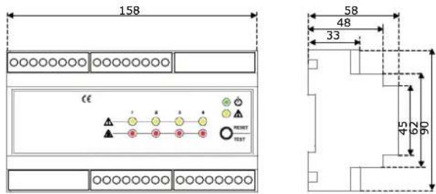
Dimensions: 158x90x58 mm (9 modules DIN 43880)
Weight: 250 g
Mounting: Back panel Omega DIN rail (EN 50022)
Protection rating: IP20; IP40 when correctly installed in
electric panel
Room temperature: 0 - 50 °C
Humidity: ≤90% U.R. (non condensing)
CE Conformity
Product standards: Standards EN 61779-1-4; CEI 216-5/1
EMC Directives/Standards EMC EMC 89/336/CEE, Standards EN 50270
S81-82-83 (S84-85-86) DETECTORS
Power supply: from the P82 control unit
Consumption: 40mA (200mA)
Connections: 3 terminals of 2.5mm^2 per detector:
C [-12...24V]; S [+4...20mA]; A [+12...24V]
Models: Methane gas S81, LPG S82,
Carbon monoxide S83
Models URx20... Various gases, see dedicated data sheet
Calibration:: S81: 10% LIE di Methane
(S8x...: 20% LIE combustibles,, 100ppm CO)
Enclosure: self-extinguishing plastic house
Dimensions: 66x90x45 mm (depending on model)
Weight: 65 g
Mounting: wall-mounted using plastic screws and anchors
Protezione IP44 (IP44, IP55 o IP65 depending on model)
Room temperature: 0 ÷ 50^ (-20 ÷ +50°C)
Humidity: ≤90% U.R. (non condensing)
LV Directives/Standards Not applicable
EMC Directives/Standards EMC 89/336/CEE, Standard EN 50270
OTHER FEATURES OF S84-85-86.. DETECTORS
See technical features on dedicated data sheet.
MOUNTING
Ensure correct environmental conditions (see technical specifications).
CONTROL UNIT P82
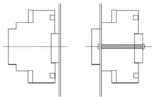
To guarantee the correct protection rating for the device it must be installed in an electric panel manufactured according to the laws in force for workplaces and that can also house the power supply system. Mount the control unit on an omega DIN rail (to DIN EN 50022), using accessories for standard electric panels. It can be installed on a mounting plate or in DIN rail modules.
natural_image
Pure technical line drawing of two mechanical or architectural components without any text, numbers, or symbolsS81-82-83 (S84-85-86) DETECTORS
To be used for wall-mounting (vertical), attached by plastic screws and anchors. To install, insert a screwdriver in the recess at the bottom of the enclosure to open it; avoid damage to the sensor and do not touch the calibration devices. The detectors must be correctly positioned for the system to operate properly. For this purpose, the control units must be installed:
• in zones with constant natural air circulation
- in zones free of dust and dirt that could clog up the sensor and make it ineffective
- never near running water, exhaust vents, windows, openings etc.
- at a suitable distance from gas-fuelled equipment to avoid the system taking inappropriate action due to possible functional loss.
The positioning also depends on the type of gas that is to be detected, in particular:
• S81: Methane gas - high, about 20-30 cm from ceiling
• S82: LPG - low, about 20-30 cm from floor
• S83: CO - about 1.5 m from floor
For new plants, the detectors must be installed at the last possible moment so that typical worksite activities (particularly welding, painting, sealing etc.), do not damage the actual detectors (particularly the sensitive part).
S84-85-86.. DETECTORS
See installation instructions on dedicated data sheet.
ELECTRICAL CONNECTIONS
Normal electric cables can be used. Still, if detectors are to be installed in environments with high exposure to EMI, it is advisable to use shielded cables. The detection system must always be operating, so power switches or other devices that could inadvertently make the detector inoperative must not be used. Do not touch the sensing element and the electronic circuits for any reason whatsoever. Tampering of any kind may cause the system to operate incorrectly.
Ensure compliance with all current electric standards.
P82 CONTROL UNIT
The control unit must be powered at 12 Vac/dc; use transformers with double insulation, sized for uninterrupted use for the power utilised (See Technical specifications). For connecting the relay outputs use wires with a minimum diameter of 1.5 mm^2 . Prepare wiring connections according to the electrical diagrams contained in these instructions.
S81-82-83 OR S84-85-86 DETECTORS
Prepare wiring connections according to the electrical diagrams contained in these instructions, using wires with a minimum diameter of 1.5 mm^2 for a maximum length of 50 m for each detector.
COMMISSIONING
The P82 control unit and the S81-82-83 or S84-85-86 detectors are safety control devices, therefore they must not be tampered with; do not touch the sensor or the electronics for any reason whatsoever. Carry out the following controls:
- the power supply for the control unit must comply with the values provided (12 Vac/dc ± 10%)
- make sure the power consumed by any devices connected to the relay terminals is below or the same as the maximum capacity of the contacts (see TECHNICAL SPECIFICATIONS)
- if there are no detectors on the respective control unit terminals, resistances 18 KOhm 14 W 5% are supplied as standard [terminals C and S]. In any case, these terminals must be disconnected from the inputs where there are detectors
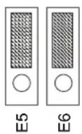
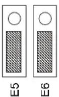
- the detectors must be compatible with the type of gas to monitor and correctly connected to the control unit. Depending on the type of detector to connect, jumper pairs E5-E6, E7-E8, E9-E10, E11-E12 must be positioned for each detector as follows (example for detector 1):
Position A (default) per sonda S81-82-8
Position B per sonda S84-S85-S86
A
B
A
B
WARNING
To enable the URx20.. sensors to operate, it is also necessary to set jumpers E3 and E4 as instructed in the chapter: description of device.
- the operating mode (positive or negative logic) selected must be consistent with the system choices. As regards this, check the position of Jumper E1 (see OPERATION)
- the operating mode selected for the relays must be consistent with the system choices. As regards this, check the position of Jumper E2 (see OPERATION)
- test the gas alarm and abnormal detector event on the detectors connected (see OPERATION).
OPERATION
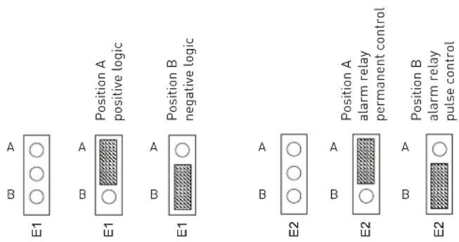
The Jumper E1 can be used to select the operating mode (positive or negative logic). The control unit signals its operating status through LEDs. Depending on the operating mode selected through Jumper E1, in a normal situation (no alarm), the LEDs and the
relays are as follows:
• positive operating logic: LEDs on; relays energised
- negative operating logic: LEDs off; relays de-energised
If the negative operating logic is selected, the alarm relay can be permanently or impulse controlled, depending on the position of Jumper E2:
Once the correct power is supplied, the control unit carries out the following phases in sequence:
LED AND BUZZER TESTS (ABOUT 5 SECONDS)
Whichever operating mode is selected, the LEDs will switch on in sequence and the buzzer will sound briefly.
WARM-UP OF DETECTORS (ABOUT 1 MINUTE)
During this phase, which brings the detectors up to the correct operating temperature, the gas detection system is not operational. During this phase, if the wiring connections are correct, the control unit display shows the following:
| INTERFACE Positive logic | Negative logic | ||
| Power supply LED Green R | flashing 1 Hz | Flashing 1 Hz | |
| General failure LED | Yellow On | Off | |
| Detector failure LED (4) | Yellow On | Off | |
| Alarm and line failure LED (4) | Red | On | Off |
| Alarm buzzer | No sound | No sound | |
| Alarm relay Energised | De-energised | ||
| Failure relay | Energised | De-energised | |
OPERATING TEST (ABOUT 3 MINUTES)
Once the detector warm-up phase is complete, the device enters the operating test phase. During this phase, all internal timing is reset to ease operating verification of the detectors (alarm simulation). In this case, the control unit display shows the following:
| INTERFACE | Positive logic Negative logic | ||
| Power supply LED Green | Flashing | 2 Hz | Flashing 2 Hz |
| General failure LED | Yellow | On | Off |
| Detector failure LED (4) | Yellow | On | Off |
| Alarm and line failure LED (4) | Red | On | Off |
| Alarm buzzer | No sound | No sound | |
| Alarm relay | Energised | De-energised | |
| Failure relay | Energised | De-energised | |
Keep the "Reset/Test" button pressed down for over 1 second to interrupt the operating test phase. To test the detectors correctly, proceed as follows:
GAS ALARM TEST
Bring the test cylinder close to the detector grille and release a small amount of gas [caution: if the gas is aimed directly at the sensor, this will be permanently damaged]. For CO testing of detectors, smoked produced by combustion can be used. The control unit will signal the alarm as follows:
| INTERFACE | Positive logic Negative logic | ||
| Detector alarm LED | Red | Off | On |
| Alarm buzzer | Continuous sound | Continuous sound | |
| Alarm relay | De-energised | Energised[permanently or pulsed depending on E2] | |
Keep the "Reset/Test" button pressed down for over 1 second to silence the alarm (if there is no gas remaining) and terminate the operating test phase. To restart the Test phase, just keep the relative button pressed down for about 6 seconds. Repeat the operations described above to test the other detectors.
CAUTION
The repeated use or high concentration of interfering substances (alcohol, lighter fluid etc.) can cause permanent damage to the sensor and put the device out of service.
DETECTOR FAILURE TEST
Simulate a failure in the detectors as follows:
- disconnect the cable of a detector and verify the following alerts:
| INTERFACE Positive logic Negative | logic | ||
| Detector failure LED Yellow Off On | |||
| Alarm buzzer Intermittent | sound | Intermittent sound | |
| Failure relay De-energised | Energised | ||
| General failure LED | Yellow On | Off | |
- reconnect the detector and press the "Reset/Test" to return the control unit to normal operating mode, making sure the conditions of the various interfaces are reset.
NORMAL OPERATION
This is the normal operating phase of the control unit during which both gas alarm monitoring and self-testing of the instruments (detectors) and the system (control unit) are active. During this phase, where there are no alarms and/or abnormalities, the control unit display shows the following:
| INTERFACE | Positive logic | Negative logic | |
| Power supply LED | Green | On | On |
| General failure LED | Yellow | On | Off |
| Detector failure LED (4) | Yellow | On | Off |
| Alarm and line failure LED (4) | Red | On | Off |
| Alarm buzzer | No sound | No sound | |
| Alarm relay | Energised | De-energised | |
| Failure relay | Energised | De-energised | |
When dangerous concentrations of gas are detected, the control unit enters the gas alarm phase and carries out the following operations:
| INTERFACE | Positive logic Negative logic | ||
| Detector alarm LED | Red | Off On | |
| Alarm buzzer | Continuous sound | Continuous sound | |
| Alarm relay | De-energised | Energised (permanently or pulsed depending on E2) | |
Once the gas alarm condition is normalised, the control unit needs to be reset to its normal operating status. Press the "Reset/Test" button on the front of the control unit to reset it. If there are abnormalities (detectors and/or control unit), the control unit will show the following display:
| INTERFACE | Positive logic | Negative logic | |
| General failure LED(for control unit failure) | Yellow | Off | On |
| Detector failure LED(for detector failure) | Yellow | Off | On |
| Alarm buzzer | Intermittent sound | Intermittent sound | |
| Failure relay | De-energised Energised | ||
Once the failure is fixed, the control unit needs to be reset to its normal operating status. Press the "Reset/Test button on the front of the control unit to reset it.
Caution: it is advisable to repeat the operating test at least once a year, or after a prolonged period of stoppage and in any case, every time the detector is replaced.
CAUTION
The average lifetime of the S81-82-83 and S84-85-86.. detectors is 5 years from installation date. They must be replaced before the end of the 5th year of use. The average lifetime of detectors is calculated for use in a typical environment, normally free from polluting agents (gases, solvents etc.). More frequent and higher concentrations of these substances can accelerate the normal oxidisation process of the sensing element, subsequently shortening its lifetime.
GAS ALARM
If an alarm signals a gas leak or the presence of carbon monoxide, proceed as follows:
- put out flames and switch off all gas equipment
- do not for any reason switch on or off lights or any electrical equipment
- open doors and windows to air the environment
- look for and eliminate the cause of the alarm. If this is not possible, leave the building and contact emergency services from outside.
ENVIRONMENTAL COMPATIBILITY AND DISPOSAL
This product has been designed and constructed using materials and processes that take into account the environmental impact. Refer to the following notes for disposal of the product at the end of its working life, or when it is replaced:

- for disposal purposes, this product is classified as an electric and electronic device: do not dispose of it with normal household waste, in particular as regards the printed circuit,
• comply with all local laws in force - as far as possible reuse basic materials to keep environmental impact to a minimum.
- use local depots and waste recycling companies, or contact the supplier or manufacturer to return used products or to ask for information on environmental compatibility and waste disposal,
- the product packaging can be reused. Keep it for future use or to return the product to the supplier.
TROUBLESHOOTING
| PROBLEM | POSSIBLE CAUSE |
| NC valve does not open | Valve not connectedAlarm in progressDetector warm-up phase in progressAll detectors defectiveGeneral failure event occurring |
| NO valve does not close | Valve not connectedConnection cables cutNo alarm active |
| "Reset/Test" button does not reset to initial conditions | Alarm in progressAbnormal event occurring in control unit |
| On | Off |
| No sound | No sound |
| Energised De-energised | |
| Energised De-energised |
TERMINAL BOARD
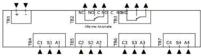
flowchart
graph TD
    TB1["+ -"] --> TB2["NC NO C NO C NONC"]
    TB2 --> TB3["TC"]
    TB3 --> TB4["C1 S1 A1"]
    TB4 --> TB5["C2 S2 A2"]
    TB5 --> TB6["C3 S3 A3"]
    TB6 --> TB7["C4 S4 A4"]
    TB4 --> Allarme_Annalie
    TB5 --> Allarme_Annalie
    TB6 --> Allarme_Annalie
    TB7 --> Allarme_Annalie
+ Power supply 12 Vac/dc (positive)
- Power supply 12 Vac/dc (negative)
C Alarm Alarm relay output (common)
NC Alarm Alarm relay output (normally closed contact)
NO Alarm Alarm relay output (normally open contact)
C Abnormality Alarm relay failure (common)
NC Abnormality Alarm relay failure (normally closed contact)
NO Abnormality Alarm relay failure (normally open contact)
S81-82-83 DETECTOR CONNECTIONS
C1,C2,C3,C4, detector input (C, common)
S1,S2,S3,S4, detector input (S, signal)
A1,A2,A3,A4, detector input (A, power supply 6,5V)
S84-85-86.. DETECTOR CONNECTIONS
C1,C2,C3,C4, detector input (-12...24V, negative power supply/signal)
S1,S2,S3,S4, detector input (+4...20mA, positive signal)
A1,A2,A3,A4, detector input (+12...24V, positive power supply/signal)
DESCRIPTION OF GAS DETECTION CONTROL UNIT
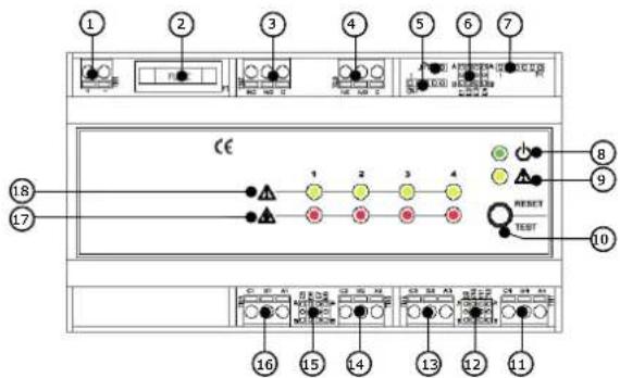
- TB1 - Power supply terminals 12 Vac/dc
- Protection fuse 1A
- TB2 - "Alarm" relay terminals
- TB3 - "Abnormality" relay terminals
- CN1 connector and service
- Jumper J1 Jumper di set-up:
E1 - operating mode
E2 - alarm relay operating mode
E3 - omitted=S81-82-83 on inputs 1 and 2 A=S84-85-86.. on input 1, B=S84-85-86.. on inputs 1 and 2
E4 - omitted=S81-82-83 on inputs 3 and 4 A=S84-85-86.. on input 3, B=S84-85-86.. on inputs 3 and 4
- Connector P1 (communication - not used)
- LED signalling presence of voltage
- LED signalling general failure
- Reset/Test button
- TB7 - B4 gas detector connection terminals
- Jumper E11, E12 for configuration of inputs B4 detector: E11 - Sel. power supply: A=6.5V (S81-82-83), B=12V (S84-85-86) E12 - Sel. input A=threshold (S81-82-83), B=4...20mA (S84-85-86..) Jumper E9, E10 for configuration of inputs B3 detector: E9 - Sel. power supply: A=6.5V (S81-82-83), B=12V (S84-85-86) E10 - Sel. input A=threshold (S81-82-83), B=4...20mA (S84-85-86..)
- TB6 - B3 gas detector connection terminals
- TB5 - B2 gas detector connection terminals
- Jumper E7, E8 for configuration of inputs B2 detector: E7 - Sel. power supply: A=6.5V (S81-82-83), B=12V (S84-85-86) E8 - Sel. input A=threshold (S81-82-83), B=4...20mA (S84-85-86...) Jumper E5, E6 for configuration of inputs B1 detector: E5 - Sel. power supply: A=6.5V (S81-B2-83), B=12V (S84-85-86) E6 - Sel. input A=threshold (S81-82-83), B=4...20mA (S84-85-86...)
- TB4 - B1 gas detector connection terminals
- Gas alarm LED
- Detector failure LED
CONNECTION DIAGRAMS
4-module control unit (2 S84-85-86.. and 2 S81-82-83 connectors) and NO solenoid valve. External failure signalling. Negative mode.
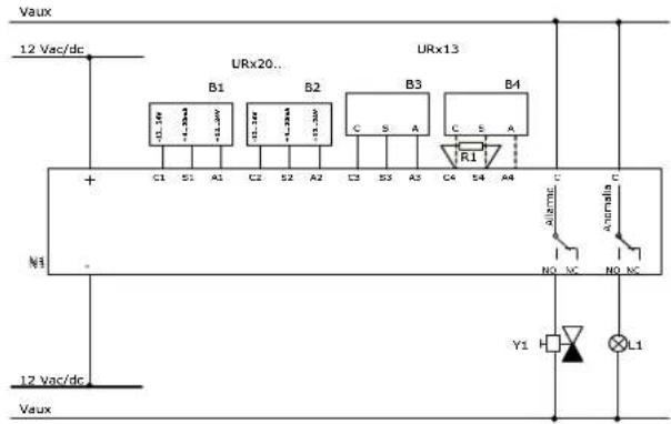
N1 P82 control unit
B1-B2 S84-85-86.. detectors
B3-B4 S81-82-83 detectors
Y1 NO gas solenoid valve (Vaux: 24, 230Vac)
L1 Failure signalling device
R1 Resistance 18 KOhm ¼W (in the absence of B4 detector)
DIMENSIONS
P82 control unit
S81-82-83 DETECTORS
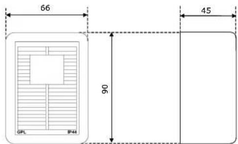
S84-85-86.. DETECTORS
Depending on model (see dedicated technical data sheet).
| INSTALLATION DATA | INSTALLER'S STAMP |
| Control unit replacement date: | |
| Detector replacement date: | |
| Detector 1: | |
| Detector 2: | |
| Detector 3: | |
| Detector 4: |
- TECHNICAL SPECIFICATIONS
- S81-82-83 (S84-85-86) DETECTORS
- MOUNTING
- CONTROL UNIT P82
- S84-85-86.. DETECTORS
- ELECTRICAL CONNECTIONS
- P82 CONTROL UNIT
- S81-82-83 OR S84-85-86 DETECTORS
- COMMISSIONING
- WARNING
- OPERATION
- LED AND BUZZER TESTS (ABOUT 5 SECONDS)
- WARM-UP OF DETECTORS (ABOUT 1 MINUTE)
- OPERATING TEST (ABOUT 3 MINUTES)
- GAS ALARM TEST
- CAUTION
- DETECTOR FAILURE TEST
- NORMAL OPERATION
- GAS ALARM
- ENVIRONMENTAL COMPATIBILITY AND DISPOSAL
- CONNECTION DIAGRAMS
Brand : Fantini Cosmi
Model : P82
Category : Gas detector