
EB-1420WI - Interactive projector EPSON - Free user manual and instructions
Find the device manual for free EB-1420WI EPSON in PDF.
| Product type | Interactive projector |
| Brand | EPSON |
| Model | EB-1420WI |
| Interactive function | Easy Interactive Function with pen |
| Pen calibration | Manual and automatic |
| Mounting | Wall mount with included installation plate |
| Projection distance | 6.2 to 31.1 cm (depending on image size) |
| Maximum image size | 100 inches (16:10 aspect ratio) |
| Supported image formats | 4:3, 16:9, 16:10 |
| Connections | USB-A, USB-B, Computer (VGA), Audio, LAN, Remote, port SYNC |
| Control Pad power supply | 2 AA batteries or via projector (optional kit) |
| Included batteries | 2 AA batteries |
| Installation plate weight | Approximately 8.1 kg |
| Control Pad weight | Approximately 240 g (without batteries) |
| Included accessories | Installation plate, Control Pad, pen, USB cable, power cord, batteries, cable covers |
| Image adjustments | Vertical slide (±38 mm), horizontal slide (±45 mm), forward/backward (0-360 mm), roll (±3°), horizontal rotation (±8°), vertical tilt (±3°) |
| Batch configuration function | Via USB key (FAT format) |
| Security | Kensington anti-theft lock compatible, safety instructions in the manual |
| Operating temperature (Control Pad) | 0 to +50°C (non-condensing) |
Frequently Asked Questions - EB-1420WI EPSON
User questions about EB-1420WI EPSON
0 question about this device. Answer the ones you know or ask your own.
Ask a new question about this device
Download the instructions for your Interactive projector in PDF format for free! Find your manual EB-1420WI - EPSON and take your electronic device back in hand. On this page are published all the documents necessary for the use of your device. EB-1420WI by EPSON.
USER MANUAL EB-1420WI EPSON
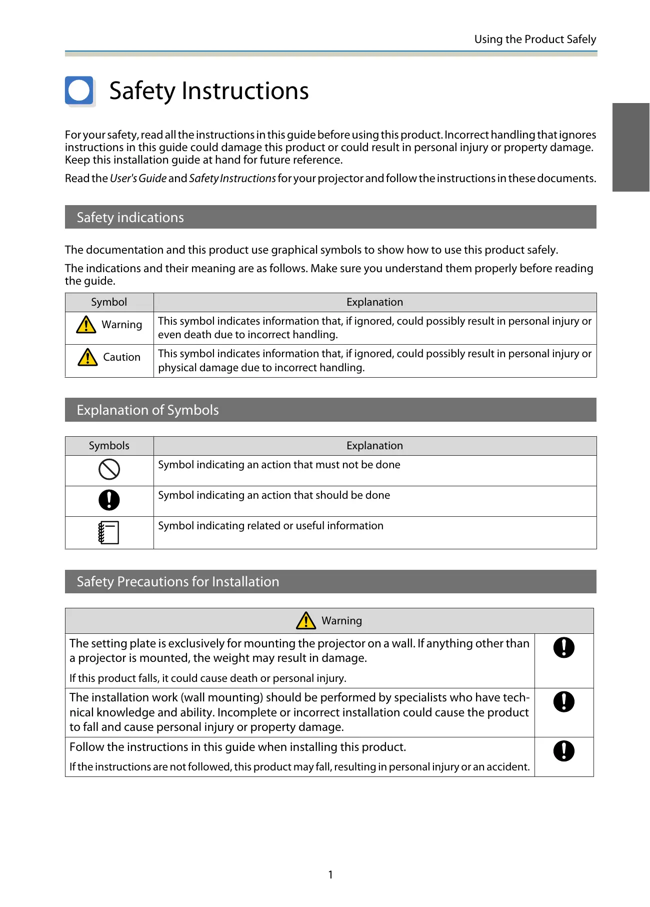
For your safety, read all the instructions in this guide before using this product. Incorrect handling that ignores instructions in this guide could damage this product or could result in personal injury or property damage. Keep this installation guide at hand for future reference.
Read the User's Guide and Safety Instructions for your projector and follow the instructions in these documents.
Safety indications
The documentation and this product use graphical symbols to show how to use this product safely.
The indications and their meaning are as follows. Make sure you understand them properly before reading the guide.
| Symbol | Explanation |
| Warning | This symbol indicates information that, if ignored, could possibly result in personal injury or even death due to incorrect handling. |
| Caution | This symbol indicates information that, if ignored, could possibly result in personal injury or physical damage due to incorrect handling. |
Explanation of Symbols
| Symbols | Explanation |
| ∅ | Symbol indicating an action that must not be done |
| ! | Symbol indicating an action that should be done |
| - | Symbol indicating related or useful information |
Safety Precautions for Installation
| Warning | |
| The setting plate is exclusively for mounting the projector on a wall. If anything other than a projector is mounted, the weight may result in damage. If this product falls, it could cause death or personal injury. | ! |
| The installation work (wall mounting) should be performed by specialists who have technical knowledge and ability. Incomplete or incorrect installation could cause the product to fall and cause personal injury or property damage. | ! |
| Follow the instructions in this guide when installing this product. If the instructions are not followed, this product may fall, resulting in personal injury or an accident. | ! |
| Handle the power cord carefully. Incorrect handling may cause fire or electric shock. Observe the following precautions when handling: Do not handle the power plug with wet hands. Do not use a power cord that is damaged or modified. Do not pull the power cord with too much force when routing the cable through the setting plate. | ! |
| Do not install the setting plate in a place where it might be subjected to vibration or shock. This could cause damage to the product or mounting surface. If this product falls, it could cause death or personal injury. | ○ |
| Install the setting plate so that it can sufficiently support the mass of the projector and setting plate, and resist any horizontal vibration. Use M10 nuts and bolts. Nuts and bolts smaller than M10 could cause the setting plate to fall. Epson accepts no responsibility for any damage or injury caused by lack of wall strength or inadequate installation. | ○ |
| The installation work should be performed by at least two qualified service personnel. If you need to loosen any screws during installation, be careful not to drop this product. If this product falls, it could cause death or personal injury. | ○ |
| When mounting this product on a wall, the wall requires enough strength to hold the projector, the setting plate, the Control Pad, and the Touch Unit (EB-1430Wi only). This product should be installed on a concrete wall. The maximum combined weight of the projector, the setting plate, and the Control Pad is approximately 14 kg (not including cables). When the Touch Unit (EB-1430Wi only) is installed, the maximum weight is approximately 14.5 kg (not including cables). Ensure the strength of the wall before mounting this product on the wall. If the wall is not strong enough, reinforce the wall before installation. | ○ |
| Inspect the setting plate on a regular basis to ensure there are no broken parts or loose screws. If any parts are damaged, stop using the setting plate immediately. If this product falls, it could cause death or personal injury. | ○ |
| Do not disassemble or remodel this product. There are numerous high-voltage sections inside the product that could cause a fire, electric shock, or an accident. | ○ |
| Do not hang on this product or hang a heavy object on this product. If this product falls, it could cause death or personal injury. | ○ |
| Do not use adhesives, lubricants, or oils to install or adjust the setting plate. If you use adhesives to prevent the screws from loosening or things such as lubricants or oils on the slide plate fixing part of the projector, the case may crack and cause the projector to fall, resulting in personal injury or property damage. | ○ |
| Tighten all screws firmly after adjustment. Otherwise, the product may fall and cause personal injury or property damage. | ○ |
| Never loosen the bolts and nuts after installation. Confirm that the screws have not become loose on a regular basis. If you find any loose screws, tighten them firmly. Otherwise, the product may fall and cause personal injury or property damage. | ○ |
| Route the cables so that they do not interfere with the nuts and bolts. Incorrect handling of the cables may cause fire or electric shock. | ○ |
| When turning on the projector, do not look into the projection window. This could cause damage to eyesight due to the powerful light emitted. Take particular care when there are children present. When turning on the projector at a distance using the remote control, make sure there is no one looking into the projection window. | × |
| When using the projector, do not place any objects or put your hand near the projection window. This area is dangerous as it reaches a high temperature due to the concentrated projection light. | × |
| Do not cover the projector's air intake vent or air exhaust vent. If either of the vents are covered, the internal temperature could rise and cause a fire. Avoid locations subject to high temperatures, such as close to heaters, and leave a gap of at least 20 cm between the wall and the air exhaust vent. | × |
| Do not use the projector in a location subject to combustible or explosive gas. The projector may catch fire because of the high temperature of the lamp inside the projector. | × |
| If any abnormalities occur with this product, immediately disconnect the cables from the product, and then contact your local dealer or the nearest Epson service call center. Continuing to use the product in an abnormal condition could cause a fire, electric shock, or visual impairment. | × |
| Caution | |
| Do not install this product in a location where the operating temperature for your projector model may be exceeded. Such an environment may damage the projector. | × |
| Install this product in a place free from excessive dust and humidity to prevent the lens or optical components from becoming dirty. | × |
| Do not use excessive force when adjusting this product. This product may break, resulting in personal injury. | × |
Notes on handling the Touch Unit (EB-1430Wi only)
| Warning | |
| Do not disassemble or remodel the Touch Unit. The Touch Unit contains a high power laser product that could cause a fire, electric shock, or an accident. | ○ |
| Follow the instructions in this guide to setup and operate the Touch Unit. If the Touch Unit is not setup and operated correctly, it could cause damage to eyesight due to light from the laser. | ○ |
| Do not apply optical devices such as a magnifying glass or telescope to the laser light diffused from the Touch Unit. Using it in this condition could have a negative influence on the human body. It could also cause a fire or accident. | ○ |
| Do not look into the Touch Unit's laser diffusion ports. This could cause damage to eyesight due to the powerful laser light emitted. Take particular care when there are children present. | ⊗ |
| Do not view the laser light using optical devices such as a magnifying glass within a range of 70 mm from the Touch Unit's laser diffusion ports. This could cause visual impairment. | ⊗ |
| Only connect the Touch Unit to the EB-1430Wi. Do not connect it to any other projectors or devices. The device could malfunction, or laser light could leak beyond its restricted area. | ⊗ |
| Do not go near the Touch Unit if you are using medical equipment such as a pace maker. Furthermore, when using the Touch Unit, make sure there is no one using medical equipment such as a pace maker, in the surrounding area. A powerful magnet within the unit generates electromagnetic interference which may cause medical equipment to malfunction. | ◇ |
| Caution | |
| Do not go near the Touch Unit with magnetic storage media such as magnetic cards, or precision electronic devices such as computers, digital watches, or mobile phones. A powerful magnet within the unit could corrupt data or cause a malfunction. | ⊗ |
About This Installation Guide
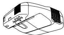
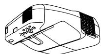
This guide describes how to mount the short-throw projector EB-1430Wi/EB-1420Wi on a wall. It also explains how to install the Control Pad and the Touch Unit (EB-1430Wi only) after mounting on a wall.

Choosing an Installation Location
Projector installation location
- Carry out power supply wiring work for the installation location of the setting plate in advance.
- Install the projector away from other electric devices such as fluorescent lights or air conditioners. Some kinds of fluorescent lights could interfere with the remote control of the projector.
- It is recommended to keep connection cable length less than 20 meters to reduce external noise.
- We recommend using stick-on screens or board screens.
-
Make sure the projector is installed under the following conditions.
-
The projected image is a rectangular shape without any distortion.
-
The projector is tilted at an angle of no more than ± 3^ vertically and horizontally in relation to the screen.
-
When using the interactive function (Easy Interactive Function), install so that the projected image is within reach.
- Do not install the projector or the screen in a location subject to direct sunlight. If the projector or the screen are subject to direct sunlight, the interactive function may not operate correctly.
Control Pad installation location
When powering the Control Pad using batteries, make sure the installation location meets the following requirements.
- Install the Control Pad on the same surface as the projection screen.
If the projection screen and the Control Pad installation point are uneven, install the Control Pad approximately 20 cm from the edge of the screen. - Make sure there are no obstacles between the Control Pad and the projector (not including the Touch Unit).
In the following situations, use the optional Remote control cable set (ELPKC28) to supply power to the Control Pad from the projector.
- When the requirements mentioned above are not met.
- When the projection screen and the Control Pad installation point are uneven and the difference in height is more than 5 ~cm
- When the projector is placed on a table and projecting to the screen.
- When multiple projectors are being used.
Touch Unit installation location (EB-1430Wi only)
-
When using the Touch Unit, install the projector using one of the following methods. The Touch Unit cannot be used if another installation method is used.
-
Mount the projector on a wall or suspend it from a ceiling and project images from in front of the screen.
-
Install vertically on a table and project from the front of the table. (When installing vertically on a table, you need the optional Interactive Table Mount (ELPMB29).)
-
Before installing the Touch Unit, make sure that the installation location meets the following conditions.
-
The Touch Unit can be secured with magnets or with screws.
- A flat, smooth, unwarped surface with no unevenness on the screen surface of more than 5 ~mm .
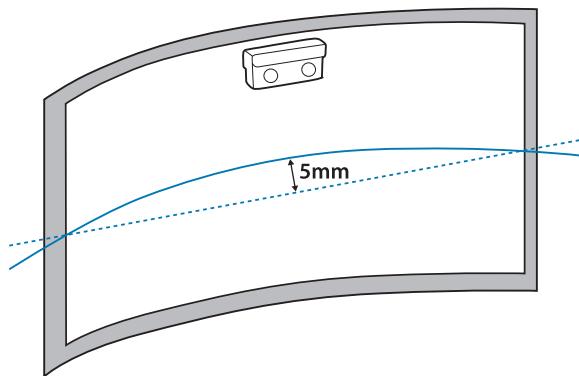
- When installing on a whiteboard, install the Touch Unit within the frame of the whiteboard.
| Correct installation position | Incorrect installation position |
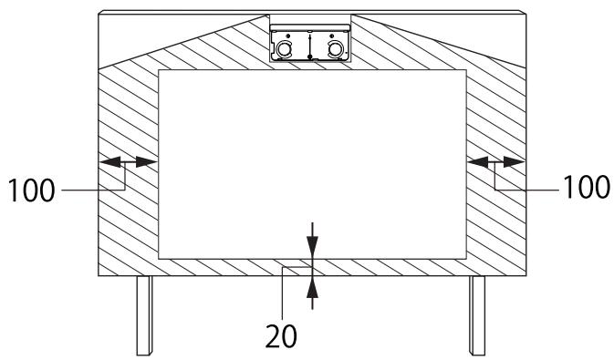
- When installing the Touch Unit, make sure there are no obstacles, such as cables, or protruding items such as whiteboard trays, holders, or thick frames in the shaded areas in the following figure. The Touch Unit will not operate correctly.
[Unit: mm]
Using the Product Safely
Safety Instructions 1
Safety indications 1
Explanation of Symbols 1
Safety Precautions for Installation 1
Notes on handling the Touch Unit (EB-1430Wi only) 3
About This Installation Guide 4
Choosing an Installation Location 5
Projectile installation location 5
Control Pad installation location 5
Touch Unit installation location (EB-1430Wi only) 5
Installation Guide
Installation Work Flow 9
Package Contents 10
Setting plate 10
Control Pad 11
Touch Unit (EB-1430Wi only) 11
Specifications 12
Setting plate 12
Wall plate 12
Vertical slide adjustment range 13
Horizontal slide adjustment range 13
Forward/backward slide adjustment range 13
Control Pad 14
Control Pad (external dimensions/weight) 14
Cable routing holes 14
Touch Unit (EB-1430Wi only) 15
Touch Unit (external dimensions/weight) 15
Attached labels 15
Projection Distance Table 17
Figures of Installation Dimensions 17
When installing the Touch Unit (EB-1430Wi only) 17
When installing the Control Pad 19
When Projected Image is Smaller than 75 Inches 20
16:10 projected image 21
16:9 projected image 21
4:3 projected image 22
When Projected Image is Larger than 75 Inches 23
16:10 projected image 24
16:9 projected image 25
4:3 projected image 25
Installing the Setting Plate 27
Connecting Devices 27
Necessary cables 27
Installation Procedure 30
Disassemble the parts 30
Assemble the parts 30
Install the wall plate on the wall 32
Determine the projection distance, and then pass the cables through the setting plate 34
Attaching the setting plate to the wall plate 36
Securing the projector to the setting plate 38
Adjusting the Projected Image 40
Adjusting the Projection Position 40
Fine-tuning the Focus 46
Calibrating the pen 47
Attaching the Covers 51
Installing the Control Pad 53
Installation Procedure 53
Installing the Touch Unit (EB-1430Wi only) 56
Installation Procedure 56
Angle Adjustment 60
Touch Calibration 71
Appendix
Batch Setup Function 75
Saving settings to the USB flash drive 75
Reflecting saved settings to other projectors 76
When Setup Fails 77
Using the Interactive Function when
Multiple Projectors are Installed 79
Attaching a Security Cable 80
General Notice 81

Installation Work Flow
Follow the procedures below to mount the projector on a wall.
1 Installing the Setting Plate and the Projector (p.27)
2 Adjusting the Projected Image (p.40)
3 Calibrating the Interactive Pen (p.47)
4 Installing the Control Pad (p.53)
When installing the Touch Unit, finish installing the projector first, and then follow the procedures below (EB-1430Wi only).
1 Installing the Touch Unit (p.56)
Adjusting the Angle of Laser Diffusion (p.60)
Performing Touch Calibration (p.71)

Package Contents
Setting plate
The following supplied items are necessary to mount the projector on a wall. Confirm that you have all items before beginning.
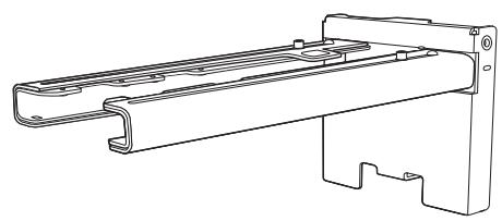
Setting plate
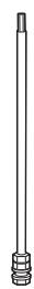
Hexagonal axis

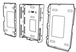
Wall plate
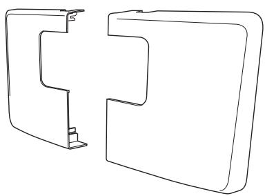
Wall plate cover
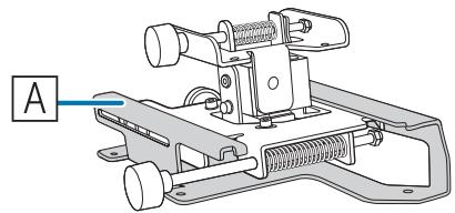
3-axis adjustment unit *The slide plate ( A ) is secured dur- ing shipping.
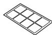
Template sheet (for installing the wall plate)
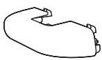
End cap
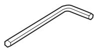
Hexagon wrench (for M4)
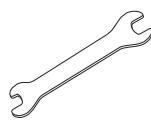
Open-ended spanner 13 mm (for M8 and M6), 6 mm (for hexagonal axis)
| Shape | Name | Quan-tity | Application |
| M4 x 12 mm hexagon socket head cap bolt with washer/spring washer | 6 | For wall plate assembly | |
| 4 | For 3-axis adjustment unit/arm installation | ||
| 4 | For slide plate/projector installation | ||
| 2 | For slide plate/3-axis adjustment unit installa-tion (attached during shipping) | ||
| M6 x 20 mm hexagon shoulder head bolt with washer/spring washer | 1 | For setting plate/wall plate installation | |
| M6 x 20 mm cross recessed head shoulder screws with plastic washers | 3 |
- Use the bolts or screws supplied with this product to install it as directed in this guide. Do not substitute these bolts with any other types.
- You need to use commercially available M10 x 60 mm anchors (at least 3) to attach the wall plate to the wall.
- Gather the tools and parts you need before you begin installation.
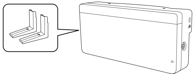
Control Pad
The following supplied products are necessary when attaching the Control Pad. Confirm that you have all items before beginning.
Control Pad main unit
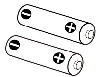
AA size batteries (x2)

Rubber feet
Port protection stickers
When installing the Control Pad on a wall and so on, prepare commercially available M4 screws (20 mm x4).
Touch Unit (EB-1430Wi only)
The following supplied products are necessary when attaching the Touch Unit. Confirm that you have all items before beginning.
Touch Unit/Markers x2 (attached to Touch Unit)
Touch Unit connection cable


Spacer for screw hole x3
Label x4
Tape (approx. 6 cm) for securing the marker x12
Infrared deflector (approx. 28.5cm ) x8
When installing the Touch Unit on a non-magnetic surface, prepare three M4 screws.
Setting plate
| Item | Specification | Remark | Reference Page |
| Setting plate weight | Approx. 8.1 kg | Setting plate (3.0 kg), 3-axis adjustment unit (1.2 kg), slide plate (0.8 kg), wall plate (2.7 kg), wall plate cover and end cap (0.4 kg) | |
| Maximum load capacity | 7 kg | ||
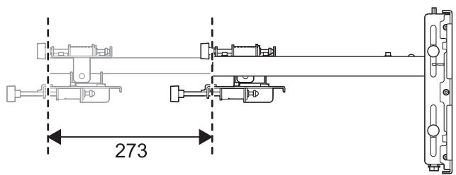
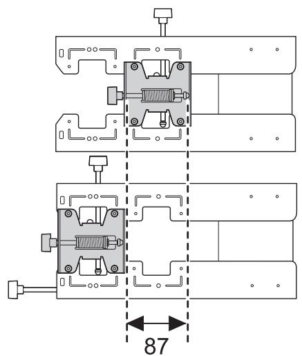
| Forward/backward slide adjustment range | 0 to 360 mm | Arm slide adjustment range: 0 to 273 mmAdjustment for 3-axis adjustment unit installation position: 87 mm | See the figure below |
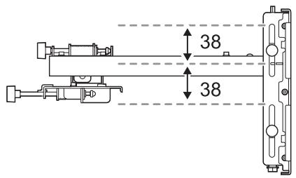
| Vertical slide adjustment range | ±38 mm | See the figure below | |
| Horizontal roll adjustment range | ±3° | Fine adjustments possible with adjustment dial | p.40 |
| Horizontal rotation adjustment range | ±8° | Fine adjustments possible with adjustment dial | p.40 |
| Vertical tilt adjustment range | ±3° | Fine adjustments possible with adjustment dial | p.40 |
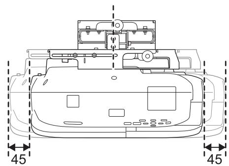
| Horizontal slide adjustment range | ±45 mm | See the figure below |
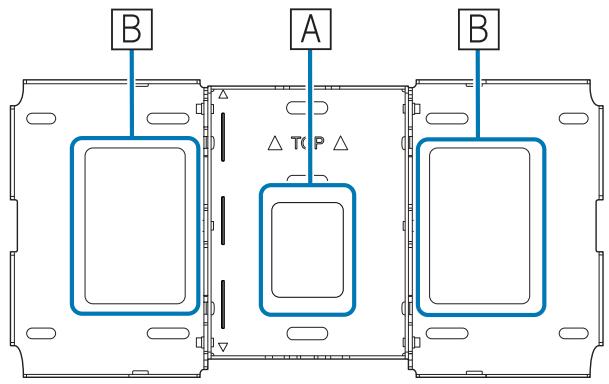
Wall plate
The following figure shows three wall plates connected to form one plate (separate when shipped).
[Unit: mm]
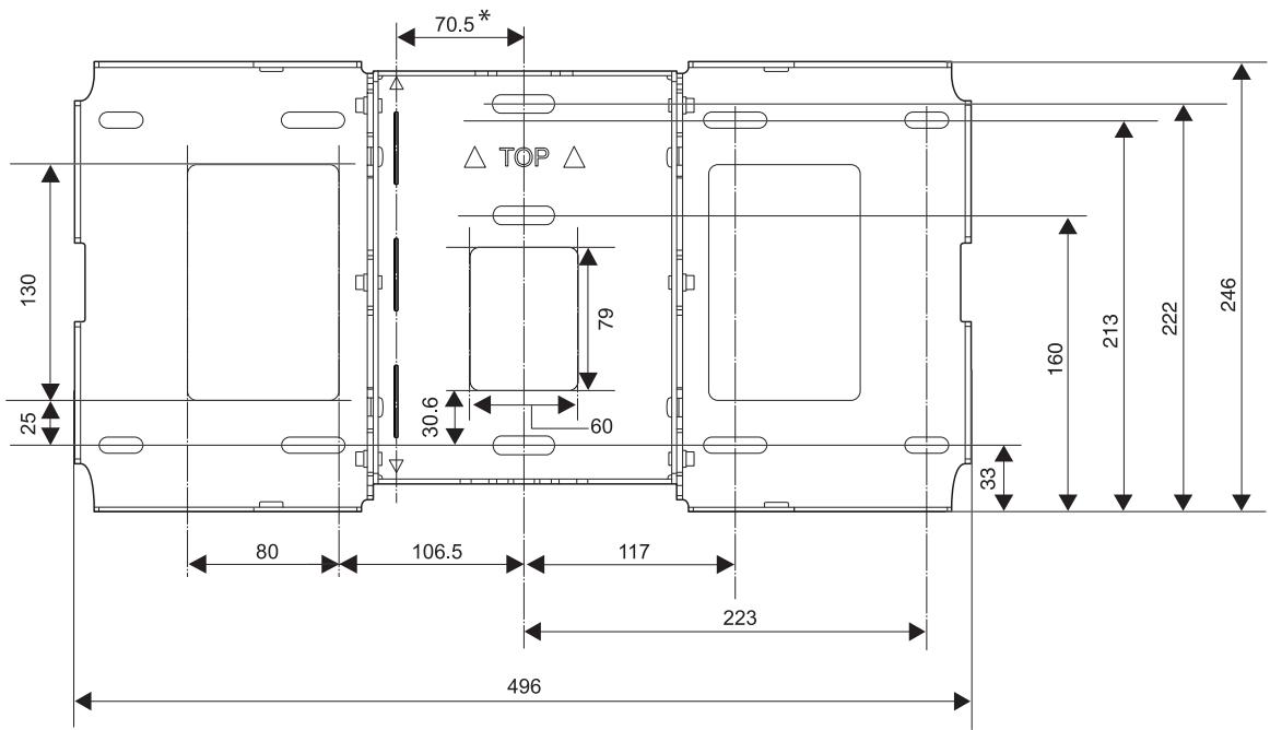
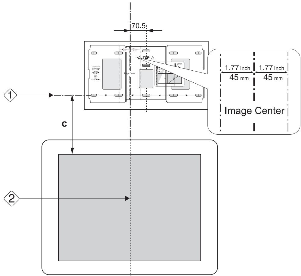
- Offset value for the position of the center of the projected image and the center of the wall plate
Cable routing holes
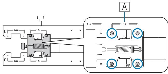
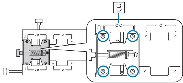
When routing cables to connect to the projector through a wall, use positions (A) and (B) in the following figure as the cable routing holes.
Vertical slide adjustment range
[Unit: mm]
Horizontal slide adjustment range
[Unit: mm]
Forward/backward slide adjustment range
Arm slide adjustment range
[Unit: mm]
Adjustment range for 3-axis adjustment unit installation position
[Unit: mm]
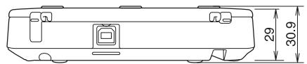
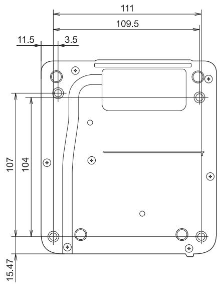
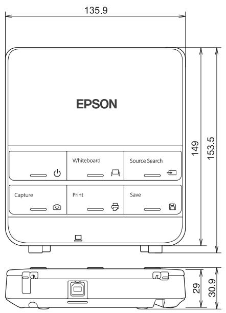
Control Pad
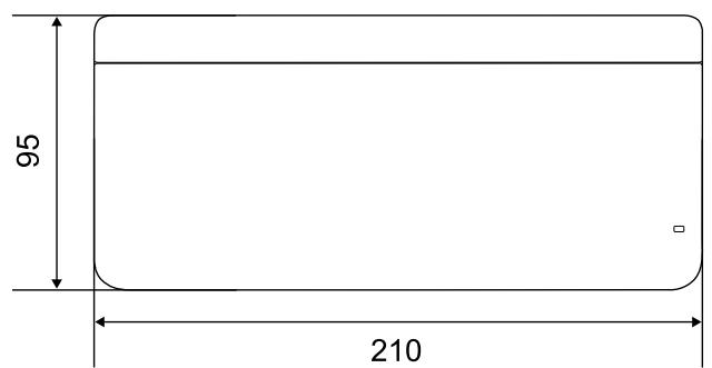
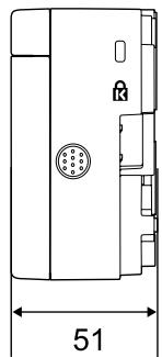
Control Pad (external dimensions/weight)
[Unit: mm]
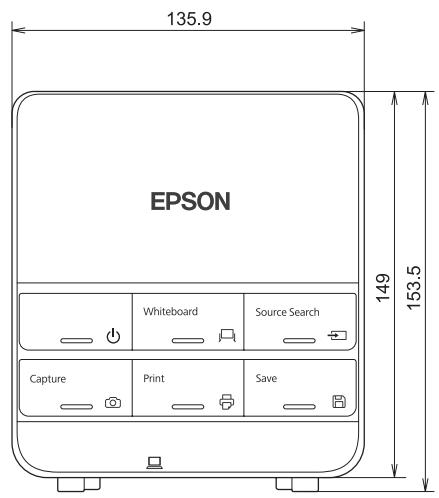
- Weight: approx. 240g (not including batteries and rubber feet)
- Operating temperature: 0 to +50^ (no condensation)
- Operating temperature: -20 to +60^ (no condensation)
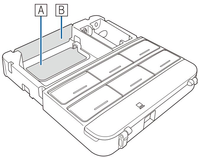
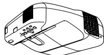
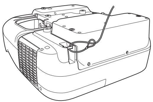
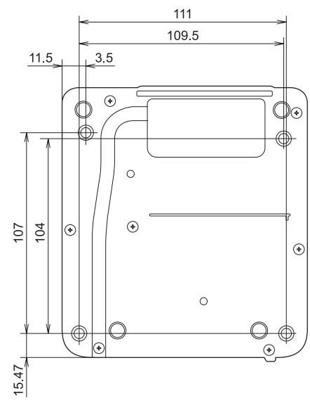
Cable routing holes
When routing cables through a wall, use the position (A) in the following figure as the cable routing hole. Otherwise, remove the cable cover (B) and route the cables from there. Route the printer cable along the groove at the back of the Control Pad.
Touch Unit (EB-1430Wi only)
Touch Unit (external dimensions/weight)
[Unit: mm]
The Touch Unit weighs 450 g.
Attached labels
The Touch Unit is a Class 1 laser product that conforms to the JIS C 6802:2011 standard. There are warning labels affixed to the Touch Unit to indicate that it is a Class 1 laser product.
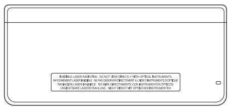
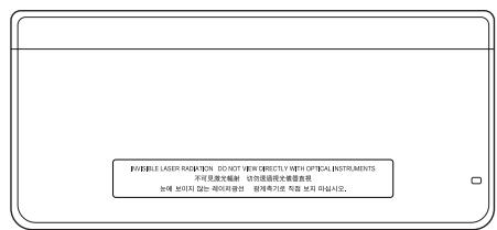
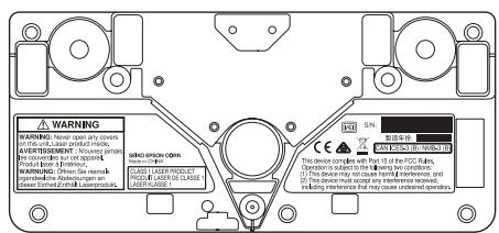
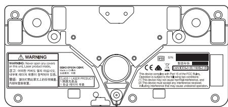
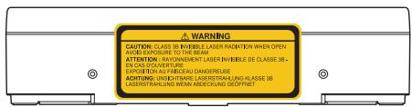
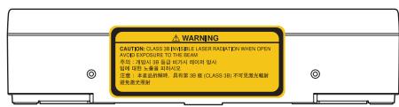
The labels contain the following information.
CLASS 1 LASER PRODUCT
- WARNING: Never open any covers on this unit. Laser product inside.
- Warning:
- CAUTION: CLASS 3B INVISIBLE LASER RADIATION WHEN OPEN.
- AVOID EXPOSURE TO THE BEAM
The laser beam is diffused from the laser diffusion ports at the back of the Touch Unit.

Projection Distance Table
Figures of Installation Dimensions
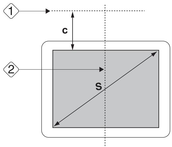
To find the appropriate screen size, see the following figures when installing. The values are only rough estimates.
The recommended range for the projection distance (a) is 62 to 311~mm .
The offset value for the position of the center of the projected image and the center of the wall plate is 70.5 mm.
When the projected image size (S) is 75 inches or more, the scale on the arm slide (b) is equal to the projection distance (a).
The numbers for (a) and (b) differ if the projected image size (S) is less than 75 inches.
[Unit: mm]
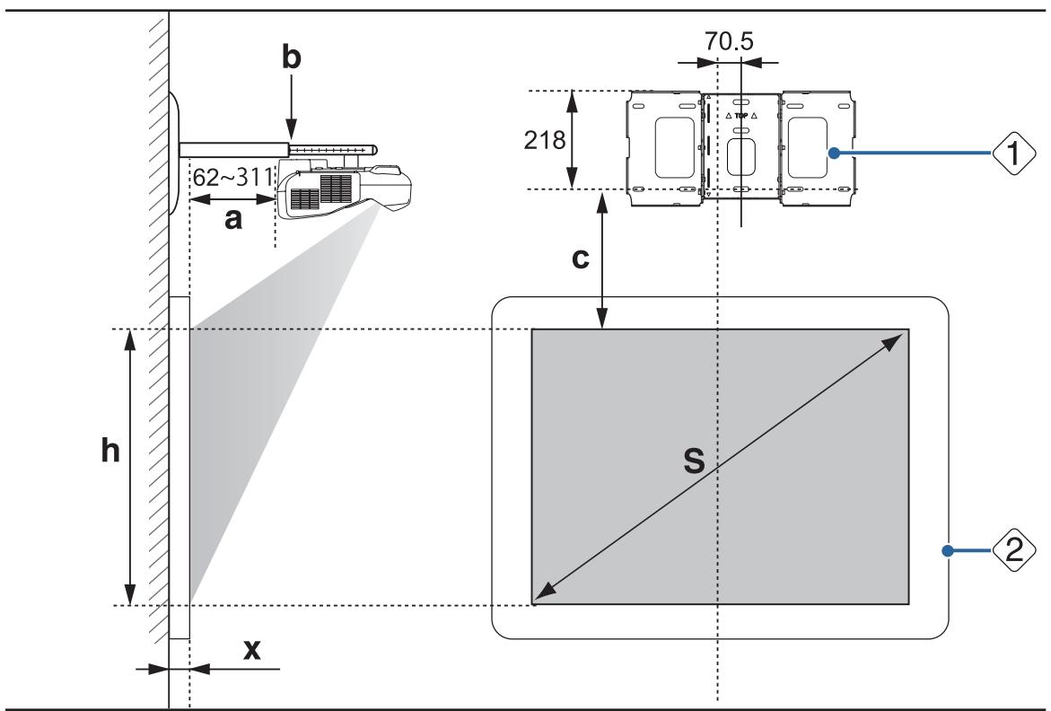
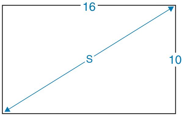
S : Projected image size
1: Wall plate
a : Minimum projection distance (Wide: maximum zoom) to maximum (Tele: minimum zoom)
2:Screen
b : Numbers on the arm slide scale
c : Distance from projected image to wall plate
h : Height of projected image
X : Distance from surface of screen to wall (100 mm or less)

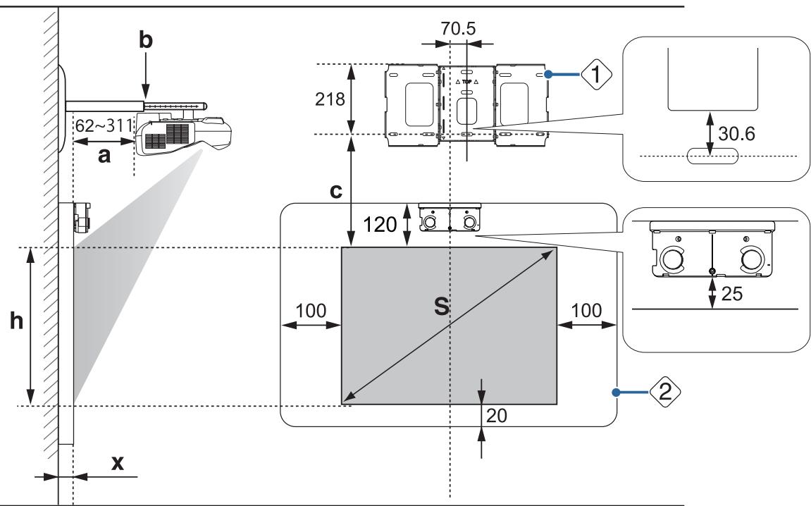
When installing the Touch Unit (EB-1430Wi only)
When installing the Touch Unit, install it on the screen that is being used for projection.
You need at least 120mm distance between the top edge of the projected image and the top edge of the actual screen to install the Touch Unit.

Caution
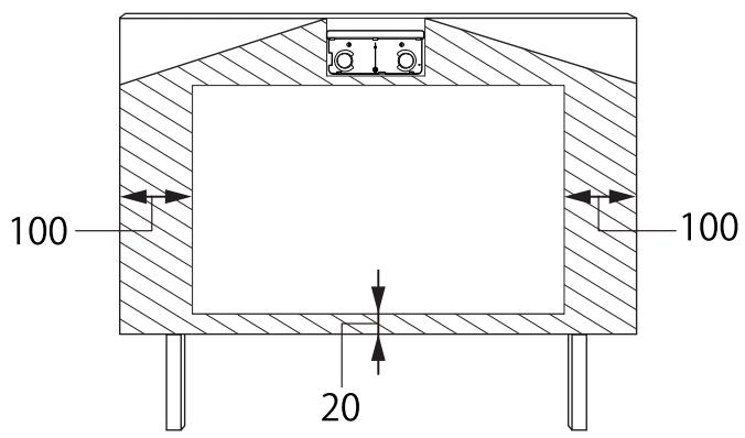
Leave the following gaps around the edge of the screen.
- From the top of the projected image to the bottom of the Touch Unit: 25 mm
- From the edges of the projected image to the edges of the screen: At least 100mm left and right
- From the bottom of the projected image to the bottom of the screen: At least 20mm
If there are obstacles such as cables, whiteboard trays, holders, or frames within the areas noted above, the Touch Unit will not operate correctly.
[Unit: mm]
S : Projected image size
1: Wall plate
a : Minimum projection distance (Wide: maximum zoom) to maximum (Tele: minimum zoom)
2:Screen
b : Numbers on the arm slide scale
c : Distance from projected image to wall plate
h : Height of projected image
X : Distance from surface of screen to wall (100 mm or less)
Aspect ratio for standard projected image
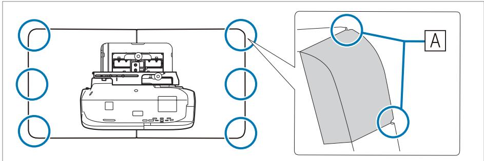
When installing the Control Pad
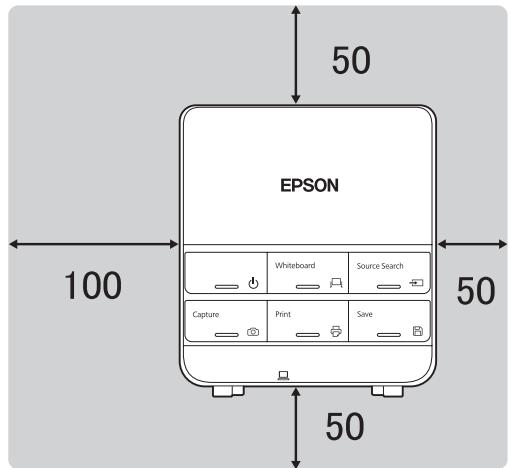
When installing the Control Pad, make sure there is enough space in the surrounding area as shown in the following figure. Because the top cover opens from the left-hand side, you need space on the left-hand side of the Control Pad.
[Unit: mm]
When supplying power using batteries, install the Control Pad within the shaded range shown in the following figure.
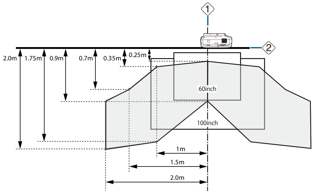
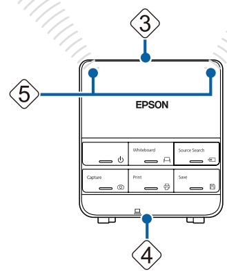
1: Center of screen
2: Top of projector
3:Top of Control Pad
4: Bottom of Control Pad
5: Remote control light-emitting area
Align the top of the projector with the top of the Control Pad, and point the Control Pad's remote control light-emitting area at the projector.

When installing the Touch Unit, do not install the Control Pad on the projection screen and the surrounding area (shaded area in the following figure) (EB-1430Wi only). The Touch Unit will not operate correctly.
[Unit: mm]
When Projected Image is Smaller than 75 Inches
Mount the 3-axis adjustment unit at the position marked with a stamp (A).
The projection distance table provides the figures when mounting the 3-axis adjustment unit at the position marked with a stamp (A). The numbers on the arm slide scale (b) differ from the projection distance (a).
The distance (c) from the projected image to the wall plate is the number given when the vertical slide is set to the standard position (B).
Match the notch on the setting plate to the position of the stamp on the wall plate.
16:10 projected image
[Unit: cm]
| S Projected image size | a Projection Dis-tance Minimum (Wide) to Maximum (Tele) | b Numbers on the arm slide scale | c Distance from projected image to wall plate | h Height of projec- ted image | |
| 60" | 129.2x80.8 | 6.2 - 19.3 | 14.9 - 28.0 | 17.4 | 80.8 |
| 61" | 131.4x82.1 | 6.9 - 20.1 | 15.6 - 28.8 | 17.7 | 82.1 |
| 62" | 133.5x83.5 | 7.5 - 20.9 | 16.2 - 29.6 | 17.9 | 83.5 |
| 63" | 135.7x84.8 | 8.1 - 21.8 | 16.8 - 30.5 | 18.2 | 84.8 |
| 64" | 137.9x86.2 | 8.7 - 22.6 | 17.4 - 31.3 | 18.5 | 86.2 |
| 65" | 140.0x87.5 | 9.3 - 23.5 | 18.0 - 32.2 | 18.7 | 87.5 |
| 66" | 142.2x88.8 | 10.0 - 24.3 | 18.7 - 33.0 | 19.0 | 88.8 |
| 67" | 144.3x90.2 | 10.6 - 25.1 | 19.3 - 33.8 | 19.3 | 90.2 |
| 68" | 146.5x91.5 | 11.2 - 26.0 | 19.9 - 34.7 | 19.5 | 91.5 |
| 69" | 148.6x92.9 | 11.8 - 26.8 | 20.5 - 35.5 | 19.8 | 92.9 |
| 70" | 150.8x94.2 | 12.4 - 27.6 | 21.1 - 36.3 | 20.1 | 94.2 |
| 71" | 152.9x95.6 | 13.1 - 28.5 | 21.8 - 37.2 | 20.3 | 95.6 |
| 72" | 155.1x96.9 | 13.7 - 29.3 | 22.4 - 38.0 | 20.6 | 96.9 |
| 73" | 157.2x98.3 | 14.3 - 30.2 | 23.0 - 38.9 | 20.9 | 98.3 |
| 74" | 159.4x99.6 | 14.9 - 31.0 | 23.6 - 39.7 | 21.1 | 99.6 |
Images smaller than 60 inches are not projected correctly.
16:9 projected image
[Unit: cm]
| S Projected image size | a Projection Dis-tance Minimum (Wide) to Maximum (Tele) | b Numbers on the arm slide scale | c Distance from projected image to wall plate | h Height of projec- ted image | |
| 59" | 130.6x73.5 | 6.6 - 19.8 | 15.3 - 28.5 | 21.7 | 73.5 |
| 60" | 132.8x74.7 | 7.3 - 20.7 | 16.0 - 29.4 | 22.0 | 74.7 |
| 61" | 135.0x76.0 | 7.9 - 21.5 | 16.6 - 30.2 | 22.3 | 76.0 |
| 62" | 137.3x77.2 | 8.6 - 22.4 | 17.3 - 31.1 | 22.7 | 77.2 |
| 63" | 139.5x78.5 | 9.2 - 23.3 | 17.9 - 32.0 | 23.0 | 78.5 |
| 64" | 141.7x79.7 | 9.8 - 24.1 | 18.5 - 32.8 | 23.4 | 79.7 |
| 65" | 143.9x80.9 | 10.5 - 25.0 | 19.2 - 33.7 | 23.7 | 80.9 |
| 66" | 146.1x82.2 | 11.1 - 25.8 | 19.8 - 34.5 | 24.1 | 82.2 |
| 67" | 148.3x83.4 | 11.7 - 26.7 | 20.4 - 35.4 | 24.4 | 83.4 |
| 68" | 150.5x84.7 | 12.4 - 27.6 | 21.1 - 36.3 | 24.8 | 84.7 |
| 69" | 152.8x85.9 | 13.0 - 28.4 | 21.7 - 37.1 | 25.1 | 85.9 |
| 70" | 155.0x87.2 | 13.7 - 29.3 | 22.4 - 38.0 | 25.4 | 87.2 |
| 71" | 157.2x88.4 | 14.3 - 30.1 | 23.0 - 38.8 | 25.8 | 88.4 |
| 72" | 159.4x89.7 | 14.9 - 31.0 | 23.6 - 39.7 | 26.1 | 89.7 |
| 73" | 161.6x90.9 | 15.6 - 31.1 | 24.3 - 39.8 | 26.5 | 90.9 |
| 74" | 163.8x92.1 | 16.2 - 31.1 | 24.9 - 39.8 | 26.8 | 92.1 |
Images smaller than 59 inches are not projected correctly.
4:3 projected image
[Unit: cm]
| S Projected image size | a Projection Dis-tance Minimum (Wide) to Maximum (Tele) | b Numbers on the arm slide scale | c Distance from projected image to wall plate | h Height of projec- ted image | |
| 53" | 107.7x80.8 | 6.2 - 19.3 | 14.9 - 28.0 | 17.4 | 80.8 |
| 54" | 109.7x82.3 | 6.9 - 20.2 | 15.6 - 28.9 | 17.7 | 82.3 |
| 55" | 111.8x83.8 | 7.6 - 21.2 | 16.3 - 29.9 | 18.0 | 83.8 |
| 56" | 113.8x85.3 | 8.3 - 22.1 | 17.0 - 30.8 | 18.3 | 85.3 |
| 57" | 115.8x86.9 | 9.1 - 23.1 | 17.8 - 31.8 | 18.6 | 86.9 |
| 58" | 117.9x88.4 | 9.8 - 24.0 | 18.5 - 32.7 | 18.9 | 88.4 |
| 59" | 119.9x89.9 | 10.5 - 25.0 | 19.2 - 33.7 | 19.2 | 89.9 |
| 60" | 121.9x91.4 | 11.2 - 25.9 | 19.9 - 34.6 | 19.5 | 91.4 |
| 61" | 124.0x93.0 | 11.9 - 26.9 | 20.6 - 35.6 | 19.8 | 93.0 |
| 62" | 126.0x94.5 | 12.6 - 27.8 | 21.3 - 36.5 | 20.1 | 94.5 |
| 63" | 128.0x96.0 | 13.3 - 28.8 | 22.0 - 37.5 | 20.4 | 96.0 |
| 64" | 130.0x97.5 | 14.0 - 29.7 | 22.7 - 38.4 | 20.7 | 97.5 |
| 65" | 132.1x99.1 | 14.7 - 30.7 | 23.4 - 39.4 | 21.0 | 99.1 |
| 66" | 134.1x100.6 | 15.4 - 31.1 | 24.1 - 39.8 | 21.3 | 100.6 |
| 67" | 136.1x102.1 | 16.1 - 31.1 | 24.8 - 39.8 | 21.6 | 102.1 |
| 68" | 138.2x103.6 | 16.8 - 31.1 | 25.5 - 39.8 | 21.9 | 103.6 |
| 69" | 140.2x105.2 | 17.5 - 31.1 | 26.2 - 39.8 | 22.2 | 105.2 |
| 70" | 142.2x106.7 | 18.2 - 31.1 | 26.9 - 39.8 | 22.5 | 106.7 |
| 71" | 144.3x108.2 | 18.9 - 31.1 | 27.6 - 39.8 | 22.8 | 108.2 |
| 72" | 146.3x109.7 | 19.6 - 31.1 | 28.3 - 39.8 | 23.2 | 109.7 |
| 73" | 148.3x111.3 | 20.3 - 31.1 | 29.0 - 39.8 | 23.5 | 111.3 |
| 74" | 150.4x112.8 | 21.0 - 31.1 | 29.7 - 39.8 | 23.8 | 112.8 |
Images smaller than 53 inches are not projected correctly.

- The values are only rough estimates. The value may differ depending on the location where you place the projector.
- When projecting in Tele, the quality of the projected images may decrease.
- When projecting images at 4:3, the images are resized automatically and the quality of the projected images may decrease.
When Projected Image is Larger than 75 Inches
Mount the 3-axis adjustment unit at the position marked with a stamp (A).
The projection distance table provides the figures when mounting the 3-axis adjustment unit at the position marked with a stamp (A). The numbers on the arm slide scale (b) is the same as the projection distance (a).
The distance (c) from the projected image to the wall plate is the number given when the vertical slide is set to the standard position (B).
Match the notch on the setting plate to the position of the stamp on the wall plate.

16:10 projected image
[Unit: cm]
| S Projected image size | a Projection Dis-tance Minimum (Wide) to Maximum (Tele) | b Numbers on the arm slide scale | c Distance from projected image to wall plate | h Height of projec- ted image | |
| 75" | 161.5x101.0 | 15.5 - 31.1 | 21.4 | 101.0 | |
| 76" | 163.7x102.3 | 16.2 - 31.1 | 21.7 | 102.3 | |
| 77" | 165.9x103.7 | 16.8 - 31.1 | 21.9 | 103.7 | |
| 78" | 168.0x105.0 | 17.4 - 31.1 | 22.2 | 105.0 | |
| 79" | 170.2x106.3 | 18.0 - 31.1 | 22.5 | 106.3 | |
| 80" | 172.3x107.7 | 18.7 - 31.1 | 22.7 | 107.7 | |
| 81" | 174.5x109.0 | 19.3 - 31.1 | 23.0 | 109.0 | |
| 82" | 176.6x110.4 | 19.9 - 31.1 | 23.3 | 110.4 | |
| 83" | 178.8x111.7 | 20.5 - 31.1 | 23.5 | 111.7 | |
| 84" | 180.9x113.1 | 21.1 - 31.1 | 23.8 | 113.1 | |
| 85" | 183.1x114.4 | 21.8 - 31.1 | 24.1 | 114.4 | |
| 86" | 185.2x115.8 | 22.4 - 31.1 | 24.3 | 115.8 | |
| 87" | 187.4x117.1 | 23.0 - 31.1 | 24.6 | 117.1 | |
| 88" | 189.5x118.5 | 23.6 - 31.1 | 24.9 | 118.5 | |
| 89" | 191.7x119.8 | 24.2 - 31.1 | 25.2 | 119.8 | |
| 90" | 193.9x121.2 | 24.9 - 31.1 | 25.4 | 121.2 | |
| 91" | 196.0x122.5 | 25.5 - 31.1 | 25.7 | 122.5 | |
| 92" | 198.2x123.9 | 26.1 - 31.1 | 26.0 | 123.9 | |
| 93" | 200.3x125.2 | 26.7 - 31.1 | 26.2 | 125.2 | |
| 94" | 202.5x126.5 | 27.3 - 31.1 | 26.5 | 126.5 | |
| 95" | 204.6x127.9 | 28.0 - 31.1 | 26.8 | 127.9 | |
| 96" | 206.8x129.2 | 28.6 - 31.1 | 27.0 | 129.2 | |
| 97" | 208.9x130.6 | 29.2 - 31.1 | 27.3 | 130.6 | |
| 98" | 211.1x131.9 | 29.8 - 31.1 | 27.6 | 131.9 | |
| 99" | 213.2x133.3 | 30.4 - 31.1 | 27.8 | 133.3 | |
| 100" | 215.4x134.6 | 31.1* | 28.1 | 134.6 | |
- Figure for Wide (maximum zoom).
Images larger than 100 inches are not projected correctly.
16:9 projected image
[Unit: cm]
| S Projected image size | a Projection Dis-tance Minimum (Wide) to Maximum (Tele) | b Numbers on the arm slide scale | c Distance from projected image to wall plate | h Height of projec- ted image | |
| 75" | 166.0x93.4 | 16.8 - 31.1 | 27.2 | 93.4 | |
| 76" | 168.2x94.6 | 17.5 - 31.1 | 27.5 | 94.6 | |
| 77" | 170.5x95.9 | 18.1 - 31.1 | 27.8 | 95.9 | |
| 78" | 172.7x97.1 | 18.8 - 31.1 | 28.2 | 97.1 | |
| 79" | 174.9x98.4 | 19.4 - 31.1 | 28.5 | 98.4 | |
| 80" | 177.1x99.6 | 20.0 - 31.1 | 28.9 | 99.6 | |
| 81" | 179.3x100.9 | 20.7 - 31.1 | 29.2 | 100.9 | |
| 82" | 181.5x102.1 | 21.3 - 31.1 | 29.6 | 102.1 | |
| 83" | 183.7x103.4 | 21.9 - 31.1 | 29.9 | 103.4 | |
| 84" | 186.0x104.6 | 22.6 - 31.1 | 30.3 | 104.6 | |
| 85" | 188.2x105.8 | 23.2 - 31.1 | 30.6 | 105.8 | |
| 86" | 190.4x107.1 | 23.9 - 31.1 | 30.9 | 107.1 | |
| 87" | 192.6x108.3 | 24.5 - 31.1 | 31.3 | 108.3 | |
| 88" | 194.8x109.6 | 25.1 - 31.1 | 31.6 | 109.6 | |
| 89" | 197.0x110.8 | 25.8 - 31.1 | 32.0 | 110.8 | |
| 90" | 199.2x112.1 | 26.4 - 31.1 | 32.3 | 112.1 | |
| 91" | 201.5x113.3 | 27.0 - 31.1 | 32.7 | 113.3 | |
| 92" | 203.7x114.6 | 27.7 - 31.1 | 33.0 | 114.6 | |
| 93" | 205.9x115.8 | 28.3 - 31.1 | 33.3 | 115.8 | |
| 94" | 208.1x117.1 | 29.0 - 31.1 | 33.7 | 117.1 | |
| 95" | 210.3x118.3 | 29.6 - 31.1 | 34.0 | 118.3 | |
| 96" | 212.5x119.5 | 30.2 - 31.1 | 34.4 | 119.5 | |
| 97" | 214.7x120.8 | 30.9 - 31.1 | 34.7 | 120.8 | |
Images larger than 97 inches are not projected correctly.
4:3 projected image
[Unit: cm]
| S Projected image size | a Projection Distance Minimum (Wide) to Maximum (Tele) | b Numbers on the arm slide scale | c Distance from projected image to wall plate | h Height of projected image | |
| 75" | 152.4x114.3 | 21.7 - 31.1 | 24.1 | 114.3 | |
| 76" | 154.4x115.8 | 22.4 - 31.1 | 24.4 | 115.8 | |
| 77" | 156.5x117.3 | 23.1 - 31.1 | 24.7 | 117.3 | |
| 78" | 158.5x118.9 | 23.8 - 31.1 | 25.0 | 118.9 | |
| 79" | 160.5x120.4 | 24.5 - 31.1 | 25.3 | 120.4 | |
| 80" | 162.6x121.9 | 25.2 - 31.1 | 25.6 | 121.9 | |
| 81" | 164.6x123.4 | 25.9 - 31.1 | 25.9 | 123.4 | |
| 82" | 166.6x125.0 | 26.6 - 31.1 | 26.2 | 125.0 | |
| 83" | 168.7x126.5 | 27.3 - 31.1 | 26.5 | 126.5 | |
| 84" | 170.7x128.0 | 28.0 - 31.1 | 26.8 | 128.0 | |
| 85" | 172.7x129.5 | 28.7 - 31.1 | 27.1 | 129.5 | |
| 86" | 174.8x131.1 | 29.4 - 31.1 | 27.4 | 131.1 | |
| 87" | 176.8x132.6 | 30.1 - 31.1 | 27.7 | 132.6 | |
| 88" | 178.8x134.1 | 30.8 - 31.1 | 28.0 | 134.1 | |
Images larger than 88 inches are not projected correctly.

- The values are only rough estimates. The value may differ depending on the location where you place the projector.
- When projecting in Tele, the quality of the projected images may decrease.
- When projecting images at 4:3, the images are resized automatically and the quality of the projected images may decrease.

Installing the Setting Plate
Connecting Devices
Necessary cables
Prepare the necessary cables according to the devices being used.
- Power cord supplied (necessary)
- USB cable supplied
- Touch Unit connection cable supplied (EB-1430Wi only)
- Optional computer cables, Remote control cable set, and other cables (prepare according to the connected devices)
For details, see the projector's User's Guide (on the Document CD-ROM).
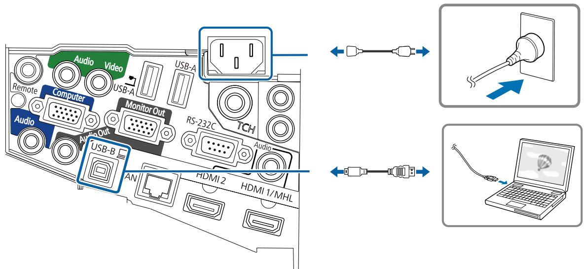
Necessary cables when using the Easy Interactive Function
When performing mouse operations using the Easy Interactive Function, you need a power cord and USB cable. Even when projecting using a computer cable, a USB cable is necessary to perform mouse operations.
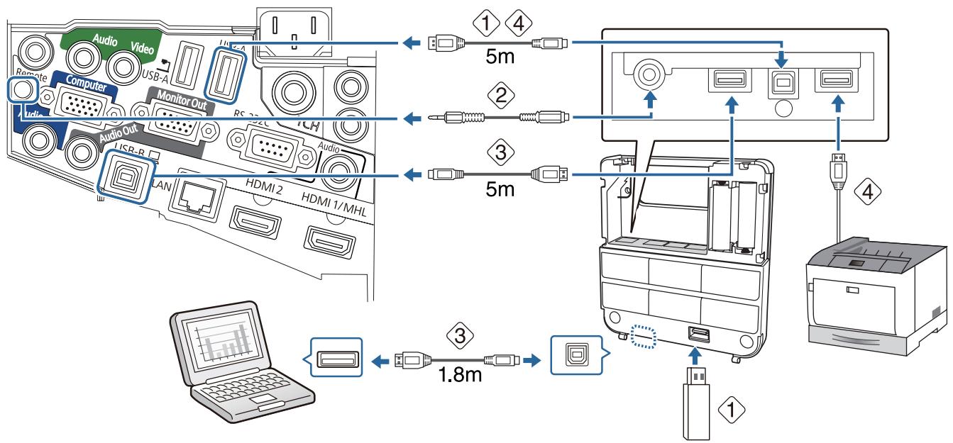
Necessary cables when installing the Control Pad
- When projecting images from a USB storage device, or when saving data to the USB storage device, you need the USB cable supplied (1).
- When supplying power from the projector, you need the optional Remote control cable set (ELPKC28) (2).
- When projecting computer images (USB Display), or performing mouse operations using the Easy Interactive Function, you need the USB cable supplied ( 3 ).
- When printing the projected image, you need the USB cable supplied. To connect the Control Pad and the printer, use the USB cable supplied with the printer (4).

The following Epson projectors can be connected to the Control Pad. Check the rating label on the projector.
- H480x (where x is one letter from A to Z)
- H481x (where x is one letter from A to Z)
- H612x (where x is one letter from A to Z)
- H665x (where x is one letter from A to Z)
This information is current as of May 30th, 2014. If you want to connect a different projector or if you have any queries, contact your local dealer from the Epson Projector Contact List provided on the Document CD-ROM.
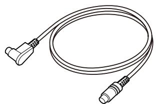
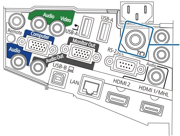
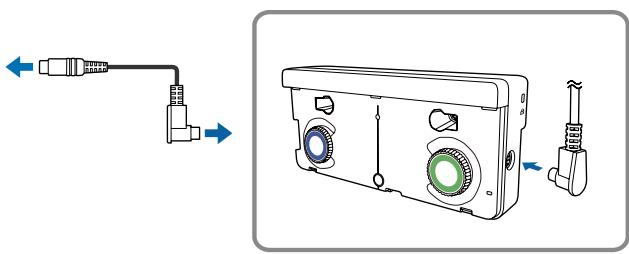
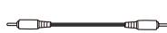
Necessary cables when installing the Touch Unit (EB-1430Wi only)
You need the supplied Touch Unit connection cable when installing the Touch Unit and connecting it to the projector. Operations are not performed correctly with a commercially available cable.
The shape of the plug that connects to the projector and the plug that connects to the Touch Unit differ. See the following figure to connect to the correct ports.
Prepare cables for the connected devices (example)
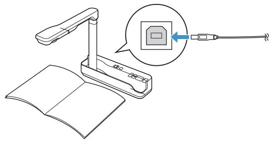
Document camera
Dedicated USB cable (supplied with document camera)
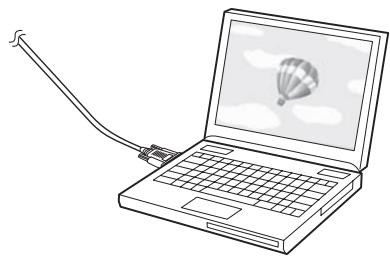
Computer
Computer cable (optional accessory)
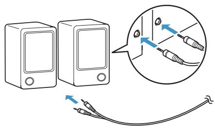
External speakers
Audio cable (commercially available)
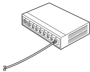
LAN device
LAN cable (commercially available)
Installation Procedure
Make sure to follow the steps below to install the setting plate. If these steps are not followed, the product could fall and cause personal injury or property damage.

Warning
Do not use adhesives, lubricants, or oils to install or adjust the setting plate. If you use adhesives to prevent the screws from loosening or things such as lubricants or oils on the slide plate fixing part of the projector, the case may crack and cause the projector to fall, resulting in personal injury or property damage.

Disassemble the parts
Remove the M4 bolts (x2), and then remove the slide plate from the 3-axis adjustment unit.
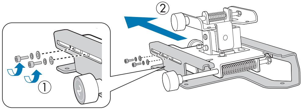

Assemble the parts
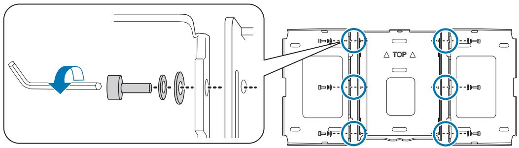
1 Assembled supplied
Assemble the three wall plates into one unit, and secure them with the M4 bolts (x6) supplied
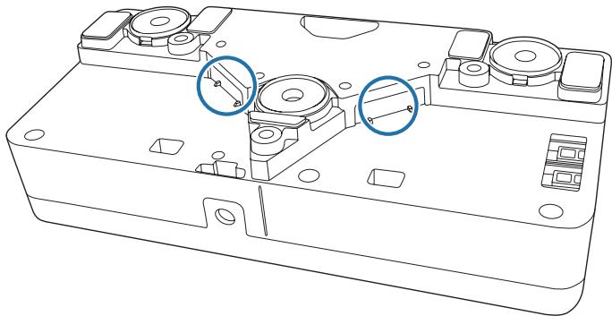
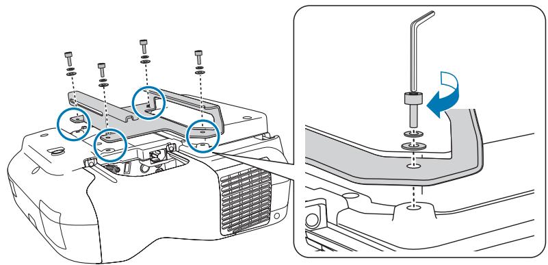
2
Secure the slide plate to the base of the projector with the M4 bolts (x4) supplied
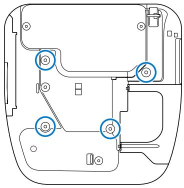
Bolt installation positions
3
Attach the 3-axis adjustment unit to the setting plate with the M4 bolts (x4) supplied
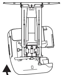
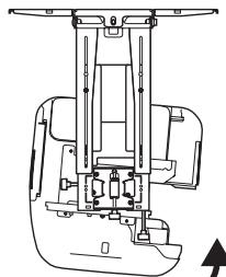
- When a projected image is smaller than 75 inches: Mount the unit at the stamp (A).
- When a projected image is larger than 75 inches: Mount the unit at the stamp (B).
: Smaller than 75 inches
: Larger than 75 inches

Determine the projection position based on the projected image size
See the projection distance table to calculate the projected image size (S) and the distance (c) from the projected image to the wall plate.
"Projection Distance Table" p.17
We recommend marking the following positions. These will be the basis for determining the mounting position of the wall plate.
- Height (1) of the distance (c) between the top edge of the projected image and the wall plate
Center line (2) of the projected image
2
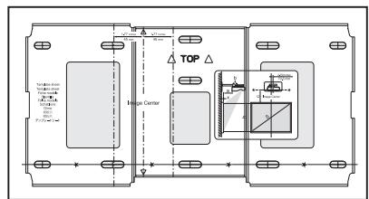
Attach the template sheet to the wall
- Match the center line ( 2 ) checked in step 1 to the Image Center line on the template sheet. Confirm where the beams are within the wall, and shift the position left or right as necessary. (The position can be shifted horizontally left or right from the center line of the projection surface up to a maximum of 45 mm.)
- Match the height (1) checked in step 1 to the ★ line on the template sheet.
[Unit: mm]
3
Determine the positions for the mounting holes for the wall plate
Secure the wall plate in at least three points.
- If securing the wall plate in four places, make the holes indicated by A or B in the figure.
- If securing the wall plate in three places, make the holes indicated by C in the figure.
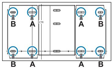
Four mounting holes
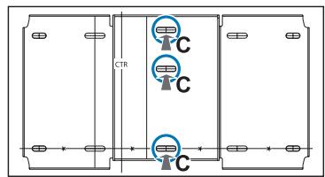
Three mounting holes

Drill the holes in the wall
Drill diameter: 10.5mm
Pilot hole depth: 45 mm
Anchor hole depth: 40mm
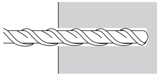

Remove the template sheet, and clean the concrete dust from the holes with a dust pump
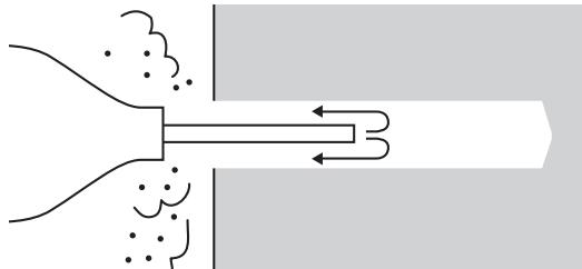

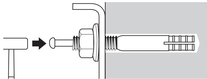
Position the wall plate on the wall and insert M10 x 60 mm commercially available anchors into the holes
Attach the nut and tap it with a hammer until the core touches the top of the anchor.

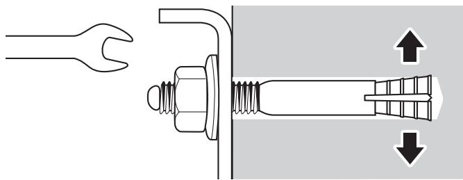
Tighten the nut with a commercially available spanner to secure the wall plate to the wall

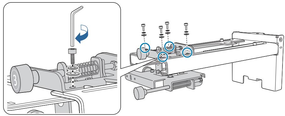
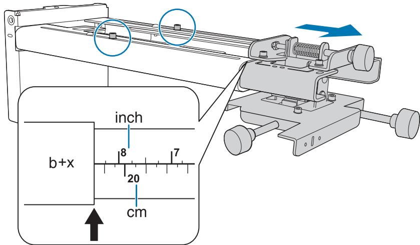
Determine the projection distance, and then pass the cables through the setting plate

Check the following values in the projection distance table
- Numbers on the arm slide scale (b)
- Distance from surface of screen to wall (x)
"Projection Distance Table" p.17
2
Loosen the M4 bolts (x2) and extend the arm slide on the setting plate
Align the slider with the combined distances of (b) and (x) that you checked in step 1.
3
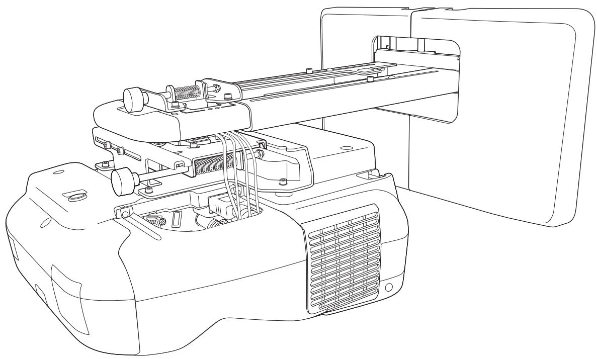
Route the necessary cables through the setting plate
See the following figure to route the cables so that the ends of the cables that connect to the projector are on the projector's interface side.
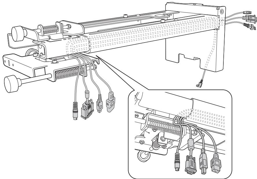

Warning
Do not hang the rest of the cable over the setting plate. They could fall and cause an accident.

- Route the cables connected to the Control Pad through the setting plate.
- Route the cables connected to the Touch Unit through the setting plate (EB-1430Wi only). Route the cable so that the end that connects to the Touch Unit appears from the lower part of the setting plate.
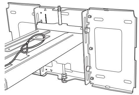
1 Insert the hexagonal axis into the setting plate
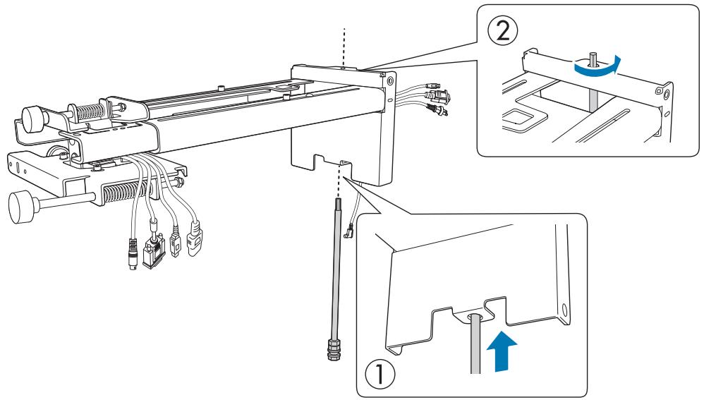
Mount the setting plate to the wall plate
Insert the top of the hexagonal axis into the wall plate, and then insert the M8 bolt into the slot at the bottom.

Caution
- Do not wire the Touch Unit connection cable into the wall (EB-1430Wi only). If it is wired into the wall, it cannot be connected to the Touch Unit.
- Take care not to trap the cables between the setting plate and wall plate.
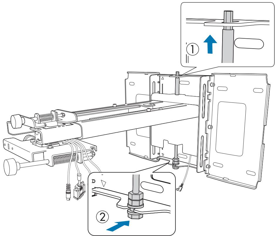
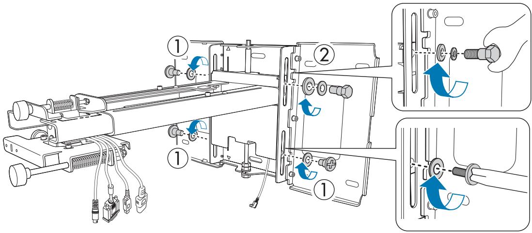
3
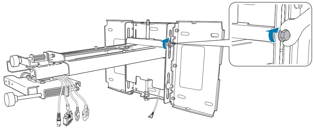
Secure the setting plate and the wall plate
Secure the supplied M6 screws (x3) with a commercially available No.3 cross-head screwdriver, and then lightly tighten the supplied M6 bolt (x1) with the spanner.
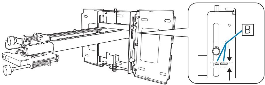
4
Adjust the vertical slide with the open-ended spanner, and align it with the standard position (C)
- Tightening the hexagonal axis at the top (A) raises the setting plate, and loosening the axis lowers it.
- Tightening the M8 bolt at the bottom (B) lowers the setting plate, and loosening the bolt raises it.
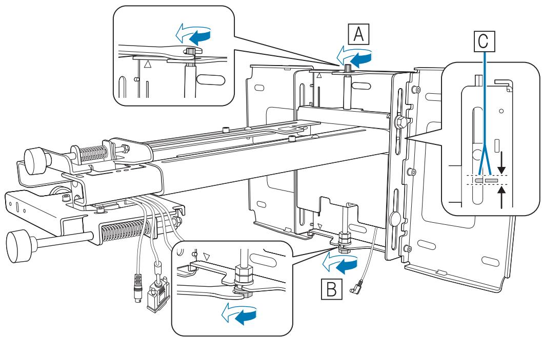
5 Tighten the Mo bolt (X1) to fix the setting plate in position
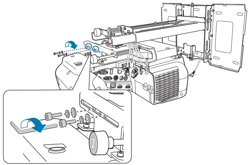
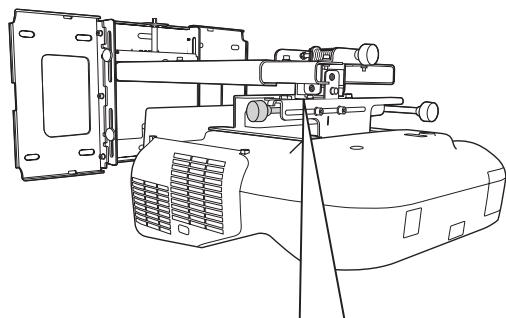
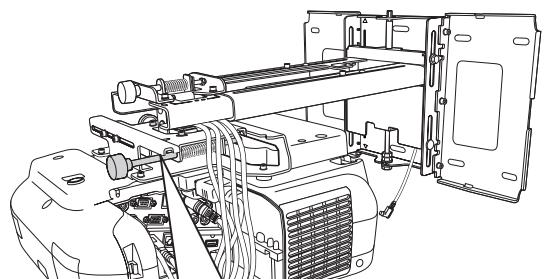
Securing the projector to the setting plate
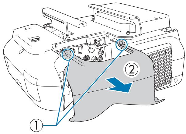
1 Loosen the screws (x2) and remove the cable cover from the projector
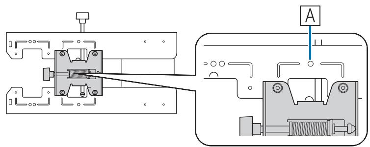
2 insert the slide plate into the setting plate from the interface side of the projector
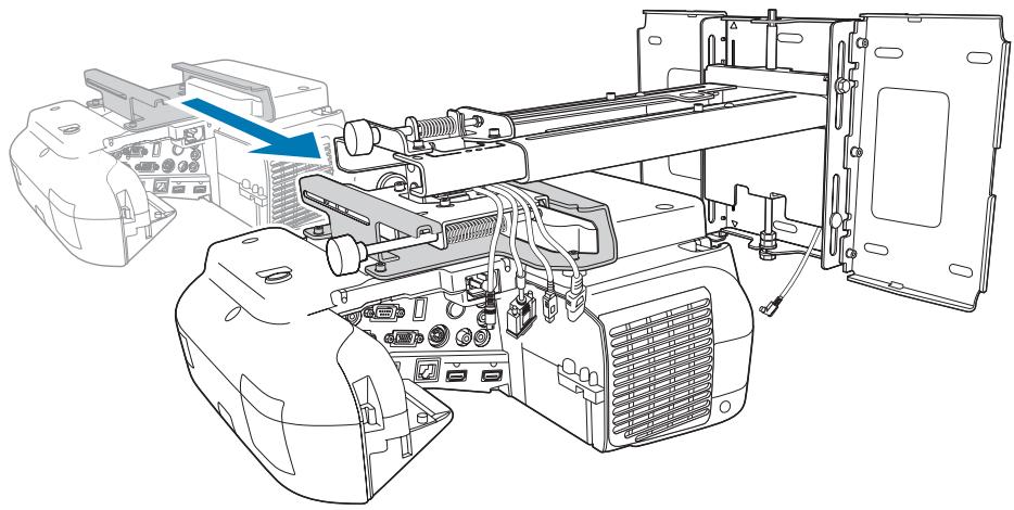
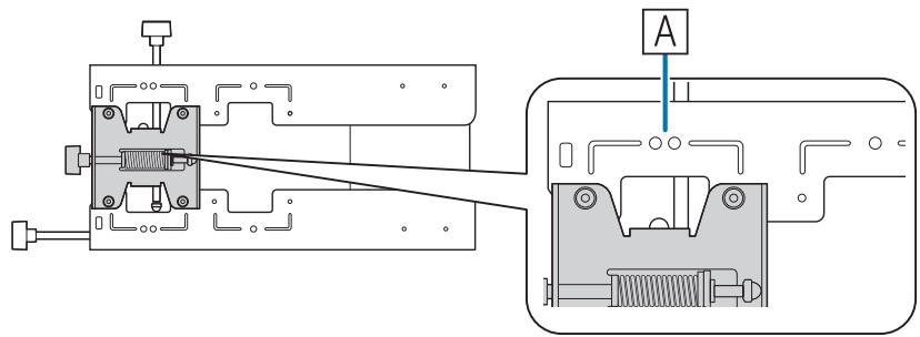
3
Align the 3-axis adjustment unit with the slide plate's standard position (A)
(B) indicates the screw holes for the bolts.
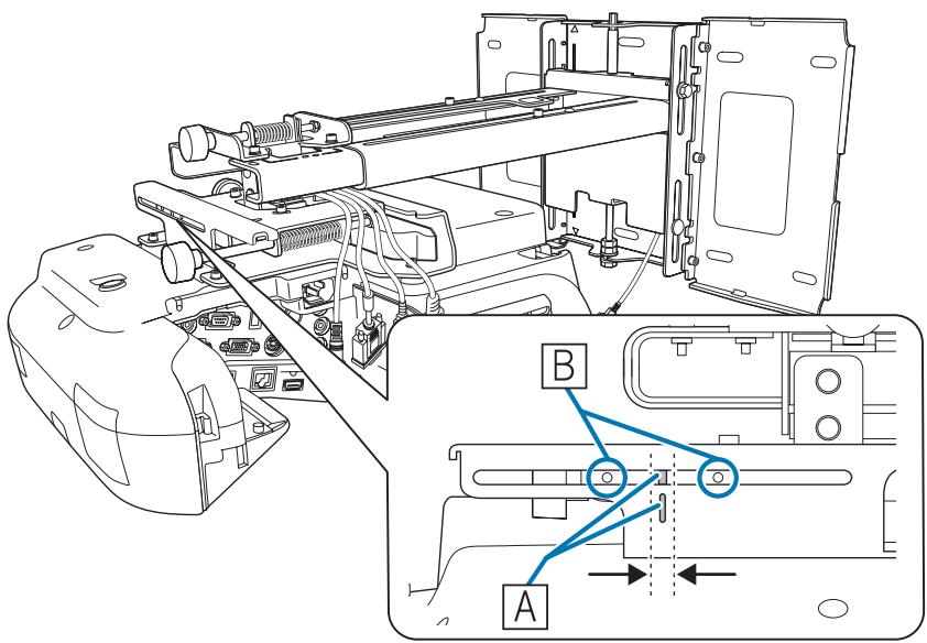
4
Tighten the supplied M4 bolts (x2)
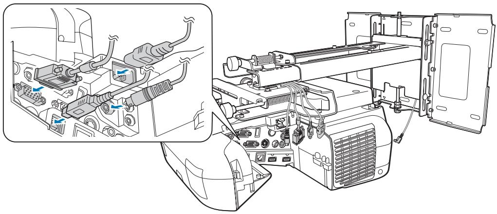
Connect the cables to the projector
5
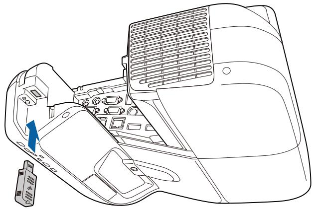
Attach the Wireless LAN unit supplied to the wireless LAN unit's installation section.

- Connect the power cord last.
- When connecting to the Audio1, Audio Out, and Computer ports, we recommend connecting cables to the ports in the following order: Audio1, Audio Out, and then Computer.
Adjusting the Projected Image
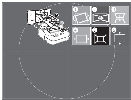
Follow the procedures below to adjust the projected image.
1 Adjusting the Projection Position (p.40)
2 Fine-tuning the Focus (p.46)
3 Calibrating the Pen (p.47)
Adjusting the Projection Position
- Do not make adjustments using the projector's Keystone function. Doing so may result in a reduction in image quality.
- When setting up multiple projectors using the batch setup function, perform this procedure before adjusting the projected image.
"Batch Setup Function" p.75
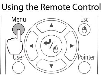
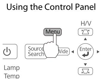
1
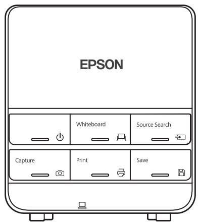
Press the O button on the remote control or the control panel to turn on the projector
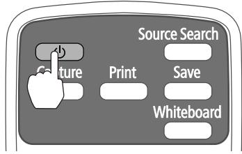
Using the Remote Control
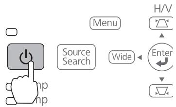
Using the Control Panel

Caution
While projecting, do not put your face or hands near the air exhaust vent, and do not place objects that may become warped or damaged by heat near the vent. Hot air from the air exhaust vent could cause burns, warping, or accidents to occur.
2
Change the aspect ratio of the projected image (only when necessary)
Project images from a connected device, and then press the [Aspect] button on the remote control.
Each time you press the button, the aspect name is displayed on the screen and the aspect ratio changes.
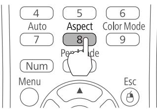
Using the Remote Control


- For details on connecting to devices and projecting images, see the Quick Start Guide.
- The aspect ratio does not change when no images are being projected from the connected device.
- You can also change the aspect ratio from Signal - Aspect from the Configuration menu.
Projector's User's Guide - Configuration menu

Press the following buttons to display the guidance screen
Using the Remote Control
Press the [Help], and then press [] .
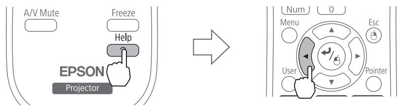
- Using the Control Panel
Press the [Help], and then press the [Wide] button.
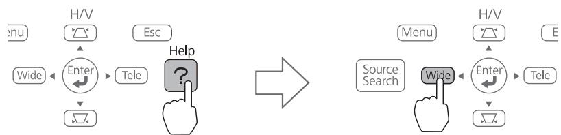
The guidance screen is displayed.

Open the air filter cover, and then adjust the focus using the focus lever
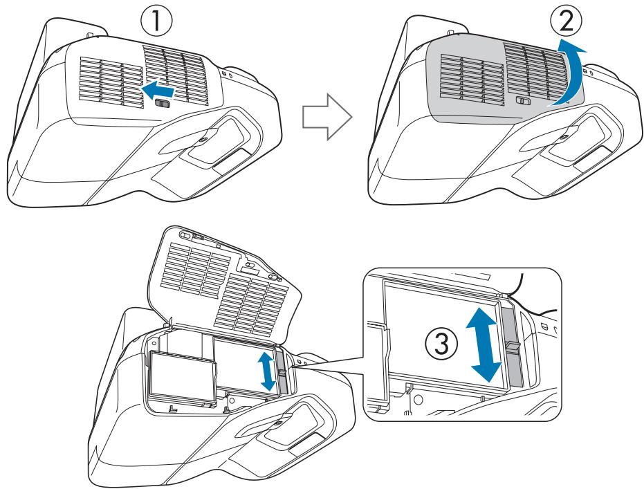
After you finish making adjustments, close the air filter cover.
5
Loosen the M4 screw (x1) with the hexagon wrench, and then adjust the horizontal roll with the adjustment dial

Repeat steps 5 to 10 as necessary.


After you finish making adjustments, tighten the M4 screw that you loosened.
6
Loosen the M4 screws (x2) with the hexagon wrench, and then adjust the horizontal rotation with the adjustment dial

A
B
After you finish making adjustments, tighten the M4 screws that you loosened.
7 LoosetheM4 screw the adjustment dial

A
B
After you finish making adjustments, tighten the M4 screw that you loosened.
8
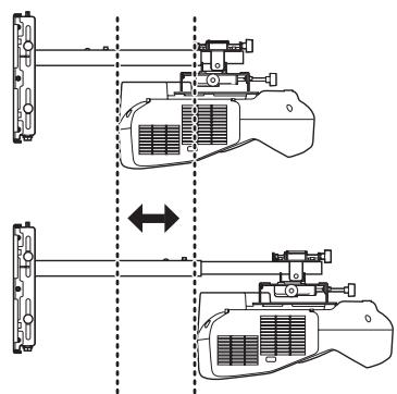
Loosen the M4 bolts (x2) with the hexagon wrench, and then adjust the horizontal slide
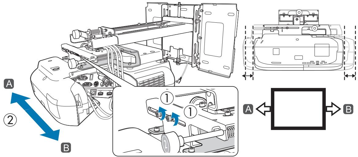
After you finish making adjustments, tighten the M4 bolts that you loosened.

Loosen the M4 bolts (x2) with the hexagon wrench, and then adjust the forward/backward slide
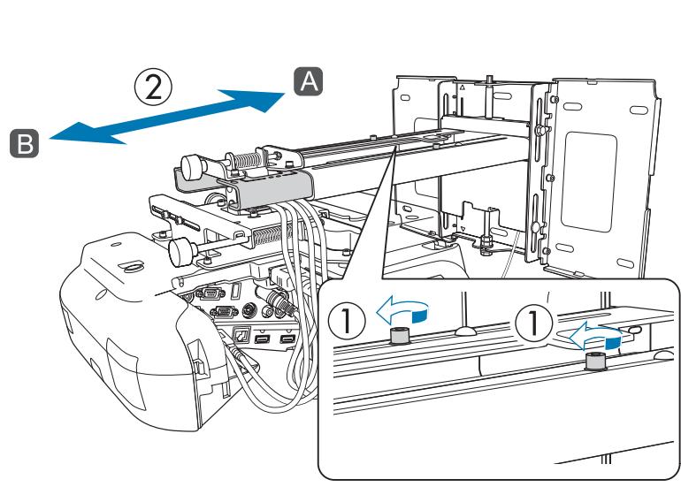
B
After you finish making adjustments, tighten the M4 bolts that you loosened.

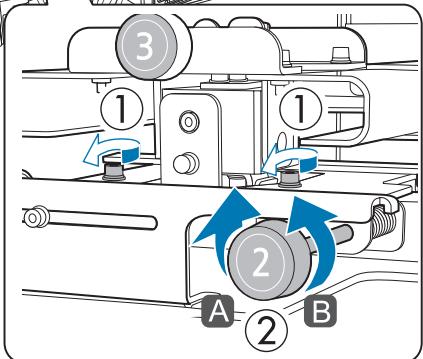
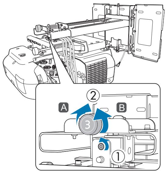
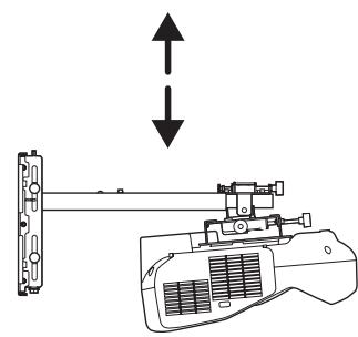
Loosen the M6 bolt (x1) with the open-ended spanner, and then adjust the vertical slide. Adjust the vertical slide with the hexagonal axis at the top or the bottom.
- Tightening the hexagonal axis at the top raises the setting plate, and loosening the axis lowers it.
- Tightening the M8 bolt at the bottom lowers the setting plate, and loosening the bolt raises it.
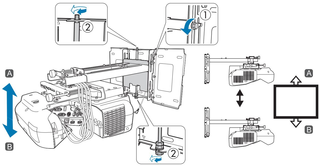
After you finish making adjustments, tighten the M6 bolt that you loosened.

Make sure that all of the bolts that you loosened in steps 5 to 10 are securely tightened

Warning
Tighten all bolts and screws firmly. Otherwise, the product may fall and cause personal injury or property damage.

Press the [Esc] button on the remote control or the control panel to remove the guidance screen

Fine-tuning the Focus

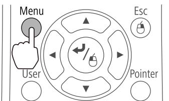
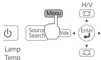
Turn on the projector, and then press the Menu button
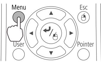
Using the Remote Control
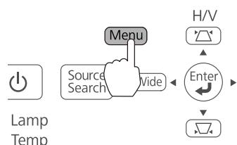
Using the Control Panel

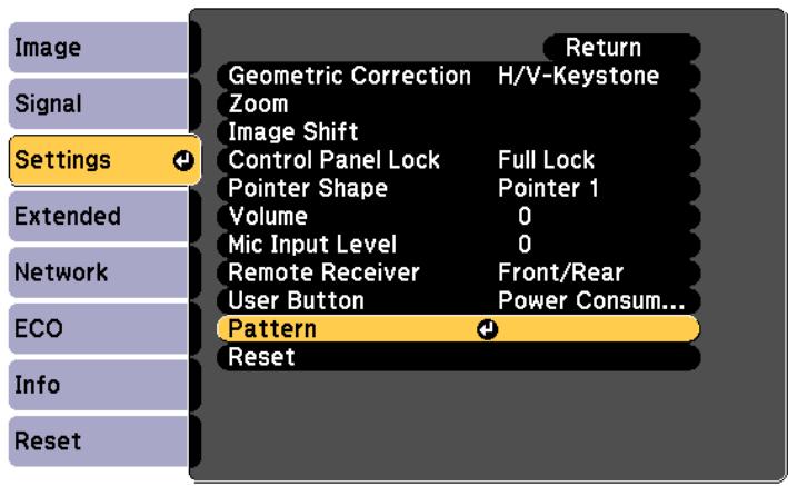
Select Pattern from Settings

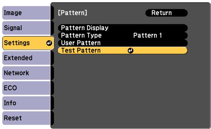
Select Test Pattern
When displaying on a 4:3 screen, set Pattern Type to Pattern 5, and then select Pattern Display.
4
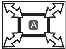
Adjust the focus to match the focus in the following figure (A)
Open the air filter cover, and then adjust the focus.
"Adjusting the Projection Position" p.40
When (A) is in focus, check the (B) areas. If any of the (B) areas are out of focus, adjust the focus until the (B) areas are uniform.
After you finish making adjustments, close the air filter cover.
5
Press the [Esc] button on the remote control or the control panel to remove the Test Pattern

Calibrating the pen
Check that adjusting the projected image is complete before you start calibrating the interactive pen.
"Adjusting the Projected Image" p.40
There are two methods available for calibrating the pen; Auto Calibration and Manual Calibration. When calibrating the pen for the first time after installing the projector, perform Manual Calibration for optimum calibration.
For the Auto Calibration method, see the projector's User's Guide (on the Document CD-ROM).
1
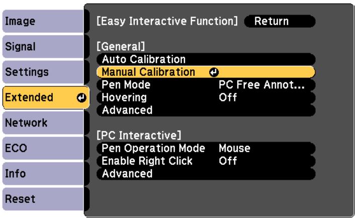
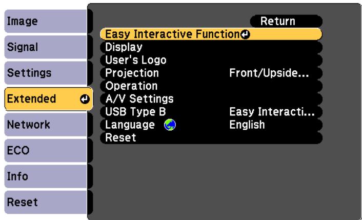
Turn on the projector, and then press the Menu button
2 Select Easy Interactive Function from Extended

3
Select Manual Calibration
4
Check that the screen is in focus, and then select Yes
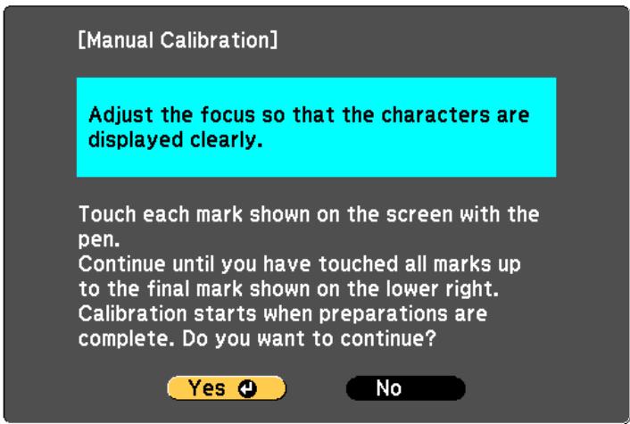
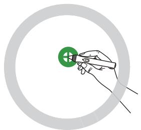
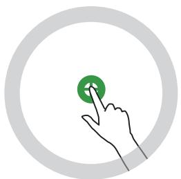
A green dot is displayed at the top left of the projection screen.
Touch the center of the dot with the pen tip button. The dot disappears and moves to the next position.
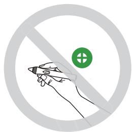
5
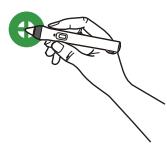


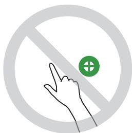
Make sure you touch the center of the dot. Otherwise, it may not be positioned correctly.

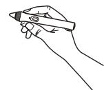
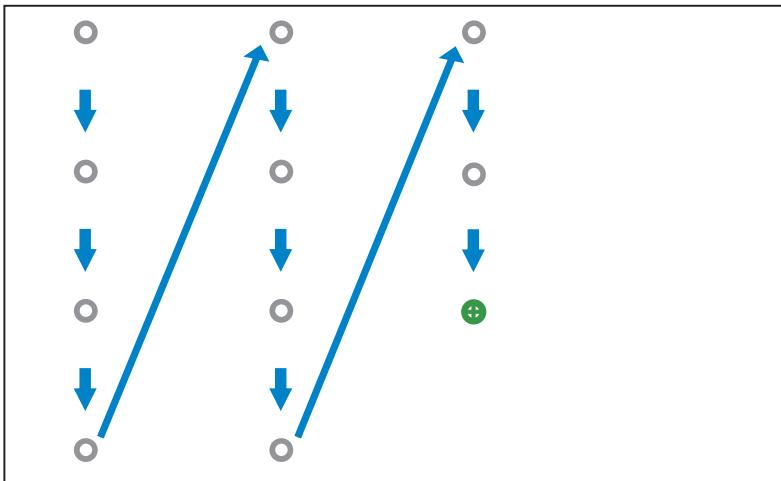
Repeat step 5 until all of the dots disappear
The dot appears at the top left first and then moves towards the bottom right.
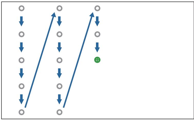
When all of the dots disappear, calibration is complete.

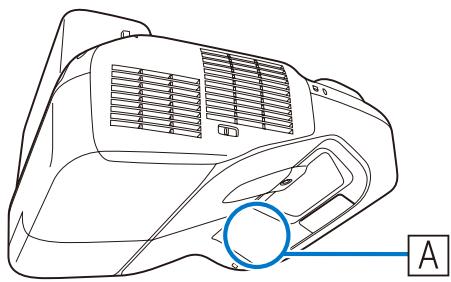
- Check that there are no obstacles between the interactive pen and the Easy Interactive Function receiver (A).
- If you touch the wrong position, press the [Esc] button on the remote control to return to the previous dot.
- To cancel calibration, hold down the [Esc] button for two seconds.
Attaching the Covers
1
Attach the wall plate covers
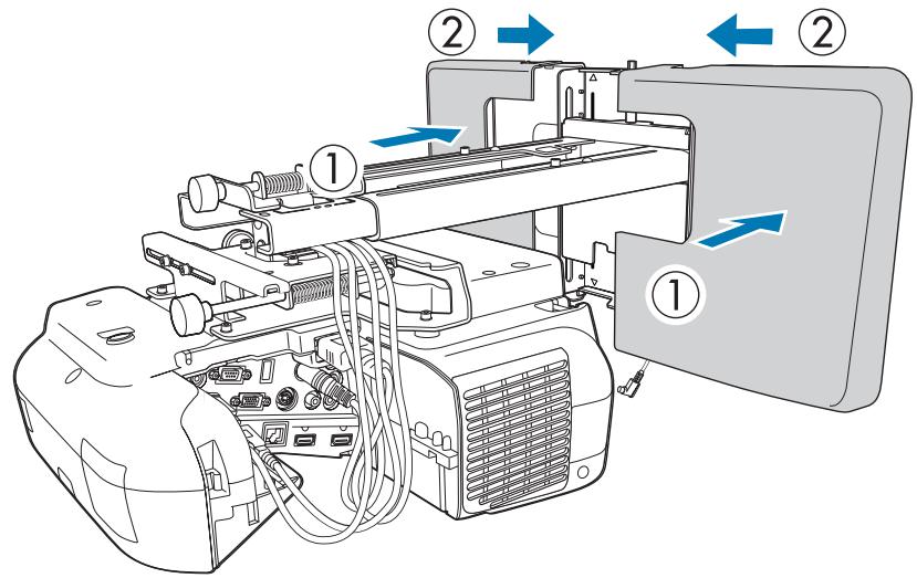

Depending on the cable configurations, you may need to cut notches (A) in the wall plate covers to route the cables. Perform deburring on the cut sides to smooth off any sharp edges.
Make sure you do not damage the cables when routing them through the cut holes.
Also, make sure you operate the cutter safely.
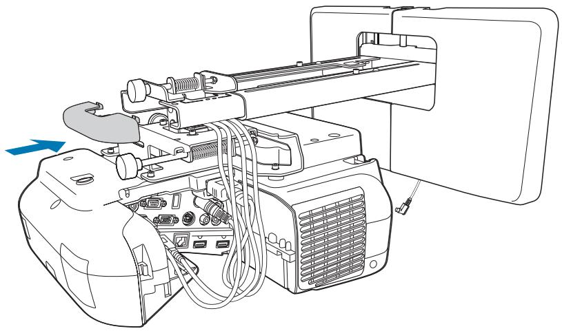
2
Place the end cap with the concave portion facing up
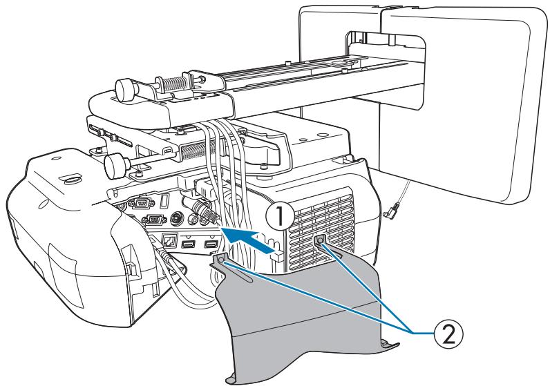
3 Attach the cable cover to the projector, and then secure it with the screws (x2)

Caution
Only a specialist should remove or reinstall the projector, including for maintenance and repairs. See the projector's User's Guide for instructions on maintenance and repairs.

Warning
- Never loosen the bolts and nuts after installation. Confirm that the screws have not become loose on a regular basis. If you find any loose screws, tighten them firmly. Otherwise, the product may fall and cause personal injury or property damage.
- Do not hang on this product or hang a heavy object on this product. If this product falls, it could cause death or personal injury.

Installing the Control Pad
Installation Procedure
See the following for the Control Pad installation location.
"Control Pad installation location" p.5
"When installing the Control Pad" p.19
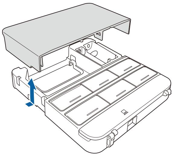
1 Remove the cable cover
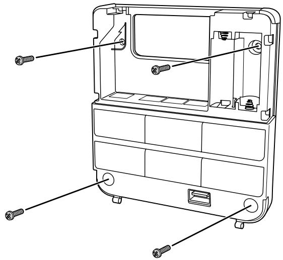
2
Check the installation location, and secure with commercially available M4 screws (20 mm x4)
Secure the Control Pad with commercially available M4 screws (20 mm x4)

Warning
- Secure so that the screws are not angled on the installation side.
- Make sure the Control Pad is firmly secured.
- Do not secure the Control Pad with double-sided sticky tape or magnets.

- We recommend checking the Control Pad operations before securing it with the screws.
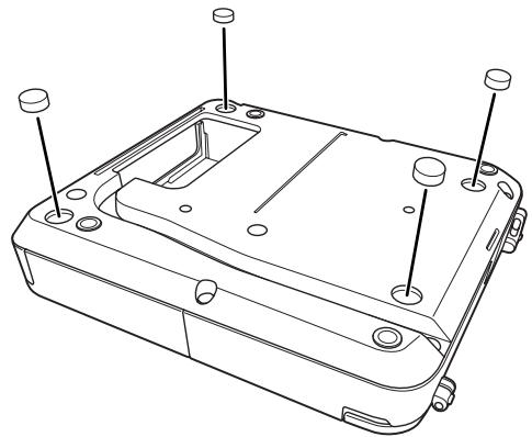
- When installing the Control Pad on a table, attach the rubber feet (x4) supplied to the base of the Control Pad to prevent it from slipping.
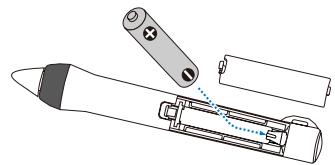
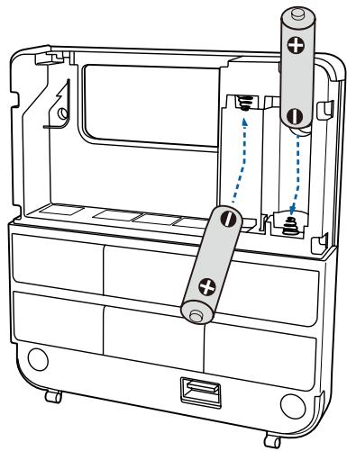
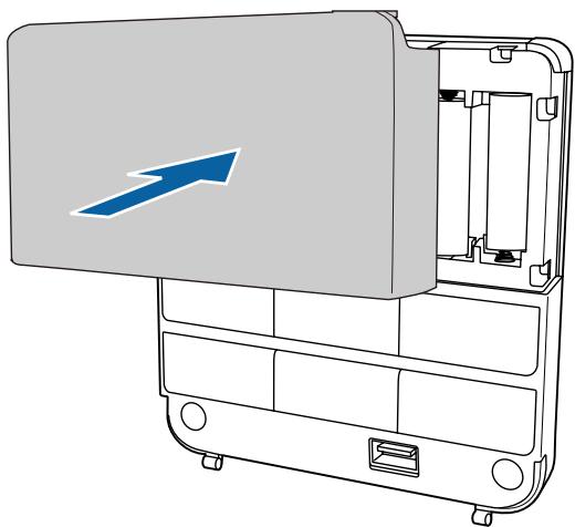
3
Supply power using the batteries supplied (x2)

Caution
Before handling the batteries, read the Safety Instructions on the Document CD-ROM.

- Obtain two AA size manganese or alkaline (recommended) batteries. Do not use any other type of battery. Rechargeable batteries cannot be used.
- When supplying power from the projector, connect the optional Remote control cable set (ELPKC28) to the projector's Remote port and the Control Pad's Remote port. When supplying power from the projector, do not install batteries in the Control Pad.
4
Connect the Control Pad ports to the cables connected to the projector as necessary.
See the following for the cable connection methods.
"ecessary cables when installing the Control Pad" p.28
5
Stick the port protection stickers supplied on the ports that are not being used by the Control Pad.
6
Attach the cable cover

Installing the Touch Unit (EB-1430Wi only)
Check that the following procedures have been completed before installing the Touch Unit.
- Installing the Projector (p.27)
Adjusting the Projected Image (p.40) - Calibrating the Interactive Pen (p.47)
About installation
- There are magnets built into the back of the Touch Unit. Normally, the Touch Unit should be installed by attaching the magnets to the screen.
- If the magnets cannot be attached to a screen, use commercially available M4 screws (x3).
- Attach the Touch Unit to the same level surface as the screen surface.
- Attach the Touch Unit to a flat, smooth, unwarped surface. If there is unevenness on the screen surface of more than 5 ~mm , the position of your fingers is not detected, and touch operations may not be performed correctly.
Installation Procedure
Install the Touch Unit, and then connect to the projector.

Caution
Only connect the Touch Unit to the EB-1430Wi. Do not connect it to any other projectors or devices.
1
Turn on the projector, and then press the Menu button
Using the Remote Control
Using the Control Panel
2
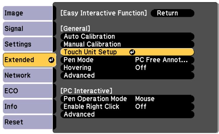
Select Easy Interactive Function from Extended
3
Select Touch Unit Setup
4
Select Installation Pattern
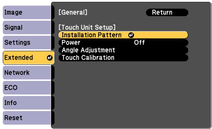
The installation pattern is displayed on the projected image.
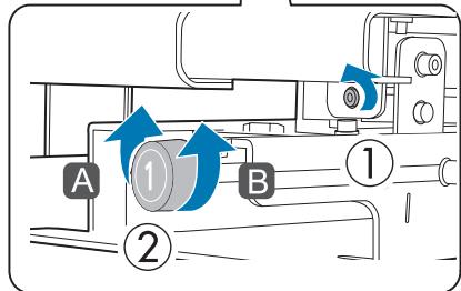
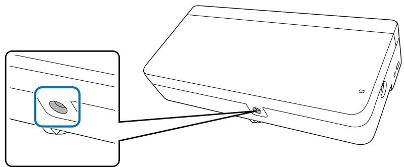
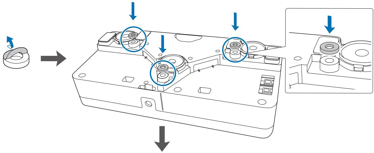
5
Loosen the screw at the bottom of the dial cover using a commercially available No.2 crosshead screwdriver
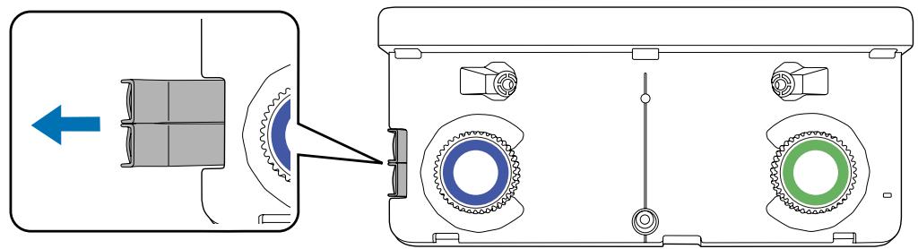
6
Slide the dial cover down to remove it
7
Remove the markers (x2) from the Touch Unit
8
Use the removed markers to perform angle adjustment for laser diffusion after installing the Touch Unit.
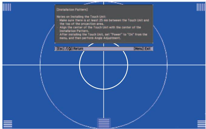
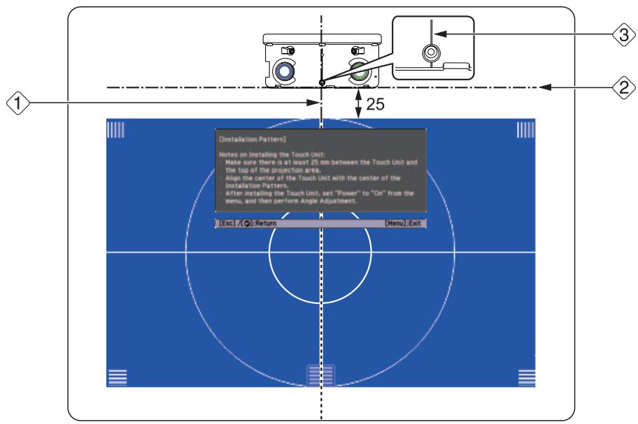
Determine the installation position for the Touch Unit
We recommend marking the following installation positions to make installation easier.
(1): Center line of installation pattern. Align with the center line of the Touch Unit (3).
(2): 25 mm from the top edge of the projected image. Align with the bottom edge of the Touch Unit.
[Unit: mm]

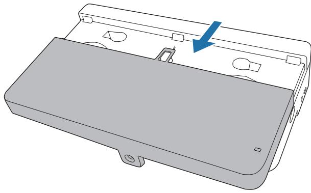
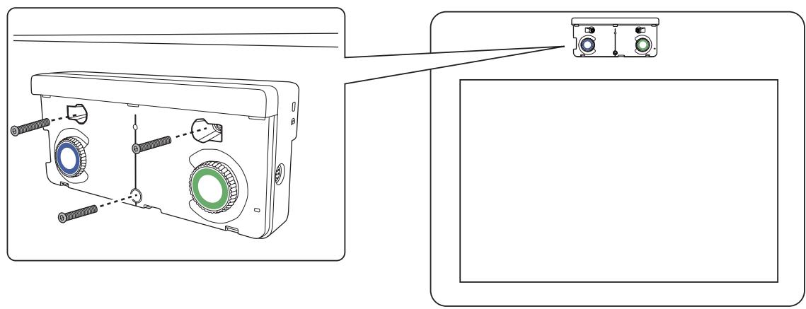
Secure the Touch Unit
- Magnetic screens: Place the back of the Touch Unit on the screen surface, and then secure.

Caution
When installing the Touch Unit on a magnetic surface, be careful not to trap your fingers or any other part of your body between the magnets and the installation surface. Powerful magnets are used which can cause injury if you trap your fingers.
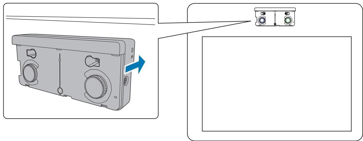
Non-magnetic screens: Attach spacers and secure with M4 screws (x3).
[Unit: mm]
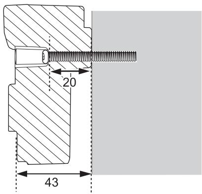
Screw hole cross-section
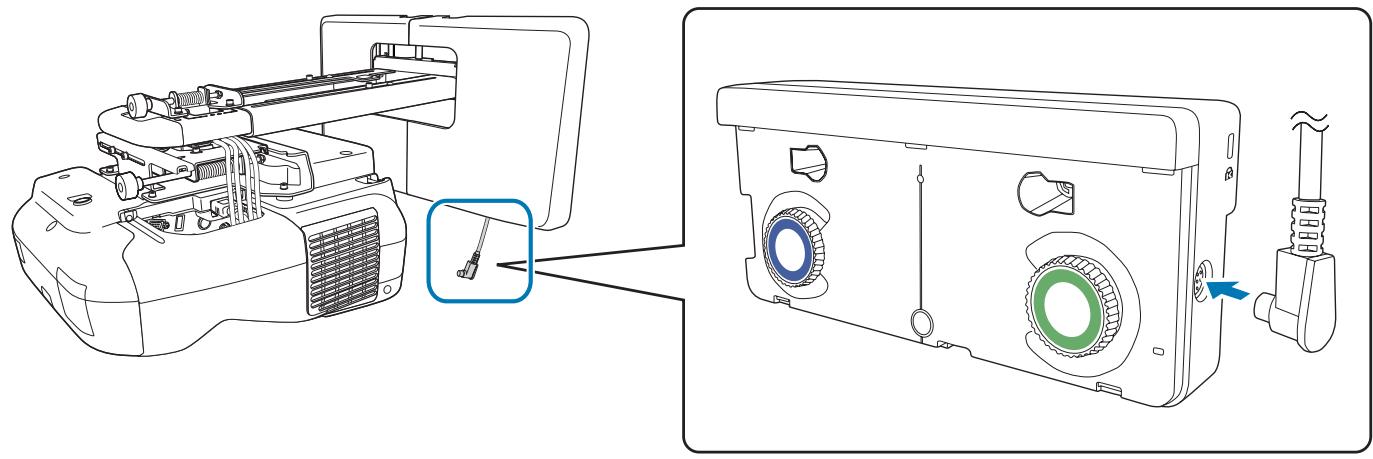
10
Connect the Touch Unit connection cable that is connected to the projector to the TCH port on the Touch Unit
Angle Adjustment
Adjust the angle of the laser light coming from the Touch Unit so that the Touch Unit can detect the position of your fingers.

Before adjusting the angle, make sure that interactive pen calibration is complete.
"Calibrating the pen" p.47
1
Select Easy Interactive Function in Extended from the projector's Configuration menu
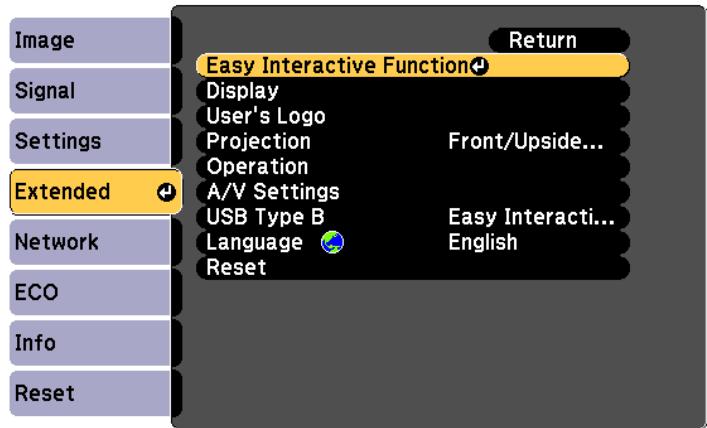
2
Select Touch Unit Setup
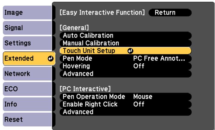

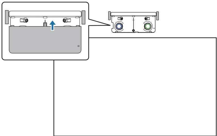
Set Power to On
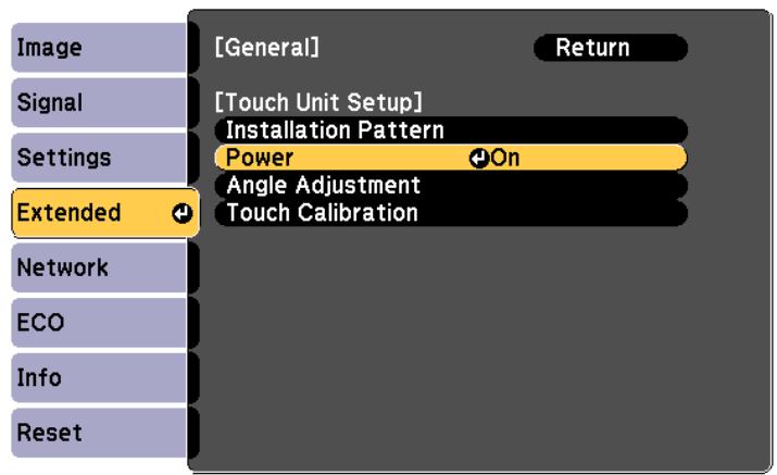
The Touch Unit power turns on and the indicator is lit blue.
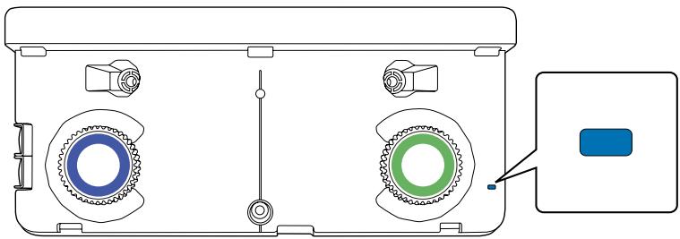

Warning
Do not look into the projector's projection window or the Touch Unit's laser diffusion ports. This could cause damage to eyesight due to the powerful laser light emitted.

When Power is set to On, the next time the projector is turned on, the Touch Unit automatically turns on.
4
Select Angle Adjustment
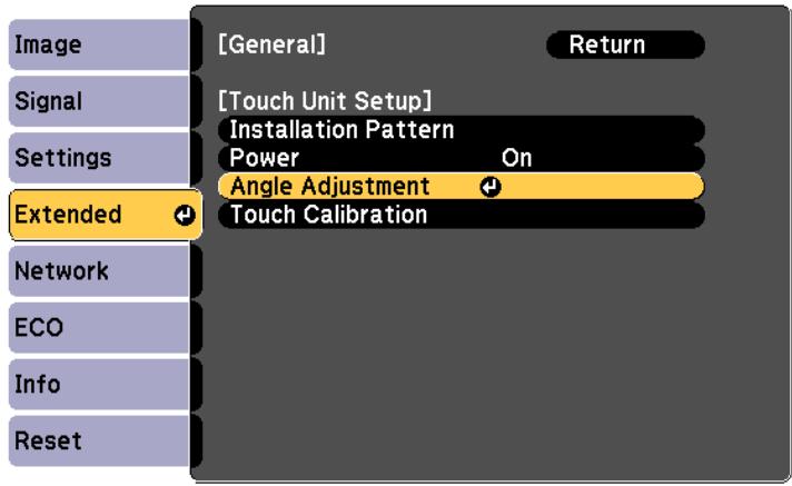
The following screen is displayed.

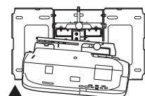
[Angle Adjustment] 1/4 Preparation

Before the adjustment, turn the Adjustment Dialis counterclockwise until the dial stops.

For the first time of Angle Adjustment, execute "Installation Pattern", and align the center of Touch Unit with the center. Make sure "Auto Calibration" or "Manual Calibration" has been done.
Begin Angle Adjustment when these steps are completed. Proceed to the next step.


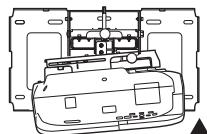
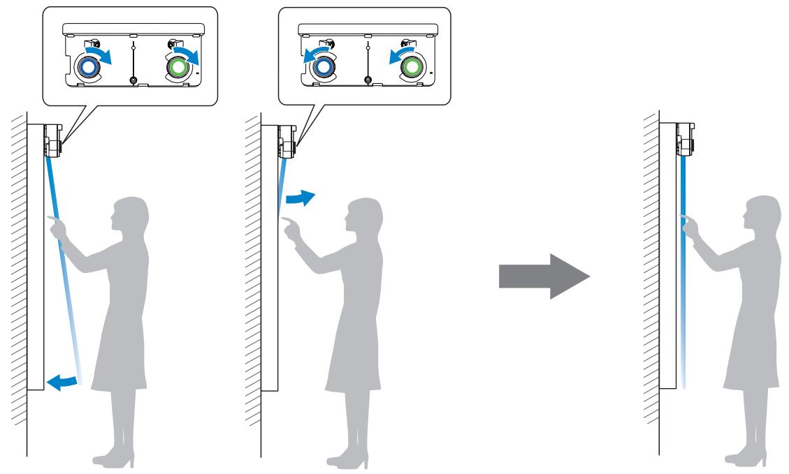
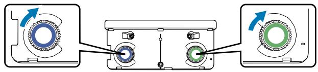
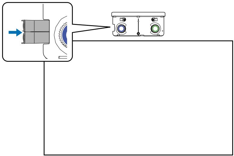
5
Turn the adjustment dials on the Touch Unit counterclockwise until you hear a clicking sound
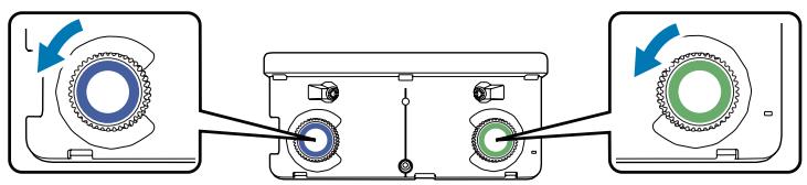
When you hear a clicking sound coming from the adjustment dial, stop turning, and then press the [] button on the remote control. The following screen is displayed.
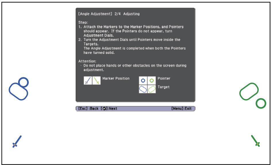
6
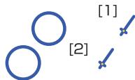
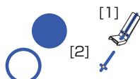
Attach the two markers that you removed from the Touch Unit to the marker positions ( ) on the projection screen
Match the positions so that the crosses ( ) for the markers overlap with the points ( ) for the ( × × ) ( × × ) .
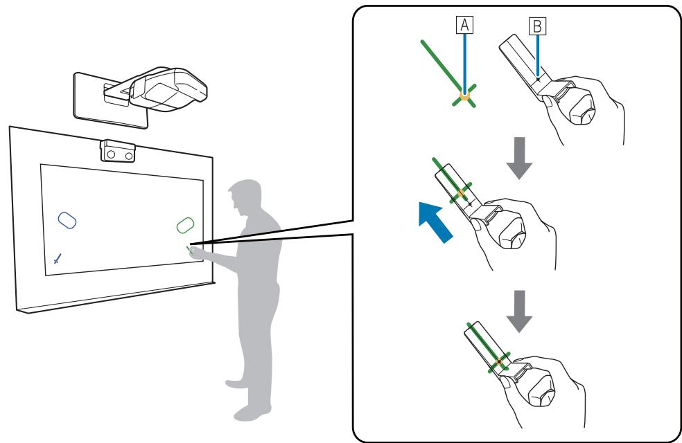
When pointers (O) (O) with the same color as the marker positions are displayed on the left and right of the projection screen, attach the markers to the projection screen.
- Magnetic screens: Place the bottom of the markers onto the screen.
- Non-magnetic screens: Use the supplied tape to secure the markers. Attach the tape so that the either end of marker does not come loose off the screen.
| Correct | Incorrect |

Do not place anything other than the markers near the projected image during angle adjustment. If other objects are on the projected image, angle adjustment may not be performed correctly.
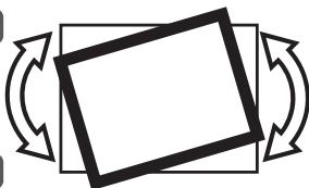
7
Turn the adjustment dials on the Touch Unit to move the pointers ( ) ( ) so that they overlap with the target ( ) ( ) of the same color on either side
When you turn the adjustment dial clockwise, the pointer moves diagonally up towards the center of the projected image.
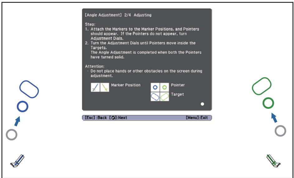
When you turn the adjustment dial counterclockwise, the pointer moves diagonally down away from the center of the projected image.
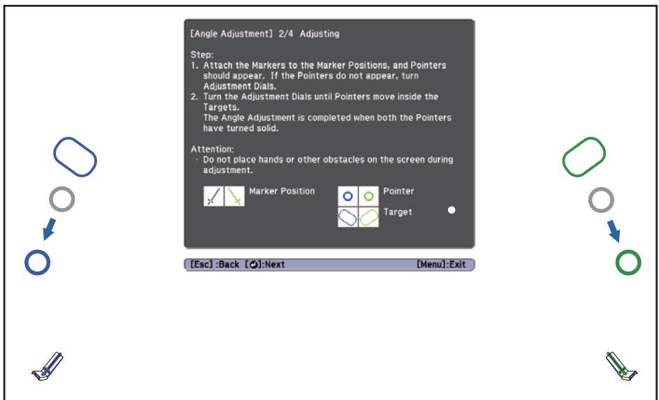
When the pointers overlap in the correct position, the colors become solid ( ) ( ).

- If you hear a clicking sound from the dial, the pointer does not move any further.
- When turning the dials, make sure shadows from your arm or body do not overlap with the markers.
8
When the pointers on the left and right become solid colors ( ) ( ), press the [ ] button on the remote control
The following screen is displayed.
[Angle Adjustment] 3/4 Confirmation
Confirm the result of the Angle Adjustment.
Step:
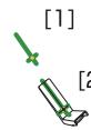
1. Place the Markers on the Marker Positions [1]. Make sure the both of circles are filled.
2. Place the Markers on the Marker Positions [2]. Make sure the both of circles are filled.
Attention
- If the circles are not filled, go back to the "1/4 Preparation" step. Turn the Adjustment Dials counterclockwise until they stop. Perform the Angle Adjustment again.
![EPSON EB-1420WI - [Angle Adjustment] 3/4 Confirmation - 1](/content/2019/08/104066/images/88a7617dbc4c55234a1c34902997666dc22ecefb62be1d297a3686d4c54a5c1a.jpg)
Marker Position
![EPSON EB-1420WI - [Angle Adjustment] 3/4 Confirmation - 2](/content/2019/08/104066/images/f53cce85427c9f9c135811716c3a1d46b5eeb3ba464c8814728ced62bacacbd9.jpg)
![EPSON EB-1420WI - [Angle Adjustment] 3/4 Confirmation - 3](/content/2019/08/104066/images/28ef43b231e17afd1461a29cec2ef43d3c47c18101e2a67b4cbb38b7b61085ca.jpg)
![EPSON EB-1420WI - [Angle Adjustment] 3/4 Confirmation - 4](/content/2019/08/104066/images/80372c790a04fa17ca58753595b0bdfb6791542c7b32c0984d35104f0d4dce45.jpg)
[Esc]:Back O:Next
9
Place the markers at the top marker positions [1] ( ) ( )
When angle adjustment is performed correctly, the upper pointers become solid colors ( Ⓞ ) ( Ⓞ ).
[Angle Adjustment] 3/4 Confirmation
Confirm the result of the Angle Adjustment.
- Place the Markers on the Marker Positions [1]. Make sure the both of circles are filled.
- Place the Markers on the Marker Barriers [3]. Make sure the
- Place the Markers on the Marker Positions [2]. Make sure the both of circles are filled.
Attention:
If the circles are not filled, go back to the "1/4 Preparation" step. Turn the Adjustment Dials counterclockwise until they stop. Perform the Angle Adjustment again.
![EPSON EB-1420WI - [Angle Adjustment] 3/4 Confirmation - 1](/content/2019/08/104066/images/5d515cae72fa0705de98572dbba35d3846568887c39d2a9e9de6b98a1ecbe69c.jpg)
Marker Position
![EPSON EB-1420WI - [Angle Adjustment] 3/4 Confirmation - 2](/content/2019/08/104066/images/42fd8402014e552467f9984fd4c47f344198e4ad0467593b3a244344a5a47671.jpg)
![EPSON EB-1420WI - [Angle Adjustment] 3/4 Confirmation - 3](/content/2019/08/104066/images/df9d17ef6d7027788874266189efa7e640ee593cb3caf710709bb48cb993a91f.jpg)
[2]
[Esc]:Back O:Next
If the upper pointers do not become solid colors ( ), start again from step 4.
10
Place the markers at the bottom marker positions [2] ( ) ( )
When angle adjustment is performed correctly, the bottom pointers become solid colors ( Ⓞ ) ( Ⓞ ).
![EPSON EB-1420WI - Place the markers at the bottom marker positions [2] ( ) ( ) - 1](/content/2019/08/104066/images/7b95dbd83ec82764d5d0da839bdcc0920592a93a9b838c76d935eb0942167dca.jpg)
[Angle Adjustment] 3/4 Confirmation
Confirm the result of the Angle Adjustment.
1. Place the Markers on the Marker Positions [1]. Make sure the marker is positioned to fill
2. Place the Markers on the Marker Positions [2]. Make sure the both of circles are filled,
Attention:
If the circles are not filled, go back to the "1/4 Preparation" step. Turn the Adjustment Dials counterclockwise until they stop. Perform the Angle Adjustment again.

Marker Position
[Esc]:Back O:Next

If the bottom pointers do not become solid colors ( ) ( ), start again from step 4.
11
When you have finished checking, remove the markers, and then press the [ ] button on the remote control
The following screen is displayed.
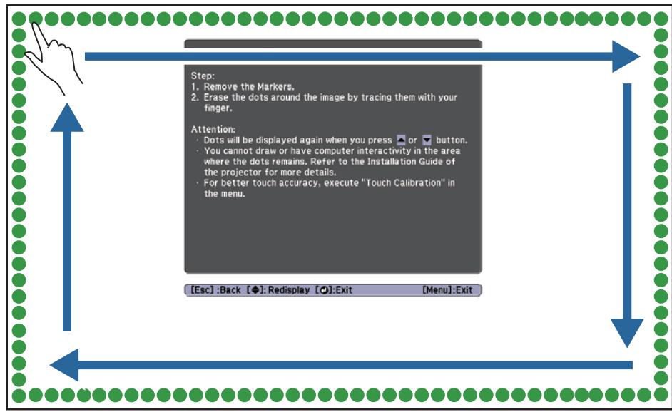
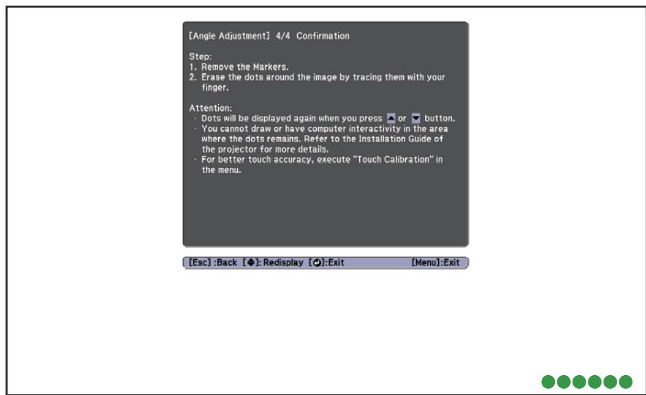
[Angle Adjustment] 4/4 Confirmation
Step:
1. Remove the Markers.
2. Erase the dots around the image by tracing them with your finger.
Attention:
- Dots will be displayed again when you press or button. You cannot draw or have computer interactivity in the area where the dots remain. Refer to the Installation Guide of the projector for more details. For better touch accuracy, execute "Touch Calibration" in the menu.
[Fsc]
:Back []:Redisplay []:Exit
Trace the dots ( ) with your finger
When angle adjustment is performed correctly, the dots you have traced disappear.

Touch operations may not perform correctly if you are wearing artificial nails or nail polish, or if your fingers are obstructed by bandages and so on.
When all of the dots have disappeared, press the [ ] button on the remote control, and then go to step 14.
If some dots remain as shown in the following figure, check the following points.
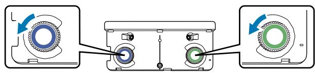
- Remove any obstacles that are around the projection screen. After removing any obstacles, press the [ ] or [ ] button on the remote control, and then perform step 12 again.
- If the dots still remain after removing obstacles, turn the adjustment dials about a quarter turn counterclockwise. Next, press the [ ] or [ ] button on the remote control, and then perform step 12 again.
- Go to step 13 if dots still remain even after performing this step, or there are obstacles that cannot be removed such as whiteboard trays or frames.
Stick the infrared deflectors supplied so that the laser is not reflected by the obstacle (only if there is an obstacle near the projection screen that cannot be moved)
Stick the deflectors between the dots and the obstacle. Adjust the number of deflectors according to the number of dots.
Remove the tape from the back of the infrared deflectors, and stick them on the screen.
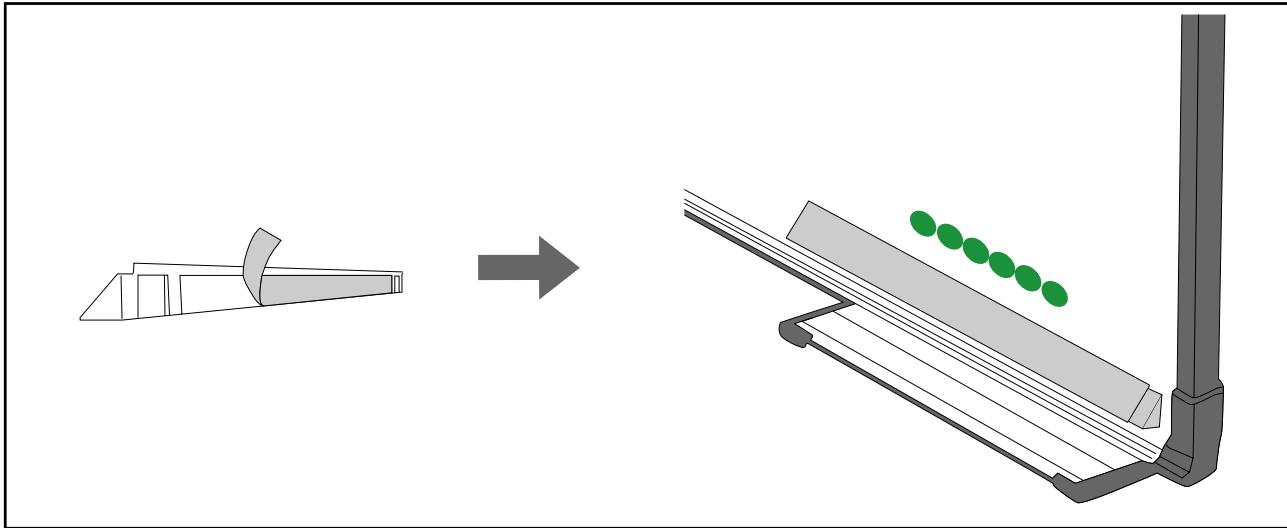

- Do not remove an infrared deflector once it has been stuck in place. This can weaken the adhesive strength of the tape.
- Do not stick tape or place anything on the infrared deflectors. The infrared deflector will not function correctly.
After placing the infrared deflectors, press the [ ] or [ ] button on the remote control, and then perform step 12 again.
If the dots do not disappear even after attaching the infrared deflectors, turn the adjustment dials about a quarter turn counterclockwise. Next, press the [ ] or [ ] button on the remote control, and then perform step 12 again.
If the dots do not disappear even after performing the above procedures, contact your local dealer from the Epson Projector Contact List provided on the Document CD-ROM.
Store the markers in the Touch Unit
15
Attach the labels at the tabs on either side of the Touch Unit Match the center of the labels with the tabs on the Touch Unit.

If the Touch Unit moves out of position, use the labels to reinstall it at the correct position.
16
Attach the dial cover, and then tighten the screw at the bottom of the dial cover.
Touch Calibration
Perform touch calibration so that the projector can recognize touch operations precisely.
1
Press the projector's Menu button
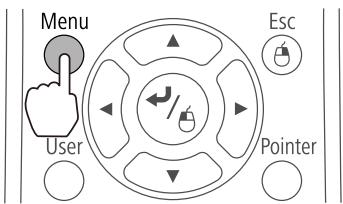
Using the Remote Control
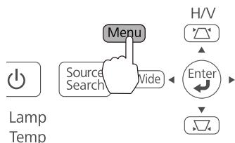
Using the Control Panel
2 Select Easy Interactive Function from Extended
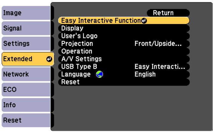
3 Select Touch Unit Setup
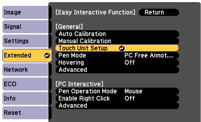
4 Select Touch Calibration
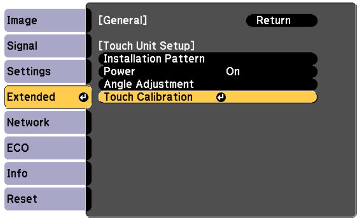
The focus adjustment message is displayed.
5
Check that the screen is in focus, and then select Yes
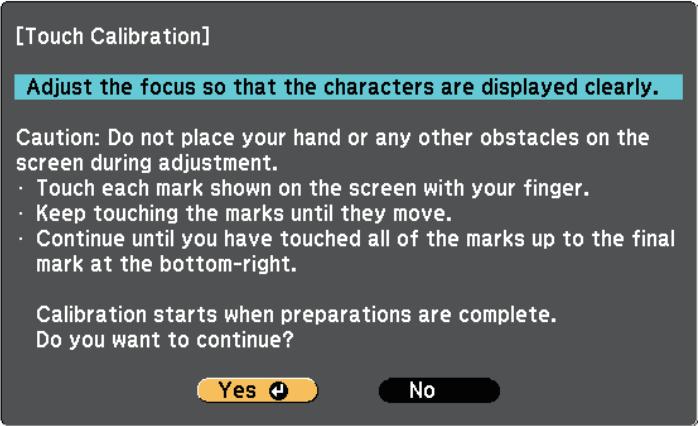
A dot is displayed at the top left of the projection screen.
6
Touch the center of the dot with your finger
When the dot disappears and moves to the next position, remove your finger.


- Make sure you touch the center of the dot. Otherwise, it may not be positioned correctly.
- Do not touch with anything else except the tip of your finger.
Repeat step 6 until all of the dots disappear
7
When all of the dots disappear, touch calibration is complete.

- If you touch the wrong position, press the [Esc] button on the remote control or control panel. This returns you to the previous dot. You cannot go back by two dots.
- To cancel touch calibration, hold down the [Esc] button for two seconds.
- It may take several seconds after all of the dots have disappeared until touch calibration is complete.

Batch Setup Function
Once the Configuration menu content has been set for one projector, you can use it to perform batch setup for multiple projectors (batch setup function). The batch setup function is only for projectors with the same model number.
Use one of the following methods.
- Setup using a USB flash drive.
- Setup using EasyMP Network Updater.
This guide explains how to use a USB flash drive.

-
The following content is not reflected by the batch setup function.
-
Network menu settings (except for the Mail menu and the Others menu)
-
Lamp Hours and Status from the Info menu
-
Perform batch setup before adjusting the projected image. Adjustment values for the projected image, such as Keystone, are reflected by the batch setup function. If batch setup is performed after adjusting the projected image, the adjustments you made may change.
- By using the batch setup function, the registered User's Logo is set for the other projectors. Do not register confidential information and so on as the User's Logo.

Caution
Performing batch setup is the customers responsibility. If batch setup fails due to a power failure, communication error, and so on, the customer is responsible for any repair costs incurred.
Saving settings to the USB flash drive

- Use a FAT format USB flash drive.
- The batch setup function cannot be used by USB flash drives that incorporate security functions. Use a USB flash drive that does not incorporate security functions.
- The batch setup function cannot be used by USB card readers or USB hard disks.
1 Disconnect the power cord from the projector, and check that all of the projector's indicators have turned off

Connect the USB flash drive to the projector's USB-A port

- Do not connect a USB flash drive to the port.
-
Connect the USB flash drive directly to the projector. If the USB flash drive is connected to the projector through a USB hub, the settings may not be saved correctly.
-
Connect an empty USB flash drive. If the USB flash drive contains data other than the batch setup file, the settings may not be saved correctly.
- If you have saved a batch setup file from another projector to the USB flash drive, delete the file or change the file name. The batch setup function cannot overwrite a batch setup file.
- The file name for the batch setup file is PJCONFDATA.bin. If you need to change the file name, add text after PJCONFDATA. If you change the PJCONFDATA section of the file name, the projector may not be able to recognize the file correctly.
- You can only use single-byte characters for the file name.
3
While holding down the [Esc] button on the remote control or the control panel, connect the power cord to the projector
The status indicator and the power indicator turn blue, and the lamp indicator and the temperature indicator turn orange.
When all of the projector's indicators turn on, release the [Esc] button.
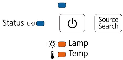
When all of the indicators start flashing, the batch setup file is being written.

Caution
- Do not disconnect the power cord from the projector while the file is being written. If the power cord is disconnected, the projector may not start correctly.
- Do not disconnect the USB flash drive from the projector while the file is being written. If the USB flash drive is disconnected, the projector may not start correctly.
When writing completes normally, the projector turns off, and only the power indicator is lit blue.
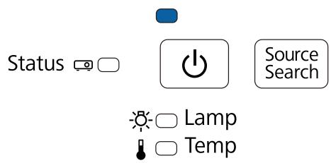
When the power turns off, remove the USB flash drive.
Reflecting saved settings to other projectors
1
Disconnect the power cord from the projector, and check that all of the projector's indicators have turned off
2
Connect the USB flash drive containing the saved batch setup file to the projector's USB-A port

- Do not connect a USB flash drive to the port.
- When the USB flash drive contains 1 to 3 types of batch setup files, the file is reflected to the projector with the same model number. If there are multiple files for a projector with the same model number, the settings may not be reflected correctly.
- When there are four or more types of batch setup files on the USB flash drive, the settings may not be reflected correctly.
- Do not store any data except for the batch setup file on the USB flash drive. If the USB flash drive contains data other than the batch setup file, the settings may not be reflected correctly.
3
While holding down the Menu button on the remote control or the control panel, connect the power cord to the projector
The status indicator and the power indicator turn blue, and the lamp indicator and the temperature indicator turn orange.
When all of the projector's indicators turn on, release the Menu button. The indicators turn on for approximately 75 seconds.
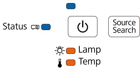
When all of the indicators start flashing, the settings are being written.

Caution
- Do not disconnect the power cord from the projector while the settings are being written. If the power cord is disconnected, the projector may not start correctly.
- Do not disconnect the USB flash drive from the projector while the settings are being written. If the USB flash drive is disconnected, the projector may not start correctly.
When writing completes normally, the projector turns off, and only the power indicator is lit blue.
When the power turns off, remove the USB flash drive.
When Setup Fails
| Check | Remedy |
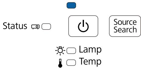
| Are the lamp indicator and the tempera-ture indicator flashing orange quickly?Status ☑ ☐ ☐Source SearchLampTemp | The batch setup file may be corrupt, or the USB flash drive may not be connected correctly. Disconnect the USB flash drive, unplug and then plug in the projector's power cord, and then try again. |
| Are the power indicator and the status in-dicator flashing blue quickly, and the lamp indicator and the temperature indicator flashing orange quickly? | Writing the settings may have failed and an error may have occurred in the projector's firmware. Stop using the projector, remove the power plug from the electrical outlet, and contact your local dealer or the nearest address provided in the Epson Projector Contact List. |
| Status | Source Search |
| Lamp | Temp |

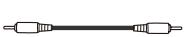
Using the Interactive Function when Multiple Projectors are Installed
When using the interactive pen in the same room as multiple projectors, infrared interference may cause pen operations to become unstable. Interactive pen operations are stabilized by linking the projectors using cables.
By using the optional Remote control cable set (ELPKC28), you can connect the SYNC ports on the projectors in series. After connecting the ports, set Extended - Easy Interactive Function - Advanced - Sync of Projectors to Wired from the Configuration menu.
For details, see the projector's User's Guide (on the Document CD-ROM).

- The SYNC port has an IN and OUT socket. When you connect one end of the cable to an IN socket, connect the other end to an OUT socket.
- When connecting three or more projectors, you do not need to connect the first projector to the last projector.

.

Out

In
In

Out

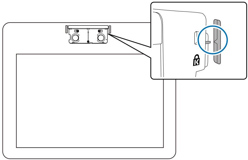
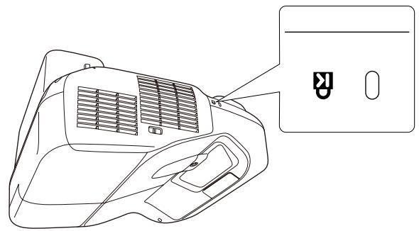
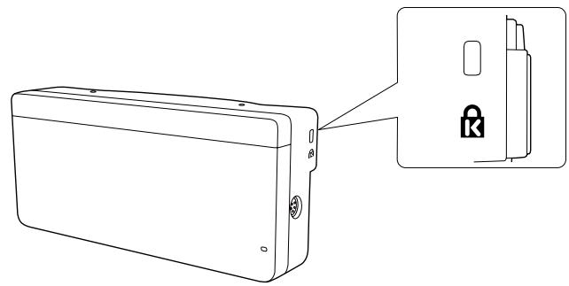
Attaching a Security Cable
A commercially available theft-prevention wire lock can be attached to this product.
Pass the wire for the theft-prevention wire lock through the security cable installation points on the projector and the setting plate. See the user's guide supplied with the wire lock for locking instructions.
The security slot on this product is compatible with the Microsaver Security System manufactured by Kensington. See the following for more details on the Microsaver Security System.
http://www.kensington.com/
Projector
Touch Unit (EB-1430Wi only)

General Notice
OS X is a trademark of Apple Inc.
Microsoft and Windows are trademarks or registered trademarks of Microsoft Corporation in the United States and/or other countries.
©SEIKO EPSON CORPORATION 2014. All rights reserved.
Indication of the manufacturer and the importer in accordance with requirements of directive 2011/65/EU (RoHS)
Manufacturer: SEIKO EPSON CORPORATION
Address: 3-5, Owa 3-chome, Suwa-shi, Nagano-ken 392-8502 Japan
Telephone: 81-266-52-3131
Importer: SEIKO EUROPE B.V.
Address: Azie building, Atlas ArenA, Hoogoorddreef 5, 1101 BA Amsterdam Zuidoost The Netherlands
Telephone: 31-20-314-5000
EB-1430Wi
EB-1420Wi
Plaque murale
Cache de la plaque murale
Control Pad (dimensions externes/poids)
[Unité : mm]
Determine the distance of projection, plus passes the cables at travers the plaque installation
©SEIKO EPSON CORPORATION 2014. All rights reserved.
Indication of the manufacturer and the importer in accordance with requirements of directive 2011/65/EU (RoHS)
Manufacturer: SEIKO EPSON CORPORATION
Address: 3-5, Owa 3-chome, Suwa-shi, Nagano-ken 392-8502 Japan
Telephone: 81-266-52-3131
Importer: SEIKO EUROPE B.V.
Address: Azië building, Atlas ArenA, Hoogoorddreef 5, 1101 BA Amsterdam Zuidoost The Netherlands
Telephone: 31-20-314-5000
EB-1430Wi
EB-1420Wi
Guía de instalación

©SEIKO EPSON CORPORATION 2014. All rights reserved.
Indication of the manufacturer and the importer in accordance with requirements of directive 2011/65/EU (RoHS)
Manufacturer: SEIKO EPSON CORPORATION
Address: 3-5, Owa 3-chome, Suwa-shi, Nagano-ken 392-8502 Japan
Telephone: 81-266-52-3131
Importer: SEIKO EUROPE B.V.
Address: Azië building, Atlas ArenA, Hoogoorddreef 5, 1101 BA Amsterdam Zuidoost The Netherlands
Telephone: 31-20-314-5000