
SZI 1019 A - Electric heater SENNHEISER - Free user manual and instructions
Find the device manual for free SZI 1019 A SENNHEISER in PDF.

| Product type | Infrared radiator for wireless sound reinforcement |
| Dimensions (W x D x H) | 330 x 230 x 90 mm |
| Weight | approx. 2.2 kg |
| Power supply | 115/220 V (reversible by soldering), 50-60 Hz |
| Current consumption in operation | 220 V: 150 mA; 115 V: 380 mA |
| Standby consumption | 220 V: 15 mA; 115 V: 18 mA |
| Fuse | 220 V: 0.63 A; 115 V: 1 A |
| Number of infrared diodes | 143 (12 lines) |
| Average radiated power | 2.3 W |
| Wavelength | approx. 950 nm |
| Input impedance | approx. 5 kΩ |
| HF input voltage | 30 mV - 3 V |
| Automatic switch-on threshold | 30 mV |
| Input/output connectors | BNC sockets |
| Maximum number of radiators in series | 100 (max cable length 1500 m) |
| Min. distance radiator-receiver | 2 m |
| Mounting accessories | Thread 5/8"×27G with reduction 3/8" or 1/2"; swivel joint GZG 1019 A; bar MZS 1019 |
| Connecting cables (coaxial) | GZL 1019 A1 (1 m), GZL 1019 A5 (5 m), GZL 1019 A10 (10 m) |
| Delivery contents | 1 radiator, 1 mains cable (5 m) |
| Maintenance | Keep ventilation slots free; have a defective diode line repaired as soon as possible |
| Safety | Use the fuse appropriate for the voltage; observe the rated voltages |
| Repairability | Diode lines individually repairable; spare parts available (fuses, diodes, cables) |
Frequently Asked Questions - SZI 1019 A SENNHEISER
User questions about SZI 1019 A SENNHEISER
0 question about this device. Answer the ones you know or ask your own.
Ask a new question about this device
Download the instructions for your Electric heater in PDF format for free! Find your manual SZI 1019 A - SENNHEISER and take your electronic device back in hand. On this page are published all the documents necessary for the use of your device. SZI 1019 A by SENNHEISER.
USER MANUAL SZI 1019 A SENNHEISER
Example for positioning and alignment of radiators
The SZI 1019 A is an infrared power radiator. Within a wireless infrared sound transmission system, it has the task of converting the electrical signals supplied by an infrared control transmitter into invisible infrared light and radiating this into the room.
If this is your first contact with infrared technology, the following picture will help you to understand the layout of such an infrared system.
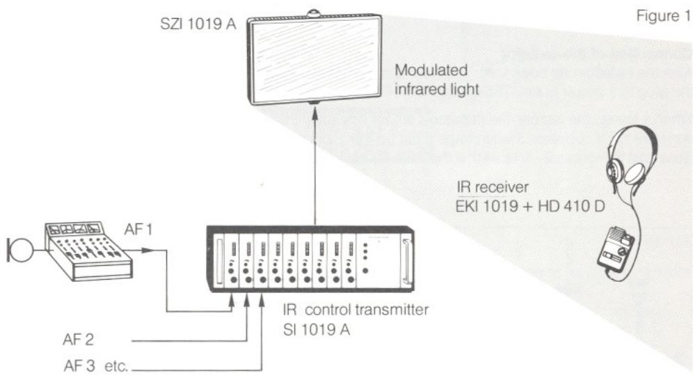
First, for the technically minded, a few words on the technology of the radiator: the SZI 1019 A has a built-in power supply unit and is thus independent of external supply units. This solution has the advantage that time and material costs during installation of the radiator can be kept very low. The radiator is switched automatically by the carrier signal generated by the control transmitter. This signal drives 143 infrared diodes in the SZI 1019 A, which radiate the signal in the form of modulated infrared light. The diodes are arranged in 12 rows. For rapid functional checking, a red LED is allocated to each diode row and lights if the row fails. Connection of the signal from the control transmitter to the radiator is carried out with commercially available 50 coaxial cables.
Operation
Single channel and multi-channel operation
If the radiator is used in a single channel (mono) system, set switch ③ to position "Mono". This increases the radiated power for single channel operation by approximately 30% For multi-channel systems, set the switch to "Multi-Channel".
Installation of the radiator
The radiator is equipped with two 5/8'' x 27 G threaded inserts for mounting on tripods or for wall or ceiling mounting. Each threaded insert also has an adapter which permits connection of the radiator to 3/8'' or 1/2'' threads.
When it leaves the factory, the radiator is prepared for use with 38 threads. If you wish to convert to 12 or 58 × 27 G threads, then simply reverse the adapter or remove it completely, respectively.
Further mounting aids offered by Sennheiser are the ball joint GZG 1019 A and adapter bar MZS 1019. The ball joint should always be used, as it permits optimum alignment of the radiator. The adapter bar is used wherever two radiators are to be mounted on a tripod or one wall or ceiling attachment (see "Installation examples").
Important note: In all cases, ensure that the radiator receives sufficient ventilation.
In order to permit optimum radiation of the infrared light, the radiator should be installed, wherever possible, such that there are no obstacles between it and the infrared receivers. This can be achieved by mounting the radiator as high as possible, and tilting it slightly downwards. In order to ensure that the signal is as uniform as possible within the room, the radiators should be spread around the room. Please note that minimum distance between the radiator and an infrared receiver should be 2m , as there is otherwise a danger of over driving the receiver input stage, which can result in distortion of the signal.
Connection of the radiator
After the radiator has been installed, insert the enclosed 5m mains cable in socket 4 and connect the plug to a power outlet. The radiator is now in standby mode.
When it leaves the factory, the radiator is set for operation from 220V / 50Hz supplies. For operation from 115-V supplies, 3 wire straps must be repositioned within the radiator. The procedure is illustrated in Figures 2-4. Note that the 0.63 A fuse has to be replaced by a 1 A fuse.
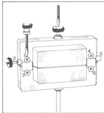
Figure 2
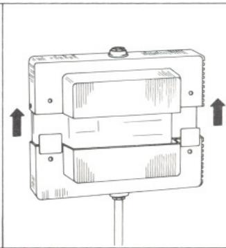
Figure 3
Figure 4
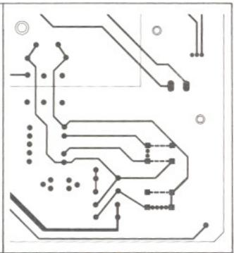
-115V 220V
After connection of the radiator to the power outlet, it is only necessary to establish the connection between RF input ⑤ of the SZI 1019 A and the RF output of the control transmitter. The following coaxial cables are available for this purpose: GZL 1019 A 1 (BNC/BNC, length: 1 m), GZL 1019 A 5 (BNC/BNC, length: 5 m), and GZL 1019 A 10 (BNC/BNC, length: 10 m). The cables can also be connected together with the aid of the double BNC socket GZV 1019 A. For permanent installation, commercially available 50 coaxial cables such as RG 58 can be used. If more than one SZI 1019 A is to be installed, radiators are simply connected in series. To do this, connect RF output socket ⑥ of the first radiator to the RF input socket of the second radiator. A maximum of 100 radiators may be connected in series. The maximum cable length between the control transmitter and last radiator should not exceed 1,500m
Note: In the case of cable lengths greater than 300m , the last radiator should be terminated with a terminal resistance of 50 (type SZA 1060) in order to prevent standing waves.
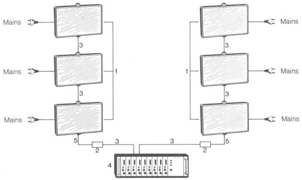
Figure 5
1 Radiator SZI 1019 A
2 Double BNC socket GZV 1019 A
3 Cable GZL 1019 A 10
4 Control transmitter SI 1019 A
5 Cable GZL 1019 A 5
Example for cabling of an infrared system
After the last radiator has been connected, you may activate the system by switching on the control transmitter. The radiators are automatically switched on by the carrier signal generated by the control transmitter and are switched off again when the signal disappears. LED ② lights to indicate that the radiator is on.
Failure indicator for diode rows
A red LED ① is assigned to each diode row and lights to indicate failure of the corresponding row. Failure of one row has no major effect on the transmission quality. The quality is reduced noticeably only if more than 3 diode rows fail. Wherever possible, this condition should be avoided, and the radiator should be repaired as soon as one row fails.
General information
In mono mode, the radiated power of one SZI 1019 A is sufficient for a room with an area of 286m^2 . This, divided by the number of diodes, results in 2m^2 per diode. If the SZI 1019 A is used in multi-channel systems, the total radiated power is divided uniformly between all channels used, i.e. the range of the radiator is dependent on the number of channels. If, for example, 4 channels are transmitted, the radiated power of an SZI 1019 A is reduced to one quarter for each channel, and the radiator then only covers an area of 75m^2 . In order to compensate for this loss, the number of radiators must be increased accordingly. The following formula can be used for determining the number of radiators required:
$$ \text {N u m b e r o f r a d i a t o r s} = \frac {\left(\text {f l o o r a r e a i n} \mathrm {m} ^ {2}\right) \times \text {n u m b e r o f c h a n n e l s}}{2 8 6} $$
This figure is only approximate and applies in rooms with bright ceilings and walls and little extra
neous light. The value (^2 covered) can be multiplied by 1.5 if the radiation is directional. For rooms with alcoves, dark walls and a high level of extraneous light, the number of radiators should be increased by a factor of 1.5.
Technical Data
| Frequency range | 30 kHz-600 kHz |
| Number of radiator diodes | 143 |
| Average radiated power | 2.3 W |
| Wave length of radiated infrared light | approx. 950 nm |
| Input impedance | approx. 5 kΩ |
| RF input voltage | 30 mV - 3 V |
| Switching threshold for automatic power on | 30 mV |
| Input/output | BNC sockets |
| Supply voltage (can be converted internally) | 115/220 V + 20% - 15% 50-60 Hz |
| Current consumption | |
| Stand by mode (220/115 V) | approx. 15 mA/18 mA |
| 220 V supply voltage | approx. 150 mA |
| 115 V supply voltage | approx. 380 mA |
| Fuse | |
| 220 V | 0.63 A |
| 115 V | 1 A |
| Dimensions in mm | 330 x 230 x 90 |
| Weight | approx. 2.2 kg |
| Delivery includes | 1 radiator, 1 mains cord (5 m). |
We reserve the right to alter specification in particular, with regard to technical improvements.
Accessories
GZL 1019 A1, GZL 1019 A5, GZL 1019 A10 (Art.-No. 2324/2325/2326)
Coaxial cable for connecting the SZI 1019 A to control transmitter SI 1019 A or SI 1013. Length: GZL 1019 A1:1 m; GZL 1019 A5:5 m; GZL 1019 A10:10 m. Connector: BNC-plug - BNC-plug.
GZV 1019 A (Art-No.2368) BNC-double socket for connection of the cable GZL 1019 A1, GZL 1019 A5, GZL 1019 A10.
SZA 1060 (Art.-No. 02829) Terminal resistance 50
GZG 1019 A (Art-No. 2341) Ball joint for mounting the SZI 1019 A to floor stands, adapter bars and ceiling mountings.
GZG 1019 (Art-No. 1642)
Celing mounting for SZI 1019 A.
MZS 1019 (Art.-No. 2340)
Adapter bar for mounting two radiators onto floor stands or ceiling mountings equipped with 3/8 -thread. Length: 41 cm.
Introduction
MZS 1019 (No. ref. 2340)