
OneLINK HDMI - Audio/video extender Vaddio - Free user manual and instructions
Find the device manual for free OneLINK HDMI Vaddio in PDF.


| Product Type | Audio/video extender |
| Brand | Vaddio |
| Model | OneLINK HDMI |
| Dimensions (W x D x H) | Approx. 4.33 x 2.36 x 0.98 in (110 x 60 x 25 mm) |
| Weight | Approx. 4.2 oz (120 g) |
| Power Supply | 5V DC via USB or HDMI stream (PoC) |
| Power Consumption | Max 2.5 W |
| HDMI Version | HDMI 1.4 with 3D support |
| Maximum Resolution | 1080p at 60 Hz |
| Supported Audio | PCM 2.0, Dolby Digital, DTS |
| Transmission Distance | Up to 330 ft (100 m) via Cat5e/6 |
| Input Interface | 1x HDMI (Type A female) |
| Output Interface | 1x RJ45 (female) |
| Operating Temperature | 32°F to 104°F (0°C to 40°C) |
| Storage Temperature | -4°F to 140°F (-20°C to 60°C) |
| Humidity | 20% to 80% (non-condensing) |
| LED Indicators | Power, Signal, Link |
| Compliance | FCC, CE, RoHS |
| Maintenance | Clean with a dry, soft cloth. Avoid liquids. |
| Safety | Use only with supplied power supply. Do not expose to moisture. |
| Spare Parts & Repairability | No user-serviceable parts. Contact Vaddio support for repairs. |
| General Information | Extends HDMI signals over long distances using standard network cabling. |
Frequently Asked Questions - OneLINK HDMI Vaddio
User questions about OneLINK HDMI Vaddio
0 question about this device. Answer the ones you know or ask your own.
Ask a new question about this device
Download the instructions for your Audio/video extender in PDF format for free! Find your manual OneLINK HDMI - Vaddio and take your electronic device back in hand. On this page are published all the documents necessary for the use of your device. OneLINK HDMI by Vaddio.
USER MANUAL OneLINK HDMI Vaddio
Installation Guide for the
OneLINK HDMI
Camera Extension
Document 411-0019-31 Rev. C
November 2019
Contents
Overview .1.
What's in this Guide..2....
Features .2
Unpacking the OneLINK HDMI Camera Extension 3.
OneLINK HDMI for HDBaseT Cameras 3
OneLINK HDMI For HDBaseT Cameras Used with...Codecs..3....
OneLINK HDMI for HDMI Cameras 4
OneLINK HDMI for HDMI Cameras Used with...Codecs.5
A Quick Look at the OneLINK.Device.7
Front Panel of the Receiver.... 7
Connector Panel of the Receiver.... 7
Connector Panel of the EZCamera Interface Module...(EZIM)...8.....
Installing the OneLINK Device 9
Don't Void Your Warranty! 9
Cabling Notes 9
RS-232 Connector Pin-Outs 10
IR Forwarding Connector Pin-Out 10
Mounting the OneLINK Device.... 11
About Installations Using the Half-Recessed Ceiling Mount 11
Visual Conventions for Connection Diagrams 11
Connections for HDBaseT Cameras.... 11
Kits and Systems for HDBaseT Cameras 12
Connecting a Vaddio HDBaseT Camera 12
Connections for HDBaseT Cameras Used with Codecs 13
Kits for HDBaseT Cameras Used with Codecs 13
Connecting a Vaddio HDBaseT Camera and Polycom Codec 14
Connecting a Vaddio HDBaseT Camera and Cisco Codec 17
Connections for HDMI Cameras 20
Kits for HDMI Cameras.... 20
Connecting a RoboSHOT HDMI Camera 21
Connecting a Polycom EagleEye IV Camera..22....
Connecting a Cisco Camera 23
Connecting a Sony or Panasonic HDMI Camera 25
Connections for HDMI Cameras Used with Codecs 27
Kits for HDMI Cameras Used with Codecs 27
Connecting a RoboSHOT HDMI Camera and Polycom Codec 28
Connecting a Polycom EagleEye IV Camera and Polycom Codec 31
Connecting a RoboSHOT HDMI Camera and Cisco Codec 34
Connecting a Cisco Camera and Codec 38
Powering Up the Equipment 43
Next Steps 43
Operation, Storage, and Care 43
Compliance Statements and Declarations of Conformity 44
FCC Part 15 Compliance 44
ICES-003 Compliance 44
European Compliance 45
Warranty Information...46....
Index 47
Overview
This guide covers the OneLINK™ HDMI camera extension, which is available in the following kit configurations for use with Vaddio or third-party cameras, with or without third-party codecs.
■ 999-1105-043/143/943, OneLINK HDMI for Vaddio HDBaseT™ cameras
■ 999-9520-000/001/009, OneLINK HDMI camera extension for Polycom EagleEye IV cameras with Polycom codecs
■ 999-9530-000/001/009, OneLINK HDMI camera extension for Sony and Panasonic cameras
■ 999-9540-000/001/009, OneLINK HDMI camera extension for RoboSHOT HDMI cameras with Polycom codecs (discontinued)
■ 999-9545-000/001/009, OneLINK HDMI camera extension for Vaddio HDBaseT cameras with Polycom codecs
■ 999-9560-000/001/009, OneLINK HDMI camera extension for Cisco cameras with Cisco codecs
■ 999-9570-000/001/009, OneLINK HDMI camera extension for RoboSHOT HDMI cameras with Cisco codecs (camera has been discontinued)
■ 999-9575-000/001/009, OneLINK HDMI camera extension for Vaddio HDBaseT cameras with Cisco codecs
■ 999-9590-000/001, OneLINK HDMI camera extension for RoboSHOT HDMI cameras (camera has been discontinued)
Part number suffixes indicate power cord set types. Those ending in -000 include cord sets for America; -001 kits include cord sets for use in Europe and the UK; -009 kits include cord sets Australia and New Zealand.
The OneLINK HDMI camera extension is also available as a component of several Vaddio camera systems.
Note
The kits for RoboSHOT HDMI cameras are still available, although the RoboSHOT 12 HDMI and RoboSHOT 30 HDMI cameras have been discontinued. OneLINK devices are not compatible with RoboSHOT 12E HDMI and RoboSHOT 30E HDMI cameras.

If the camera extension is sold for use with an HDMI camera, it is shipped with a OneLINK Interface Module (EZIM).
What's in this Guide
This guide provides information about:
■ Unpacking the OneLINK device
■ The OneLINK device's physical features
■ Installing the OneLINK device
■ Initial power-on
■ Warranty and compliance/conformity information
Complete product information is available in the Complete Manual for the OneLINK HDMI Camera Extension.
Features
■ Simple, fast, clutter-free camera installation – power, control, video, and network connectivity over a single cable
■ Extends installation distance for HDMI and HDBaseT™ cameras up to 100 m (328 ft.) using Cat-6 cable; 230 ft (70 m) using Cat-5e
■ Passes uncompressed HDMideo up to 2160p/29.97
■ Bidirectional control via Ethernet and RS-232
■ Compatible with Vaddio HDBaseT cameras - no EZCamera Interface Module (EZIM) needed
■ Compatible with legacy RoboSHOT HDMI and other HDMI cameras
■ Available in system configurations with Vaddio cameras
■ Kits available for use with Polycom and Cisco codecs and HDMI cameras
Note
OneLINK products are not compatible with RoboSHOT 12E HDMI or RoboSHOT 30E HDMI camera
Unpacking the OneLINK HDMI Camera Extension
Make sure you received all the items you expected. Here are the packing lists for the OneLINK Every OneLINK device ships with a power supply and at least one AC cord set. The last three kit part number contain the regional code that specifies which cord set(s). For most OneLINK kits numbers follow this convention:
■ Kits with part numbers ending in -000 include one AC cord set for North America.
■ Kits with part numbers ending in -001 include two AC cord sets, one for Europe and one for the UK.
■ Kits with part numbers ending in -009 include one AC cord set for Australia and New Zealand.
Exceptions are noted case by case in the following packing lists.
OneLINK HDMI for HDBaseT Cameras
OneLINK HDMI Camera Extension for Vaddio HDBaseT Cameras, 999-1105-043/143/943
Camera not included.
■ OneLINK HDMI Receiver, 998-1105-043
■ Power supply, 48 VDC/1.36 A, with AC cord set(s)
- Kit 999-1105-043 includes one AC cord set for North America.
- Kit 999-1105-143 includes two AC cord sets, one for Europe and one for the UK.
- Kit 999-1105-943 includes one AC cord set for Australia and New Zealand.
■ EZCamera RS-232 control adapter (998-1001-232)
■ Quick-Start Guide 411-0019-01

OneLINK HDMI For HDBaseT Cameras Used with Codecs
OneLINK HDMI for Vaddio HDBaseT Cameras with Polycom Codecs, 999-9545-000/001/009
Camera and codec not included.
■ OneLINK HDMI Receiver
■ Power supply, 48 VDC/1.36 A, with AC cord set(s)
■ 3-position Euro-style connector, 5 mm
■ Fan-out cable, codec side, 2 ft. (0.6 m)
■ EZCamera RS-232 control adapter 998-1001-232
■ Quick-Start Guide 411-0019-01

OneLINK HDMI for Vaddio HDBaseT Cameras with Cisco Codecs, 999-9575-000/001/009
Camera and codec not included.
Note
If connecting to a Cisco SX20 codec, you will need to provide
a Cisco split cable, Cisco part number CAB-PHD4XS
SPLIT.

■ OneLINK HDMI Receiver
■ Power supply, 48 VDC/1.36 A, with AC cord set(s)
■ HDMI cable, 3 ft. (0.9 m)
■ Custom-pinout Cat-5e cable for Cisco, 3 ft. (0.9 m)
■ EZCamera RS-232 control adapter 998-1002-232
■ Cat-5e patch cable, 3 ft. (0.9 m)
■ Quick-Start Guide 411-0019-01
OneLINK HDMI for HDMI Cameras
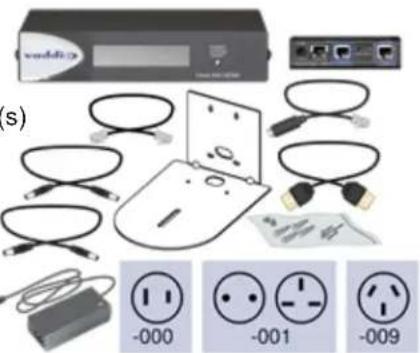
OneLINK HDMI for RoboSHOT HDMI Cameras, 999-9590-000/001/009
Camera not included.
■ OneLINK HDMI Receiver
■ OneLINK EZCamera Interface Module (EZIM) with mounting screws
■ Power supply, 48 VDC/1.36 A, with AC cord set(s)
■ Power cable EIAJ-04 to EIAJ-04, 1 ft. (0.3 m)
■ Cat-5e patch cable, 1 ft. (0.3 m), qty. 2
■ HDMI cable, 1 ft. (0.3 m)
■ EZCamera RS-232 control adapter
■ Quick-Start Guide 411-0019-02

Note
The RoboSHOT 12 HDMI and RoboSHOT 30 HDMI cameras have been discontinued. This kit is compatible with RoboSHOT 12E HDMI and RoboSHOT 30E HDMI cameras.
OneLINK HDMI for Sony and Panasonic Cameras, 999-9530-000/001/009
Camera not included.
■ OneLINK HDMI Receiver
■ OneLINK EZCamera Interface Module (EZIM)
■ Power supply, 48 VDC/1.36 A, with AC cord set(s)
■ Power cable EIAJ-04 to EIAJ-04, 1 ft. (0.3 m)
■ Power cable EIAJ-04 to 3x6.3mm, 1 ft (0.3 m)
■ Wall mount with mounting hardware for Sony and Panasonic cameras
■ HDMI cable, 1 ft. (0.3 m)
■ RJ-45 to 8-pin mini-DIN cable, 1 ft. (0.3 m)
■ Cat-5e patch cable, 1 ft. (0.3 m)
■ Quick-Start Guide 411-0019-02
OneLINK HDMI for HDMI Cameras Used with Codecs
OneLINK HDMI for Polycom Cameras with Polycom Codecs, 999-9520-000/001/009
Camera and codec not included.
■ OneLINK HDMI Receiver
■ OneLINK EZCamera Interface Module (EZIM)
■ Power supply, 48 VDC/1.36 A, with AC cord set(s)
■ Wall mount with mounting hardware for Polycom codec and camera
■ Fan-out cable, EZIM side, 1 ft. (0.3 m)
■ Fan-out cable, codec side, 2 ft. (0.6 m)
■ 3-position Euro-style connector, 5 mm
■ EZCamera RS-232 control adapter 998-1001-232
■ Quick-Start Guide

OneLINK HDMI for RoboSHOT HDMI with Polycom
Codecs, 999-9540-000/001/009
Camera and codec not included.
■ OneLINK HDMI Receiver
■ OneLINK EZCamera Interface Module (EZIM), with mounting screws
■ Power supply, 48 VDC/1.36 A, with AC cord set(s)
■ Fan-out cable, codec side, 2 ft. (0.6 m)
■ 3-position Euro-style connector, 5 mm
■ HDMI cable, 1 ft. (0.3 m)
■ Power cable EIAJ-04 to EIAJ-04, 1 ft. (0.3 m)
■ Cat-5e patch cable, 1 ft. (0.3 m), qty. 2
■ Quick-Start Guide 411-0019-02

Note
The RoboSHOT 12 HDMI and RoboSHOT 30 HDMI cameras have been discontinued. This kit is compatible with RoboSHOT 12E HDMI and RoboSHOT 30E HDMI cameras.
OneLINK HDMI for Cisco Cameras with Cisco Codecs, 999-9560-000/001/009
Camera and codec not included.
Note
If connecting to a Cisco SX20 codec, you will need to provide a Cisco split cable, Cisco part number CAB-PHD4XS2 SPLIT. This cable is also required when connecting to a Cisco Precision 40 or Precision HD 1080p2.5x camera; you will need two of them if connecting one of these cameras and an SX20 codec.

■ OneLINK HDMI Receiver
■ OneLINK EZCamera Interface Module (EZIM)
■ Power supply, 48 VDC/1.36 A, with AC cord set(s)
■ Power cable EIAJ-04 to 5.5x2.1 mm, 1 ft. (0.3 m)
■ Wall mount with mounting hardware for Cisco codec and camera
■ HDMI cable, 3. ft. (0.9 m)
■ HDMI cable, 1 ft. (0.3 m)
■ Custom-pinout Cat-5e cable for Cisco, 3 ft. (0.9 m)
■ Custom-pinout Cat-5e cable for Cisco, 1 ft. (0.3 m)
■ Cat-5e patch cable, 1 ft. (0.3 m)
■ Cat-5e patch cable, 3 ft. (0.9 m)
■ EZCamera RS-232 control adapter 998-1002-232
■ Quick-Start Guide 411-0019-02
OneLINK HDMI for RoboSHOT HDMI with Cisco Codecs, 999-9570-000
Camera and codec not included.
Note
If connecting to a Cisco SX20 codec, you will need to provide a Cisco split cable, Cisco part number CAB-PHD4XS2 SPLIT.
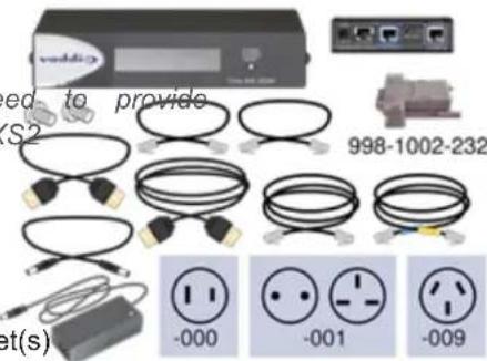
■ OneLINK HDMI Receiver
■ OneLINK EZCamera Interface Module (EZIM) with mounting screws
■ Power supply, 48 VDC/1.36 A, with AC cord set(s)
■ Power cable EIAJ-04 to EIAJ-04, 1 ft. (0.3 m)
■ HDMI cable, 3 ft. (0.9 m)
■ HDMI cable, 1 ft. (0.3 m)
■ Custom-pinout Cat-5e cable for Cisco, 3 ft. (0.9 m)
■ Cat-5e patch cable, 1 ft. (0.3 m), qty. 2
■ Cat-5e patch cable, 3 ft. (0.9 m)
■ EZCamera RS-232 control adapter 998-1002-232
■ Quick-Start Guide 411-0019-02
Note
The RoboSHOT 12 HDMI and RoboSHOT 30 HDMI cameras have been discontinued. This kit is compatible with RoboSHOT 12E HDMI and RoboSHOT 30E HDMI cameras.
A Quick Look at the OneLINK Device
This section covers the physical features of the OneLINK HDMI camera extension.
All OneLINK kits include a receiver, which is typically co-located with other equipment, up to 328 away from the camera. OneLINK kits for use with HDMI cameras also include an EZCamera Inte Module (EZIM) HDBaseT converter, which is mounted adjacent to the camera.
Front Panel of the Receiver

- Data Display – Shows the IP and MAC addresses for the OneLINK HDMI camera extension (not the camera). Use the IP address to access the OneLINK HDMI web interface.
■ Power System Reset button (illuminated red) – reboots the OneLINK Bridge without affecting the connected camera.
Connector Panel of the Receiver
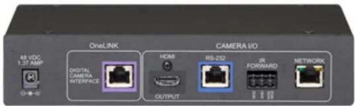
From the left:
■ Power input jack – Use the supplied 48VDC, 1.36A power supply.
- OneLINK interface port – Connect a Cat-5e (or better) cable to the EZIM, or to the camera if your OneLINK kit or system did not include an EZIM. This bidirectional connection carries video, netw connectivity including H.264 IP streaming from the camera (if available), RS-232 control, and 12 power.
■ HDMI output - HDMI output to a connected display.
■ RS-232 port - Connect to a camera controller.
- IR forwarding port – To forward IR signals from the camera, if available. Modulated and non-modulated outputs provided.
■ Network port – H.264 IP streaming (if available from the camera), web interface access, and third-party IP control via Telnet API.
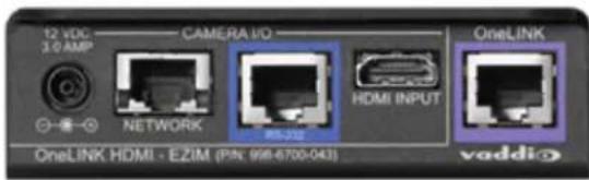
Connector Panel of the EZCamera Interface Module (EZIM)
If the OneLINK device is used with an HDMI camera, the EZIM is required.

From the left:
■ Power output jack – Supplies power to the camera. The kit you purchased includes the appropriate cable to connect your camera's power input to this jack.
■ Network port – Provides network connectivity to the camera for H.264 IP streaming (if available from the camera), web interface access, and third-party control via Telnet API. Connect to the came network port.
■ RS-232 port – Provides RS-232 connectivity to the camera, for third-party control. The kit you purchased may include a cable and/or an RS-232 adapter to connect to the camera's RS-232
■ HDMI input – Receives HDMI video from the camera. Connect to the camera's HDMI output.
- OneLINK port – Single-cable connection to the OneLINK receiver. This bidirectional connection carries all video, power, and control.
Installing the OneLINK Device
This section covers:
■ Things to know before you start the installation
■ Basic connection examples
Download dimensional drawings, quick-start guides, and other information from the appropriate OneLIN kit page on legrandav.com.
Don't Void Your Warranty!
Caution
Use only the power supply included with this product. Using a different one will void the warrant could create unsafe operating conditions or damage the product.
Do not connect the OneLINK power supply to a Vaddio camera. It does not provide the correct Vaddio cameras, and will damage the camera and void the camera's warranty.
This product is for indoor use only. Do not install it outdoors or in a humid environment. Do not come into contact with any liquid. Do not install or operate this product if it has been dropped, exposed to liquids. If any of these things happen, return it to Vaddio for safety and functional
Note
Disassembling this product will void the warranty.
Cabling Notes
Cable distance between the EZIM (or the camera, if no EZIM is used) and the OneLINK device maximum of 328 feet (100 m) using Cat-6 or Cat-7 cable, or 230 feet (70 m) using Cat-5e cat Cat-6 or Cat-7 cabling allows longer maximum cabling distance, and may provide better performance noisier RF or EMF environments. We recommend shielded cabling if the cables will be coiled, run with other cables, or routed near sources of electromagnetic interference such as power lines or light fixtures. When in doubt, use shielded Cat-6 cable.
Caution
When making cables for Vaddio products, do not use pass-through RJ-45 connectors. If they are crimped incorrectly, they can damage the connectors on the product cause intermittent connections, and degrade signal quality. Physical damage to the connectors will void your warranty.

Intact
Contact fingers will make re contact with the cable conn

Damaged
Some contact fingers are bent and will NOT make reliable contact with the cable connector
We recommend using high-quality connectors and a high-quality crimping tool.

Pro Tip
To prevent tragic mishaps, label both ends of every cable.
RS-232 Connector Pin-Outs
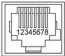
OneLINK Receiver - RS-232 Control Port
- Unused
- Unused
- Unused
- Unused
- Unused
- GND - green
- RX (from TX of controller) - brown/white
- TX (to RX of controller) - brown
OneLINK EZIM - RS-232 Control Port
- Unused
- Unused
- Unused
- IR GND
- IR (non-mod)
- GND - green
- TX (to RX of camera) - brown/white
- RX (from TX of camera) - brown
Note
Vaddio recommends adhering to the 568B cabling standard for Cat-5 cabling.
IR Forwarding Connector Pin-Out
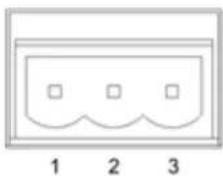
natural_image
Simple diagram with three squares inside a rounded rectangle, labeled 1, 2, and 3 below (no text or symbols within the diagram itself)- Modulated IR
- Common Ground
- Non-modulated IR
Mounting the OneLINK Device
If you are installing the OneLINK device with a OneLINK EZIM, mount the EZIM with or near 1 The Thin Profile Wall Mount for the camera may include mounting holes to attach the EZIM to of the mount using two 6-32 screws. Connect all required cables during camera installation.
Rack and under-table mounting kits are available for the receiver. Follow the mounting instructions with the kit.
About Installations Using the Half-Recessed Ceiling Mount
If the connected camera is mounted in Vaddio's Half-Recessed Ceiling Mount, the camera's IR rec unable to receive signals from the remote. The mount has an IR receiver that can forward comi camera; this must be powered separately using Power Extension Module 999-1005-021. Cameras po by OneLINK devices cannot supply power to the mount's IR receiver.
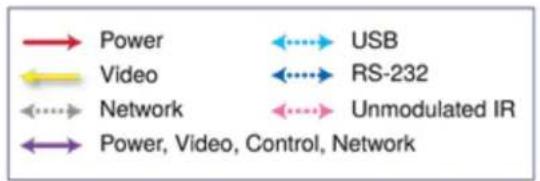
Visual Conventions for Connection Diagrams
The following sections provide representative connection diagrams for the various OneLINK kit and configurations available. All diagrams in this guide use these visual conventions for connection type
Connections for HDBaseT Cameras
In this configuration, the OneLINK HDMI extends network connectivity, power, and control to an HI camera, and brings HDMI video from the camera to a display. The camera can optionally be cc camera controller on an RS-232 serial connection to the OneLINK HDMI or over the network, dep the controller.
If an IP stream is available from the camera, the OneLINK device passes it to the network. IP resolutions up to 2160p/30 are supported. HDMI output resolution and streaming parameters (including resolution) are configured on the camera, not the OneLINK device.

flowchart
graph TD
    A["HDBT Camera"] --> B["OneLINK HDMI"]
    C["Controller"] <--> B
    D["Display"] <--> B
    E["Laptop"] --> F["Network"]
    B --> G["Data Flow"]
    B --> H["Data Flow"]
The controller is optional.
Kits and Systems for HDBaseT Cameras
This block diagram applies to:
■ OneLINK HDMI for HDBaseT Cameras, 999-1105-043/143/943 – compatible with all Vaddio HDBaseT cameras.
■ RoboSHOT 12 HDBT OneLINK HDMI System, 999-9960-100/101
■ RoboSHOT 30 HDBT OneLINK HDMI System, 999-9963-100/100W/101/101W
■ RoboSHOT 20 UHD OneLINK HDMI System, 999-9950-100/101/109
■ DocCAM 20 HDBT OneLINK HDMI System, 999-9968-200/201/209
■ Future systems consisting of a Vaddio HDBaseT camera and a OneLINK HDMI receiver
Connecting a Vaddio HDBaseT Camera
999-1105-043/143/943
This diagram is also valid for the following systems:
■ RoboSHOT 12 HDBT OneLINK HDMI System, 999-9960-100/101
■ RoboSHOT 30 HDBT OneLINK HDMI System, 999-9963-100/100W/101/101W
■ DocCAM 20 HDBT OneLINK HDMI System, 999-9968-200/201/209
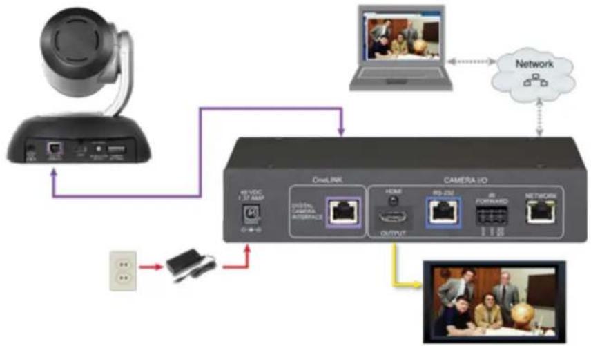
In this diagram, the OneLINK HDMI extends network connectivity, power, and control to a RoboSHOT HDBT camera, and brings camera video to the connected HDMI display. The OneLINK passes the camera's IP stream (if available) to the network.
Items in this diagram:
■ OneLINK HDMI receiver
■ RoboSHOT 12 HDBT camera (not included in kit 999-1105-043/143/943)
■ HDMI display and HDMI cable (not included)
■ Laptop receiving the camera's IP stream (not included)
■ Cat-5e cables for OneLINK and network connections (not included)
RoboSHOT HDBT Camera
Other Vaddio HDBaseT cameras connect in the same way.
flowchart
graph TD
    A["OneLink"] -->|48 VDC 1.37 AMP| B["OneLink Interface"]
    B --> C["Output"]
    D["CAMERA I/O"] --> E["Output"]
    F["Laptop"] --> G["Network"]
    G --> H["Video Device"]
    style A fill:#f9f,stroke:#333
    style D fill:#ccf,stroke:#333
    style F fill:#cfc,stroke:#333
Connections for HDBaseT Cameras Used with Codecs
In this configuration, the OneLINK HDMI extends network connectivity, power, and control to an HI camera, and brings HDMI video from the camera to the codec. The codec may be connected to OneLINK device directly via RS-232, or they may communicate over the IP network, depending on codec.
If an IP stream is available from the camera, the OneLINK device passes it to the network. IP resolutions up to 2160p/30 are supported. HDMI output resolution and streaming parameters (including resolution) are configured on the camera, not the OneLINK device.

flowchart
graph TD
    A["HDBT Camera"] --> B["OneLINK HDMI"]
    B --> C["Display"]
    C --> D["Cdec"]
    D --> E["Network"]
    E --> F["Laptop"]
    B --> G["Mobile Device"]
    style A fill:#fff,stroke:#000
    style F fill:#fff,stroke:#000
    style B fill:#ccc,stroke:#000
    style C fill:#fff,stroke:#000
    style D fill:#fff,stroke:#000
    style E fill:#ccc,stroke:#000
    style F fill:#fff,stroke:#000
    style G fill:#fff,stroke:#000
Kits for HDBaseT Cameras Used with Codecs
This block diagram applies to:
■ OneLINK HDMI for Vaddio HDBaseT Cameras with Polycom Codecs, 999-9545-000/001/009 – compatible with all Vaddio HDBT cameras and with Polycom RealPresence Group Series codecs.
■ OneLINK HDMI for Vaddio HDBaseT Cameras with Cisco Codecs, 999-9575-000/001/009 – compatible with all Vaddio HDBT cameras and with Cisco C20, C40, C60, SX20, and SX80 c
Connecting a Vaddio HDBaseT Camera and Polycom Codec
999-9545-000/001/009
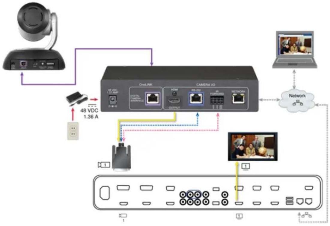
In these diagrams, the OneLINK device extends network connectivity, power, and control to a Rob HDBT camera, and connects it to a Polycom RealPresence Group Series codec. The OneLINKdevi passes the camera's IP stream (if available) to the network. The codec provides HDMI video to connected display.
Other Vaddio HDBaseT cameras would be connected in exactly the same way.
Items in these diagrams:
■ OneLINK HDMI receiver
■ Power supply with AC cord set
■ Codec-side fan-out cable, bare wires terminated with 3-position, 5mm Euro-style connector
■ RoboSHOT 12 HDBT camera (not included)
■ Polycom RealPresence Group Series codec (not included)
■ HDMI display and HDMI cable (not included)
■ Laptop receiving the camera's IP stream (not included)
■ Cat-5e cables for OneLINK and network connections (not included)
RoboSHOT HDBT Camera and Polycom RealPresence Group 310 Codec
The Group 500 codec looks very similar and connects in the same way.
Other Vaddio HDBaseT cameras connect in the same way.

flowchart
graph TD
    A["Camera"] -->|48 VDC 1.36 A| B["OneLink"]
    A --> C["CAMERA I/O"]
    B --> D["O2VDC 1.36 A"]
    B --> E["VIDEO CAMERA INTERFACE"]
    B --> F["OUTPUT"]
    B --> G["RIS-250"]
    B --> H["RIS-FORMS"]
    B --> I["NETWORK"]
    C --> J["Network"]
    J --> K["Laptop"]
    K --> L["Cloud"]
    L --> M["Video Device"]
    M --> N["Monitor"]
    N --> O["Display"]
    O --> P["User Interface"]
RoboSHOT HDBT Camera and Polycom RealPresence Group 700 Codec Other Vaddio HDBaseT cameras connect in the same way.
flowchart
graph TD
    A["User"] --> B["OneLink"]
    B --> C["CAMERA I/O"]
    C --> D["Network"]
    D --> E["Laptop"]
    B --> F["48 VDC 1.36A"]
    F --> G["48 VDC 1.37 Mbps"]
    G --> H["Output"]
    H --> I["Device 1"]
    I --> J["Device 2"]
    J --> K["Device 3"]
    K --> L["Device 4"]
    L --> M["Device 5"]
    M --> N["Device 6"]
    N --> O["Device 7"]
    O --> P["Device 8"]
    P --> Q["Device 9"]
    Q --> R["Device 10"]
    R --> S["Device 11"]
    S --> T["Device 12"]
    T --> U["Device 13"]
    U --> V["Device 14"]
    V --> W["Device 15"]
    W --> X["Device 16"]
    X --> Y["Device 17"]
    Y --> Z["Device 18"]
    Z --> AA["Device 19"]
    AA --> AB["Device 20"]
    AB --> AC["Device 21"]
    AC --> AD["Device 22"]
    AD --> AE["Device 23"]
    AE --> AF["Device 24"]
    AF --> AG["Device 25"]
Hardware Note: IR Forwarding
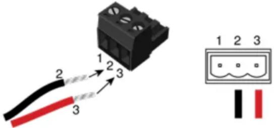
Use the supplied 3-position Euro-style connector to terminate the two unterminated wires of the cc fan-out cable as follows:
■ Black wire: Center position (pin 2)
■ Red wire: Right position (pin 3)
Connect this part of the fan-out cable to the IR FORWARD connector on the OneLINK HDMI re
Note
Some fan-out cables have a black/white wire instead of a red one. Wiring is the same - black black/white to pin 3.
Some older fan-out cables have the wires reversed. This will not damage the equipment. If IR f does not work when you terminate the cable per these instructions, remove power from the OneL device, disconnect the fan-out cable, and re-terminate the wires with red (or black/white) to pin 2 to pin 3. Then reconnect the cable and power up the OneLINK device again.
Hardware Note: Connection and Configuration Changes
After connecting or configuring the equipment, reboot the OneLINK device, camera, and codec. Not rebooting the OneLINK device does not affect the camera and codec; they must be rebooted sep
Connecting a Vaddio HDBaseT Camera and Cisco Codec
999-9575-000/001/009
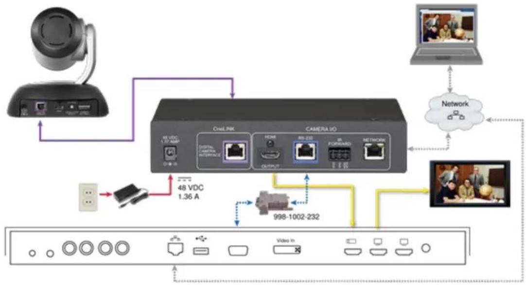
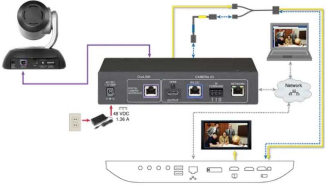
In these diagrams, the OneLINK device extends network connectivity, power, and control to a Rob 12 HDBT camera, and connects it to a Cisco codec. The OneLINK device passes the camera's IF (if available) to the network. The codec provides HDMI video to the connected display.
Other Vaddio HDBaseT cameras would be connected in exactly the same way.
Items in these diagrams:
■ OneLINK HDMI receiver
■ Power supply and AC cord set
■ Cisco split cable CAB-PHD4XS2-SPLIT(not included; required for SX20 codec)
■ Codec-side null modem cable (used with split cable on SX20 codec)
■ RoboSHOT 12 HDBT camera (not included)
■ Cisco codec (not included)
■ HDMI display and HDMI cable (not included)
■ Laptop receiving the camera's IP video stream (not included)
■ Cat-5e cables for OneLINK and network connections (not included)
■ RS-232 adapter 998-1002-232 (used with standard Cat-5 cable on C20, C60. and SX80 codecs)
RoboSHOT HDBT Camera and Cisco C20 Codec
Other Vaddio HDBaseT cameras connect in the same way.
flowchart
graph TD
    A["Camera"] -->|USB Interface 1.36 A| B["48 VDC"]
    B --> C["USB Interface"]
    C --> D["48 VDC"]
    D --> E["Video In"]
    E --> F["998-1002-232"]
    F --> G["Network"]
    G --> H["Laptop"]
    H --> I["Video"]
    I --> J["Video In"]
    J --> K["Internet"]
    K --> L["Network"]
    L --> M["48 VDC"]
    M --> N["48 VDC"]
    N --> O["Analog port"]
RoboSHOT HDBT Camera and Cisco C60 Codec
The C40 codec looks very similar and connects in the same way.
Other Vaddio HDBaseT cameras connect in the same way.

flowchart
graph TD
    A["Camera"] -->|48 VDC 1.36 A| B["OneLINK"]
    B --> C["CAMERA 10"]
    C --> D["Output"]
    D --> E["HDMI"]
    E --> F["48 VDC"]
    F --> G["OneLINK"]
    G --> H["OneLINK"]
    H --> I["Network"]
    I --> J["Camera Control"]
    J --> K["998-1002-232"]
RoboSHOT HDBT Camera and Cisco SX20 Codec
Other Vaddio HDBaseT cameras connect in the same way.
flowchart
graph TD
    A["Camera"] -->|48 VDC 1.36 A| B["Video Link"]
    B --> C["Camera ID"]
    C --> D["Output"]
    C --> E["Network"]
    E --> F["Laptop"]
    F --> G["Network"]
    G --> H["Video"]
    H --> I["Monitor"]
    I --> J["Display"]
    J --> K["User Interface"]
    K --> L["Camera ID"]
    L --> M["Output"]
    L --> N["Network"]
    N --> O["Laptop"]
    O --> P["Network"]
    P --> Q["Video"]
    Q --> R["Monitor"]
    R --> S["Display"]
Note
If connecting to a Cisco SX20 codec, you will need to provide a Cisco split cable, Cisco part PHD4XS2-SPLIT.
RoboSHOT HDBT Camera and Cisco SX80 Codec
Other Vaddio HDBaseT cameras connect in the same way.

flowchart
graph TD
    A["User"] --> B["OneLink"]
    B --> C["Digital Camera Interface"]
    B --> D["Video In"]
    B --> E["Camera Control"]
    B --> F["Network"]
    B --> G["Desktop"]
    B --> H["Network"]
    B --> I["48 VDC 1.36 A"]
    B --> J["48 VDC 1.37 AMP"]
    B --> K["48 VDC 1.37 A"]
    B --> L["48 VDC 1.37 A"]
    B --> M["48 VDC 1.37 A"]
    B --> N["48 VDC 1.37 A"]
    B --> O["48 VDC 1.37 A"]
    B --> P["48 VDC 1.37 A"]
    B --> Q["48 VDC 1.37 A"]
    B --> R["48 VDC 1.37 A"]
    B --> S["48 VDC 1.37 A"]
    B --> T["48 VDC 1.37 A"]
    B --> U["48 VDC 1.37 A"]
    B --> V["48 VDC 1.37 A"]
    B --> W["48 VDC 1.37 A"]
    B --> X["48 VDC 1.37 A"]
    B --> Y["48 VDC 1.37 A"]
    B --> Z["48 VDC 1.37 A"]
    B --> AA["48 VDC 1.37 A"]
    B --> AB["48 VDC 1.37 A"]
    B --> AC["48 VDC 1.37 A"]
    B --> AD["48 VDC 1.37 A"]
    B --> AE["48 VDC 1.37 A"]
    B --> AF["48 VDC 1.37 A"]
    B --> AG["48 VDC 1.37 A"]
    B --> AH["48 VDC 1.37 A"]
    B --> AI["48 VDC 1.37 A"]
    B --> AJ["48 VDC 1.37 A"]
    B --> AK["48 VDC 1.37 A"]
    B --> AL["48 VDC 1.37 A"]
    B --> AM["48 VDC 1.37 A"]
    B --> AN["48 VDC 1.37 A"]
    B --> AO["48 VDC 1.37 A"]
    B --> AP["48 VDC 1.37 A"]
    B --> AQ["48 VDC 1.37 A"]
    B --> AR["48 VDC 1.37 A"]
    B --> AS["48 VDC 1.37 A"]
    B --> AT["48 VDC 1.37 A"]
    B --> AU["48 VDC 1.37 A"]
    B --> AV["48 VDC 1.37 A"]
    B --> AW["48 VDC 1.37 A"]
    B --> AX["48 VDC 1.37 A"]
    B --> AY["48 VDC 1.37 A"]
    B --> AZ["48 VDC 1.37 A"]
    B --> BA["48 VDC 1.37 A"]
    B --> BB["48 VDC 1.37 A"]
    B --> BC["48 VDC 1.37 A"]
    B --> BD["48 VDC 1.37 A"]
    B --> BE["48 VDC 1.37 A"]
    B --> BF["48 VDC 1.37 A"]
    B --> BG["48 VDC 1.37 A"]
    B --> BH["48 VDC 1.37 A"]
    B --> BI["48 VDC 1.37 A"]
    B --> BJ["48 VDC 1.37 A"]
    B --> BK["48 VDC 1.37 A"]
    B --> BL["48 VDC 1.37 A"]
    B --> BM["48 VDC 1.37 A"]
    B --> BN["48 VDC 1.37 A"]
    B --> BO["48 VDC 1.37 A"]
    B --> BP["48 VDC 1.37 A"]
    B --> BQ["48 VDC 1.37 A"]
    B --> BR["48 VDC 1.37 A"]
    B --> BS["48 VDC 1.37 A"]
    B --> BT["48 VDC 1.37 A"]
    B --> BU["48 VDC 1.37 A"]
    B --> BV["48 VDC 1.37 A"]
    B --> BW["48 VDC 1.37 A"]
    B --> BX["48 VDC 1.37 A"]
    B --> BY["48 VDC 1.37 A"]
    B --> BZ["48 VDC 1.37 A"]
    B --> CA["48 VDC 1.37 A"]
    B --> CB["48 VDC 1.37 A"]
    B --> CC["48 VDC 1.37 A"]
    B --> CD["48 VDC 1.37 A"]
    B --> CE["48 VDC 1.37 A"]
    B --> CF["48 VDC 1.37 A"]
    B --> CG["48 VDC 1.37 A"]
    B --> CH["48 VDC 1.37 A"]
    B --> CI["48 VDC 1.37 A"]
    B --> CJ["48 VDC 1.37 A"]
    B --> CK["48 VDC 1.37 A"]
    B --> CL["48 VDC 1.37 A"]
    B --> CD
    style B fill:#f9f,stroke:#333,stroke-width:2px
    style C fill:#ccf,stroke:#333
    style D fill:#cfc,stroke:#333
    style E fill:#fcc,stroke:#333
    style F fill:#cff,stroke:#333
    style G fill:#ffc,stroke:#333
    style H fill:#cfc,stroke:#333
    style I fill:#fcc,stroke:#333
    style J fill:#cfc,stroke:#333
    style K fill:#fcc,stroke:#333
    style L fill:#cfc,stroke:#333
    style M fill:#fcc,stroke:#333
    style N fill:#cfc,stroke:#333
    style O fill:#fcc,stroke:#333
    style P fill:#cfc,stroke:#333
    style Q fill:#fcc,stroke:#333
    style R fill:#cfc,stroke:#333
    style S fill:#fcc,stroke:#333
    style T fill:#cfc,stroke:#333
    style U fill:#fcc,stroke:#333
    style V fill:#cfc,stroke:#333
    style W fill:#fcc,stroke:#333
    style X fill:#cfc,stroke:#333
    style Y fill:#fcc,stroke:#333
    style Z fill:#cfc,stroke:#333
    style AA fill:#fcc,stroke:#333
    style AB fill:#cfc,stroke:#333
    style AC fill:#fcc,stroke:#333
    style AD fill:#cfc,stroke:#333
    style AE fill:#fcc,stroke:#333
    style AF fill:#cfc,stroke:#333
    style AG fill:#fcc,stroke:#333
    style AH fill:#cfc,stroke:#333
    style AI fill:#fcc,stroke:#333
    style AJ fill:#cfc,stroke:#333
    style AK fill:#fcc,stroke:#333
    style AL fill:#cfc,stroke:#333
    style AM fill:#fcc,stroke:#333
    style AN fill:#cfc,stroke:#333
    style AO fill:#fcc,stroke:#333
    style AP fill:#cfc,stroke:#333
    style AQ fill:#fcc,stroke:#333
    style AR fill:#cfc,stroke:#333
    style AS fill:#fcc,stroke:#�255
Hardware Note: RS-232 Connections
For RS-232 connections to Cisco gear using DE-9 connectors, use the 998-1002-232 RJ-45 to DE adapter. Its wiring differs from the 998-1001-232 adapter shipped with many Vaddio products.
For RS-232 connections to Cisco gear using the Cisco split cable, use the appropriate null-modem the RJ-45 side of the split cable. Connect the null-modem cable as indicated on the cable label
Hardware Note: Connection and Configuration Changes
After connecting or configuring the equipment, reboot the OneLINK device, camera, and codec. Not rebooting the OneLINK device does not affect the camera and codec; they must be rebooted sep
Connections for HDMI Cameras
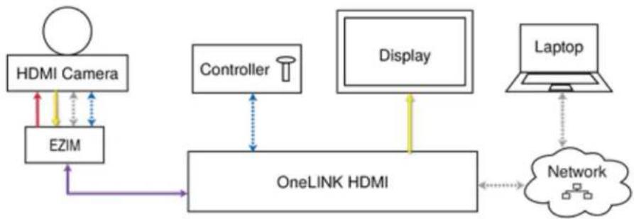
In this configuration, the OneLINK HDMI extends network connectivity, power, and control to an HI camera, and brings HDMI video from the camera to a display. The camera can optionally be cc camera controller on an RS-232 serial connection to the OneLINK HDMI or over the network, dep the controller.
If an IP stream is available from the camera, the OneLINK device passes it to the network. IP resolutions up to 2160p/30 are supported. HDMI output resolution and streaming parameters (including resolution) are configured on the camera, not the OneLINK device.
flowchart
graph TD
    A["HDMI Camera"] -->|red arrow| B["EZIM"]
    B --> C["OneLINK HDMI"]
    D["Controller"] <--> C
    E["Display"] --> C
    F["Laptop"] --> G["Network"]
    G --> C
    C --> H["Output"]
Kits for HDMI Cameras
This block diagram applies to:
■ OneLINK HDMI camera extension for Polycom cameras with Polycom Codecs, 999-9520-000/001/009, when used without a codec - compatible with Polycom EagleEye IV camera.
■ OneLINK HDMI camera extension for Sony and Panasonic Cameras, 999-9530-000/001/009 - compatible with Panasonic HE-series, Sony EVI-D series, and Sony BRC-H series cameras.
■ OneLINK HDMI camera extension for Cisco Cameras with Cisco Codecs, 999-9660-000/001/009, when used without a codec – compatible with Cisco Precision series cameras.
■ OneLINK HDMI camera extension for RoboSHOT HDMICameras, 999-9590-000/001/009 (camera has been discontinued)
Connecting a RoboSHOT HDMI Camera
999-9590-000/001/009
In this diagram, the OneLINK device extends network connectivity, power, and control to a RoboSI HDMI camera, and brings camera video to the connected HDMI display.
Items in this diagram:
■ OneLINK HDMI receiver and OneLINK EZIM
■ OneLINK power supply and AC cord set
■ RoboSHOT 12 HDMI camera (not included)
■ Power cable, HDMI cable, and Cat-5e cables from the OneLINK EZIM to the camera
■ HDMI display and HDMI cable (not included)
■ Laptop providing access to the camera's web interface (not included)
■ Cat-5e cables for OneLINK and network connections (not included)

flowchart
graph TD
    A["OneLINK"] -->|48 VDC 1.36 A| B["OneLink"]
    A --> C["OneLink"]
    C --> D["CAMERA I/O"]
    D --> E["Network"]
    E --> F["Video Output"]
    G["Camera I/O"] --> H["Output"]
    style A fill:#f9f,stroke:#333
    style B fill:#ccf,stroke:#333
    style C fill:#cfc,stroke:#333
    style D fill:#fcc,stroke:#333
    style E fill:#cff,stroke:#333
    style F fill:#ffc,stroke:#333
    style G fill:#f9f,stroke:#333
    style H fill:#ccf,stroke:#333
Connecting a Polycom EagleEye IV Camera
999-9520-000/001/009
In this diagram, the OneLINK device extends network connectivity, power, and control to a Polycon EagleEye IV camera. The OneLINK device provides HDMI video to the connected display.
Items in this diagram:
■ OneLINK HDMI receiver and OneLINK EZIM
■ Power supply and AC cord set
■ Camera-side fan-out cable
■ Polycom EagleEye IV camera (not included)
■ HDMI display and cable (not included)
■ Cat-5e cables for OneLINK and network connections (not included)

flowchart
graph TD
    A["OneLINK"] -->|48 VDC 1.37 A| B["OneLINK"]
    A -->|48 VDC 1.37 A| C["CAMERA I/O"]
    C --> D["Output"]
    C --> E["HDMI"]
    C --> F["Network"]
    C --> G["Video Streaming Platform"]
    style A fill:#f9f,stroke:#333
    style B fill:#ccf,stroke:#333
    style C fill:#cfc,stroke:#333
    style D fill:#fcc,stroke:#333
    style E fill:#fcc,stroke:#333
    style F fill:#fcc,stroke:#333
    style G fill:#fcc,stroke:#333
Connecting a Cisco Camera
999-9560-000/001/009
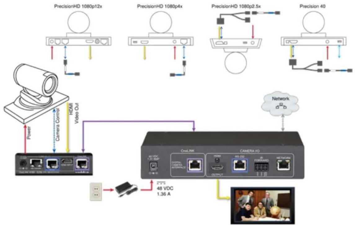
In these diagrams, the OneLINK device extends power and control to a Cisco camera, and bring video to the connected HDMI display.
Items in these diagrams:
■ OneLINK HDMI receiver and OneLINK EZIM
■ Camera-side fan-out cable (not included; used with Precision 40 and Precision HD 1080p2.5x)
■ Cisco camera (not included)
■ HDMI display and HDMI cable (not included)
■ Cat-5e cables for OneLINK and network connections (not included)
Cisco Precision 40 or Precision HD Series Camera
flowchart
graph TD
    subgraph_HD1["PrecisionHD 1080p12x"]
        A["Camera"] -->|Power| B["Monitor"]
        C["Camera Control"] -->|HDMI Video Out| B
    end
    subgraph_HD2["PrecisionHD 1080p4x"]
        D["Camera"] -->|Power| E["Monitor"]
        F["Camera"] -->|HDMI Video Out| E
    end
    subgraph_HD3["PrecisionHD 1080p2.5x"]
        G["Camera"] -->|Power| H["Monitor"]
        I["Camera"] -->|HDMI Video Out| H
    end
    subgraph_HD4["Precision 40"]
        J["Camera"] -->|Power| K["Monitor"]
        L["Camera"] -->|HDMI Video Out| K
    end
    B --> L
    E --> M["Oval/INK"]
    H --> N["CAMERA iPo"]
    K --> O["48 VDC 1.36 A"]
    N --> P["48 VDC 1.36 A"]
    style HD1 fill:#f9f,stroke:#333
    style HD2 fill:#f9f,stroke:#333
    style HD3 fill:#f9f,stroke:#333
    style HD4 fill:#f9f,stroke:#333
    style HD5 fill:#f9f,stroke:#333
    style HD6 fill:#f9f,stroke:#333
    style HD7 fill:#f9f,stroke:#333
    style HD8 fill:#f9f,stroke:#333
    style HD9 fill:#f9f,stroke:#333
    style HD10 fill:#f9f,stroke:#333
    style HD11 fill:#f9f,stroke:#333
    style HD12 fill:#f9f,stroke:#333
    style HD13 fill:#f9f,stroke:#333
    style HD14 fill:#f9f,stroke:#333
Note
If connecting to a Cisco Precision 40 or Precision HD 1080p2.5x camera, you will need to provide split cable, Cisco part number CAB-PHD4XS2-SPLIT.
Cisco Precision 60 Camera

flowchart
graph TD
    A["Video Camera"] -->|USB/USB 1.57 Mbps| B["USB/USB"]
    A -->|USB/USB 2.08 Mbps| C["USB/USB"]
    A -->|USB/USB 3.09 Mbps| D["USB/USB"]
    A -->|USB/USB 4.06 Mbps| E["USB/USB"]
    A -->|USB/USB 5.05 Mbps| F["USB/USB"]
    A -->|USB/USB 6.04 Mbps| G["USB/USB"]
    A -->|USB/USB 7.03 Mbps| H["USB/USB"]
    A -->|USB/USB 8.02 Mbps| I["USB/USB"]
    A -->|USB/USB 9.01 Mbps| J["USB/USB"]
    A -->|USB/USB 10.00 Mbps| K["USB/USB"]
    A -->|USB/USB 11.09 Mbps| L["USB/USB"]
    A -->|USB/USB 12.08 Mbps| M["USB/USB"]
    A -->|USB/USB 13.07 Mbps| N["USB/USB"]
    A -->|USB/USB 14.06 Mbps| O["USB/USB"]
    A -->|USB/USB 15.05 Mbps| P["USB/USB"]
    A -->|USB/USB 16.04 Mbps| Q["USB/USB"]
    A -->|USB/USB 17.03 Mbps| R["USB/USB"]
    A -->|USB/USB 18.02 Mbps| S["USB/USB"]
    A -->|USB/USB 19.01 Mbps| T["USB/USB"]
    A -->|USB/USB 20.00 Mbps| U["USB/USB"]
    A -->|USB/USB 21.09 Mbps| V["USB/USB"]
    A -->|USB/USB 22.08 Mbps| W["USB/USB"]
    A -->|USB/USB 23.07 Mbps| X["USB/USB"]
    A -->|USB/USB 24.06 Mbps| Y["USB/USB"]
    A -->|USB/USB 25.05 Mbps| Z["USB/USB"]
    A -->|USB/USB 26.04 Mbps| AA["USB/USB"]
    A -->|USB/USB 27.03 Mbps| AB["USB/USB"]
    A -->|USB/USB 28.02 Mbps| AC["USB/USB"]
    A -->|USB/USB 29.01 Mbps| AD["USB/USB"]
    A -->|USB/USB 30.00 Mbps| AE["USB/USB"]
    A -->|USB/USB 31.09 Mbps| AF["USB/USB"]
    A -->|USB/USB 32.08 Mbps| AG["USB/USB"]
    A -->|USB/USB 33.07 Mbps| AH["USB/USB"]
    A -->|USB/USB 34.06 Mbps| AI["USB/USB"]
    A -->|USB/USB 35.05 Mbps| AJ["USB/USB"]
    A -->|USB/USB 36.04 Mbps| AK["USB/USB"]
    A -->|USB/USB 37.03 Mbps| AL["USB/USB"]
    A -->|USB/USB 38.02 Mbps| AM["USB/USB"]
    A -->|USB/USB 39.01 Mbps| AN["USB/USB"]
    A -->|USB/USB 40.00 Mbps| AO["USB/USB"]
    A -->|USB/USB 41.09 Mbps| AP["OSI/LINK"]
    A -->|OSI/LINK 1.57 Mbps| AQ["CAMERA I/O"]
    AQ --> AR["CAMERA I/O"]
    AQ --> AS["CAMERA I/O"]
    AQ --> AT["Camera I/O"]
    AQ --> AU["Camera I/O"]
    AQ --> AV["Camera I/O"]
    AQ --> AW["Camera I/O"]
    AQ --> AX["Camera I/O"]
    AQ --> AY["Camera I/O"]
    AQ --> AZ["Camera I/O"]
    AQ --> BA["Camera I/O"]
    AQ --> BB["Camera I/O"]
    AQ --> BC["Camera I/O"]
    AQ --> BD["Camera I/O"]
    AQ --> BE["Camera I/O"]
    AQ --> BF["Camera I/O"]
    AQ --> BG["Camera I/O"]
    AQ --> BH["Camera I/O"]
    AQ --> BI["Camera I/O"]
    AQ --> BJ["Camera I/O"]
    AQ --> BK["Camera I/O"]
    AQ --> BL["Camera I/O"]
    AQ --> BM["Camera I/O"]
    AQ --> BN["Camera I/O"]
    AQ --> BO["Camera I/O"]
    AQ --> BP["Camera I/O"]
    AQ --> BQ["Camera I/O"]
    AQ --> BR["Camera I/O"]
Hardware Note: RS-232 Connections
For RS-232 connections to Cisco cameras, use the appropriate null-modem cable. Connect it as ir on the cable labels. This cable is used with the Cisco split cable CAB-PHD4XS2-SPLIT for some cameras.
Connecting a Sony or Panasonic HDMI Camera
999-9530-000/001/009
In these diagrams, the OneLINK device extends power and control to a Sony or Panasonic HDM. The OneLINK device provides HDMI video to the connected display.
Items in this diagram:
■ OneLINK HDMI receiver and OneLINK EZIM
■ Power supply and AC cord set
■ Camera with cables (not included)
■ HDMI display and cable (not included)
Panasonic AW-HE130 Camera

flowchart
graph TD
    A["User Interface"] -->|Data Flow| B["OneLINK"]
    B --> C["OneLINK"]
    C --> D["CAMERA I/O"]
    D --> E["Output"]
    E --> F["Video Panel"]
    G["Network"] --> D
    H["48 VDC / USB AMP"] --> D
    I["48 VDC / USB Media"] --> D
    J["1.36 A"] --> D
    K["Power Supply"] --> B
    L["External Display"] --> D
Sony SRG300 Camera
The SRG120 camera's connector panel looks very similar, and connects in the same way.

flowchart
graph TD
    A["Router"] -->|Data Flow| B["OneLINK"]
    B --> C["OneLINK IO"]
    C --> D["Output Device"]
    D --> E["Video Camera"]
    F["Laptop"] --> G["Network"]
    G --> C
    H["User Interface"] --> B
    I["User Interface"] --> C
    J["User Interface"] --> C
    K["User Interface"] --> C
    L["User Interface"] --> C
    M["User Interface"] --> C
    N["User Interface"] --> C
    O["User Interface"] --> C
    P["User Interface"] --> C
    Q["User Interface"] --> C
    R["User Interface"] --> C
    S["User Interface"] --> C
    T["User Interface"] --> C
    U["User Interface"] --> C
    V["User Interface"] --> C
    W["User Interface"] --> C
    X["User Interface"] --> C
    Y["User Interface"] --> C
    Z["User Interface"] --> C
    AA["User Interface"] --> C
    AB["User Interface"] --> C
    AC["User Interface"] --> C
    AD["User Interface"] --> C
    AE["User Interface"] --> C
    AF["User Interface"] --> C
    AG["User Interface"] --> C
    AH["User Interface"] --> C
    AI["User Interface"] --> C
    AJ["User Interface"] --> C
    AK["User Interface"] --> C
    AL["User Interface"] --> C
    AM["User Interface"] --> C
    AN["User Interface"] --> C
    AO["User Interface"] --> C
    AP["User Interface"] --> C
    AQ["User Interface"] --> C
    AR["User Interface"] --> C
    AS["User Interface"] --> C
    AT["User Interface"] --> C
    AU["User Interface"] --> C
    AV["User Interface"] --> C
    AW["User Interface"] --> C
    AX["User Interface"] --> C
    AY["User Interface"] --> B
Connections for HDMI Cameras Used with Codecs
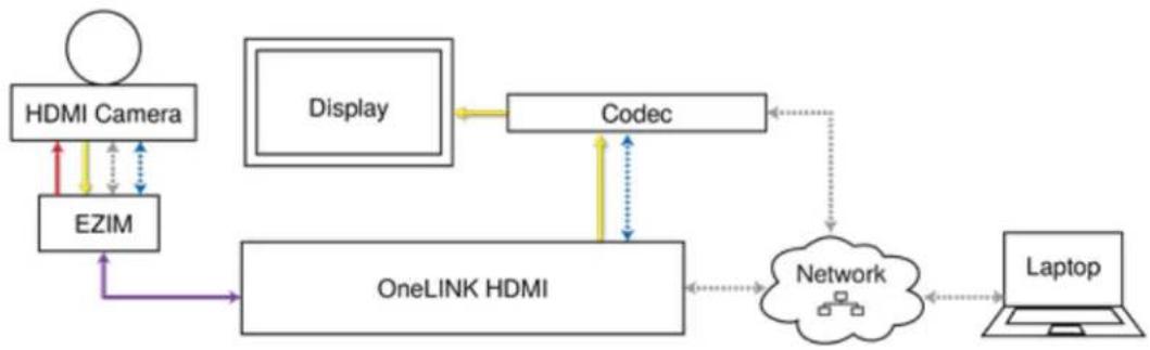
In this configuration, the OneLINK HDMI extends network connectivity, power, and control to an HI camera, and brings HDMI video from the camera to the codec. The codec may be connected to OneLINK device directly via RS-232, or they may communicate over the IP network, depending on codec.
If an IP stream is available from the camera, the OneLINK device passes it to the network. IP resolutions up to 2160p/30 are supported. HDMI output resolution and streaming parameters (including resolution) are configured on the camera, not the OneLINK device.
flowchart
graph TD
    A["HDMI Camera"] -->|red arrow| B["OneLINK HDMI"]
    C["EZIM"] -->|purple arrow| B
    D["Display"] --> E["Codec"]
    E --> B
    F["Network"] --> B
    G["Laptop"] --> H["User Interface"]
    B --> I["User Interface"]
    style A fill:#f9f,stroke:#333
    style C fill:#f9f,stroke:#333
    style D fill:#f9f,stroke:#333
    style E fill:#ccf,stroke:#333
    style F fill:#ccf,stroke:#333
    style G fill:#ccf,stroke:#333
    style H fill:#ccf,stroke:#333
Kits for HDMI Cameras Used with Codecs
This block diagram applies to:
■ OneLINK HDMI for Polycom Cameras with Polycom Codecs, 999-9520-000/001/009 – compatible with Polycom EagleEye IV camera and Polycom RealPresence Group Series codecs.
■ OneLINK HDMI for RoboSHOT HDMI Cameras with Polycom Codecs, 999-9540-000/001/009 - compatible with RoboSHOT HDMI cameras and Polycom RealPresence Group Series codecs.
■ OneLINK HDMI for Cisco Cameras with Cisco Codecs, 999-9660-000/001/009 – compatible with Cisco Precision series cameras and Cisco C20, C40, C60, SX20, and SX80 codecs.
■ OneLINK HDMI for RoboSHOT HDMI Cameras with Cisco Codecs, 999-9570-000/001/009 - Compatible with RoboSHOT HDMI cameras and Cisco C20, C40, C60, SX20, and SX80 codecs
Connecting a RoboSHOT HDMI Camera and Polycom Codec
999-9540-000/001/009
In these diagrams, the OneLINK device extends network connectivity, power, and control to a Rob HDMI camera, and connects it to a Polycom RealPresence Group Series codec. The codec provides HDMI video to the connected display.
Items in these diagrams:
■ OneLINK HDMI receiver and OneLINK EZIM
■ Power supply with AC cord set
■ RoboSHOT 12 HDMI camera (not included)
■ Polycom RealPresence Group Series codec (not included)
■ Codec-side fan-out cable, bare wires terminated with 3-position, 5mm Euro-style connector
■ HDMI display and HDMI cable (not included)
■ Laptop providing access to the camera's web interface (not included)
■ Cat-5e cables for OneLINK and network connections (not included)
RoboSHOT HDMI Camera and Polycom RealPresence Group 310 Codec
The Group 500 codec looks very similar and connects in the same way.

flowchart
graph TD
    A["Camera"] -->|48 VDC 1.36 A| B["Router"]
    B --> C["ONLINE"]
    C --> D["CAMERA I/O"]
    D --> E["Laptop"]
    E --> F["Network"]
    F --> G["Video Device"]
    G --> H["Display"]
    style A fill:#f9f,stroke:#333
    style B fill:#ccf,stroke:#333
    style C fill:#cfc,stroke:#333
    style D fill:#fcc,stroke:#333
    style E fill:#cff,stroke:#333
    style F fill:#ffc,stroke:#333
    style G fill:#cfc,stroke:#333
    style H fill:#fcc,stroke:#333
RoboSHOT HDMI Camera and Polycom RealPresence Group 700 Codec
flowchart
graph TD
    A["Camera HD"] -->|48 VDC 1.36 A| B["OneLink"]
    A --> C["Network"]
    A --> D["Router"]
    B --> E["Digital Interface"]
    B --> F["RS-270"]
    B --> G["ADDRAMO"]
    B --> H["Network"]
    C --> I["Computer"]
    D --> J["Router"]
    D --> K["Video Panel"]
    D --> L["Video Panel"]
    D --> M["Video Panel"]
    style A fill:#f9f,stroke:#333
    style B fill:#ccf,stroke:#333
    style C fill:#cfc,stroke:#333
    style D fill:#fcc,stroke:#333
    style E fill:#ffc,stroke:#333
    style F fill:#ffc,stroke:#333
    style G fill:#ffc,stroke:#333
    style H fill:#ffc,stroke:#333
    style I fill:#cfc,stroke:#333
    style J fill:#cfc,stroke:#333
    style K fill:#cfc,stroke:#333
    style L fill:#cfc,stroke:#333
Hardware Note: IR Forwarding
Use the supplied 3-position Euro-style connector to terminate the two unterminated wires of the cc fan-out cable as follows:
■ Black wire: Center position (pin 2)
■ Red wire: Right position (pin 3)
Connect this part of the fan-out cable to the IR FORWARD connector on the OneLINK HDMI re

Note
Some fan-out cables have a black/white wire instead of a red one. Wiring is the same - black black/white to pin 3.
Some older fan-out cables have the wires reversed. This will not damage the equipment. If IR f does not work when you terminate the cable per these instructions, remove power from the OneL device, disconnect the fan-out cable, and re-terminate the wires with red (or black/white) to pin 2 to pin 3. Then reconnect the cable and power up the OneLINK device again.
Hardware Note: Connection and Configuration Changes
After connecting or configuring the equipment, reboot the OneLINK device, camera, and codec. Not rebooting the OneLINK device does not affect the camera and codec; they must be rebooted sep
Connecting a Polycom EagleEye IV Camera and Polycom Codec
999-9520-000/001/009
In these diagrams, the OneLINK device extends network connectivity, power, and control to a Poly EagleEye IV camera, and connects it to a Polycom codec. The codec provides HDMI video to connected display.
Items in these diagrams:
■ OneLINK HDMI receiver and OneLINK EZIM
■ Power supply with AC cord set
■ Polycom EagleEye IV camera (not included)
■ Polycom RealPresence Group Series codec (not included)
■ Codec-side fan-out cable, bare wires terminated with 3-position, 5mm Euro-style connector
■ HDMI display and HDMI cable (not included)
■ Cat-5e cables for OneLINK and network connections (not included)
Polycom EagleEye IV Camera and Polycom RealPresence Group 310 Codec
The Group 500 codec looks very similar and connects in the same way.

flowchart
graph TD
    A["TV"] --> B["Camera"]
    B --> C["Network"]
    D["48 VDC 1.36 A"] --> E["ONLINK"]
    E --> F["CAMERA I/O"]
    F --> G["Output"]
    G --> H["Video Panel"]
    H --> I["Server"]
    J["Radio"] --> K["Radio"]
    L["Radio"] --> M["Radio"]
    N["Radio"] --> O["Radio"]
    P["Radio"] --> Q["Radio"]
    R["Radio"] --> S["Radio"]
    T["Radio"] --> U["Radio"]
    V["Radio"] --> W["Radio"]
    X["Radio"] --> Y["Radio"]
    Z["Radio"] --> AA["Radio"]
Polycom EagleEye IV Camera and Polycom RealPresence Group 700 Codec
flowchart
graph TD
    A["OneLink"] -->|48 VDC 1.37 A6| B["CAMERA ID"]
    B --> C["Network"]
    C --> D["Output"]
    D --> E["RS-210"]
    E --> F["Forward"]
    F --> G["Network"]
    G --> H["Video Panel"]
    H --> I["Display"]
    I --> J["Monitor"]
    J --> K["Display"]
    K --> L["Display"]
    L --> M["Display"]
    M --> N["Display"]
    N --> O["Display"]
    O --> P["Display"]
    P --> Q["Display"]
    Q --> R["Display"]
    R --> S["Display"]
    S --> T["Display"]
    T --> U["Display"]
    U --> V["Display"]
    V --> W["Display"]
    W --> X["Display"]
    X --> Y["Display"]
    Y --> Z["Display"]
    Z --> A
    style A fill:#f9f,stroke:#333
    style B fill:#ccf,stroke:#333
    style C fill:#cfc,stroke:#333
    style D fill:#fcc,stroke:#333
    style E fill:#cff,stroke:#333
    style F fill:#ffc,stroke:#333
    style G fill:#fcc,stroke:#333
    style H fill:#ffc,stroke:#333
    style I fill:#fcc,stroke:#333
    style J fill:#ffc,stroke:#333
    style K fill:#fcc,stroke:#333
    style L fill:#ffc,stroke:#333
    style M fill:#fcc,stroke:#333
    style N fill:#ffc,stroke:#333
    style O fill:#fcc,stroke:#333
    style P fill:#ffc,stroke:#333
    style Q fill:#fcc,stroke:#333
    style R fill:#ffc,stroke:#333
    style S fill:#fcc,stroke:#333
    style T fill:#ffc,stroke:#333
    style U fill:#fcc,stroke:#333
    style V fill:#fcc,stroke:#333
Hardware Note: IR Forwarding
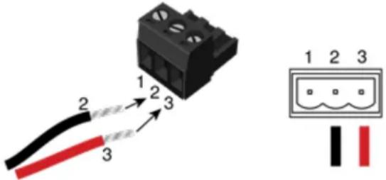
Use the supplied 3-position Euro-style connector to terminate the two unterminated wires of the cc fan-out cable as follows:
■ Black wire: Center position (pin 2)
■ Red wire: Right position (pin 3)
Connect this part of the fan-out cable to the IR FORWARD connector on the OneLINK HDMI re
Note
Some fan-out cables have a black/white wire instead of a red one. Wiring is the same - black black/white to pin 3.
Some older fan-out cables have the wires reversed. This will not damage the equipment. If IR f does not work when you terminate the cable per these instructions, remove power from the OneL device, disconnect the fan-out cable, and re-terminate the wires with red (or black/white) to pin 2 to pin 3. Then reconnect the cable and power up the OneLINK device again.
Hardware Note: Connection and Configuration Changes
After connecting or configuring the equipment, reboot the OneLINK device, camera, and codec. Not rebooting the OneLINK device does not affect the camera and codec; they must be rebooted sep
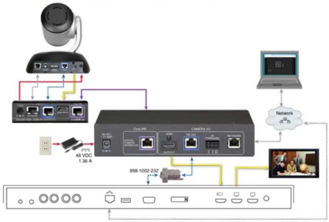
Connecting a RoboSHOT HDMI Camera and Cisco Codec
999-9570-000/001/009
In these diagrams, the OneLINK device extends network connectivity, power, and control to a Rob HDMI camera, and connects it to a Cisco codec. The codec provides HDMI video to the connection display.
Items in these diagrams:
■ OneLINK HDMI receiver and OneLINK EZIM
■ Power supply and AC cord set
■ Cisco split cable CAB-PHD4XS2-SPLIT (not included; required for SX20 codec)
■ Codec-side null modem cable (used with split cable on SX20 codec)
■ RoboSHOT 12 HDMI camera (not included)
■ Cisco codec (not included)
■ HDMI display and HDMI cable (not included)
■ Laptop providing access to the camera's web interface (not included)
■ Cat-5e cables for OneLINK and network connections (not included)
■ RS-232 adapter 998-1002-232 (used with standard Cat-5 cable on C20, C60. and SX80 codecs)
RoboSHOT HDMI Camera and Cisco C20 Codec
flowchart
graph TD
    A["User"] --> B["Device 1"]
    B --> C["Device 2"]
    C --> D["Device 3"]
    D --> E["Device 4"]
    E --> F["Device 5"]
    F --> G["Device 6"]
    G --> H["Device 7"]
    H --> I["Device 8"]
    I --> J["Device 9"]
    J --> K["Device 10"]
    K --> L["Device 11"]
    L --> M["Device 12"]
    M --> N["Device 13"]
    N --> O["Device 14"]
    O --> P["Device 15"]
    P --> Q["Device 16"]
    Q --> R["Device 17"]
    R --> S["Device 18"]
    S --> T["Device 19"]
    T --> U["Device 20"]
    U --> V["Device 21"]
    V --> W["Device 22"]
    W --> X["Device 23"]
    X --> Y["Device 24"]
    Y --> Z["Device 25"]
    Z --> AA["Device 26"]
    AA --> AB["Device 27"]
    AB --> AC["Device 28"]
    AC --> AD["Device 29"]
    AD --> AE["Device 30"]
    AE --> AF["Device 31"]
    AF --> AG["Device 32"]
    AG --> AH["Device 33"]
    AH --> AI["Device 34"]
    AI --> AJ["Device 35"]
    AJ --> AK["Device 36"]
    AK --> AL["Device 37"]
    AL --> AM["Device 38"]
    AM --> AN["Device 39"]
    AN --> AO["Device 40"]
    AO --> AP["Device 41"]
    AP --> AQ["Device 42"]
    AQ --> AR["Device 43"]
    AR --> AS["Device 44"]
    AS --> AT["Device 45"]
    AT --> AU["Device 46"]
    AU --> AV["Device 47"]
    AV --> AW["Device 48"]
RoboSHOT HDMI Camera and Cisco C60 Codec
The C40 codec looks very similar and connects in the same way.

flowchart
graph TD
    A["Camera"] -->|48 VDC 1.36 A| B["USB Interface"]
    B --> C["CNC"]
    C --> D["ICU LINK"]
    D --> E["ICU"]
    E --> F["CAMERA I/O"]
    F --> G["Network"]
    G --> H["Laptop"]
    H --> I["Camera Control"]
    I --> J["998-1002-232"]
RoboSHOT HDMI Camera and Cisco SX20 Codec

flowchart
graph TD
    A["Camera"] -->|48 VDC 1.36 A| B["Router"]
    B --> C["Oval RIK"]
    C --> D["CAMERA I/O"]
    D --> E["Laptop"]
    E --> F["Network"]
    F --> G["Video Panel"]
    G --> H["Monitor"]
    H --> I["Display"]
    I --> J["User Interface"]
    J --> K["Wireless Port"]
    K --> L["Wireless Port"]
    L --> M["Wireless Port"]
    M --> N["Wireless Port"]
    N --> O["Wireless Port"]
    O --> P["Wireless Port"]
    P --> Q["Wireless Port"]
    Q --> R["Wireless Port"]
    R --> S["Wireless Port"]
    S --> T["Wireless Port"]
    T --> U["Wireless Port"]
    U --> V["Wireless Port"]
    V --> W["Wireless Port"]
    W --> X["Wireless Port"]
    X --> Y["Wireless Port"]
    Y --> Z["Wireless Port"]
    Z --> AA["Wireless Port"]
    AA --> AB["Wireless Port"]
    AB --> AC["Wireless Port"]
    AC --> AD["Wireless Port"]
    AD --> AE["Wireless Port"]
    AE --> AF["Wireless Port"]
Note
If connecting to a Cisco SX20 codec, you will need to provide a Cisco split cable, Cisco part PHD4XS2-SPLIT.
RoboSHOT HDMI Camera and Cisco SX80 Codec

flowchart
graph TD
    A["Camera"] --> B["Network"]
    B --> C["48 VDC 1.36 A"]
    C --> D["48 VDC 1.37 AMP"]
    D --> E["OnLink"]
    E --> F["CAMERA IO"]
    F --> G["Output"]
    G --> H["Computer"]
    H --> I["Network"]
    I --> J["48 VDC"]
    J --> K["Camera Control"]
    K --> L["48 VDC"]
Hardware Note: RS-232 Connections
For RS-232 connections to Cisco gear using DE-9 connectors, use the 998-1002-232 RJ-45 to DE adapter. Its wiring differs from the 998-1001-232 adapter shipped with many Vaddio products.
For RS-232 connections to Cisco gear using the Cisco split cable, use the appropriate null-modem the RJ-45 side of the split cable. Connect the null-modem cable as indicated on the cable label
Hardware Note: Connection and Configuration Changes
After connecting or configuring the equipment, reboot the OneLINK device, camera, and codec. Not rebooting the OneLINK device does not affect the camera and codec; they must be rebooted sep
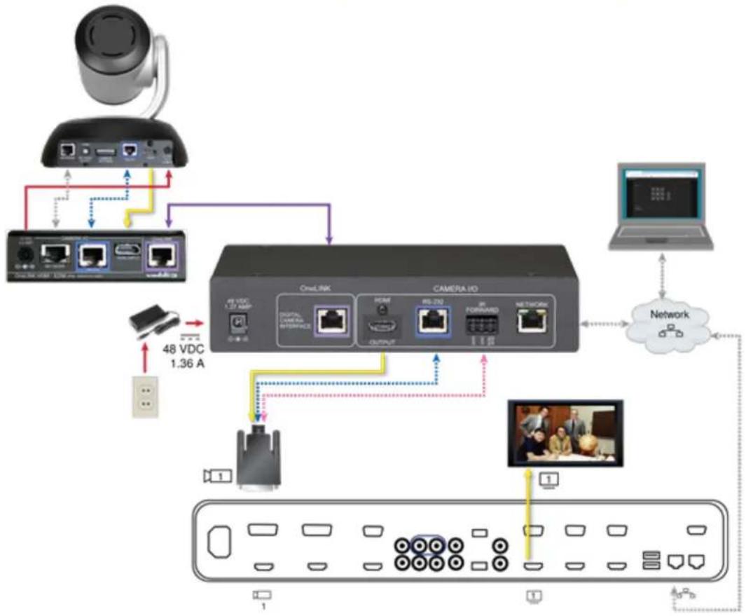
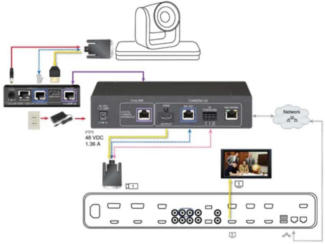
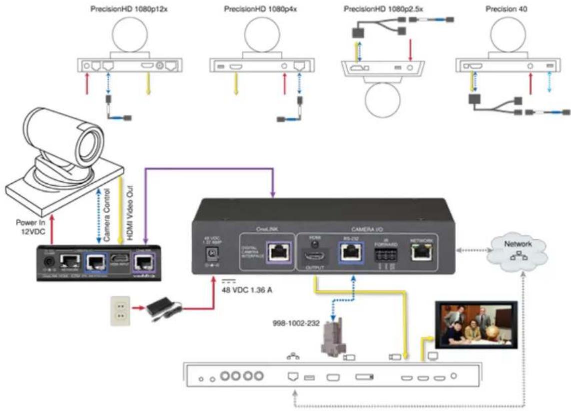
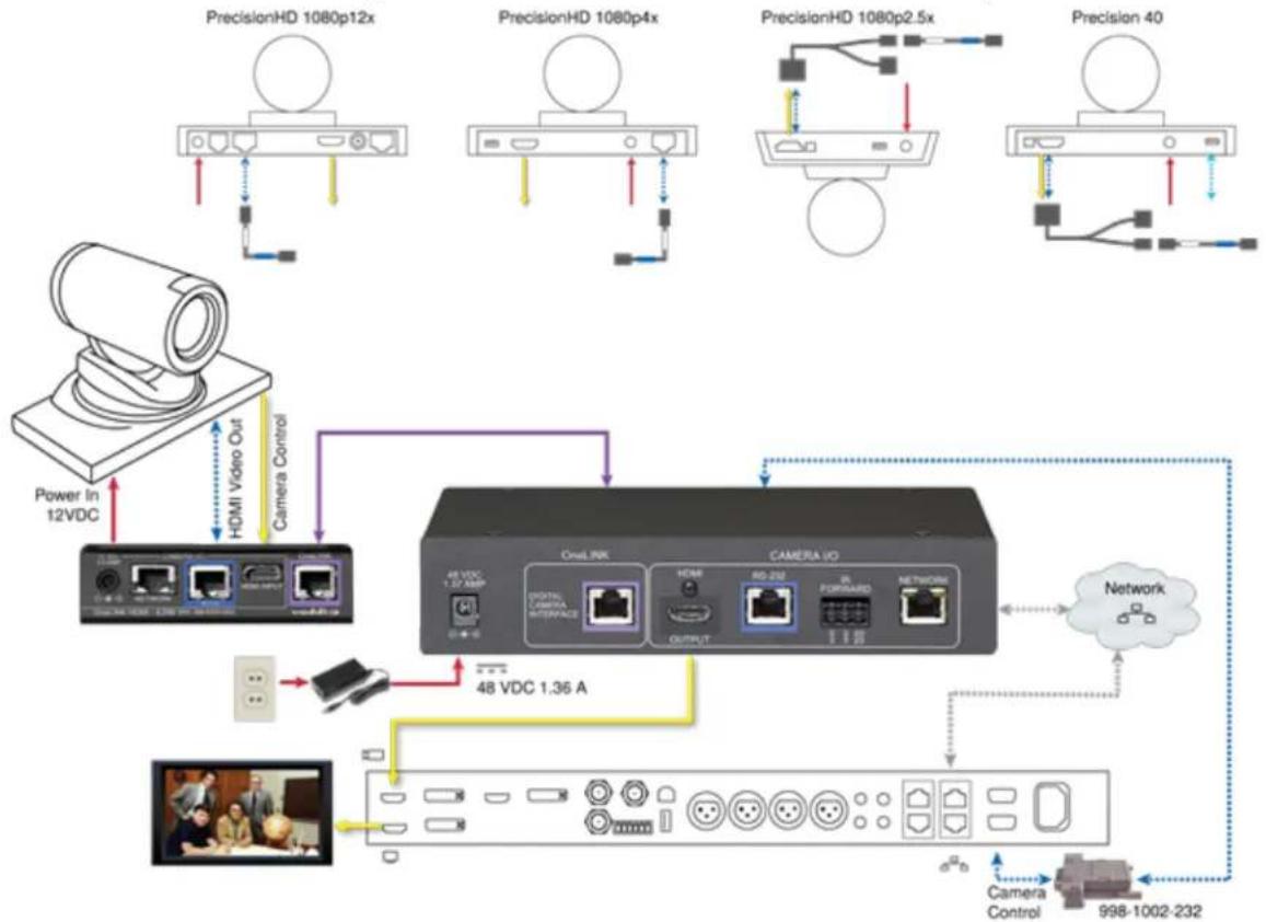
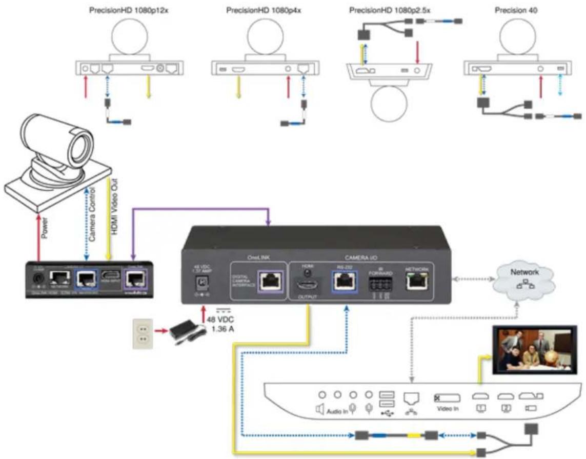
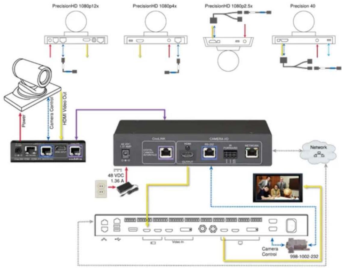
Connecting a Cisco Camera and Codec
999-9560-000/001/009
In these diagrams, the OneLINK device extends power and control to a Cisco camera, and connects Cisco codec. The codec provides HDMI video to the connected display.
Items in these diagrams:
■ OneLINK HDMI receiver and OneLINK EZIM
- Cisco split cable CAB-PHD4XS2-SPLIT (not included; required for SX20 codec and for Precision 40 and Precision HD 1080p2.5x cameras)
■ Camera-side null modem cable (used on all supported Cisco cameras)
■ Codec-side null modem cable (used with Cisco split cable on SX20 codec)
■ RS-232 adapter 998-1002-232 (used with standard Cat-5 cable on C20, C60. and SX80 codecs)
■ Cisco camera (not included)
■ Cisco codec (not included)
■ HDMI display and HDMI cable (not included)
■ Cat-5e cables for OneLINK and network connections (not included)
Note
If connecting to a Cisco SX20 codec, you will need to provide a Cisco split cable, Cisco part PHD4XS2-SPLIT. This cable is also required when connecting to a Cisco Precision 40 or Precision 1080p2.5x camera; you will need two of them if connecting one of these cameras and an SX20
Cisco Precision 40 or Precision HD Series Camera and Cisco C20 Codec
flowchart
graph TD
    A["Power In 12VDC"] --> B["Camera Control"]
    B --> C["HDMI Video Out"]
    C --> D["48 VDC 1.36 A"]
    D --> E["Osm.RK"]
    E --> F["CAMERA IO"]
    F --> G["Network"]
    G --> H["998-1002-232"]
    H --> I["Video Streaming"]
    I --> J["Internet"]
    K["PrecisionHD 1080p12x"] --> L["Camera"]
    L --> M["Output"]
    N["PrecisionHD 1080p4x"] --> O["Camera"]
    O --> P["Output"]
    Q["PrecisionHD 1080p2.5x"] --> R["Camera"]
    R --> S["Output"]
    T["Precision 40"] --> U["Camera"]
    U --> V["Output"]
    W["Network"] --> X["Video Streaming"]
Cisco Precision 40 or Precision HD Series Camera and Cisco C60 Codec The C40 codec looks very similar and connects in the same way.
flowchart
graph TD
    A["PrecisionHD 1080p12x"] --> B["Camera Control"]
    C["PrecisionHD 1080p4x"] --> D["Camera Control"]
    E["PrecisionHD 1080p2.5x"] --> F["Camera Control"]
    G["Precision 40"] --> H["Camera Control"]
    I["Power In 12VDC"] --> J["Camera Control"]
    K["48 VDC 1.36 A"] --> L["CAMERA IO"]
    M["Network"] --> N["Camera Control"]
    O["Network"] --> P["998-1002-232"]
Cisco Precision 40 or Precision HD Series Camera and Cisco SX20 Codec
flowchart
graph TD
    subgraph_HD1["PrecisionHD 1080p12x"]
        A["Server"] -->|Power| B["Camera Control"]
        B --> C["OneLink"]
        D["Server"] -->|Power| E["Camera Control"]
        E --> F["OneLink"]
        G["Server"] -->|Power| H["Camera Control"]
        H --> I["OneLink"]
        J["Desktop"] --> K["48 VDC 1.36 A"]
    end

    subgraph_HD2["PrecisionHD 1080p4x"]
        L["Server"] -->|Power| M["Camera Control"]
        M --> N["OneLink"]
        O["Server"] -->|Power| P["Camera Control"]
        P --> Q["OneLink"]
        R["Desktop"] --> S["48 VDC 1.36 A"]
        T["Camera Control"] --> U["OneLink"]
        V["Video In"] --> W["OneLink"]
        X["Video In"] --> Y["OneLink"]
        Z["Video In"] --> AA["OneLink"]
        AB["Video In"] --> AC["OneLink"]
        AD["Video In"] --> AE["OneLink"]
        AF["Video In"] --> AG["OneLink"]
        AH["Video In"] --> AI["OneLink"]
        AJ["Video In"] --> AK["OneLink"]
        AL["Video In"] --> AM["OneLink"]
        AN["Video In"] --> AO["OneLink"]
        AP["Video In"] --> AQ["OneLink"]
        AR["Video In"] --> AS["OneLink"]
        AT["Video In"] --> AU["OneLink"]
        AV["Video In"] --> AW["OneLink"]
        AX["Video In"] --> AY["OneLink"]
        AZ["Video In"] --> BA["OneLink"]
        BB["Video In"] --> BC["OneLink"]
        BD["Video In"] --> BE["OneLink"]
        BF["Video In"] --> BG["OneLink"]
        BH["Video In"] --> BI["OneLink"]
        BJ["Video In"] --> BK["OneLink"]
        BL["Video In"] --> BM["OneLink"]
        BN["Video In"] --> BO["OneLink"]
        BP["Video In"] --> BQ["OneLink"]
        BR["Video In"] --> BS["OneLink"]
        BT["Video In"] --> BU["OneLink"]
        BV["Video In"] --> BW["OneLink"]
        BX["Video In"] --> BYB["OneLink"]
        BZ["Video In"] --> BQ
        CA["Video In"] --> BQ
        CB["Video In"] --> BQ
        CC["Video In"] --> BQ
        DD["Video In"] --> BE
    end

    subgraph_HD3["PrecisionHD 1080p2.5x"]
        D1["PrecisionHD 1080p2.5x"] --> D2["PrecisionHD 1080p2.5x"]
        D3["PrecisionHD 1080p2.5x"] --> D4["PrecisionHD 1080p2.5x"]
        D5["PrecisionHD 1080p2.5x"] --> D6["PrecisionHD 1080p2.5x"]
        D7["PrecisionHD 1080p2.5x"] --> D8["PrecisionHD 1080p2.5x"]
        D9["PrecisionHD 1080p2.5x"] --> D10["PrecisionHD 1080p2.5x"]
    end

    subgraph_HD4["PrecisionHD 40"]
        E1["PrecisionHD 40"] --> E2["PrecisionHD 40"]
        E3["PrecisionHD 40"] --> E4["PrecisionHD 40"]
        E5["PrecisionHD 40"] --> E6["PrecisionHD 40"]
        E7["PrecisionHD 40"] --> E8["PrecisionHD 40"]
    end

    subgraph_HD5["PrecisionHD 1080p12x"]
        L1["PrecisionHD 1080p12x"] --> L2["PrecisionHD 1080p12x"]
        L3["PrecisionHD 1080p12x"] --> L4["PrecisionHD 1080p12x"]
        L5["PrecisionHD 1080p12x"] --> L6["PrecisionHD 1080p12x"]
    end

    subgraph_HD6["PrecisionHD 1080p4x"]
        M1["PrecisionHD 1080p4x"] --> M2["PrecisionHD 1080p4x"]
        M3["PrecisionHD 1080p4x"] --> M4["PrecisionHD 1080p4x"]
    end

    subgraph_HD7["PrecisionHD 1080p2.5x"]
        N1["PrecisionHD 1080p2.5x"] --> N2["PrecisionHD 1080p2.5x"]
        N3["PrecisionHD 1080p2.5x"] --> N4["PrecisionHD 1080p2.5x"]
    end

    subgraph_HD8["PrecisionHD 40"]
        O1["PrecisionHD 40"] --> O2["PrecisionHD 40"]
    end

    subgraph_HD9["PrecisionHD 1080p12x"]
        P1["PrecisionHD 1080p12x"] --> P2["PrecisionHD 1080p12x"]
    end

    subgraph_HD10["PrecisionHD 1080p4x"]
        Q1["PrecisionHD 1080p4x"] --> Q2["PrecisionHD 1080p4x"]
    end

    subgraph_HD11["PrecisionHD 1080p2.5x"]
        R1["PrecisionHD 1080p2.5x"] --> R2["PrecisionHD 1080p2.5x"]
    end

    subgraph_HD12["PrecisionHD 40"]
        S1["PrecisionHD 40"] --> S2["PrecisionHD 40"]
    end

    subgraph_HD13["PrecisionHD 1080p12x"]
        T1["PrecisionHD 1080p12x"] --> T2["PrecisionHD 1080p12x"]
    end

    subgraph_HD14["PrecisionHD 40"]
        U1["PrecisionHD 40"] --> U2["PrecisionHD 40"]
    end

    subgraph_HD15["PrecisionHD 1080p4x"]
        V1["PrecisionHD 1080p4x"] --> V2["PrecisionHD 1080p4x"]
    end

    subgraph_HD16["PrecisionHD 40"]
        W1["PrecisionHD 40"] --> W2["PrecisionHD 40"]
    end

    subgraph_HD17["PrecisionHD 1080p2.5x"]
        X1["PrecisionHD 1080p2.5x"] --> X2["PrecisionHD 1080p2.5x"]
    end

    subgraph_HD18["PrecisionHD 40"]
        Y1["PrecisionHD 40"] --> Y2["PrecisionHD 40"]
    end

    subgraph_HD19["PrecisionHD 1080p12x"]
        Z1["PrecisionHD 1080p12x"] --> Z2["PrecisionHD 1080p12x"]
    end

    subgraph_HD20["PrecisionHD 40"]
        AA1["PrecisionHD 40"] --> ABP["CAMERA ID: OneLink, HDMI, OUT"]
    end

    subgraph_HD21["PrecisionHD 1080p4x"]
        ABP["Camera ID: OneLink, HDMI, OUT, OUT, HDMI, OUT, HDMI, OUT, HDMI, OUT, HDMI, OUT, HDMI, OUT, HDMI, OUT, HDMI, Out, HDMI, Out, HDMI, Out, HDMI, Out, HDMI, Out, HDMI, Out, HDMI, Out, HDMI, Out, HDMI, Out, HDMI, Out, HDMI, Out, HDMI, Out, HDMI, Out, HDMI, Out, HDMI, Out, HDMI, Out, HDMI, Out, HDMI, Out, HDMI, Out, HDMI, Out, HDMI, Out, HDMI, Out, HDMI, Out, HDMI, Out, HDMI, Out, HDMI,Out, HDMI, Out, HDMI, Out, HDMI, Out, HDMI, Out, HDMI, Out, HDMI, Out, HDMI, Out, HDMI, Out, HDMI, Out, HDMI, Out, HDMI, Out, HDMI, Out, HDMI, Out, HDMI, Out, HDMI, Out, HDMI, Out, HDMI, Out, HDMI, Out, HDMI, Out, HDMI, Out, HDMI, Out, HDMI, Out, HDMI, Out, HDMI, Out, HDMI, Outside Time (Cloud)"]
    end

    subgraph HD3
            A
            B
            C
            D
            E
            F
            G
            H
            I
            J
            K
            L
            M
            N
            O
            P
            Q
            R
            S
            T
            U
            V
            W
            X
            Y
            Z
            AA
            AB
            AC
            AD
            AE
            AF
            AG
            AH
            AI
            AJ
            AK
            AL
            AM
            AN
            AO
            AP
            AQ
            AR
            AS
            AT
            AU
            AV
            AW
            AX
            AY
            AZ
            BA
            BB
            BC
            BD
            BE
            BF
            BG
            BH
            BI
            BJ
            BK
            BL
            BM
            BN
            BO
            BP
            BQ
            BR
            BS
            BT
            BU
            BV
            BW
            BX
            BY
            BZ
            BAZ
            BBZ
            BCZ
            BDZ
            BEZ
            BFZ
            BGZ
            BHZ
            BIZZ
            BJZZ
            BKZZ
            BLZZ
            BMZZ
            BAZZ
            BBZZ
            BCZZ
            BDZZ
            BEZZ
            BFZZ
            BGZZ
            BHZZ
            BIZZ
            BJZZ
            BKZZ
            BLZZ
            BMZZ
            BFZZ
            BGZZ
            BHZZ
            BIZZ
            BJZZ
            BFZZ
            BGZZ
                    Next
Cisco Precision 40 or Precision HD Series Camera and Cisco SX80 Codec
flowchart
graph TD
    A["PrecisionHD 1080p12x"] -->|Power| B["Camera Control"]
    C["PrecisionHD 1080p4x"] -->|HDMI Video Out| D["Output"]
    E["PrecisionHD 1080p2.5x"] -->|HDMI Video Out| F["Output"]
    G["Precision 40"] -->|HDMI Video Out| H["Output"]
    I["Other Devices"] --> J["OutLINK"]
    J --> K["CAMERA ID"]
    K --> L["Network"]
    M["48 VDC 1.36 A"] --> N["Video In"]
    N --> O["Camera Control"]
    O --> P["998-1002-232"]
Cisco Precision 60 Camera and Cisco SX80 Codec

flowchart
graph TD
    A["Video Client"] -->|Power| B["OneLink"]
    A -->|Network| C["CAMERA Io"]
    C --> D["Network"]
    C --> E["48 VDC 1.37 AMP"]
    C --> F["48 VDC 1.36 A"]
    C --> G["48 VDC 1.37 AMP"]
    C --> H["48 VDC 1.36 A"]
    C --> I["48 VDC 1.36 A"]
    C --> J["48 VDC 1.36 A"]
    C --> K["48 VDC 1.36 A"]
    C --> L["48 VDC 1.36 A"]
    C --> M["48 VDC 1.36 A"]
    C --> N["48 VDC 1.36 A"]
    C --> O["48 VDC 1.36 A"]
    C --> P["48 VDC 1.36 A"]
    C --> Q["48 VDC 1.36 A"]
    C --> R["48 VDC 1.36 A"]
    C --> S["48 VDC 1.36 A"]
    C --> T["48 VDC 1.36 A"]
    C --> U["48 VDC 1.36 A"]
    C --> V["48 VDC 1.36 A"]
    C --> W["48 VDC 1.36 A"]
    C --> X["48 VDC 1.36 A"]
    C --> Y["48 VDC 1.36 A"]
    C --> Z["48 VDC 1.36 A"]
Hardware Note: RS-232 Connections
For RS-232 connections to Cisco gear using DE-9 connectors, use the 998-1002-232 RJ-45 to DE adapter. Its wiring differs from the 998-1001-232 adapter shipped with many Vaddio products.
For RS-232 connections to Cisco gear using the Cisco split cable, use the appropriate null-modem the RJ-45 side of the split cable. Connect the null-modem cable as indicated on the cable label
Hardware Note: Connection and Configuration Changes
After connecting or configuring the equipment, reboot the OneLINK device, camera, and codec. Not rebooting the OneLINK device does not affect the camera and codec; they must be rebooted sep
Camera Configuration
To use IR forwarding on Cisco cameras with Cisco C-series codecs, go to the camera's admin and set IR to Auto.
To use IR forwarding on Cisco cameras with Cisco SX20 and SX80 codecs, go to the camera's settings and set IR to On.
Powering Up the Equipment
Power up the connected equipment that is not powered by the OneLINK device (such as display: party control devices), then connect power to the OneLINK device. The connected camera and the OneLINK device power up together.
Next Steps
The OneLINK device is now ready to configure and use. This information is available in the Complete
Manual for the OneLINK HDMI Camera Extension.
You may need to configure the following settings on the camera:
■ Network settings
■ Streaming
■ Video resolution and other camera settings
Refer to the camera's manual for details.
Operation, Storage, and Care
For smears or smudges on the product, wipe with a clean, soft cloth. Use a lens cleaner on use any abrasive chemicals.
Keep this device away from food and liquids.
Do not operate or store the device under any of the following conditions:
■ Temperatures above 40°C (104°F) or below 0°C (32°F)
■ High humidity, condensing or wet environments
■ Inclement weather
■ Severe vibration
■ Lateral acceleration of more than 27G
■ Dry environments with an excess of static discharge
Do not attempt to take this product apart. There are no user-serviceable components inside.
Compliance Statements and Declarations of Conformity
Compliance testing was performed to the following regulations:
| FCC Part 15 (15.107, 15.109), Subpart B Class A | |
| ICES-003, Issue 6, January 2016 Class A | |
| EN 55024, 2010 Class A | |
| EN 55032, 2012 Class A | |
| EN 60950-1: 2006 + A11: 2009 + A1: 2010 + A12: 2011 + A2: 2013 | |
| KN24 2008 (CISPR 24: 1997 + A1: 2000 + A2: 2002) Class A | |
| EMC Directive 2014/30/EU Class A |
Safety
FCC Part 15 Compliance
This equipment has been tested and found to comply with the limits for a Class A digital device Part 15, Subpart B, of the FCC Rules. These limits are designed to provide reasonable protection harmful interference when the equipment is operated in a commercial environment. This equipment generates, uses, and can radiate radio frequency energy and, if not installed and used in accordance with the instruction manual, may cause harmful interference to radio communications. Operation of this equipment in a residential area is likely to cause harmful interference in which case the user will to correct the interference at his/her own expense.
Operation is subject to the following two conditions: (1) This device may not cause interference, and (2) This device must accept any interference including interference that may cause undesired operation of the device.
Changes or modifications not expressly approved by Milestone AV Technologies can affect emission compliance and could void the user's authority to operate this equipment.
ICES-003 Compliance
This digital apparatus does not exceed the Class A limits for radio noise emissions from digital set out in the Radio Interference Regulations of the Canadian Department of Communications.
This product has been evaluated for Electromagnetic Compatibility under the EMC Directive for Emi and Immunity and meets the requirements for a Class A digital device. In a domestic environme product may cause radio interference in which case the user may be required to take adequate
Standard(s) To Which Conformity Is Declared:

| EMC Directive 2014/30/EU | |
| EN 55032: 2012 Multimedia Equipment | Emissions Requirements |
| EN 55024: 2010 IT Immunity Characteristics | |
| EN 61000-4-2 + Amendments A1, A2 | Electrostatic Discharge |
| EN 61000-4-3 + A1 Radiated Immunity | |
| EN 61000-4-4 + Corrigendum Electrical | Fast Transients |
| EN 61000-4-5 Surge Immunity | |
| EN 61000-4-6 Conducted Immunity | |
| EN 61000-4-8 Power Frequency Magnetic Field | |
| EN 61000-4-11 Voltage Dips, Interrupts | and Fluctuations |
| KN24 2008 (CISPR 24: 1997 + A1:A2: 2002) | 2000mmunity Characteristics |
| EN 61000-4-2 Electrostatic Discharge | |
| EN 61000-4-3 Radiated Immunity | |
| EN 61000-4-4 Electrical Fast Transients | |
| EN 61000-4-5 Surge Immunity | |
| EN 61000-4-6 Conducted Immunity | |
| EN 61000-4-8 Power Frequency Magnetic Field | |
| EN 61000-4-11 Voltage Dips, Interrupts | and Fluctuations |
| Low Voltage Directive 2014/35/EU | |
| IEC 60950-1: 2005 (2nd Edition); Am+ Am 2: 2013 | Safety2009 |
| EN 60950-1: 2006 + A11: 2009 + A12: 2011 + A2: 2013 | Safe2010 + |
| RoHS Directive 2011/65/EU | |
Warranty Information
See Vaddio Warranty, Service and Return Policies posted on support.vaddio.com for complete details.
Hardware* warranty: Two (2) year limited warranty on all parts and labor for Vaddio manufactured
products. Vaddio warrants its manufactured products against defects in materials and workmanship for period of two years from the day of purchase, to the original purchaser, if Vaddio receives notice defects during the warranty. Vaddio, at its option, will repair or replace products that prove to be defective. Vaddio manufactures its hardware products from parts and components that are new or equivalent to new in accordance with industry standard practices.
Exclusions: The above warranty shall not apply to defects resulting from improper or inadequate maintenance by the customer, customers applied software or interfacing, unauthorized modifications or misuse, mishandling, operation outside the normal environmental specifications for the product, use of incorrect power supply, modified power supply or improper site operation and maintenance. OEM and special order products manufactured by other companies are excluded and are covered by the manufacturer's warranty.
Vaddio Customer Service: Vaddio will test, repair, or replace the product or products without charge if the
unit is under warranty. If the product is out of warranty, Vaddio will test then repair the product products. The cost of parts and labor charge will be estimated by a technician and confirmed by customer prior to repair. All components must be returned for testing as a complete unit. Vaddio will accept responsibility for shipment after it has left the premises.
Vaddio Technical Support: Vaddio technicians will determine and discuss with the customer the criteria
for repair costs and/or replacement. Vaddio Technical Support can be contacted by email at support@vaddio.com or by phone at one of the phone numbers listed on support.vaddio.com.
Return Material Authorization (RMA) number: Before returning a product for repair or replacement
request an RMA from Vaddio's technical support. Provide the technician with a return phone number mail address, shipping address, product serial numbers and original purchase order number. Describe reason for repairs or returns as well as the date of purchase. See the General RMA Terms ar section for more information. RMAs are valid for 30 days and will be issued to Vaddio dealers users must return products through Vaddio dealers. Include the assigned RMA number in all correspondence with Vaddio. Write the assigned RMA number clearly on the shipping label of the returning the product. All products returned for credit are subject to a restocking charge without exception. Special order product are not returnable.
Voided warranty: The warranty does not apply if the original serial number has been removed or if the
product has been disassembled or damaged through misuse, accident, modifications, use of incorrect power supply, use of a modified power supply or unauthorized repair.
Shipping and handling: Vaddio will not pay for inbound shipping transportation or insurance charges or
accept any responsibility for laws and ordinances from inbound transit. Vaddio will pay for outbound shipping, transportation, and insurance charges for all items under warranty but will not assume responsibility for loss and/or damage by the outbound freight carrier. If the return shipment appears damaged, retain the original boxes and packing material for inspection by the carrier. Contact your immediately.
Products not under warranty: Payment arrangements are required before outbound shipment for all out of warranty products.
Index
A
anatomy of the EZCamera Interface Module 8
anatomy of the OneLINK device 7
C
cable connectors 7-9
cables 2, 9, 16-17, 19, 24, 30, 33, 37, 42
Cisco split 17, 24, 37, 42
maximum length 2, 9
null-modem 19, 24, 37, 42
Polycom fan-out, codec, terminating 16, 33
Polycom fan-out, codec, terminating |
Models.All OneLINK HDMI |
Models.All OneLINK HDMI [54] 30
capabilities 2
cleaning 43
configuring 42
IR forwarding on Cisco cameras 42
connection diagram 11-15, 17-29, 31-32, 34-42
block, HDBaseT camera 11
block, HDBaseT camera with codec 13
block, HDMI camera 20
block, HDMI camera with codec 27
Cisco Precision 40 23
Cisco Precision 40 with Cisco C20 38
Cisco Precision 40 with Cisco C40 39
Cisco Precision 40 with Cisco C60 39
Cisco Precision 40 with Cisco SX20 40
Cisco Precision 40 with Cisco SX80 41
Cisco Precision 60 24
Cisco Precision 60 with Cisco SX80 42
Cisco Precision HD 23
Cisco Precision HD with Cisco C20 38
Cisco Precision HD with Cisco C40 39
Cisco Precision HD with Cisco C60 39
Cisco Precision HD with Cisco SX20 40
Cisco Precision HD with Cisco SX80 41
Panasonic AW-HE130 25
Polycom EagleEye IV 22
Polycom EagleEye IV with Polycom RPG 310 31
Polycom EagleEye IV with Polycom RPG 500 31
Polycom EagleEye IV with Polycom RPG 700 32
RoboSHOT HDMI 21
RoboSHOT HDMI with Cisco C20 34
RoboSHOT HDMI with Cisco C40 35
RoboSHOT HDMI with Cisco C60 35
RoboSHOT HDMI with Cisco SX20 36
RoboSHOT HDMI with Cisco SX80 37
RoboSHOT HDMI with Polycom RPG 310 28
RoboSHOT HDMI with Polycom RPG 500 28
RoboSHOT HDMI with Polycom RPG 700 29
Sony SRG120 26
Sony SRG300 26
Vaddio HDBaseT 12
Vaddio HDBaseT with Cisco C20 17
Vaddio HDBaseT with Cisco C40 18
Vaddio HDBaseT with Cisco C60 18
Vaddio HDBaseT with Cisco SX20 18
Vaddio HDBaseT with Cisco SX80 19
Vaddio HDBaseT with Polycom RPG 310 14
Vaddio HDBaseT with Polycom RPG 500 14
Vaddio HDBaseT with Polycom RPG 700 15
visual conventions 11
connectors 7-10
identification 7-8
pin-out, IR forwarding 10
pin-outs, RS-232 10
customer-provided items 12, 14, 17, 21-23, 25, 28, 31, 34, 38
D
damage, preventing 9
F
front panel display 7
H
hardware reset 7
|
installation 11
mounting 11
IP address display 7
IR forwarding 10, 16, 30, 33, 42
connector pin-out 10
items you will need 12, 14, 17, 21-23, 25, 31, 34, 38
K
key for connection diagrams 11
kits 1, 3-6, 12-14, 17, 20-23, 25, 27-28, 338
for Cisco cameras 6, 23
for Cisco cameras with Cisco codecs 6, 20, 27, 38
for Panasonic cameras 4, 20, 25
for Polycom cameras 5, 22
for Polycom cameras with Polycom codecs 5, 20, 27, 31
for RoboSHOT HDMI cameras 4, 20-21
for RoboSHOT HDMI cameras with Cisco codecs 6, 27, 34
for RoboSHOT HDMI cameras with Polycom codecs 27-28
for RoboSHOT HDMI cameras with Poly-com Codecs 5
for Sony cameras 4, 20, 25
for Vaddio HDBaseT cameras 3, 12
for Vaddio HDBaseT cameras with Cisco codecs 4, 13, 17
for Vaddio HDBaseT cameras with Polycom codecs 3, 13-14
pin-outs 10
for IR forwarding connector 10
28or RS-232 connectors 10
Polycom fan-out cable, codec, terminating 16
power on/power off 43
product capabilities 2
product returns and repairs 46
product SKUs 1, 3-6
R
reset button location 7
RJ-45 connectors, recommendation 9
RS-232 adapter for Cisco products 19, 37, 42
RS-232 connector pin-out 10
s
storage environment 43
T
temperature, operating and storage 43
W
warranty 9, 46
L
line types in diagrams 11
locations of connectors 7-8
M
MAC address display 7
0
operating environment 43
P
packing lists 3-6
999-1105-043/143/943 3
999-9520-000/001/009 5
999-9530-000/001/009 4
999-9540-000/001/009 5
999-9545-000/001/009 3
999-9560-000/001/009 6
999-9570-000/001/009 6
999-9575-000/001/009 4
999-9590-000/001/009 4
Vaddio is a brand of Legrand AV Inc.· www.legrandav.com · Phone 800.572.2011 / +1.763.971.4400 · Fax +1.763.971.4464 · Email av.vaddio.support@legrand.com
Visit us at www.legrandav.com for firmware updates, specifications, drawings, manuals, technical support information, and more.
©2019 Legrand AV Inc.
Vaddio is a registered trademark of Legrand AV Inc. All other brand names or marks are used identification purposes and are trademarks of their respective owners. All patents are protected under existing designations. Other patents pending.
A brand of legrand
Commercial AV Brands Chief | Da-Lite | Middle Atlantic | Projecta | Vaddio
vaddio®
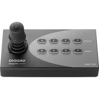
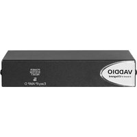
- OneLINK HDMI
- Contents
- Overview
- Note
- What's in this Guide
- Features
- Unpacking the OneLINK HDMI Camera Extension
- OneLINK HDMI for HDBaseT Cameras
- OneLINK HDMI For HDBaseT Cameras Used with Codecs
- OneLINK HDMI for Vaddio HDBaseT Cameras with Cisco Codecs, 999-9575-000/001/009
- OneLINK HDMI for HDMI Cameras
- OneLINK HDMI for RoboSHOT HDMI Cameras, 999-9590-000/001/009
- OneLINK HDMI for Sony and Panasonic Cameras, 999-9530-000/001/009
- OneLINK HDMI for HDMI Cameras Used with Codecs
- OneLINK HDMI for Polycom Cameras with Polycom Codecs, 999-9520-000/001/009
- OneLINK HDMI for RoboSHOT HDMI with Polycom
- Codecs, 999-9540-000/001/009
- OneLINK HDMI for Cisco Cameras with Cisco Codecs, 999-9560-000/001/009
- OneLINK HDMI for RoboSHOT HDMI with Cisco Codecs, 999-9570-000
- A Quick Look at the OneLINK Device
- Front Panel of the Receiver
- Connector Panel of the Receiver
- From the left:
- Connector Panel of the EZCamera Interface Module (EZIM)
- Installing the OneLINK Device
- Don't Void Your Warranty!
- Caution
- Cabling Notes
- RS-232 Connector Pin-Outs
- OneLINK Receiver - RS-232 Control Port
- OneLINK EZIM - RS-232 Control Port
- IR Forwarding Connector Pin-Out
- Mounting the OneLINK Device
- About Installations Using the Half-Recessed Ceiling Mount
- Visual Conventions for Connection Diagrams
- Connections for HDBaseT Cameras
- Kits and Systems for HDBaseT Cameras
- Connecting a Vaddio HDBaseT Camera
- 999-1105-043/143/943
- RoboSHOT HDBT Camera
- Connections for HDBaseT Cameras Used with Codecs
- Kits for HDBaseT Cameras Used with Codecs
- Connecting a Vaddio HDBaseT Camera and Polycom Codec
- 999-9545-000/001/009
- RoboSHOT HDBT Camera and Polycom RealPresence Group 310 Codec
- Hardware Note: IR Forwarding
- Hardware Note: Connection and Configuration Changes
- Connecting a Vaddio HDBaseT Camera and Cisco Codec
- 999-9575-000/001/009
- RoboSHOT HDBT Camera and Cisco C20 Codec
- RoboSHOT HDBT Camera and Cisco C60 Codec
- RoboSHOT HDBT Camera and Cisco SX20 Codec
- Hardware Note: RS-232 Connections
- Connections for HDMI Cameras
- Kits for HDMI Cameras
- Connecting a RoboSHOT HDMI Camera
- 999-9590-000/001/009
- Connecting a Polycom EagleEye IV Camera
- 999-9520-000/001/009
- Connecting a Cisco Camera
- 999-9560-000/001/009
- Cisco Precision 40 or Precision HD Series Camera
- Connecting a Sony or Panasonic HDMI Camera
- 999-9530-000/001/009
- Panasonic AW-HE130 Camera
- Sony SRG300 Camera
- Connections for HDMI Cameras Used with Codecs
- Kits for HDMI Cameras Used with Codecs
- Connecting a RoboSHOT HDMI Camera and Polycom Codec
- 999-9540-000/001/009
- RoboSHOT HDMI Camera and Polycom RealPresence Group 310 Codec
- Connecting a Polycom EagleEye IV Camera and Polycom Codec
- Polycom EagleEye IV Camera and Polycom RealPresence Group 310 Codec
- Connecting a RoboSHOT HDMI Camera and Cisco Codec
- 999-9570-000/001/009
- RoboSHOT HDMI Camera and Cisco C20 Codec
- RoboSHOT HDMI Camera and Cisco C60 Codec
- Connecting a Cisco Camera and Codec
- Camera Configuration
- Powering Up the Equipment
- Next Steps
- Operation, Storage, and Care
- Compliance Statements and Declarations of Conformity
- FCC Part 15 Compliance
- ICES-003 Compliance
- Warranty Information
- Index
- A
- C
- D
- F
- H
- |
- K
- R
- s
- T
- W
- L
- M
- 0
- P
- A brand of legrand
Brand : Vaddio
Model : OneLINK HDMI
Category : Audio/video extender