
UP-51MDU - Printer SONY - Free user manual and instructions
Find the device manual for free UP-51MDU SONY in PDF.
| Product Type | Color Video Printer |
| Brand | Sony |
| Model | UP-51MDU |
| Print Resolution | Approx. 300 dpi |
| Color Levels | 256 shades or four-color printing |
| Printing Technology | Thermal sublimation (ink ribbon) |
| Print Formats | Full page, 2, 4, 8 or 16 reduced images |
| Special Functions | Overlay, mirror, caption, white borders, multi-print |
| Video Inputs | Composite, S-Video, RGB/SYNC |
| Video Outputs | Composite, S-Video, RGB/SYNC (for monitor) |
| Image Memory | Up to 4 pages (Frame mode) or 8 half-pages (Field mode) |
| Paper Magazine Capacity | Max. 100 sheets |
| Ink Ribbon Life | Up to 200 prints per roll (UPC-510) |
| Power Supply | AC 100-240 V, 50/60 Hz |
| Dimensions (approx.) | 212 × 105 × 462 mm (W × H × D) |
| Weight (approx.) | 3.5 kg |
| Supplied Accessories | Ink ribbon holder, power cord, fan cover with filter, paper magazine, paper tray, color print set, thermal head cleaning kit, warranty card, instruction manual |
| Safety | Grounding mandatory; keep away from rain and moisture; maintenance by qualified personnel only |
| Maintenance | Regular cleaning of thermal head and fan filter |
| Consumables | Ink ribbon UPC-510 and specific print paper (color print set) |
| Repairability | Spare parts available from Sony; service by qualified personnel recommended |
| Manual | Free user manual and instruction manual in PDF format |
Frequently Asked Questions - UP-51MDU SONY
User questions about UP-51MDU SONY
0 question about this device. Answer the ones you know or ask your own.
Ask a new question about this device
Download the instructions for your Printer in PDF format for free! Find your manual UP-51MDU - SONY and take your electronic device back in hand. On this page are published all the documents necessary for the use of your device. UP-51MDU by SONY.
USER MANUAL UP-51MDU SONY
Instructions for Use Page 2
GB
The model and serial numbers are located at the rear. Record these number in the space provided below. Refer to these numbers whenever you call upon your Sony dealer regarding this product.
Model No.
Serial No.
WARNING
To prevent fire or shock hazard, do not expose the unit to rain or moisture.
To avoid electrical shock, do not open the cabinet. Refer servicing to qualified personnel only.
THIS APPARATUS MUST BE EARTHED.
For UP-51MD/51MDU/51MDP
Symbol on the products

This symbol indicates the equipotential terminal which brings the various parts of a system to the same potential.

This symbol is intended to alert the user to the presence of important operating and maintenance (servicing) instructions in the literature accompanying the appliance.
For the customers in the U.S.A.
This equipment has been tested and found to comply with the limits for a Class A digital device, pursuant to Part 15 of the FCC Rules. These limits are designed to provide reasonable protection against harmful interference when the equipment is operated in a commercial environment. This equipment generates, uses, and can radiate radio frequency energy and, if not installed and used in accordance with the instruction manual, may cause harmful interference to radio communications. Operation of this equipment in a residential area is likely to cause harmful interference in which case the user will be required to correct the interference at his own expense.
You are cautioned that any changes or modifications not expressly approved in this manual could void your authority to operate this equipment.
This device requires shielded interface cables to comply with FCC emission limits.
Important safeguards/ notices for use in the medical environments (for UP-51MD/51MDU/ 51MDP)
- All the equipments connected to this unit shall be certified according to Standard IEC60601-1, IEC60950, IEC60065 or other IEC/ISO Standards applicable to the equipments.
-
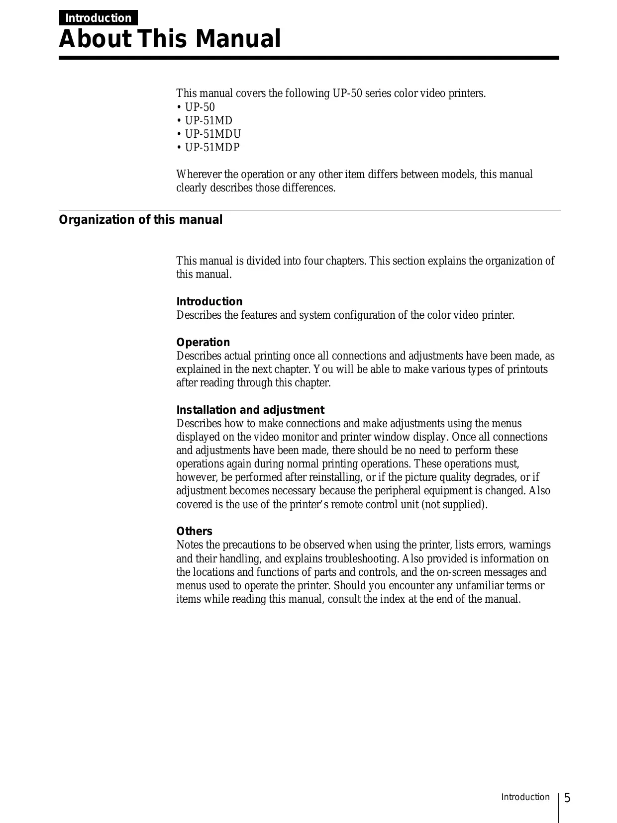
When this unit is used together with other equipment in the patient area*, the equipment shall be either powered by an isolation transformer or connected via an additional protective earth terminal to system ground unless it is certified according to Standard IEC60601-1.
-
Patient Area
For the customers in the U.S.A.
When this unit is used on 220 to 240V AC, do not use the unit itself (or as it is) unless the proper measures are taken so that the leakage current does not exceed 300 A .
- The leakage current could increase when connected to other equipment.
- This equipment generates, uses, and can radiate frequency energy. If it is not installed and used in accordance with the instruction manual, it may cause interference to other equipment. If this unit causes interference (which can be determined by unplugging the power cord from the unit), try these measures: Relocate the unit with respect to the susceptible equipment. Plug this unit and the susceptible equipment into different branch circuit. Consult your dealer. (According to standard EN60601-1-2 and CISPR11, Class B, Group 1)
Caution
When you dispose of the unit or accessories, you must obey the law in the relative area or country and the regulation in the relative hospital.
For the customers in Canada (for UP-51MD/51MDU)
This unit has been certified according to Standard CSA C22.2 NO.601.1.
| Introduction | About This Manual............5 System Overview..........7 System Configuration..........8 |
| Operation | Before Printing..........9 Loading an Ink Ribbon Cartridge..........9 Loading Paper..........12 Selecting the Input Signal..........14 Making Full-Size Image Printouts..........17 Making Printouts with the Desired User Set Number..........21 Making Multiple Copies of Identical Printouts..........23 Capturing Another Image While Printing..........26 Making Variations of Printouts..........28 Selecting the Printer Application Mode..........29 About the Memory..........32 Making a Printout of Multiple Different Reduced Images..........35 Making a Printout of Identical Reduced Images..........50 Making a Printout with an Insert..........52 Making a Printout of Mirror Images..........53 Making Printouts With a Caption..........55 Displaying the CAPTION Menu..........56 Entering a Caption..........57 Deleting the Images Stored in Memory..........64 Setting the Function of the CLEAR Button..........64 Deleting Images Stored in Memory..........66 About the Screen Display..........68 Erasing the Screen Display on the Video Monitor..........68 Displaying the Type and Remaining Amount of the Ink Ribbon..........69 |
| Installation and Adjustment | Supplied Accessories..........71 Assembly..........72 Preparing the Remote Control Unit..........73 Connections..........74 Making Connections for Capturing Video Images..........74 Making Connections for Viewing Images to be Printed..........75 Making Connections to Enable Remote Control..........76 |
(Continued)
GB
English
Installation and Adjustment
Setting Up the Printer 77
Compensating for the Input Signals 78
Matching the Video Monitor Color to the Printer Color 83
Adjusting the Printout Color 86
Changing the Printout Size/Printout Area 94
Adjusting the Color Balance 98
Selecting the Operation Mode for Automatic Printing Capabilities 104
Adjusting the Brightness of the Printer Window Display 110
Selecting Whether the Operation and Error Tones Sound 112
Setting the Baud Rate for Computer Communication 113
Selecting the Lamination Pattern 114
Registering a User Set 116
Others
Precautions 120
Safety 120
Installation 120
Before Transporting the Printer 121
Cleaning 121
Ink Ribbon and Paper 124
Specifications 125
Error/Warning Messages 129
Error Messages 129
Warning Messages 130
If the Paper Jams 131
Troubleshooting 133
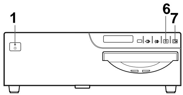
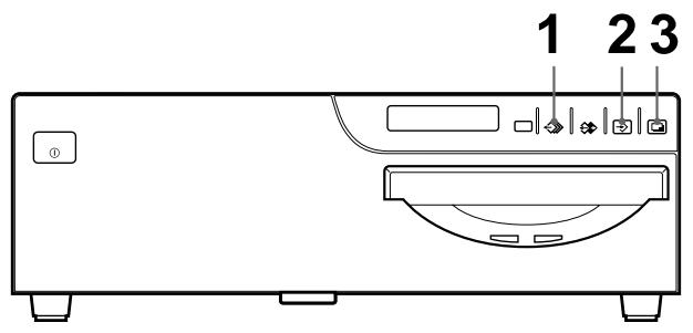
Location and Function of Parts and Controls 135
Main Panel 135
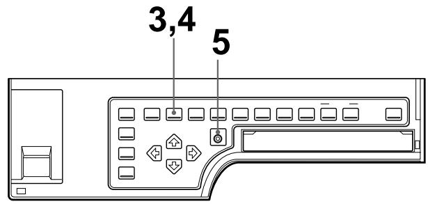
Sub Panel 136
Rear 138
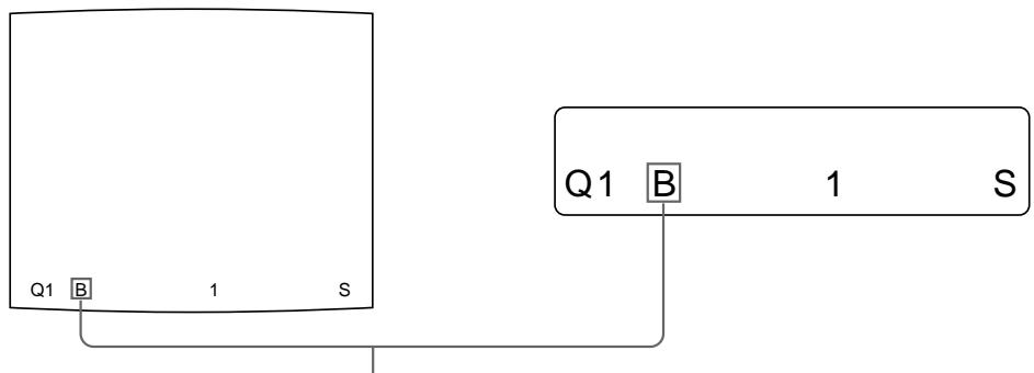
Comparing the Printer Window Display with the Video Monitor Display 139
Monitor Display 140
Index 142
This manual covers the following UP-50 series color video printers.
UP-50
UP-51MD
UP-51MDU
UP-51MDP
Wherever the operation or any other item differs between models, this manual clearly describes those differences.
Organization of this manual
This manual is divided into four chapters. This section explains the organization of this manual.
Introduction
Describes the features and system configuration of the color video printer.
Operation
Describes actual printing once all connections and adjustments have been made, as explained in the next chapter. You will be able to make various types of printouts after reading through this chapter.
Installation and adjustment
Describes how to make connections and make adjustments using the menus displayed on the video monitor and printer window display. Once all connections and adjustments have been made, there should be no need to perform these operations again during normal printing operations. These operations must, however, be performed after reinstalling, or if the picture quality degrades, or if adjustment becomes necessary because the peripheral equipment is changed. Also covered is the use of the printer's remote control unit (not supplied).
Others
Notes the precautions to be observed when using the printer, lists errors, warnings and their handling, and explains troubleshooting. Also provided is information on the locations and functions of parts and controls, and the on-screen messages and menus used to operate the printer. Should you encounter any unfamiliar terms or items while reading this manual, consult the index at the end of the manual.
Conventions used
Cross references
Throughout this manual you will find references to other sections of the manual that contain related information.
Important note
Be sure to read the sections of the manual marked Note. They explain points that you should be aware of to operate the printer correctly and prevent malfunctions.
Index
Use the index, in addition to the table of contents, to find information you need when using the printer.
Monitor and printer window displays
Some monitor displays and window displays illustrated in this manual may differ slightly from the actual display. The operation of the printer, however, remains as described in this manual.
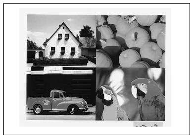
The UP-50 series color video printer is designed for capturing images from video equipment such as a VTR, and for printing out high resolution images in full color (with 256 shades per color, a total of more than 16,700,000 colors in all) in high resolution print mode (approximately 300 dpi). You can make various types of printouts. You can also add a caption to the printout. You can carry out ordinary printer operation by using the buttons and setup the printer interactively by picking from displayed menus.
Printouts that can be made with the printer
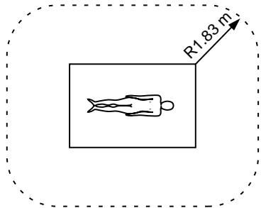
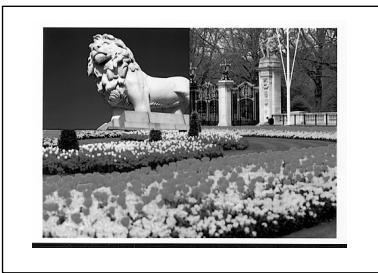
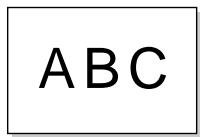
Printout of a full-size image (page 17)
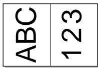
Printout of two reduced images (page 35)
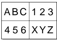
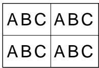
Printout of four reduced images (page 35)
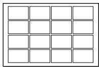
Printout of 8 reduced images (page 35)
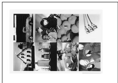
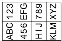
Printout of 16 reduced images (page 35)
Printout of identical images (page 50)
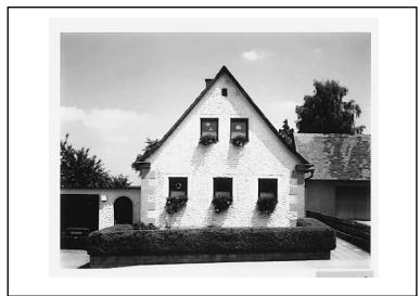
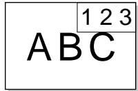
Printout with an insert (page 52)
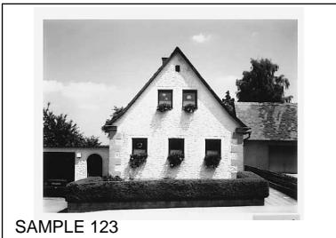
Printout with a caption (page 55)
In addition to the above printouts of multiple reduced images, printout of multiple reduced images with white borders can be made. Also, you can make a printout of mirror image(s) where the image is rotated about its vertical axis.
System Configuration
The following shows an example of a printer system configuration.
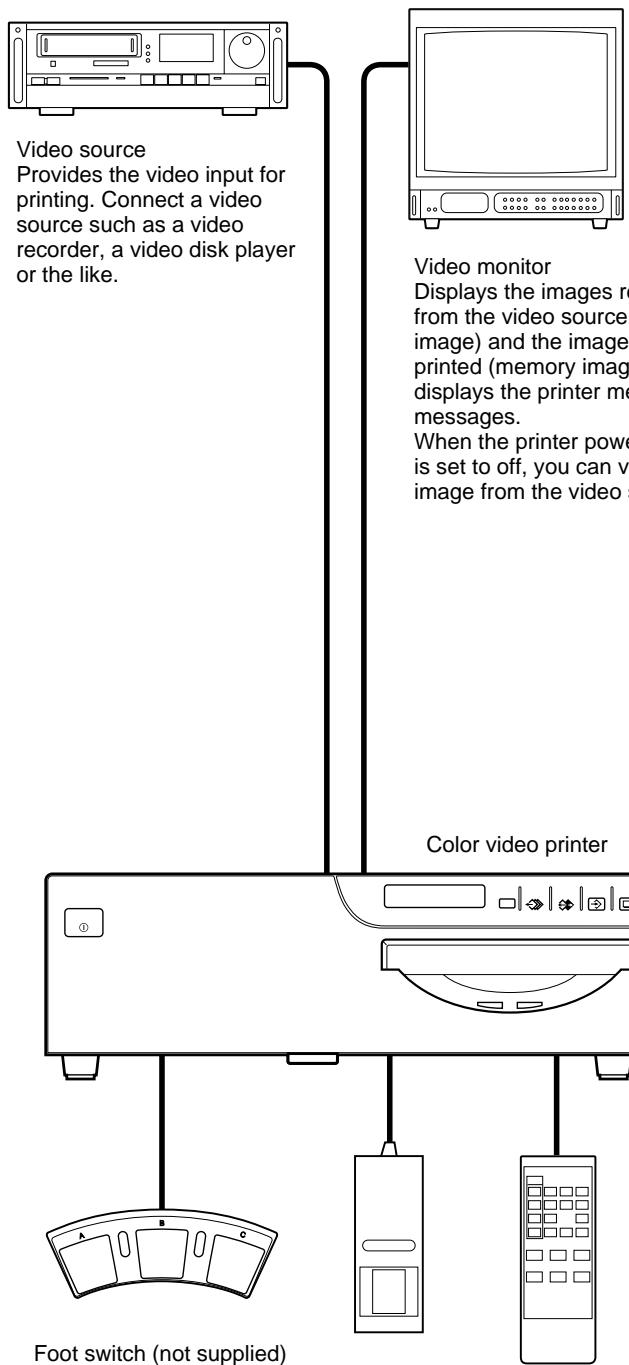
Foot switch (not supplied) allows you to operate the printer remotely.
Remote control unit (not supplied) allows you to operate the printer remotely.
This section describes the following operations that must be made prior to starting printing after mounting the paper tray and paper cover on the printer (see
"Assembly" on page 72) and making the necessary connections (see "Connections" on page 74).
- Loading an ink ribbon cartridge (See below.)
- Loading paper (See page 12.)
- Selecting the input signal (See page 14.)
Once the above operations have been completed, there should be no need to repeat them during routine printing. Perform them only when absolutely necessary.
Notes
- You can replace the ink ribbon cartridge or load paper regardless of whether the power is on or off. However, turning off the power will cause the image stored in the memory to be lost.
- Use the ink ribbon and paper contained in the same package as a pair. Before attempting to load an ink ribbon cartridge or paper, make sure that the combination of the ink ribbon and paper is compatible.
- Use only ink ribbon and paper designed for use with this printer. Failing to do so is likely to result in malfunctions. (See "Ink Ribbon and Paper" on page 124.)
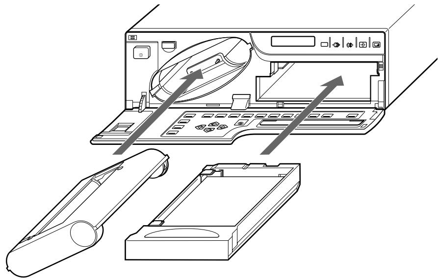
Loading an Ink Ribbon Cartridge
To make printouts, an ink ribbon cartridge (an ink ribbon holder which has been loaded with an ink ribbon) and paper must be loaded.
Load an ink ribbon into the supplied ink ribbon holder, then load the ink ribbon cartridge into the printer's ribbon compartment.
Notes
- When you use the printer for the first time, the thermal head may be out of position. Before attempting to use the ink ribbon cartridge, turn on the power so that the thermal head is placed at the correct position.
- When transporting the printer, remove the ink ribbon cartridge.
- Do not throw away the supplied ink ribbon holder even if the ink ribbon is used up. The ink ribbon holder is reusable even though the ink ribbon is not reusable.
- When you use the UPC-510 Color Printing Pack, 200 sheets of printouts can be printed for one ink ribbon roll. Even if you finish one pack of paper containing 100 sheets, do not throw away the ink ribbon. You can use the ink ribbon for another pack of papers.
- Once an ink ribbon has been completely used up, replace it. An ink ribbon is not reusable.
- Do not rewind the ink ribbon for reuse.
- Do not touch the ink ribbon or place it in a dusty location. Finger prints or dust on the ink ribbon will result in imperfect printing or malfunction of the head.
- Use the ink ribbon and paper supplied only for the initial operation check of the printer.
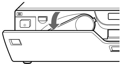
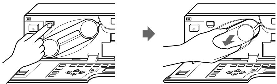
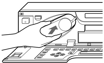
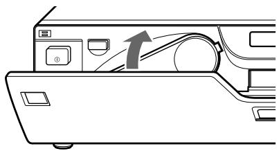
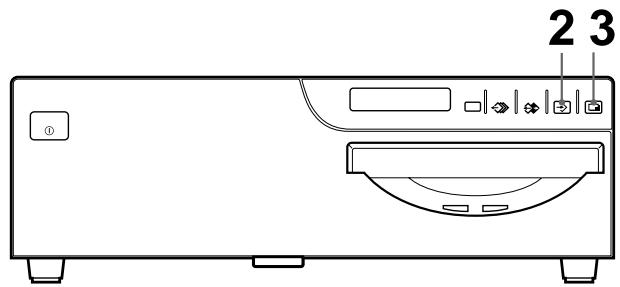
1 Open the front panel by pulling the front panel top toward you.
2 Remove the ink ribbon cartridge by pressing the EJECT button. The ink ribbon cartridge pops out.
When you use the printer for the first time, this operation is not required.
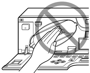
Note
Never put your hand into the ink ribbon compartment. The thermal head becomes very hot. You may burn yourself if you touch it.
When the ink ribbon cartridge cannot be ejected
Turn the power off, then back on again. Then, after a while, press the EJECT button.
Note
Turning off the power will cause the image stored in the memory to be lost. In this case, capture the image again before printing.
3 Detach the spent ink ribbon from the ink ribbon holder.
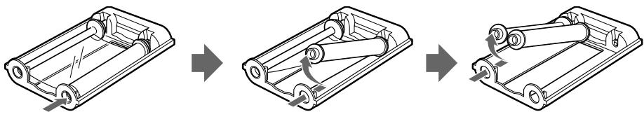
① Remove the spool holding the ink ribbon.
② Remove the other spool.
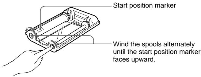
4 Load the new ink ribbon into the ink ribbon holder.
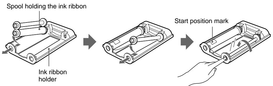
① Load the spool holding the ink ribbon into the left-hand part of the holder.
② Fit the other spool into the right-hand part of the holder.
③ Wind the spools of the ink ribbon as illustrated until a start position marker appears.
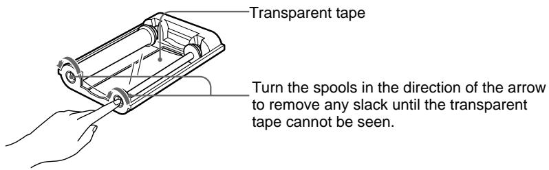
5 Remove any slack from the ink ribbon.
If the ribbon is left slack, it may be damaged when inserted.
6 Insert the ink ribbon cartridge firmly until it clicks.
Confirm that the ink ribbon cartridge is surely inserted.
If the ink ribbon cartridge stops midway, stop inserting it. You may use the wrong ink ribbon holder. Be sure to use the ink ribbon holder that is designed for this printer.
When the ink ribbon cartridge cannot be inserted
Turn the power off, then back on gain. Then, insert the ink ribbon cartridge again.
7 Close the front panel.
Notes
When storing ink ribbon cartridge:
- Avoid placing the ink ribbon in a location subject to:
high temperatures
high humidity
excessive dust
direct sunlight
- Store a partially used ink ribbon cartridge in its original packaging.
If your ink ribbon should tear
Repair the tear with transparent tape. There should be no problem with using the remaining portion of the ribbon.
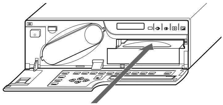
Loading Paper
To load paper, follow the procedure below. Be careful not to touch the printing surface.
Notes
- You can load paper regardless of whether the power is on or off. However, turning off the power will cause the image stored in the memory to be lost.
- Use the only paper that we recommend. Failing to do so is likely to result in malfunctions such as paper jam. Also, do not use the paper as specified for the UP-5000/5100 and UP-5500 series color video printer.
(See "Ink Ribbon and Paper" on page 124.)
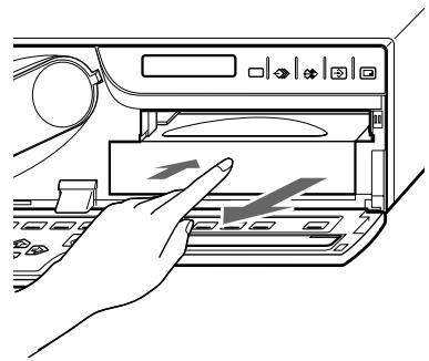
1 Open the front panel by pulling the front panel top towards you.
2 Push the paper tray. The paper tray pops out.
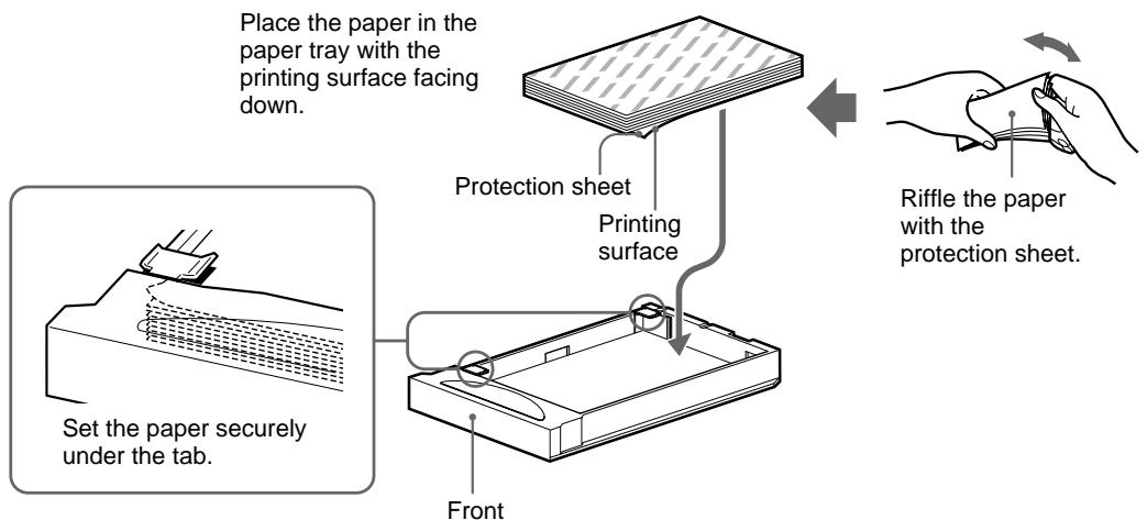
3 Place the paper in the paper tray so that the printing surface faces down with the protection sheet.
Notes
- The paper tray holds up to about 100 sheets of paper. When adding paper to a partly full tray, be careful that the total number of sheets does not exceed the limit. If you exceed this limit, paper jams may occur.
- Load the paper so that it lays flat in the paper tray. If the paper is curled, it will overflow from the paper tray and the paper may not be fed properly. Be sure to riffle the paper with the protection sheets before attempting to place the paper in the paper tray. If the printing position shifts, load fewer sheets in the paper tray.
- Do not place different types of paper in the tray.
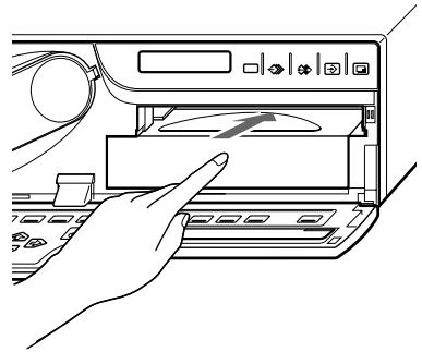
4 Slide the paper tray back into the printer until it clicks into place.
5 Close the front panel.
Notes
When handling the paper
Do not touch the printing surface. Dust or finger prints are likely to cause unsatisfactory printing or malfunction of the head. Hold the paper by the printing surface protection sheet.
When storing the paper
- Avoid storing the paper in a location subject to:
high temperatures
high humidity
excessive dust
direct sunlight
- Use the original package for storing unused paper.
Selecting the Input Signal
Before printing, select the input signal (the input connector to which the signal to be printed is being input) —VIDEO, S-VIDEO, or RGB. Once you have selected the input signal, this setting remains effective until you select another source.
The following two methods are available to select the input signal:
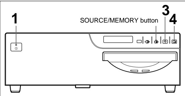
- Using the INPUT SELECT button
Using the menu
Selecting the input signal by using the INPUT SELECT button
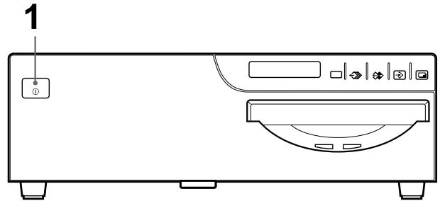
1 Turn on the video monitor and the printer.
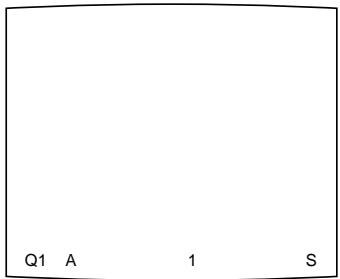
The following appears once the printer is ready to operate.
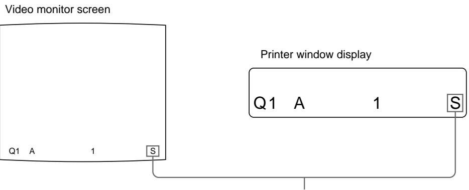
Video monitor screen
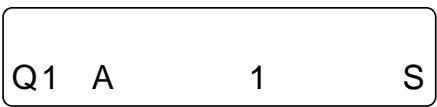
Printer window display
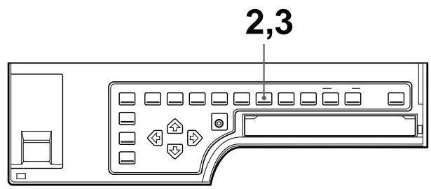
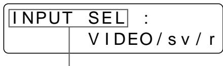
2 Press the INPUT SELECT button.
The currently selected input signal appears. The selected signal is lit in green on the video monitor screen and spelled out in the printer window display. If you do not perform any operation after you press the INPUT SELECT button, the currently set item appears for about 3 seconds, after which it disappears.
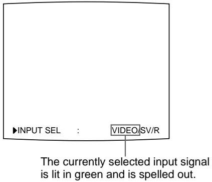
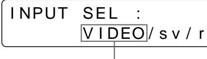
The currently selected input signal is spelled out.
3 Select the desired input signal.
Press the INPUT SELECT button repeatedly until the color of the desired input signal turns green on the monitor or until the desired input signal is spelled out on the printer window display.
Each time you press the INPUT SELECT button, the input signal changes in the order of VIDEO S-VIDEO RGB VIDEO....
The selected signal will disappear within about three seconds.
| Source signal of the image to be printed | Video monitor and printer window display (the selected input signal is spelled out) |
| Signal from video equipment connected to the VIDEO INPUT connector | V → VIDEO |
| Signal from video equipment connected to the S-VIDEO INPUT connector | SV → SVIDEO |
| Signal from video equipment connected to the RGB/SYNC INPUT connectors | R → RGB |
To confirm the currently selected input signal
Press the INPUT SELECT button. The currently selected input signal appears in green on the video monitor and is spelled out in the printer window display for about 3 seconds.
Note
If you press the INPUT SELECT button when the memory image (the image stored in memory) is displayed, the memory image will be replaced with the source image (the image sent from the source equipment).
Selecting the input signal on the menu
1 Turn on the video monitor and the printer.
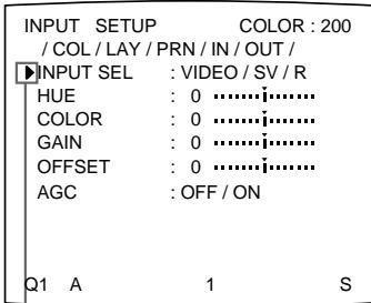
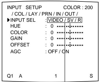
2 Press the INPUT SETUP button. The INPUT SETUP menu appears.
| INPUT SETUP COLOR : 200 | |
| / COL / LAY / PRN / IN / OUT / | |
| INPUT SEL :VIDEO / SV / R | |
| HUE : 0……… | |
| COLOR : 0……… | |
| GAIN : 0……… | |
| OFFSET : 0……… | |
| AGC : OFF / ON | |
| Q1 A 1 S |
INPUT SETUP /c/1/p/IN/o/
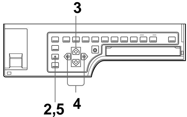
3 Select INPUT SEL by pressing the or button.
Press the or button until INPUT SEL appears.
Position the cursor at INPUT SEL by pressing the 出 or 出 button.
4 Select the desired input signal by pressing the or button.
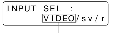
Display the spelled-out input signal by pressing the or button.
Switch the desired input signal to green by pressing the or button. The selected input signal turns green and is spelled out.
5 Press the INPUT SETUP button. The regular screen appears.
This section explains how to make a full-size image printout. The operations described here constitute the basic procedure for making a printout.
Before making a full-size image printout
- All connections should have already been made. (See page 74.)
- Ensure that the appropriate ink ribbon/paper set is being used and that they are correctly loaded. (See pages 9, 12 and 124.)
- Select the input signal to be used to make a printout. (See page 14.)
- Set the printer to capture one full-size image into memory. (See page 36.)
- Select the appropriate memory page. (See page 38.)
- Confirm the printout color quality (using, for example, the LOAD COLOR number) (See page 86.)
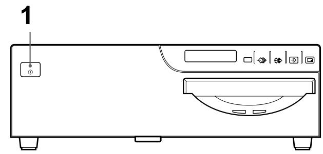
1 Turn on the video monitor and the printer.
2 Start the video source to display the source image on the video monitor. This operation is done using the controls of the video equipment acting as the source.
Shows that the image from the source equipment is displayed on the screen.
Continue to the next page
3 Press the CAPTURE button at the instant when the image you want to print appears on the screen.
The image is captured into memory. The memory image is displayed on the screen. Which image appears after this, the source image or the memory image, depends on the setting made with the FUNCTION SETUP function of the printer. (See page 42.)
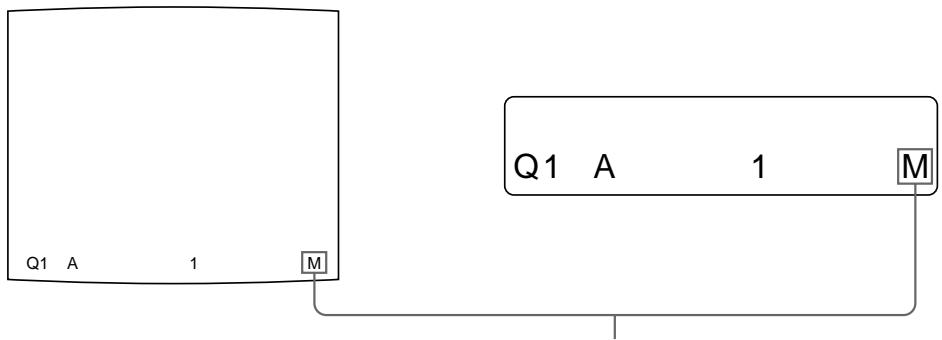
Shows that the image captured in memory is displayed on the monitor.
If the captured image is blurred
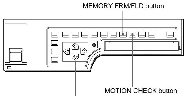
A quickly moving image may be blurred when captured. Should this occur, change the memory mode setting to FIELD, then print it again. Although the blur should be eliminated, the ultimate print quality will be slightly degraded. Select the FIELD mode by pressing the MEMORY FRM/FLD button. (See "Selecting the memory mode" on page 33.)
Notes
- Usually, it is recommended that you make printouts in FRAME mode. To confirm the memory mode setting, press the MEMORY FRM/FLD button. The currently selected memory mode appears lit in green on the video monitor and spelled out in the printer window display for about three seconds, then disappears.
- You can change the memory mode only when selecting 1 (full-size image), 2 (two-reduced images) or 4 (four-reduced images).
- The number of usable memory pages depends on the selected memory mode. (See page 38.)
To change the image captured in memory
① To display the source image when the memory image is displayed on the screen, press the SOURCE/MEMORY button.
② Press the CAPTURE button at the instant the image you want to print appears.
The previous image is replaced with the new one.
Note
If you turn off the power, the image stored in memory will be lost. Should this happen, capture the image into memory again after turning on the power. If no image is stored in memory, the printer will not print even if you press the PRINT button.
4 Press the PRINT button.
The printout pops out on the paper cover.
The printing time depends on the type of paper and printer settings.
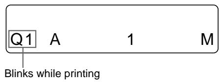
Changes as follows during printing:
Start printing yellow magenta cyan printing ends
The color which is currently being printed is displayed. This indication changes as printing progress.
Notes
- Do not turn off the power during printing.
If you do so, paper may not be ejected and may jam in the printer. - Do not pull the paper from the paper cover until printing has been completed.
- Do not leave more than 10 sheets of printouts on the paper cover. Doing so may cause a paper jam.
- You can not change the printer application mode or settings on the WINDOWSETUP menu during printing.
To stop printing
When you make one printout, you can not stop printing midway. Wait until a printout pops out on the paper cover.
When you make multiple copies, reset the printout quantity to 1 while the first copy is being printed. (See "Making Multiple Copies of Identical Printouts" on page 23.)
If the printer does not print
The printer will fail to print in the following cases:
- While an error message is displayed on the video monitor screen and printer window display.
— Proceed as described in "Error/Warning Messages" on page 129.
- When an image has not been stored in memory.
- Image data stored in memory is lost if you turn off the power. Capture the image into memory again, then press the PRINT button.
To make a printout at high speed
Set PRN SPEED to HIGH in the PRINTER SETUP menu. (See page 30.)
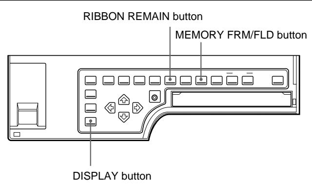
When you want to see an image that is hidden below a screen message
You can erase the screen message (such as Q1, A and so on) from the video monitor screen by pressing the DISPLAY button. The screen message disappears. To display a screen message, press the DISPLAY button again. (See “Erasing the Screen Display on the Video Monitor” on page 68.) You can also erase the information about ink ribbon and paper by pressing the RIBBON REMAIN button. (See “Displaying the Type and Remaining Amount of the Ink Ribbon” on page 69.)
If a black line appears on the printout
Sometimes, a black line appears on the printout, although it does not appear on the video monitor. This black line can be eliminated from the printout. (See "Changing the Printout Size/Printout Area" page 94.)
If the color quality of printouts is not satisfactory
You can obtain the satisfactory color quality of printout by compensating for the input signal and/or adjust the color quality of the printouts. (See “Compensating for the Input Signals” on page 78, and “Adjusting the Printout Color” on page 86.)
Notes
When storing your printouts:
- Avoid storing the printout in a location subject to high temperatures, high humidity, excessive dust or direct sunlight.
- Do not stick tape on a printout. Also, avoid leaving a plastic eraser on a printout or placing a printout in contact with materials which contain plasticizer (under a desk mat, for example).
- Do not allow alcohol or other volatile organic solvents to come into contact with the printouts.
Making Printouts with the Desired User Set Number
You can register all the printer settings as a user settings. The printer allows you to register three sets of settings as User Set 1, 2 and 3. (See "Registering a User Set" on page 116.) By selecting a desired user set number, the printer functions according to the corresponding settings. You can change a part of the selected user settings and make printouts.
Note
If you change the currently selected user set to another one, the image stored in memory pages will be cleared.
1 Turn on the video monitor and printer.
2 Start the video source to display the source image on the video monitor. This operation is done using the controls of the video equipment acting as the source.
3 Press the LOAD USER button. The currently selected user setting appears.
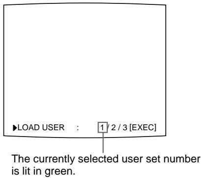
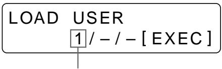
The currently selected user set number is displayed.
Continue to the next page
4 Select the user set number.
Press the LOAD USER button repeatedly until the desired user set turns green on the video monitor or until the desired user set is displayed on the printer window display.
Each time you press the LOAD USER button, the user set number changes in the order of 1 2 3 1 .
The selected user set number will disappear within about three seconds.
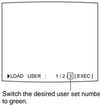
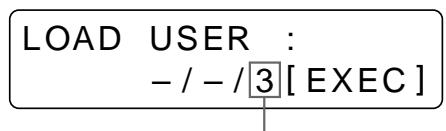
Display the desired user set number.
5 Press the EXEC button.
The user set selected in step 4 is executed.
While the selected user set is being executed, the following message appears.
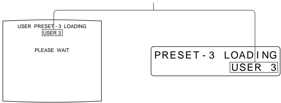
When the user name is registered, the user name appears.
6 Press the CAPTURE button at the instant the image you want to print appears on the screen.
The image is captured into memory.
7 Press the PRINT button.
The printer makes printouts according to the user set selected in step 4.
Making Multiple Copies of Identical Printouts
You can make up to 9 copies of identical printouts.
Setting the printout quantity
The following two methods are available to set the number of printouts.
- Using the PRINT QTY button. However, you cannot use the button to decrease the number of printouts.
- Using the menu
You can change the designated number of copies before printing or any time during printing.
To set the printout quantity by using the PRINT QTY button
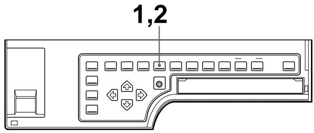
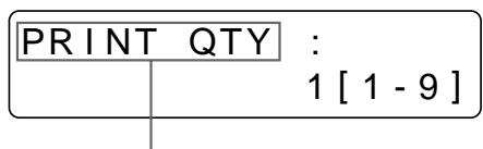
1 Press the PRINT QTY button.
The following screen appears.
If you do not perform any operation after you press the PRINT QTY button, the currently set number of copies appears for about 3 seconds, after which it disappears.
Currently selected number of copies
Continue to the next page
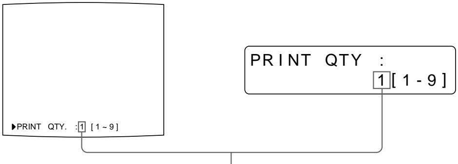
2 Press the PRINT QTY button until the desired number appears.
Repeatedly pressing the PRINT QTY button increases the number up to a maximum of 9. Or repeatedly pressing the button also increases the number up to a maximum of 9.
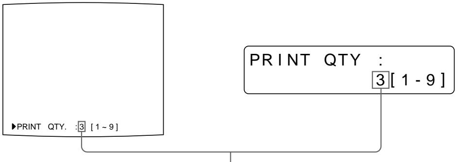
Press the PRINT QTY button or button until the desired number appears.
To decrease the number of copies
While the screen which appears in step 1 is being displayed, press the button.
Each time you press the button, the number decreases and stops at 1.
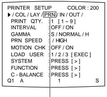
Setting the printout quantity using the menu
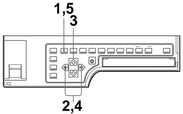
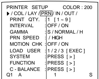
1 Press the MENU button.
The menu previously opened appears.
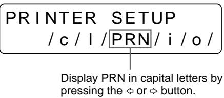
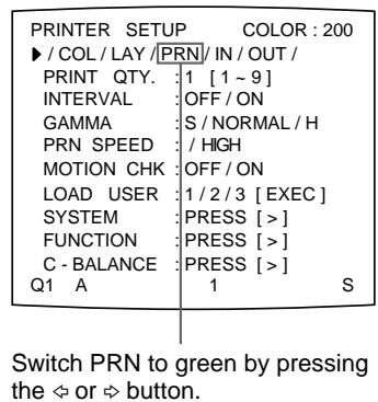
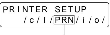
2 Select PRN by pressing the or button.
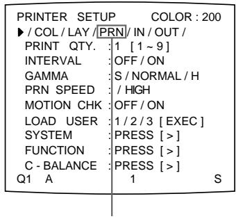
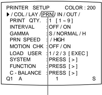
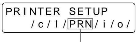
The PRINTER SETUP menu appears.
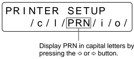
Switch PRN to green by pressing the or button.
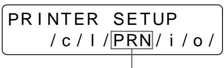
Display PRN in capital letters by pressing the or button.
3 Select PRINT QTY by pressing the or button.
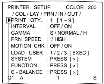
Press the 四 or 四 button until PRINT QTY appears.
Position the cursor at PRINT QTY by pressing the 四 or button.
4 Select the desired number of copies by pressing the or button.
| When you want to | Button |
| Increase the quantity. | ✕ |
| Decrease the quantity. | ✕ |
Press the MENU button. The regular screen appears.
If the paper runs out during printing
Load the paper into the paper tray and press the PRINT button.
However, the printout quantity is reset to the original quantity requested when printing is stopped.
For example, if the printout quantity is set to 5, and the paper runs out when three copies are printed, the printout quantity is reset to 5. If you want to print only the remaining copies, set the printout quantity to 2 after loading the paper. (See "Loading Paper" on page 12.)
Capturing Another Image While Printing
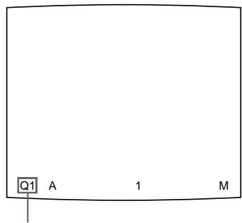
While the printer is printing, you can cue printing by capturing another image into another memory page to be printed once the printer becomes free. The usable memory pages depend on the type of printouts and settings. (See page 38.)
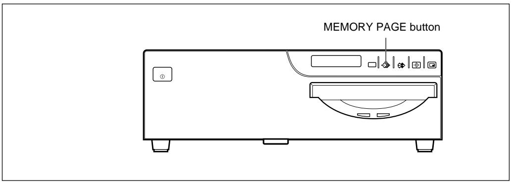
1 Select the desired memory page by pressing the MEMORY PAGE button. Pressing the MEMORY PAGE button switches the memory page.
The available memory pages appear in white.
2 Press the CAPTURE button at the instant the image you want to print appears on the screen.
3 Press the PRINT button. The image captured in step 2 is queued. The image is printed as soon as all previous printing jobs have been completed.
Memory page whose image has been queued for printing (blinks white on the video monitor)
The memory page display returns to white on the video monitor once printing has been completed.
Note
Another image cannot be stored in a memory page in which an image has already been queued for printing. In such a case, the “PLEASE WAIT PRINTING MEMORY” appears.
4 To queue another memory page, repeat steps 1, 2 and 3.
You can store various kinds of images in memory and make variations of printouts using the images captured in memory.
Variations of printouts that the printer can produce
The following variations of printout of the images stored in memory can be made.
Printout of a full-size image
Printout of two reduced images
Printout of four reduced images
Printout of eight reduced images
Printout of 16 reduced images
Printout of identical images a)
Printout with an insert
a) You can make printouts of two-, four-, eight or 16 identical reduced images.
You can make a printouts of multiple reduced images with white borders.
Also, you can make printouts of mirror images where images stored in the memory are rotated about the vertical axis.
Selecting the Printer Application Mode
The unit allows you to make printouts of a full-size image, two reduced images, four reduced images, eight reduced images and 16 reduced images.
Also by setting the printer application mode to either STANDARD or
DUPLICATE, you can make a printout of different multiple images or identical multiple images.
When you use the printer for the first time, the STANDARD application mode for full-size image printouts is selected.
Select the application mode according to what kind of printouts you want to make.
Note
Changing the application mode results in clearing images stored in all of the memory pages.
1 Press the MENU button.
The menu previously opened appears.
2 Select PRN by pressing the or button.
The PRINTER SETUP menu appears.
Switch PRN to green by pressing the or button.
Display PRN in capital letters by pressing the or button.
Continue to the next page
3 Select PRN SPEED by pressing the or button.
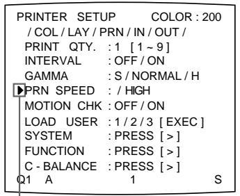
Position the cursor at PRN SPEED by pressing the or button.
When you use the UPC-540 Self Laminating Printing Pack, you can select the finish of the printouts. (See “Selecting the Lamination Pattern” on page 114.)
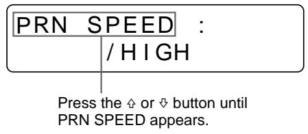
4 Select the desired PRN SPEED by pressing the or button.
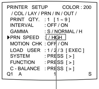
Switch the desired PRN SPEED to green by pressing the or button.
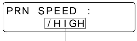
Display the desired PRN SPEED by pressing the or button.
| When you want to | PRN SPEED |
| Make a printout at normal speed. | NORMAL |
| Make a printout at high speed. | HIGH |
5 Select SYSTEM by pressing the or button.
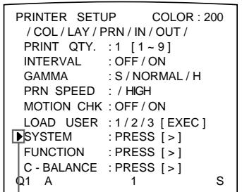
Position the cursor at SYSTEM by pressing the or button.
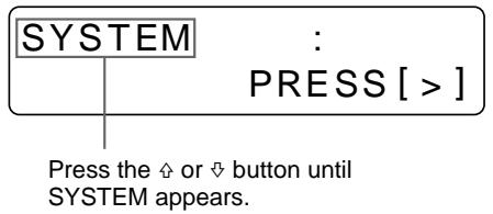
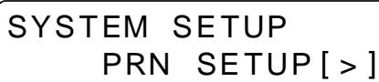
6 Press the button.
The SYSTEM SETUP menu appears.
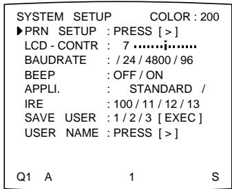
7 Select APPLI. by pressing the or button.
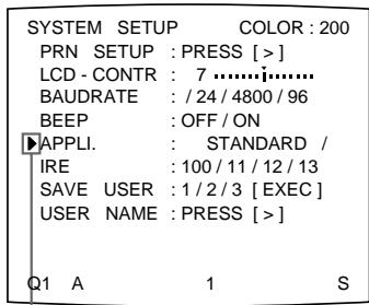
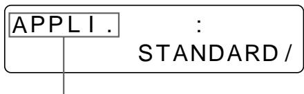
Press the or button until APPLI. appears.
Position the cursor at APPLI. by pressing the or button.
8 Select the desired application mode by pressing the or button.
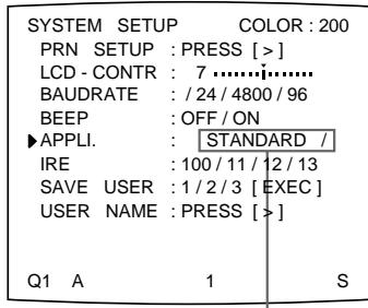
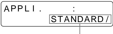
Display the desired mode in capital letters by pressing the or button.
Switch the desired mode to green by pressing the or button.
| Application mode | Printout |
| STANDARD | Printout with a full-size image, two different reduced images, four different reduced images, eight different reduced images and 16 different reduced images |
| DUPLICATE | Printouts of a full-size image, two identical reduced images, four identical reduced images, eight identical reduced images and 16 identical reduced images |
9 Select PRN SETUP by pressing the or button.
10 Press the button.
The PRINTER SETUP menu appears.
11 Press the MENU button.
The regular screen appears.
About the Memory
To make printouts, it is first necessary to capture the image in memory.
When capturing the image, there are two ways to use the memory, one is frame mode and the other is field mode.
Frame mode: A image is captured in a memory area.
Field mode: A memory area is divided into two, and images can be captured in each. A quickly moving subject can be printed with less blurring.
A memory area in which an image is captured is called a memory page in this manual.
The number of usable memory pages depends on the type of the reduced images selected and on the memory mode.
For detailed information, see "Selecting the memory page" on page 38.
Note
You can select the filed mode only when you select the full-image type of printout, two-reduced image printout or four-reduced image printout.
In frame mode
Video monitor
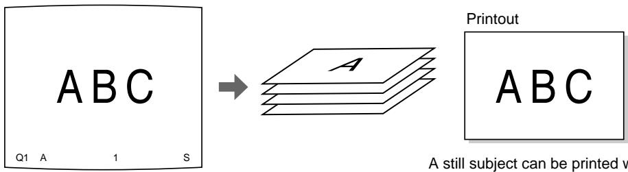
The image displayed in the video monitor is captured in memory page A.
A still subject can be printed with high resolution.
In field mode
Video monitor
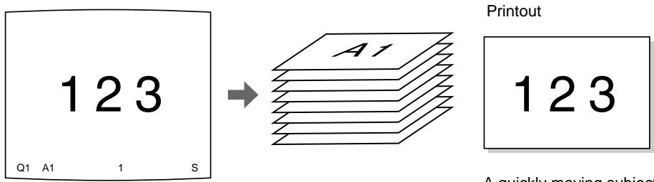
The image displayed in the video monitor is captured in memory page A1.
A quickly moving subject can be printed with less blurring.
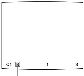
Selecting the memory mode
Note
You can select memory mode only when you select the full-image type of printout, two-reduced image printout or four-reduced image printout.
The following two methods are available to select the memory mode:
- Using the MEMORY FRM/FLD button
- Using the menu
To select the memory mode using the MEMORY FRM/FLD button
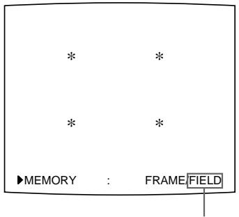
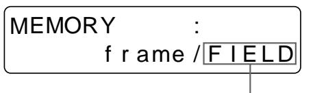
1 Press the MEMORY FRM/FLD button.
The following screen appears.
If you do not perform any operation after you press the MEMORY FRM/FLD button, the currently selected memory mode appears for about 3 seconds, after which it disappears.
The currently selected memory mode is lit in green

The currently selected memory mode is displayed in capital letters.
2 Select the desired memory mode by pressing the MEMORY FRM/FLD button. Press the MEMORY FRM/FLD button repeatedly until the color of the desired memory turns lit green on the video monitor, or until the desired memory mode is displayed in the capital letters on the printer window display.
Each time you press the FRM/FLD button, the memory mode changes.
FRAME: We recommend that, whenever possible, you print in this mode.
FIELD: Select this mode to reduce blurring when you print a quickly moving image.
To select the memory mode using the menu
1 Press the MENU button.
The previously selected menu appears.
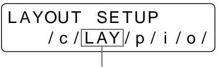
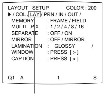
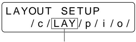
2 Select LAY by pressing the or button.
The LAYOUT SETUP menu appears.
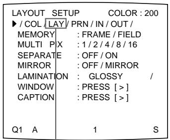
Switch LAY to green by pressing the or button.
3 Select MEMORY by pressing the or button.
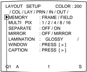
Position the cursor at MEMORY by pressing the or button.

Press the or button until MEMORY appears.
4 Select the desired memory mode by pressing the or button.
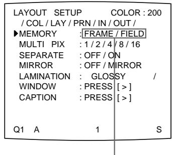
Switch the desired memory mode to green by pressing the or button.
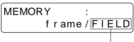
Display the desired memory mode in capital letters by pressing the or button.
5 Press the MENU button.
The regular screen appears.
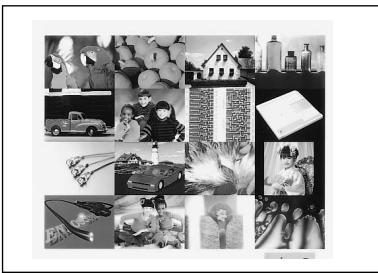
Making a Printout of Multiple Different Reduced Images
You can capture multiple images in a memory page and make a printout with those reduced images. This section explains how to make a printout with multiple reduced images.
A printout having multiple reduced images is made using the following the procedure below.
- Setting the printer application mode to STANDARD (See page 31.)
- Determining the number of reduced images. (See the following page.)
- Selecting the memory page (See page 38.)
- Selecting the method to be used to capture the images in memory (See page 40.)
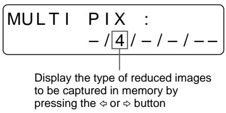
Selecting the number of reduced images to be captured in memory
The following two methods are available to select the memory mode:
- Using the MULTI PICTURE button
Using the menu
To select the desired type of reduced images to be captured in memory using the MULTI PICTURE button
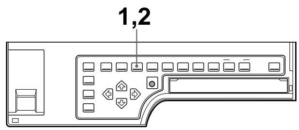
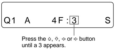
1 Press the MULTI PICTURE button.
The following screen appears.
If you do not perform any operation after you press the MULTI PICTURE button, the current setting appears for about 3 seconds, after which it disappears.
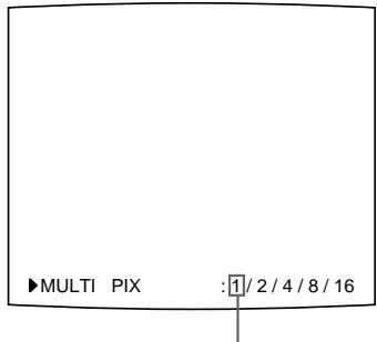
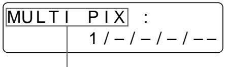
The currently selected type of reduced images to be captured in memory is displayed.
The currently selected type of reduced images to be captured in memory is lit in green.
2 Select the type of reduced images to be captured in memory by pressing the MULTI PICTURE button.
Press the MULTI PICTURE button repeatedly until the color of the type of reduced images to be captured in memory turns green on the video monitor, or until the type of reduced images to be captured in the memory is displayed on the printer window display.
Each time you press the MULTI PICTURE button, the type of reduced-image printout changes in order 1, 2, 4, 8, 16, 1....
| Type | Number of reduced images |
| 1 | 1 (Full-size image) |
| 2 | 2 (Two reduced images) |
| 4 | 4 (Four reduced images) |
| 8 | 8 (Eight reduced images) |
| 16 | 16 (16 reduced images) |
The screen is reset to the regular screen after a few seconds.
To select the type of reduced images to be captured in the memory using the menu
1 Press the MENU button.
The previously selected menu appears.
2 Select LAY by pressing the or button.
The LAYOUT SETUP menu appears.

Switch LAY to green by pressing the or button.
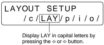
Display LAY in capital letters by pressing the or button.
3 Select MULTI pix by pressing the or button.
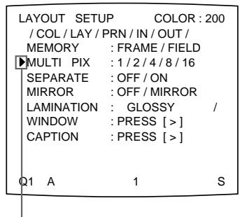
Position the cursor at MULTI PIN by pressing the or button.
Press the or button until MULTI_PIX appears.
Continue to the next page
4 Select the type of reduced images to be captured in memory by pressing the or button.
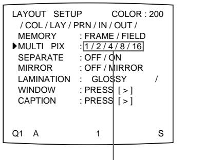
Switch the type of reduced images to be captured in memory to green by pressing the or button.
5 Press the MENU button.
The regular screen appears.
Selecting the memory page
The memory page used depends on the type of reduced images to be captured in memory and on the memory mode.
UP-50/51MD/51MDP
| Priter application mode | Type of reduced images to be captured in memory | Usable memory page | |
| FRAME | FIELD | ||
| STANDARD | Full image | A, B, C, D, E, F, G, H | A1, A2, B1, B2, C1, C2, D1, D2, E1, E2, F1, F2, G1, G2, H1, H2 |
| Two reduced images | A, B, C, D | A1, A2, B1, B2, C1, C2, D1, D2 | |
| Four reduced images | A, B | A1, A2, B1, B2 | |
| Eight reduced images | A, B, C, D | — | |
| 16 reduced images | A, B | — | |
| DUPLICATE | All types (1, 2, 4, 8 and 16) | A, B, C, D, E, F, G, H | A1, A2, B1, B2, C1, C2, D1, D2, E1, E2, F1, F2, G1, G2, H1, H2 |
UP-51MDU
| Priter application mode | Type of reduced images to be captured in memory | Usable memory page | |
| FRAME | FIELD | ||
| STANDARD | Full image | A, B, C, D | A1, A2, B1, B2, C1, C2, D1, D2 |
| Two reduced images | A, B | A1, A2, B1, B2 | |
| Four reduced images | A | A1, A2 | |
| Eight reduced images | A, B | — | |
| 16 reduced images | A | — | |
| DUPLICATE | All types (1, 2, 4, 8 and 16) | A, B, C, D | A1, A2, B1, B2, C1, C2, D1, D2 |
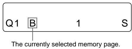
To select the memory page
Press the MEMORY PAGE button.

Press the MEMORY PAGE button repeatedly until the desired memory page appears.
Selecting the method to be used to capture the images
You can select the method to be used to capture the images by using the PRINTER SETUP menu and FUNCTION SETUP menu.
- Capturing only the image currently displayed on the video monitor screen or capturing images sequentially to all reduced-image positions of a memory page at regular intervals.
- Deciding which image displays on the video monitor screen after capturing an image, a memory image or a source image.
1 Press the MENU button.
The previously selected menu appears.
2 Select PRN by pressing the or button.
The PRINTER SETUP menu appears.
Switch PRN to green by pressing the or button.
When you select the type of reduced images to be captured, go to step 3.
When you select the type of full image to be captured, go to step 5
3 Select INTERVAL by pressing the or button.
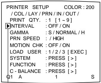
Position the cursor at INTERVAL by pressing the or button.
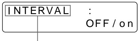
Press the or button until INTERVAL appears.
4 Select the desired method for capturing images by pressing the or button.
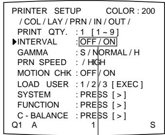
Switch the desired setting to green by pressing the or button.
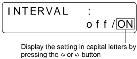
| When you want to | Setting |
| Capture only the image currently displayed on the video monitor screen by pressing the CAPTURE button. | OFF |
| Capture images sequentially to all positions of a memory page at regular intervals by pressing the CAPTURE button. | ON |
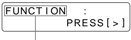
5 Select FUNCTION by pressing the or button.
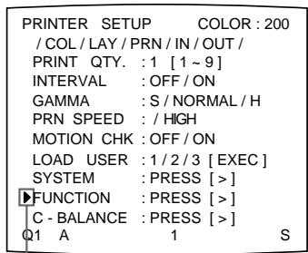
Position the cursor at FUNCTION by pressing the 念 or button.
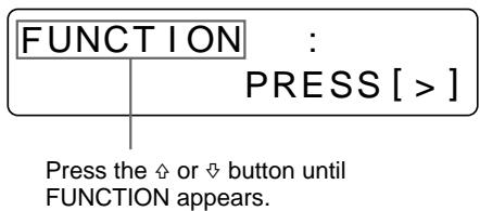
6 Press the button.
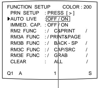
The FUNCTION SETUP menu appears.


Continue to the next page
7 Select AUTO LIVE by pressing the or button.
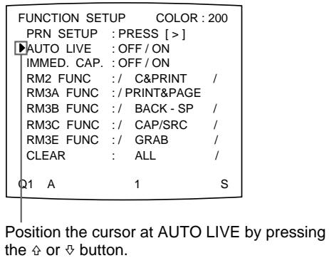
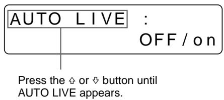
8 Select which image appears on the video monitor after the image is captured, by pressing the or button.
Switch the desired setting to green by pressing the or button.
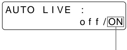
Display the setting in capital letters by pressing the or button
| When | Setting |
| The image captured in memory appears just after the printer captures the image, and the memory image remains on the video monitor screen. | OFF |
| The image captured in memory appears just after the printer captures the image, then after a few seconds, the source memory appears, whenever you press the CAPTURE button. | ON |
9 Press the MENU button.
The regular screen appears.
To return to the PRINTER SETUP menu
In step 9, position the cursor at PRN SETUP and press the button.
The PRINTER SETUP menu appears again.
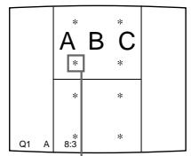
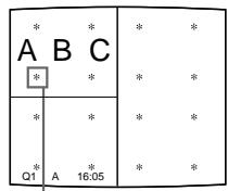
Making a Printout with multiple reduced images
This subsection explains how to make printouts of multiple reduced images taking, as an example, the making of a printout of four reduced images.
Before making the printout of four reduced images
- Confirm the printout color quality (using, for example, the LOAD COLOR number). (See page 86.)
- Select the type of four-reduced image to be captured in memory. (See page 36.)
- Select the appropriate memory page. (See page 38.)
- Set the method to be used to capture images in the memory page and select which image will appear after the image has been captured into memory, the memory image or the source image. (See page 40.)
- Select whether the white borders are to be added. (See page 49.)
You can select whether the white borders are added before or after capturing the four reduced images in the memory.
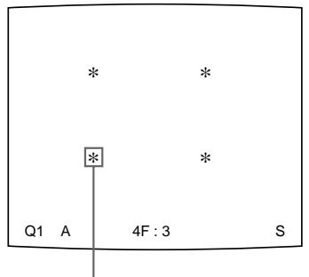
, , and buttons
1 Start the video source.
This operation is done using the controls of the video equipment acting as the source.
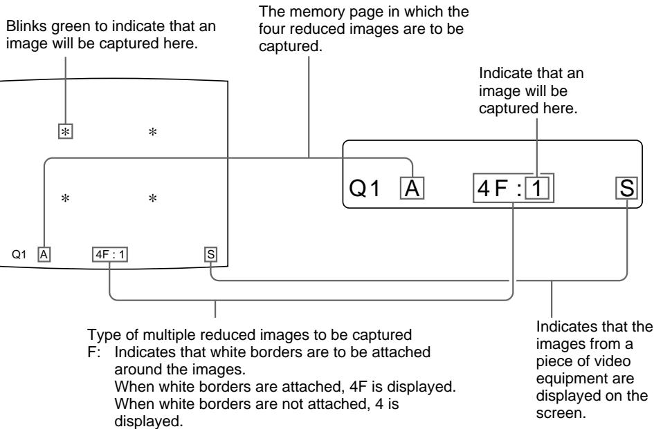
1: Indicate that an image will be captured here.
2 Press the CAPTURE button at the instant the image you want to print appears on the screen.
The image has been captured in the location indicated by the green blinking star on the video monitor screen or the position number displayed on the printer window display in step 1. The green blinking star (referred to as the cursor) on the monitor video moves to the next position and the number on the printer window display advances by 1.
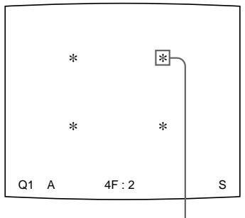
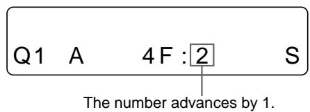
The blinking cursor moves to the next position.
At this time, the image captured in memory is displayed on the video monitor screen. However, the image to be displayed after a few seconds depends on the setting of AUTO LIVE in the FUNCTION SETUP menu. (See page 42.)
When INTERVAL in the PRINTER SETUP menu is set to ON, the image is automatically captured sequentially to four positions at regular intervals. In this case, go to step 5.
When the source image is displayed at the position where the next image is to be captured, go to step 4.
3 Press the SOURCE/MEMORY button.
The source image appears on the video monitor screen.
4 Repeat steps 2 and 3 until you have captured four images when the memory image remains on the video monitor screen.
Repeat step 2 until you have captured four images when the source image appears on the video monitor screen at the next position where the image is to be captured.
To replace a captured image
When INTERVAL is set to OFF in the PRINTER SETUP menu, you can replace a captured image.
Example: When you want to change the image stored in the third position.
① Select the third position where the image which you want to replace is located by pressing the , , or button.
Pressing the , , or button moves the cursor one position by one position vertically or horizontally.
Press the , , or button until the third cursor blinks green.
② Display the source image on the video monitor.
(3) Press the CAPTURE button at the instant the image you want to print appears.
The previously stored image is replaced with the newly stored image.
To skip a previously captured image
When an image has already been captured, the previously captured image can be replaced by pressing the CAPTURE button.
Skip images that you want to keep by pressing the , , or button.
5 Press the PRINT button.
The four reduced images are printed on one sheet of paper.
Whether white borders are attached depends on the setting of SEPARATE in the LAYOUT SETUP menu. (See page 49.)
If the printout is blurred
When you make a printout of a full image, or two or four reduced images captured in memory in FRAME mode, the images on a printout may be blurred. Should this occur, change the memory mode setting to FIELD, then print it again. Although the blur should be eliminated, the ultimate print quality will be slightly degraded. Select the FIELD mode by pressing the MEMORY FRM/FLD button. (See "Selecting the memory mode" on page 33.)
Switch FIELD to green.
Display FIELD in capital letters.
Notes
- This function is available only when one of either full image, or two or four reduced images is selected to be captured in memory.
- Usually, it is recommended that you make printouts in FRAME mode. To confirm the memory mode setting, press the MEMORY FRM/FLD button. The currently selected memory mode appears for about three seconds, then disappears.
To confirm whether the captured images are blurred on the video monitor
You can check whether the full image, or the two or four reduced images captured in memory are blurred on the video monitor.
When you select full image: You can check whether the captured image is blurred by displaying the memory image on the video monitor.
When you select two or four reduced images to be captured: Press the MOTION CHECK button to set the MOTION CHECK function to ON. You can check whether the reduced images captured in memory are blurred on the video monitor. In this case, the image on the video monitor will be slightly degraded.
Note
The MOTION CHECK function is available only for the images displayed on the video monitor. To eliminate blur from the printout, change the memory mode setting to FIELD. (See "If the printout is blurred" on this page.)
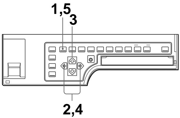
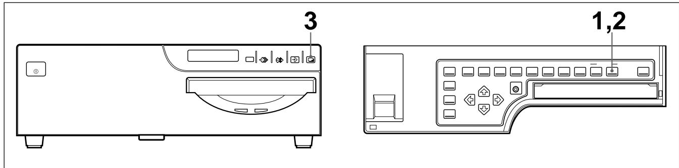
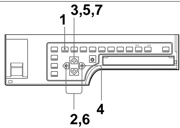
To set the MOTION CHECK function using the MOTION CHECK button
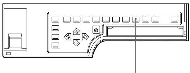
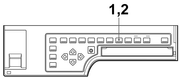
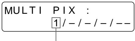
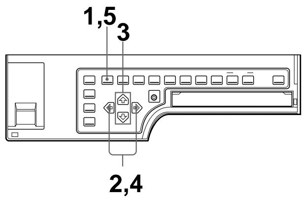
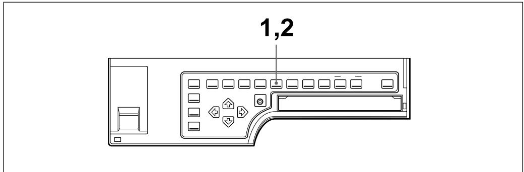
1,2
1 Press the MOTION CHECK button.
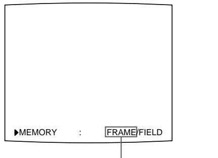
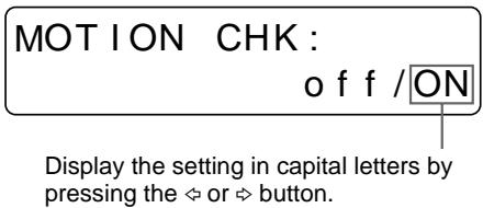
The following screen appears.
If you do not perform any operation after you press the MOTION CHECK button, the currently selected setting appears for about 3 seconds, after which it disappears.
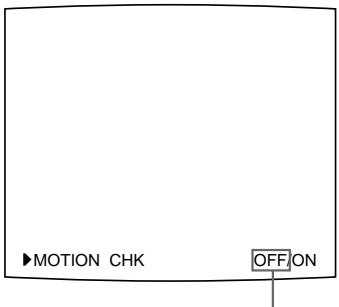
The currently selected setting is lit in green
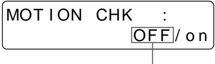
The currently selected setting is displayed in capital letters.
2 Select the desired setting by pressing the MOTION CHECK button.
Press the MOTION CHECK button repeatedly until the color of the desired setting turns green on the video monitor, or until the desired setting is displayed in capital letters on the printer window display.
Each time you press the MOTION CHECK button, the setting changes.
| When you want to | Setting |
| See the letters or fine images on the video monitor. | OFF |
| Confirm whether the two or four reduced images captured in the memory are blurred | ON |
The screen is reset to the regular screen after a few seconds.
Note
Even if you change the setting of the MOTION CHECK function, the printout quality will not be affected.
To select the setting using the menu
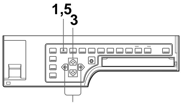
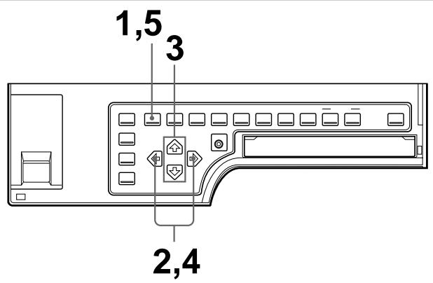
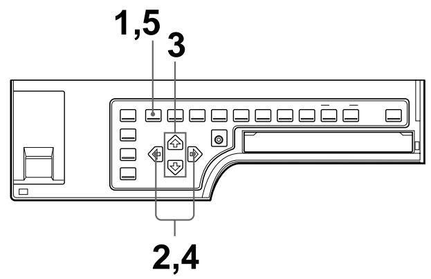
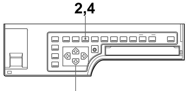
2,4
1 Press the MENU button.
The previously selected menu appears.
2 Select PRN by pressing the or button.
The PRINTER SETUP menu appears.
Switch PRN to green by pressing the or button.
3 Select MOTION CHK by pressing the or button.
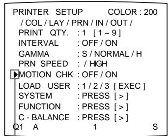
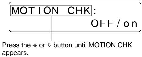
Position the cursor at MOTION CHK by pressing the 口 or 口 button.
4 Select the desired setting by pressing the or button.
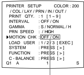
Switch the desired setting to green by pressing the or button.
5 Press the MENU button.
The regular screen appears.
Making a printout with white borders
The unit allows you to decide whether or not the images are printed with white borders.
1 Press the MENU button.
The previously selected menu appears.
2 Select LAY by pressing the or button.
The LAYOUT SETUP menu appears.
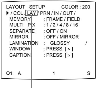
Switch LAY to green by pressing the or button.

Display LAY in capital letters by pressing the or button.
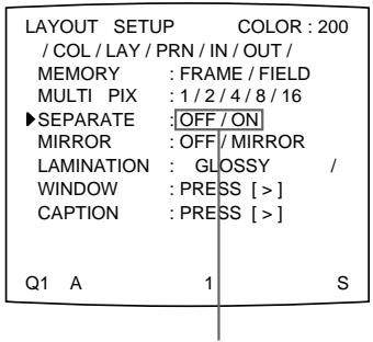
3 Select SEPARATE by pressing the or button.
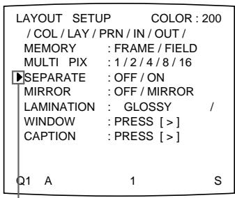
Position the cursor at SEPARATE by pressing the or button.
Press the or button until SEPARATE appears.
Continue to the next page
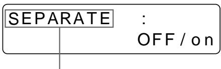
4 Select whether the images are printed with or without white borders by pressing the or button.
Switch the desired setting to green by pressing the or button.
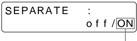
Display the setting in capital letters by pressing the or button.
| When you want to | Setting |
| Print the images without white borders. | OFF |
| Print the images with white borders. | ON |
Press the MENU button. The regular screen appears.
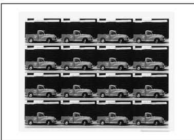
Making a Printout of Identical Reduced Images
You can make a printout of identical reduced images.
Before making the printout of identical reduced images
- Set the printer application mode to Duplicatedate. (See page 31.)
- Select the desired type of the identical reduced images to be captured in memory. (See page 36.)
- Select the appropriate memory page. (See page 38.)
- Select whether the white borders are to be added. (See page 49.)
You can select whether white borders are added before or after capturing the four reduced images in memory.
1 Start the video source.
This operation is done using the controls of the video equipment acting as the source.
2 Press the CAPTURE button at the instant the image you want to print appears on the screen.
The image captured in the memory appears on the whole screen. (The image is displayed in full size.)
To change the image in memory
① Start the video source.
(2) Press the CAPTURE button at the instant the image you want to print appears.
The previously captured image is replaced with the newly captured image.
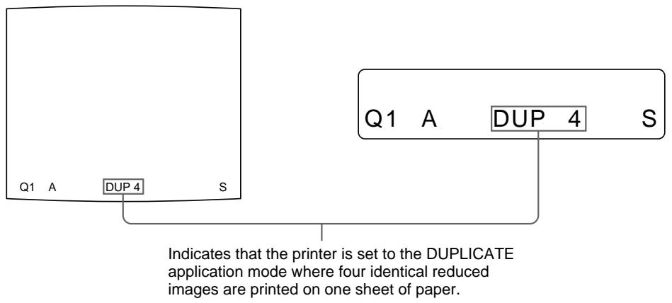
3 Press the PRINT button.
The identical reduced images are printed on one sheet of paper.
Making a Printout with an Insert
You can make printouts with an insert which is a reduced image.
Either eight or 16 reduced images to be captured are used for deciding the image to be inserted onto the full image. However, the position and the size of the reduced image to be inserted are those for the four reduced images.
3
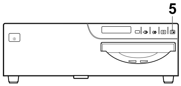
1 Display the full-size image stored in memory by pressing the SOURCE/ MEMORY button. Or capture the full-size image in memory. (Follow steps 1 to 3 of "Making Full-Size Image Printouts" on page 17.)
2 Press the MULTI PICTURE button repeatedly until either the 8 or 16 reduced-image type (without white borders and in STANDARD printer application mode) is selected.
(See “Selecting the number of reduced images to be captured in memory” on page 36.)
3 Capture the image to be inserted.
① Select the position where the reduced image is to be inserted by pressing the , , or button.
Example: To insert the image in the lower-left position
When you select 8 in step 2
Position the cursor (blinking) to this position by pressing the , or button.

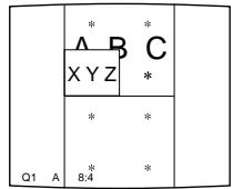
Image which appears after the CAPTURE button is pressed in step ②.
When you select 16 in step 2
Position the cursor (blinking) at this position by pressing the , , or button.

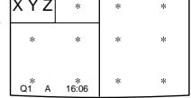
The image which appears after the CAPTURE button is pressed in step ②.
② Press the CAPTURE button at the instant the image you want to insert appears.
The image to be inserted is captured at the position selected in step ①.
4 Press the MULTI PICTURE button to reset the printer to the type of full-size image to be captured.
The full-size image with an insert appears on the video monitor.
5 Press the PRINT button.
The image with an insert is printed.
Making a Printout of Mirror Images
You can set the printer so that images captured in the memory are rotated about the vertical axis (mirror images) and make a printout of these mirror images.
1 Press the MENU button.
The previously selected menu appears.
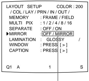
2 Select LAY by pressing the or button.
The LAYOUT SETUP menu appears.
Switch LAY to green by pressing the or button.
Display LAY in capital letters by pressing the or button.
Continue to the next page
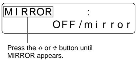
3 Select MIRROR by pressing the or button.
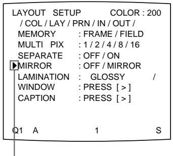
Position the cursor at MIRROR by pressing the or button.
4 Select whether the captured images are to be rotated or not.
Switch the desired setting to green by pressing the or button.
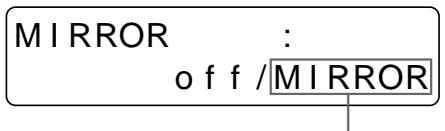
Display the setting in capital letters by pressing the or button.
| When you want to | Setting |
| Print the images in the normal direction. | OFF |
| Rotate the images about the vertical axis. | MIRROR |
5 Press the MENU button.
The regular screen appears.
Note
Even if you set MIRROR to MIRROR, a caption entered in the CAPTION window will be printed in the normal direction.
A caption, such as data or comments, can be added to a printout below the image.
You can input up to 80 characters. When using a computer via the RS-232C
interface, you can input up to 160 characters on two lines from the computer.
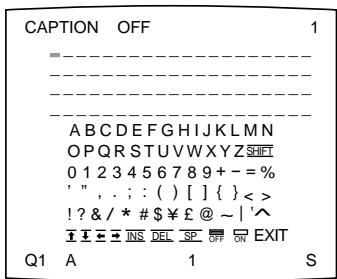
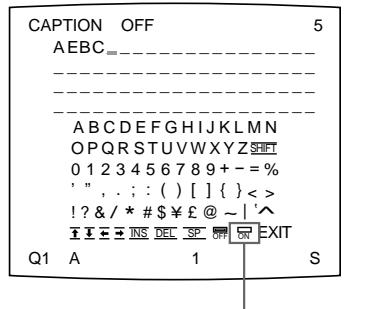
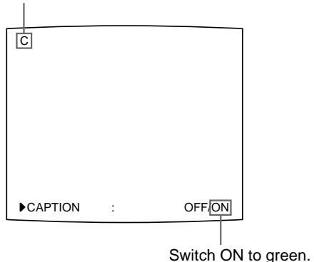
About the CAPTION menu
A caption is entered from the CAPTION menu. You can input a caption in any printer application mode and make a printout with that caption.
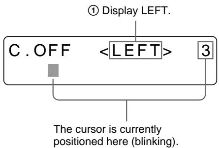
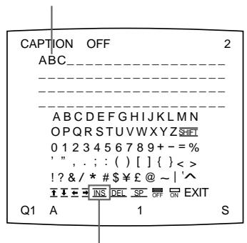
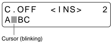
A brief explanation of each item of the CAPTION menu is given below.
Character display area
The cursor lit in green indicates
the position where a character can
be entered.
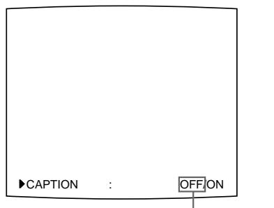
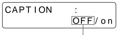
The entered characters are displayed here.
ON: displayed when printing with a caption.
OFF: displayed when printing without
a caption (OFF is displayed as the factory-setting).
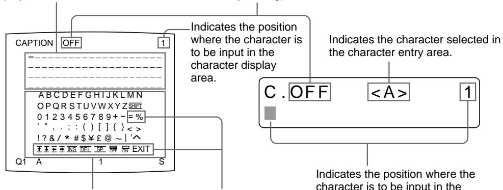
Character entry area
The character or symbol where
the cursor is located is highlighted
in green and this highlighted
character is to be entered.
Symbols and words
can be used to enter a
Indicates the position where the
character is to be input in the
character display area.
Symbols and words can be used to enter a caption
Display in the
CAPTION menu Function
INS Inserts one character without erasing the highlighted character.
DEL Deletes a highlighted character and characters shift back by one.
SP Puts one space at the position of the highlighted character by erasing that character. One space is left.
OFF Selects printing without a caption.
ON Selects printing with a caption.
EXIT Returns from the CAPTION menu to the LAYOUT SETUP menu.
SHIFT Selects either capital letters or small letters.
Displaying the CAPTION Menu
The following two methods are available to display the CAPTION menu:
- Using the CAPTION INPUT button
Using the menu
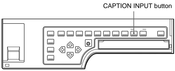
Press the CAPTION INPUT button.
The CAPTION menu appears.

To display the CAPTION menu by using the LAYOUT SETUP menu
Position the cursor at CAPTION on the LAYOUT SETUP menu by pressing the or button, the press the button.
The CAPTION menu appears.
Entering a Caption
Enter a caption as follows. The setting remains effective until you enter a new setting - even if you turn the power off.
Notes
- If you turn off the power of the printer without returning to the LAYOUT SETUP menu or the regular screen after entering the characters in the CAPTION menu, the entered characters are cleared.
- During printing, you cannot enter or edit the caption in the CAPTION menu.
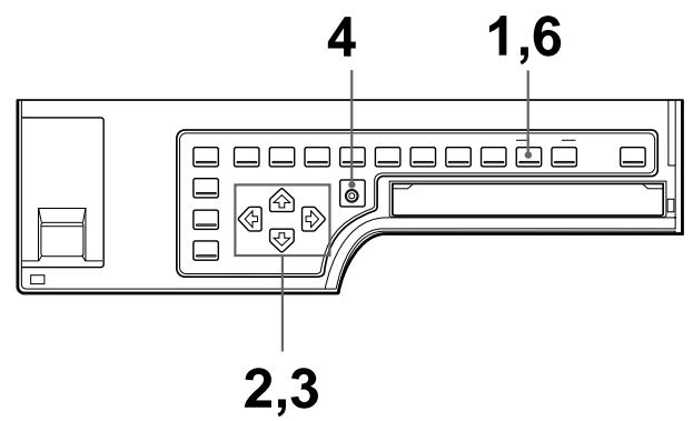
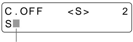
1 Press the CAPTION INPUT button. The CAPTION menu appears.
2 Position the cursor (the line lit in green) at the point where you want to enter the character in the character display area.
To move the cursor
① Select the arrow corresponding to the direction in which you want to move the green cursor in the character display area, by pressing the , , or button.
② Press the EXEC button. Each time you press the EXEC button, the cursor moves one position in the designated direction.
Example: Move the cursor to the left by two.
The cursor is currently positioned here (lit in green).
① Highlight the button in green.
② Press the EXEC button twice.
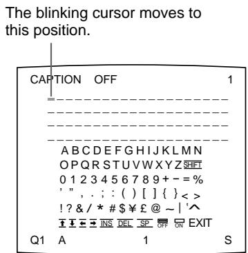

The cursor moves to this position.
Note
When OFF is displayed, the CAPTION input mode is set to off. Thus, you cannot add a caption to the printouts. (See "Making printouts with a caption" on page 63.)
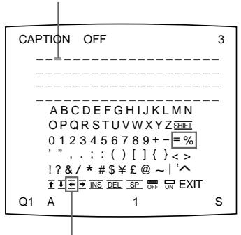
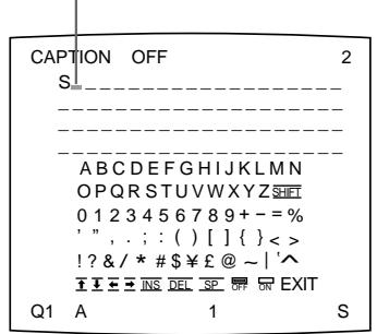
3 Select the character you want to enter by pressing the , , or button.
Example: Enter S.
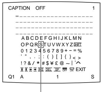
Highlight S in green by pressing the , , or button. S blinks in green.
Display S by pressing the , , or button.
To select either capital letters or small letters
You can change the characters in the character entry area from the capital letters to small letters or vice versa.
① Highlight SHIFT in green by pressing the , , or button on the video monitor.
When characters are displayed in capital letters in the character entry area, SHIFT is displayed in the printer window display. When displayed in lower-case letters, shift is displayed.
② Press the EXEC button.
Capital letters are changed to small letters, or small letters are changed to capital letters in the character entry area.
Note
Characters already entered (displayed in the character display area) are not changed even if letters are changed in the character entry area.
4 Press the EXEC button.
The character selected in step 3 appears at the point where the green cursor is positioned in the character display area, after which the cursor moves to the next position.
The cursor moves to this position.
The cursor moves to this position.
When you enter the wrong character in the above example
① Select by pressing the , , or button, then press the EXEC button. The cursor moves back by one and the character entered in step 3 is highlighted in green.
② Select DEL by pressing the , , or button.
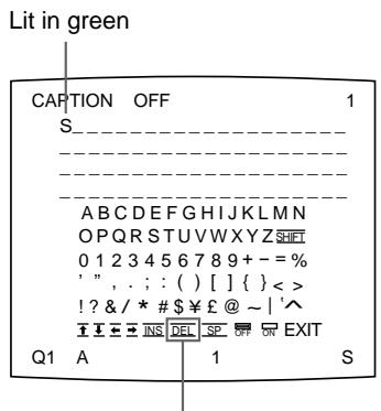
Highlight DEL in green by pressing the , , or button. DEL blinks in green.
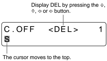
③ Press the EXEC button.
The character selected in ① is deleted.
When the character to be deleted is placed among entered characters, the characters after the deleted one shift back by one.
Note
After the EXEC button is pressed, the monitor screen may become dark for a moment.
5 Repeat steps 2, 3 and 4 to enter the remaining characters of the caption.
To enter a space
① Position the green cursor at the point where you want to enter a space.
② Select SP by pressing the , , or button.
③ Press the EXEC button.
A single space is entered and the green cursor moves to the next position. If there is a character at the position where the space is entered, that character is deleted and a single space is left.
To replace a previously entered character without changing the number of characters
You can replace a previously entered character with a new one.
① Position the green cursor at the character to be replaced by performing the operations explained in step 2.
(2) Overwrite the invalid character with the correct character by performing the operations explained in steps 3 and 4.
The previously entered character is replaced with the new one.
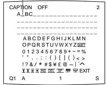
To add characters midway
① Position the cursor at the position where a character is to be added by performing the operations explained in step 2.
② Select INS by pressing the , , or button. Then press the EXEC button.
A single space is inserted between characters and the cursor is positioned at the space.
Example: Add a character between A and B.
① Move the cursor at B. (B is highlighted in green).
② Highlight INS. (INS blinks in green.) Then, press the EXEC button.
② Display INS. Then, press the EXEC button.
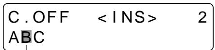
① Move the cursor at B.
B blinks when the cursor comes to B.
A single space is inserted between A and B and the green cursor is positioned at the space.
Cursor (lit green)
Note
After the EXEC button is pressed, the monitor screen may become dark for a moment.
③ Enter the character to be added.
6 Press the CAPTION INPUT button.
The entered characters are stored in memory.
The regular screen appears.
Or, you can return to the regular screen using the following method:
6 Highlight EXIT by pressing the , , or button, then press the EXEC button.
The entered characters are stored in memory.
The LAYOUT SETUP menu appears.
7 Press the MENU button.
Note
If you turn off the printer before performing the operation in step 6, characters entered in steps 2, 3, 4 and 5 are cleared without being stored in memory.
To make printouts with a caption
The CAPTION menu allows you to set whether a caption is attached or not to a printout.
Perform the following in step 6 before pressing the CAPTION INPUT button:
① Select ON by pressing the , , or button.
Highlight ON by pressing the , or button. ON blinks in green.
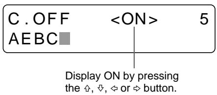
Select OFF to make printouts without a caption.
② Press the EXEC button.
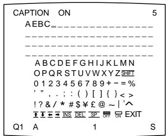
After this, all printouts are made with a caption.
You can also decide whether to make printouts with a caption by using the CAPTION ON/OFF button, before attempting to print.
Making printouts with a caption
Store a caption that you want to attach to the printout beforehand.
(See "Entering a Caption" on page 57.)
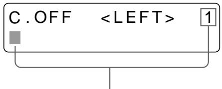
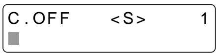
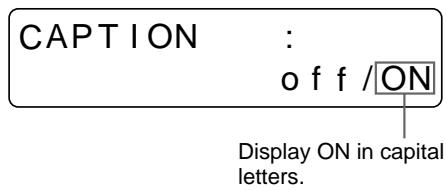
1 Press the CAPTION ON/OFF button.
The current setting appears. The video monitor screen is reset to the regular screen after a few seconds.
The currently selected setting is lit in green
The currently selected setting is displayed in capital letters.
2 Select ON.
Press the CAPTION ON/OFF button repeatedly until the color of ON turns green on the video monitor, or until ON is displayed in capital letters on the printer window display.
Each time you press the CAPTION ON/OFF button, the setting changes in the order ON OFF ON....
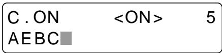
When the CAPTION ON/OFF button is set to ON, C appears
To make a printout without a caption
Select OFF.
3 Press the PRINT button.
The printout with a caption is made.
You can delete images captured to memory pages, from either all of the memory pages or a single memory page, by using the CLEAR button.
Whether the images of all memory pages or only a single memory page are deleted depends on the setting of CLEAR in the FUNCTION SETUP menu.
Setting the Function of the CLEAR Button
1 Press the MENU button.
The previously selected menu appears.
2 Select PRN by pressing the or button.
The PRINTER SETUP menu appears.
Display PRN in capital letters by pressing the or button.
3 Select FUNCTION by pressing the or button.
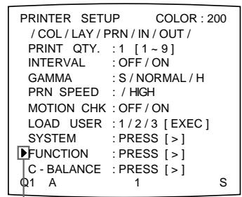
Position the cursor at FUNCTION by pressing the 念 or button.
Press the or button until FUNCTION appears.
4 Press the button.
The FUNCTION SETUP menu appears.
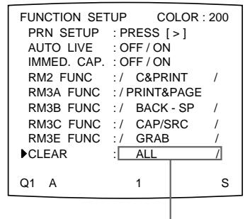
| FUNCTION SETUP COLOR:200 | ||
| ▶PRN SETUP : PRESS [>] | ||
| AUTO LIVE : OFF / ON | ||
| IMMED. CAP : OFF / ON | ||
| RM2 FUNC : / C&PRINT / | ||
| RM3A FUNC : / PRINT&PAGE | ||
| RM3B FUNC : / BACK - SP / | ||
| RM3C FUNC : / CAP/SRC / | ||
| RM3E FUNC : / GRAB / | ||
| CLEAR : ALL / | ||
| Q1 A 1 S |
FUNCTION SETUP PRN SETUP[>]
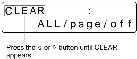
5 Select CLEAR by pressing the or button.
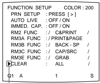
Position the cursor at CLEAR by pressing the or button.
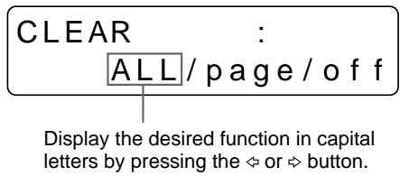
6 Select the function of the CLEAR button by pressing the or button.
| When you want to | Settings |
| Delete images of all memory pages. | ALL |
| Delete images of a single memory page. | PAGE |
| Deactivate the CLEAR button. | OFF |
Switch the desired function to green by pressing the or button.
7 Select PRN SETUP by pressing the or button. Then, press the button. The PRINTER SETUP menu appears.
Once you set the function of the CLEAR button, the CLEAR button functions according to the setting until the function setting is changed.
To return to the regular screen
Press the MENU button.
Deleting Images Stored in Memory
Note
You cannot restore images once they have been deleted.
Deleting images in all memory pages simultaneously
Before deleting images in all memory pages
Set CLEAR to ALL in the FUNCTION SETUP menu.
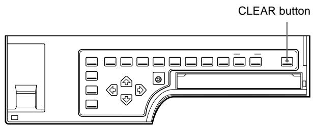
Press the CLEAR button.
All images stored in the printer are cleared.
Note
Even if you press the CLEAR button when the source image is displayed on the video monitor, the memory image appears without deleting images in the memory pages. In this case, press the CLEAR button again. All images stored in the printer are cleared.
Deleting images in a certain memory page
Before deleting images
Set CLEAR to PAGE in the FUNCTION SETUP menu.
1 Press the SOURCE/MEMORY button when the source image is displayed on the video monitor screen.
The image stored in memory is displayed on the screen.
2 Select the memory page from which images are to be deleted by pressing the MEMORY PAGE button.
3 Press the CLEAR button.
The image in the memory page selected in step 2 is deleted.
You can erase or display characters displayed on the video monitor (Q1, A and so on) and information about the ink ribbon.
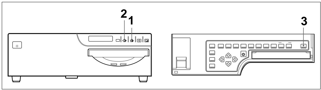
Erasing the Screen Display on the Video Monitor
You can erase characters displayed on the video monitor when, for example, it is hard to see the image that is hidden behind the screen display. The printer operation is the same, regardless of whether those images are displayed on the video monitor. Since the same message are displayed in the printer window display, perform operations watching these messages in the printer window display.
1,2
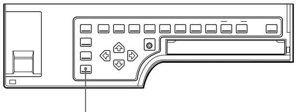
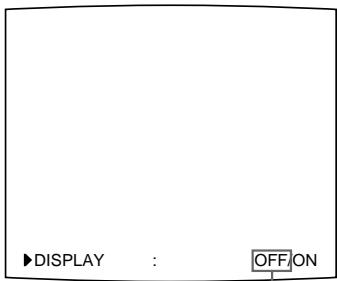
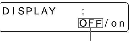
1 Press the DISPLAY button.
The current setting appears. The video monitor screen is reset to the regular screen after a few seconds.
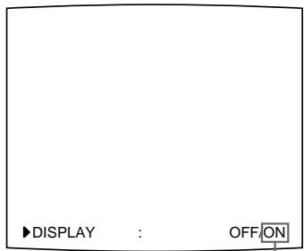
The currently selected setting is lit in green
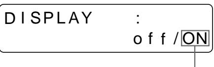
The currently selected setting is displayed in capital letters.
2 Select OFF.
Press the DISPLAY button repeatedly until the color of OFF turns green on the video monitor, or until OFF is displayed in capital letters in the printer window display.
Each time you press the DISPLAY button, the setting changes in the order ON
OFF ON....
Switch OFF to green.
Display OFF in capital letters.
To display characters on the video monitor
Select ON.
To perform the setting for the monitor display on the menu
You can also set whether characters are displayed on the video monitor by changing DISPLAY to ON or OFF in the OUTPUT SETUP menu. The setting of the DISPLAY button also changes according to the setting of DISPLAY in the OUTPUT SETUP menu, and vice versa.
When you want to see an image that is hedden below a menu
You can erase the menu temporarily while holding the DISPLAY button down.
Note
The error messages are always displayed regardless of the setting of the monitor display.
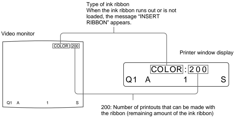
Displaying the Type and Remaining Amount of the Ink Ribbon
You can always display the type of the ink ribbon and its remaining amount on the video monitor.
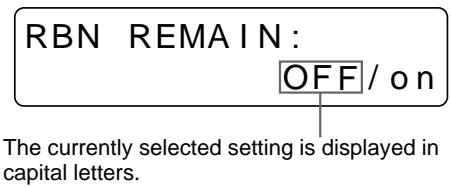
1 Press the RIBBON REMAIN button.
The current setting appears. The video monitor screen is reset to the regular screen after a few seconds.
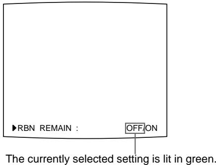
Continue to the next page
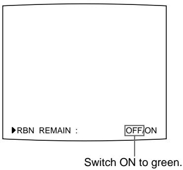
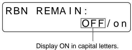
2 Select ON.
Press the RIBBON REMAIN button repeatedly until the color of ON turns green on the video monitor, or until ON is displayed in capital letters on the printer window display.
Each time you press the RIBBON REMAIN button, the setting changes in the order ON OFF ON....
To erase the information about the ink ribbon
Select OFF.
Note
Use the ribbon remain display as a criterion. The correct amount remaining of the ink ribbon may not be displayed.
To perform the setting for the display of ink ribbon information using the menu
You can also set whether the type of ink ribbon and its remaining amount are displayed on the video monitor by changing RBN REMAIN to ON or OFF in the OUTPUT SETUP menu. The setting of the RIBBON REMAIN button also changes according to the setting of RBN REMAIN in the OUTPUT SETUP menu, and vice versa.
The printer is packed together with the following accessories. Check that nothing is missing from your package.
Ink ribbon holder (1)

AC power cord (1)
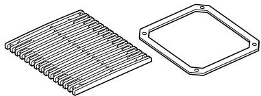
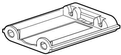
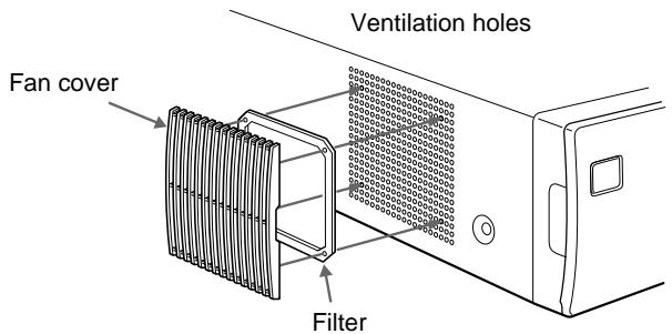
Fan cover with a filter (1)
Fan cover
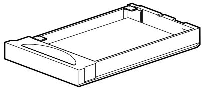
Paper tray (1)
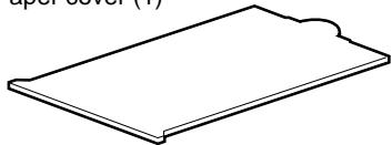
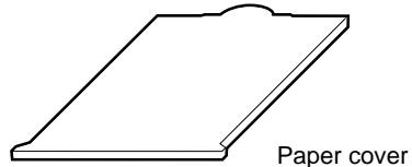
Paper cover (1)
Color printing pack a) (1)
Thermal head cleaning kit (1)
Warranty card (1) (for US and
Canadian model only)
Instructions For Use (1)
a) Use the ink ribbon cartridge and paper for an operation check.
Notes
- Retain the original carton and packing materials in case you have to transport the unit in the future.
- Remove the ink ribbon cartridge and paper tray when transporting the printer.
- When transporting the printer, secure the thermal head. (For detailed information on how to secure, see page 121.)
Assembly
To attach the paper cover, paper tray and ink ribbon cartridge
For details of how to assemble them, see the pages given in parentheses.
Paper tray (page 12)
Ink ribbon holder (page 9) Attach the ink ribbon cartridge after loading the ink ribbon into the ink ribbon holder.
To attach the fan cover and the filter
Attach the filter to the fan cover, then mount them on the left side of the printer.
Preparing the Remote Control Unit
The following remote control units (not supplied) allow you to control the printer remotely.
- RM-5500 Remote Control Unit: Used to connect to the REMOTE 1 connector
- RM-91 Remote Control Unit and FS-36 Foot switch: Used to connect to the REMOTE 2 connector.
- FS-30 Foot switch: Used to connect to the REMOTE 3 connector.
Using the RM-5500 remote control unit
The RM-5500 Remote Control Unit can be used either as a wireless or wired type. The buttons on the remote control unit duplicate those on the front panel of the printer. (See "Main Panel" on page 135 and "Sub Panel" on page 136.)
You can use the remote control unit's buttons which have the same names as those on the printer.
To use the RM-5500 remote control unit (not supplied) as a wireless unit
When using the remote control unit as a wireless unit, aim the head of the remote control unit at the remote sensor on the printer. With fresh batteries, the range of the remote control unit is about 3 meters.
Using the RM-91/FS-30/FS-36
The operations to be remotely controlled by the RM-91 remote control unit or the FS-30 foot switch depend on the remote operation settings made with the FUNCTION SETUP menu. ("Selecting the Operating Mode for Automatic Printing Capabilities" on page 104.)
FS-36 (not supplied) has three switches that have different functions. For detailed information on how to use those switches, refer to the manual supplied with the FS-36.
To enable printing, video equipment to act as an input signal source, and a video monitor to display images or menus must be connected.
The following diagrams illustrate how to make the input, output and remote control connections. Use this as a guide when connecting the required signals to and from the equipment to be used for printing.
Notes
- Turn off the power of each device before attempting to make any connections.
- Connect the AC power cord last.
Making Connections for Capturing Video Images
Connect the video equipment providing the video images to be printed.
Connect the video equipment which will be used in actual printing, using the following diagram as a guide.
Before connecting the video equipment, see "Important safeguards/ notices for use in the medical environments" for UP-51MD/51MDU/51MDP on page 2.
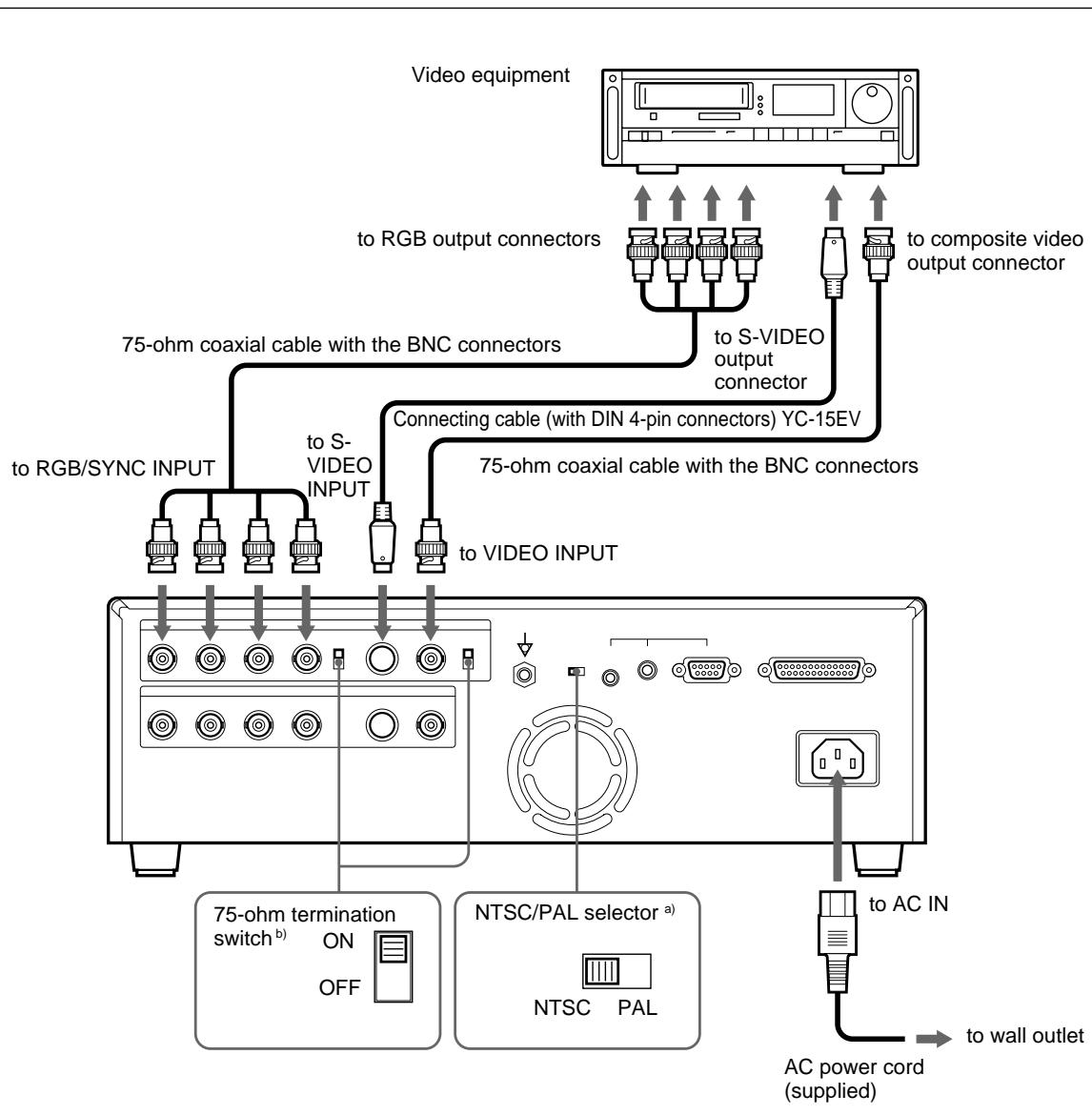
a) This selector is supplied with models other than UP-51MDU. Set the NTSC/PAL selector to your TV system. To switch the TV system, turn the power off once, then change the setting. If you change the setting with the power on, this mode will not be switched.
b) Two kinds of 75-ohm termination switches are provided; one is for the RGB input and the other is for the composite video signal. Normally set this switch to ON. Set it to OFF if the level of the input signal drops because the signal is divided to additional video equipment other than the printer.
Making Connections for Viewing Images to be Printed
Connect a video monitor to view stored images and to check those to be printed.
Connect the required video monitor which will be used in actual printing, using the following diagram as a guide.
Before connecting the video equipment, see "Important safeguards/ notices for use in the medical environments" for UP-51MD/51MDU/51MDP on page 2.
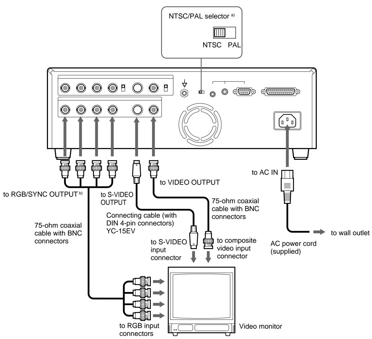
a) This selector is supplied with models other than UP-51MDU. Set the NTSC/PAL selector to your TV system. To switch the TV system, turn the power off once, then change the setting. If you change the setting with the power on, this mode will not be switched.
b) See "When connecting the video monitor to the RGB SYNC OUTPUT connectors" on the next page.
When connecting the video monitor to the RGB SYNC OUTPUT connectors
Normally, set SYNC ON G in the OUTPUT SETUP menu to ON.
Set SYNC ON G to OFF in the following case: If the images displayed on the video monitor become greenish, compared with the printout, adjust the video monitor color (set the adjusted value of the video monitor color to the default). (See "Matching the Video Monitor Color to the Printer Color" on page 83.) If the images on the video monitor are still greenish, set SYNC ON G to OFF.
Making Connections to Enable Remote Control
The printer can be controlled remotely by connecting an RM-5500 Remote Control Unit (not supplied), RM-91 Remote Control Unit (not supplied), an FS-30/FS-36 Foot Switch (not supplied) or a personal computer.
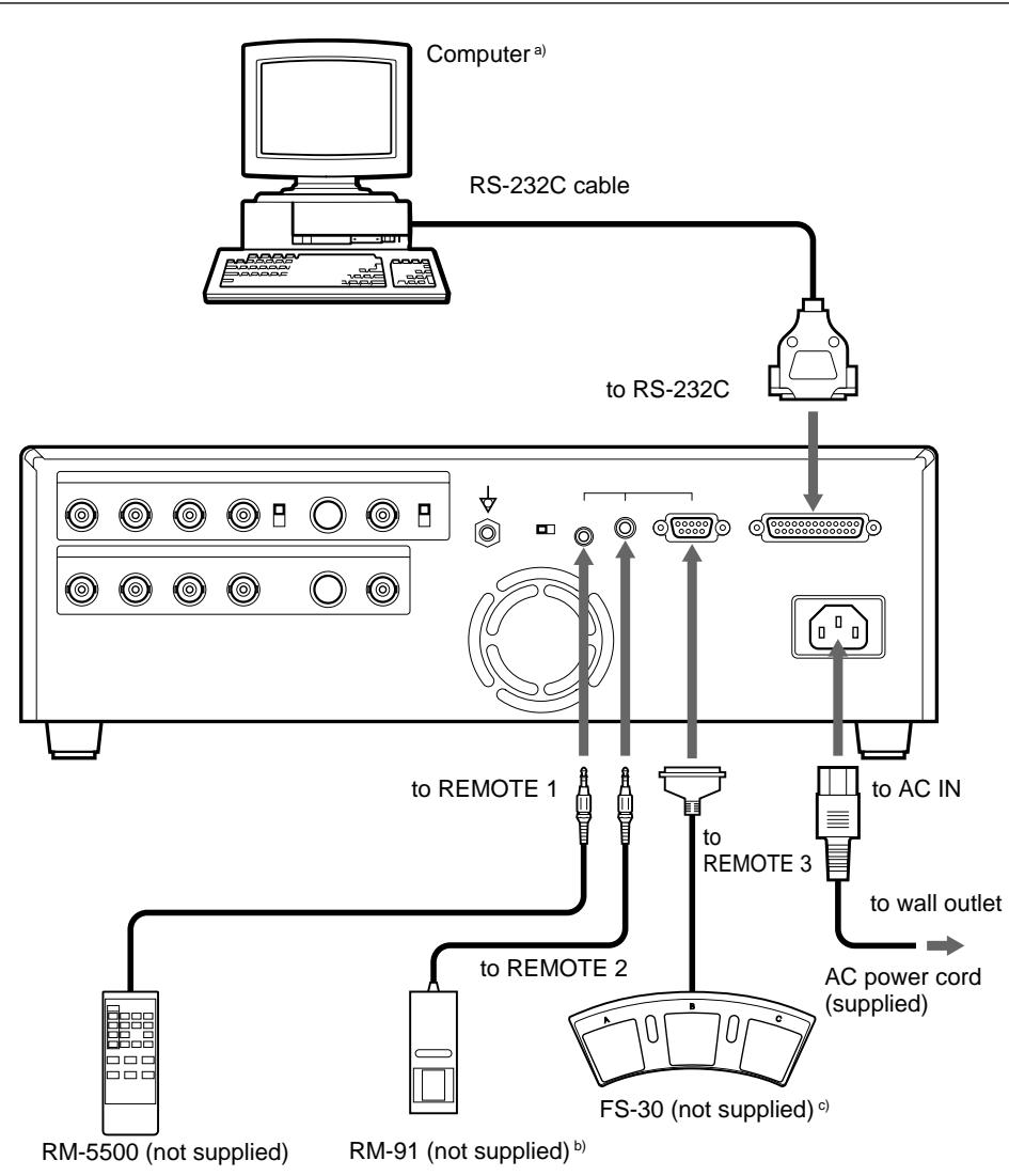
a) When connecting a personal computer, select the appropriate baud rate from the SYSTEM SETUP menu. (See "Setting the Baud Rate for Computer Communication" on page 113.)
b) You can also connect an FS-36 foot switch.
c) You can also control the printer remotely by sending the signal to pin No.5 of the REMOTE 3 connector.
You can set up the printer specifications. Once you have adjusted and stored the settings, the printer operates according to those settings until their values are modified. You can set up the printer according to its intended purpose, connected equipment or your individual preferences.
There are 11 menus. Functions that can be set on those menus are as follows:
| Menu | Functions to be set | Reference page |
| COLOR ADJUST | Adjusting the printout color (color intensity and contrast) and sharpness. | 86 |
| LAYOUT SETUP | • Selecting the memory mode | 34 |
| • Selecting the type of printouts | 37 | |
| • Selecting whether white borders are added to multiple reduced images. | 49 | |
| • Making a printout of mirror images | 53 | |
| • Selecting the lamination pattern | 114 | |
| WINDOW SETUP | • Changing the printout size | 96 |
| • Changing the printout area | 96 | |
| CAPTION | Entering a caption | 57 |
| PRINTER SETUP | • Setting the print quantity | 23 |
| • Selecting whether multiple reduced images are automatically stored at regular intervals. | ||
| • Adjusting the tone of the printout | 92 | |
| • Selecting the print mode | 30 | |
| • Confirming whether the memory image is blurred | 48 | |
| COLOR BALANCE | Adjusting the color balance | 98 |
| SYSTEM SETUP | • Adjusting the brightness of the printer window display. | 110 |
| • Setting the baud rate for computer communication. | 113 | |
| • Selecting whether the operation and error tones sound. | 112 | |
| • Selecting the application mode (printer operation mode) | 31 | |
| • Compensating for the level of the input signal | 81 | |
| • Registering user settings | 116 | |
| USER NAME | Editing the user name | 116 |
| FUNCTION SETUP | • Selecting the image which appears after storing the image into memory, source image or memory image. | 42 |
| • Selecting the timing of the pulse signal input to the REMOTE 2 connector | 106 | |
| • Selecting operation mode for automatic printing capabilities of remote control units connected to REMOTE 2/REMOTE 3 connectors. | 104 | |
| • Setting the function of the CLEAR button | 64 | |
| INPUT SETUP | • Selecting the input signal | 16 |
| • Compensating for the input signals. | 78 | |
| OUTPUT SETUP | • Erasing the screen display. | 68 |
| • Matching the video monitor color to the printout color. | 83 | |
| • Selecting the output signal from the printer | 84 | |
| • Selecting whether the printer synchronizes with the internal sync signal included in channel G of the RGB signals. | 76 | |
| • Selecting whether information on the ink ribbon is displayed | 69 |
This section explains the following settings and adjustments.
- Compensating for the input signals (on this page)
- Matching the video monitor color to the printout color (page 83)
-
Adjusting the printout color
-
Adjusting the color intensity, contrast and sharpness (page 86)
-
Adjusting the tone of the printout (page 92)
-
Changing the printout size/printout area (page 94)
- Adjusting the color balance (page 98)
- Selecting the operating mode for automatic printing capability (page 104)
- Adjusting the printer window display brightness (page 110)
- Selecting whether to enable the operation and error tones (page 112)
- Setting the baud rate for computer communication (page 113)
- Selecting the lamination pattern (page 114)
- Registering the printer settings and adjusted values as a user set (page 116)
Compensating for the Input Signals
A video image recorded under poor conditions may be of poor color quality. If the signal is an NTSC or PAL composite video signal or separate luminance (Y) and chrominance (C) signals, you can correct the color and level of the input signal to a certain extent on the INPUT SETUP menu.
Note
You cannot adjust an image once it has been captured in memory. If you make adjustments, capture that image again, after the adjustment.
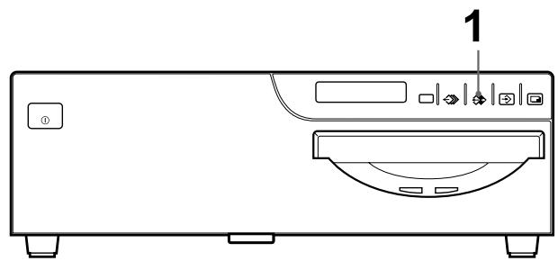
2 3
1 When the memory image is displayed on the screen, press the SOURCE/ MEMORY button.
The image from the video source appears.
2 Press the INPUT SETUP button in the sub panel.
The INPUT SETUP menu appears.
Or press the MENU button and display the INPUT SETUP menu by using the
or button.
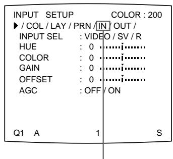
Switch IN to green by pressing the or button.
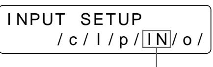
Display IN in capital letters by pressing the or button.
3 Perform the adjustments as follows.
① Select the adjustment item by pressing the or button.
② Perform the adjustment by pressing the or button.
To adjust the color intensity, hue, contrast and brightness
| Adjustment | Menu adjustment item | Button to be pressed and operation result | |
| \L button | \L button | ||
| Hue a) | HUE a) | The hue becomes purplish. | The hue becomes greenish. |
| Color intensity | COLOR b) | The color intensity weakens. c) | The color intensity strengthens. |
| Contrast | GAIN d) | The contrast weakens. | The contrast strengthens. |
| Brightness | OFFSET | Becomes darker. | Becomes brighter. |
a) In PAL mode, no HUE adjustment is provided on the INPUT SETUP menu.
b) Adjust the color such that skin tones appear natural. For the COLOR and HUE adjustment, you can correct the color intensity and hue of an NTSC composite video signal or a separated luminance (Y) and chrominance (C) signal.
c) On a setting of step -14 , OFF appears and the image, displayed on the monitor screen, becomes black and white.
d) To perform adjustment of GAIN, set the AGC (explained below) to OFF.
When the printout or monitor image appears blackish or whitish
Adjust the input signal to the optimum level for printing.
| Menu adjustment item | Selection | When |
| AGC (Automatic Gain Control) | ONa) | The printout or monitor image appears blackish or whitish. |
| OFF | The proper signal is input. (Normal) |
a) Adjust GAIN under the condition where AGC is set to ON.
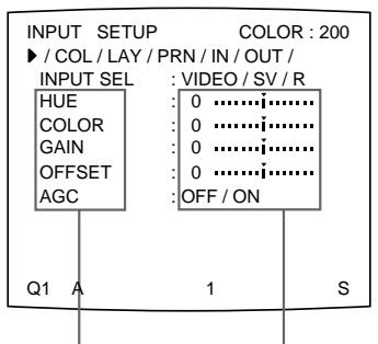
① Position the cursor at the desired item by pressing the or button.
(2) Make adjustment by pressing the or button.
① Press the 口 or 口 button until the desired item appears.
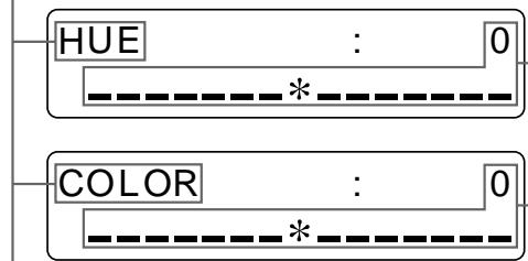
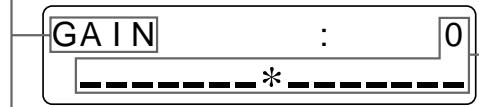
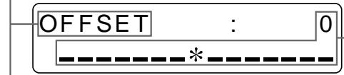
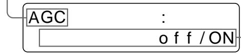
② Make adjustment by pressing the or button
To reset items to defaults (0)
Place the cursor at the adjustment item to be reset, then press the and buttons simultaneously.
4 Press the MENU button.
The regular screen appears.
Compensating for the level of the input signal
The images displayed on the video monitor (in EE mode, see page 84) or printouts still may be whitish due to poor contrast adjustment, even if AGC for the input signal is compensated. In such a case, you can adjust the contrast by adjusting GAIN in the INPUT SETUP menu. However, if you do not want to change the contrast of the video monitor screen, compensate for the level of the input signal in the SYSTEM SETUP menu.
Note
You cannot adjust an image once it has been captured in memory. Capture an image after compensating for the level of the signal input.
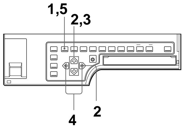
1 Press the MENU button, then select PRN by pressing the or button. The PRINTER SETUP menu appears.
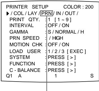
Switch PRN to green by pressing the or button.

Display PRN in capital letters by pressing the or button.
2 Select SYSTEM by using the or button, then press the button. The SYSTEM SETUP menu appears.
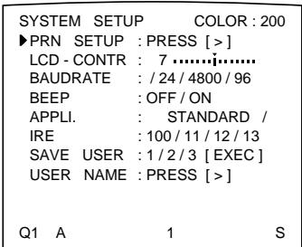
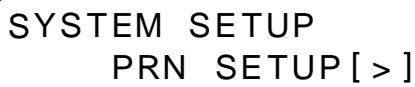
3 Select IRE by pressing the or button.
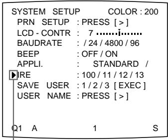
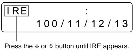
Position the cursor at IRE by pressing the or button.
4 Select the desired IRE value by pressing the or button. The selected IRE is displayed in three digits.
| When | IRE value |
| Resetting to the standard adjustment | 10 → 100 |
| The printout is a little whitish. | 11 → 110 |
| The printout is whitish. | 12 → 120 |
| The printout is very whitish. | 13 → 130 |
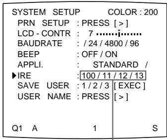
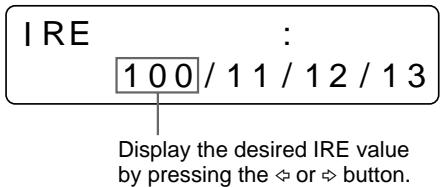
Switch the desired IRE value to green by pressing the or button.
Note
Do not compensate for the input signal too much. Doing so results in the whole of the printout becoming dark.
5 Press the MENU button. The regular screen appears.
Matching the Video Monitor Color to the Printer Color
To match the color of the monitor image to that of the printout, adjust the monitor and printer colors such that the monitor color is the same as that of the printout. The printer outputs either of two kinds of video signals according to the printer settings.
- EE (E to E): Signals are output to the monitor after being processed by the printer's circuitry.
- THRU (THROUGH): Signals are output to the monitor as is.
Adjustment on the video monitor
The monitor color may not be adjusted correctly even if the printer color is correctly adjusted. Check the color of the video monitor before adjusting the printout color. In such a case, use the THRU signal by setting SOURCE to THRU in the OUTPUT SETUP menu or turning off the power of the printer to send out the through signal from the video equipment to the video monitor
After adjusting the color of the video monitor using video monitor controls, adjust the color of the printer's output signal.
Adjustment on the printer
Note
This adjustment is performed to adjust the color of the printer output signal when the monitor color is unsatisfactory. This adjustment does not affect the printout itself. To adjust the color of the printout, see "Adjusting the Printout Color" on page 86.
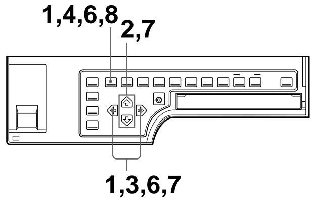
1 Press the MENU button, then select OUT by pressing the or button. The OUTPUT SETUP menu appears.
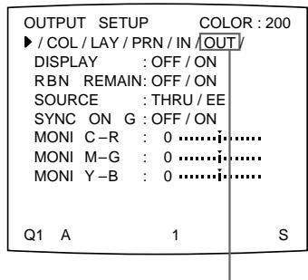
Switch OUT to green by pressing the or button.
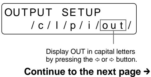
Installation and Adjustment
2 Select SOURCE by pressing the or button.
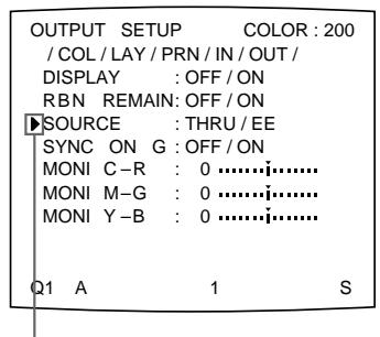
Position the cursor at SOURCE by pressing the or button.
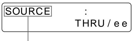
Press the or button until SOURCE appears.
3 Select EE by pressing the or button.
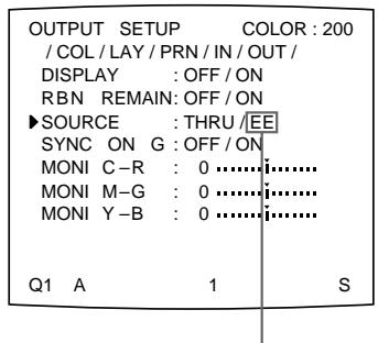
Switch EE to green by pressing the or button.
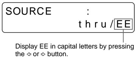
4 Press the MENU button. The regular screen appears.
5 Capture a new image in memory and make a printout. Adjust the settings on the printer side by comparing the printout with the image on the monitor, as follows.
6 Press the MENU button, then select OUT by pressing the or button. The OUTPUT SETUP menu appears.
7 Adjust the monitor while comparing the printout with the image on the monitor.
① Select the adjustment item by pressing the or button.
② Perform adjustment by pressing the or button.
| Menu adjustment item | When you want to | Button to be pressed | Adjustment direction on the menu |
| MONI C-R | Make the screen more reddish. | ✕ button | Toward R (red) |
| Make the screen become cyan (blue). | ✕ button | Toward C (cyan) | |
| MONI M-G | Make the screen more greenish. | ✕ button | Toward G (green) |
| Make the screen become magenta (pink) | ✕ button | Toward M (magenta) | |
| MONI Y-B | Make the screen more bluish. | ✕ button | Toward B (blue) |
| Make the screen more yellowish. | ✕ button | Toward Y (yellow) |
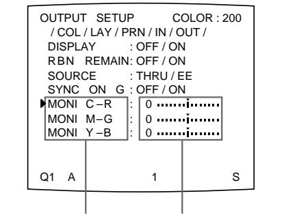
① Position the cursor at the desired adjustment item by pressing the 念 or button.
② Make adjustment by pressing the or button.
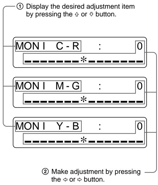
To reset items to defaults (0)
Place the cursor at the adjustment item to be reset, then press the and buttons simultaneously.
8 Press the MENU button.
The regular screen appears.
Adjusting the Printout Color
You can adjust the printout quality by adjusting the color intensity, printout sharpness and tone (GAMMA) of the printout.
Adjusting the color intensity, contrast and sharpness
You can adjust the color intensity (RED/GREEN/BLUE), contrast (DARK/LIGHT) and printout sharpness (SHARPNESS/INTERPOL.). You can store up to three settings.
These settings are managed according to the LOAD COLOR number. The color intensity, picture contrast and sharpness of a printout are determined by recalling one of the three settings according to their LOAD COLOR numbers. This is useful when you are using more than one item of video equipment, each having different characteristics, when you want to print images having different color qualities and picture contrast, and when multiple users access a single printer.
Also, you can make a printout using temporarily set values, without erasing the stored adjustment values.
Perform the adjustments while viewing the images stored in memory.
All values of the color intensity and contrast are factory-set to 0 and the SHARPNESS is set to 8 for LOAD COLOR numbers 1, 2 and 3.
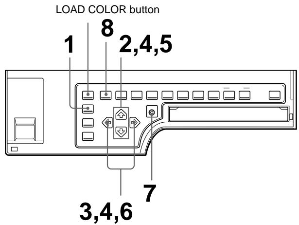
1 Press the R/G/B/D/L button on the sub panel. The COLOR ADJUST menu appears.
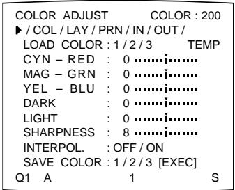
COLOR ADJUST /COL/1/p/i/o/
Or press the MENU button and display the COLOR ADJUST menu by pressing the or button.
2 Select LOAD COLOR by pressing the or button.
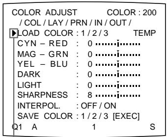
Position the cursor at LOAD COLOR by pressing the 当 or 当 button.
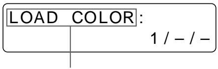
Display LOAD COLOR by pressing the or button.
3 Select the LOAD COLOR number of the values to be adjusted or to be modified by pressing the or button.
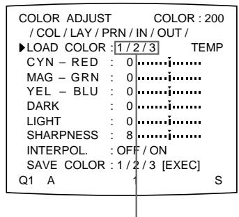
Switch the desired LOAD COLOR number to green by pressing the or button.
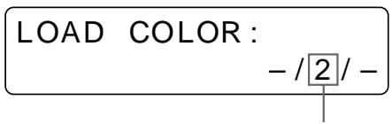
Display the desired LOAD COLOR number by pressing the or button.
When modifying, you can preserve the original settings. (See “To retain the originally set value” on page 91.)
Continue to the next page
4 Adjust the printout color.
① Select the item to be adjusted by pressing the or button.
② Perform the adjustment by pressing the or button.
The RED, GREEN and BLUE color component and contrast settings are divided into 15 steps, from -7 to +7 , indicated by a value and graph. The center of the graph (0) corresponds to the standard color.
SHARPNESS is divided into 15 steps from 1 to 15, indicated by a value and graph. A setting of step 8 corresponds to the standard sharpness.
For INTERPOL. (interpolation), select either ON or OFF depending on the type of image
When adjusting the RED/GREEN/BLUE (color intensity)
| Menu Adjustment item | When you want to | Button to be pressed | Adjustment direction on the menu |
| CYN-RED | Make the image reddish. | \L button | Toward RED |
| Make the image cyan. | \L button | Toward CYN (cyan) | |
| MAG-GRN | Make the image magenta (pink). | \L button | Toward MAG (magenta) |
| Make the image greenish. | \L button | Toward GRN (green) | |
| YEL-BLU | Make the image yellowish. | \L button | Toward YEL (yellow) |
| Make the image bluish. | \L button | Toward BLU (blue) |
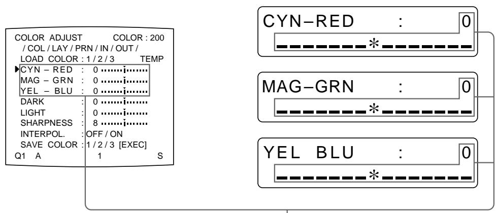
Adjust the color intensity for each adjustment item.
When adjusting DARK/LIGHT (contrast)
| Adjustment item | When you want to |
| DARK | Adjust the dark area of an image. |
| LIGHT | Adjust the light area of an image. |
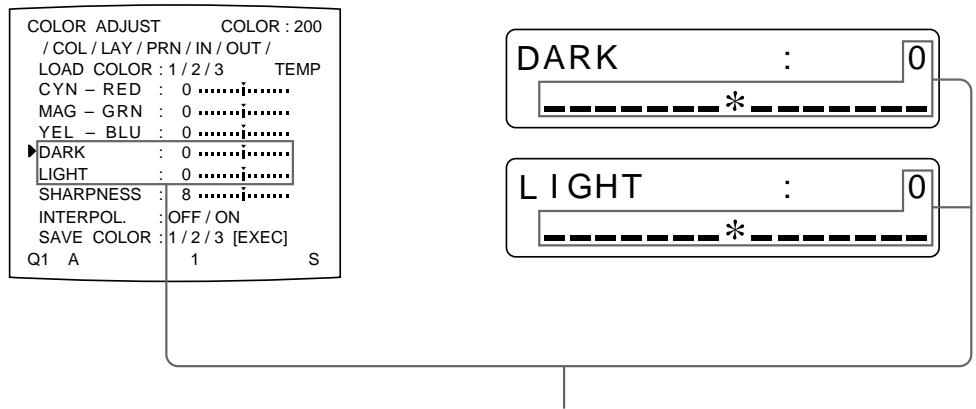
The contrast in the dark area or light area is increased in the + direction by pressing the button.
The contrast in the dark area or light area is weakened in the - direction by pressing the button.
When adjusting the sharpness SHARPNESS
You can set the sharpness to any of 15 steps from 1 to 15. A setting of step 8 corresponds to the standard sharpness (default setting).
| When you want to | Content of settings |
| Make a soft outline. | To the left (toward step 1) |
| Make a normal outline. | Centered (step 8) |
| Make a sharp outline. | To the right (toward step 15) |
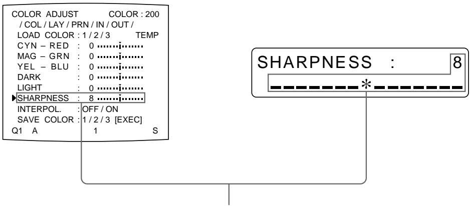
The number and the corresponding sharpness increase every time you press the button.
The number and the corresponding sharpness decrease every time you press the button.
Continue to the next page
INTERPOL. (Interpolation)
| When you want to | Setting |
| Print out image data such as a figure image or a landscape. | ON |
| Print out image data of computer graphics or with small letters | OFF |
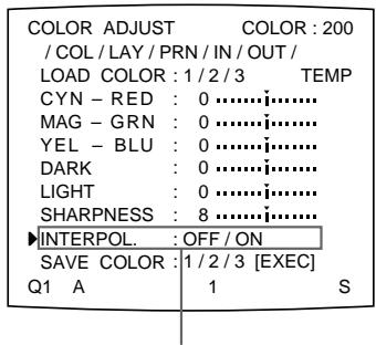
Switch the desired setting to green by pressing the or button.

Display desired setting in capital letters by pressing the or button.
Note
Effectiveness of SHARPNESS may differ between ON and OFF settings of INTERPOL.
To reset items to defaults (0)
Place the cursor at the adjustment item to be reset, then press the and buttons simultaneously.
Once you have changed the value
Once you have changed the value, TEMP (temporary) appears on the menu screen. TEMP indicates that the settings are temporary and have not yet been stored. If you turn off the power of the printer while TEMP is displayed, the adjusted values are not stored.
5 Select SAVE COLOR by pressing the or button.
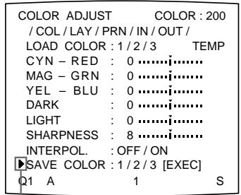
Position the cursor at SAVE COLOR by pressing the 念 or 念 button.

Display SAVE COLOR by pressing the or button.
6 Select the SAVE COLOR number to which new settings are to be stored by pressing the or button.
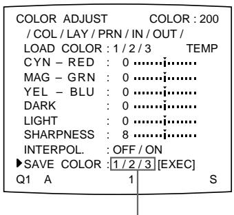
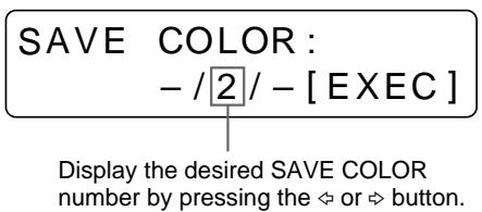
Switch the desired SAVE COLOR number to green by pressing the or button.
To retain the originally set value
Select a SAVE COLOR number which is different from the LOAD COLOR number selected in step 3.
7 Press the EXEC button.
The settings are registered in the SAVE COLOR number selected in step 6. TEMP disappears from the menu.
8 To continue settings for another LOAD COLOR number, repeat steps 3 to 7. To finish the setting, press the MENU button.
The regular screen appears.
To copy the settings made for one LOAD COLOR number to another LOAD COLOR number
1 Select the source LOAD COLOR number for which the settings to be copied are stored in the COLOR ADJUST menu.
2 Select the target SAVE COLOR number to which data is to be copied.
3 Press the EXEC button.
Settings stored to the LOAD COLOR number selected in step 1 are copied to the SAVE COLOR number selected in step 2.
To recall the LOAD COLOR number in which printout color settings (color intensity, contrast and sharpness) are stored
Switch the desired LOAD COLOR number to green in the COLOR ADJUST menu.
Or press the LOAD COLOR button on the sub panel. Each time you press the button, the currently selected LOAD COLOR number is displayed for about three seconds. To select the desired LOAD COLOR number, release the button while the desired number is displayed.
The printout is made according to the setting of the selected LOAD COLOR number as long as you do not modify those settings.
Adjusting the tone of the printout
You can adjust the tone so that the details in the white or black part are clearly printed.
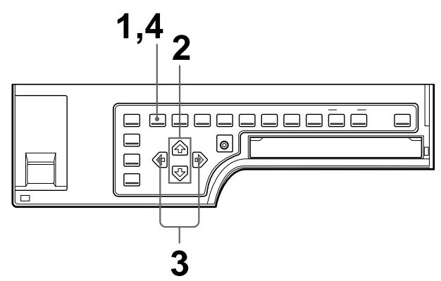
1 Press the MENU button, then select PRN by pressing the or button. The PRINTER SETUP menu appears.

Switch PRN to green by pressing the or button.
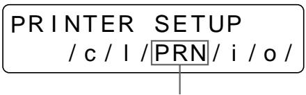
Display PRN in capital letters by pressing the or button.
2 Select GAMMA by pressing the or button.
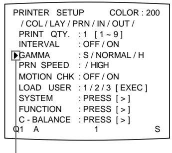
Position the cursor at GAMMA by pressing the or button.
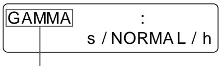
Display GAMMA by pressing the 口 or 口 button.
3 Select the desired tone by pressing the or button. The selected tone is spelled out.
| When you want to | Setting |
| Make a printout of an image where there are a lot of white or light-colored areas. | S → SOFT |
| Make a printout of a normal image. | N → NORMAL |
| Make a printout of an image where there are a lot of black or dark-colored areas. | H → HARD |
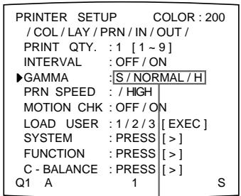
Switch the desired tone to green by pressing the or button.
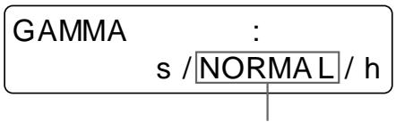
Display the desired tone by pressing the or button.
4 Press the MENU button. The regular screen appears.
Changing the Printout Size/Printout Area
When you print an image that is narrower or wider than the standard screen size, a black frame may be printed or the image may be partially cut. In such a case, you can change the screen size. Or, a black line may be produced on the printout even though it does not appear on the video monitor. Any portion for which there is no video signal is printed in black. This may occur when you make printouts after connecting a different video source or play back using different video software. In such a case, you can adjust the printout area by moving the screen either horizontally or vertically. When a black frame appears around the printout, even after the printout area has been shifted, narrow the printout size because the image has been overscanned beyond the range of the regular screen.
Note
This adjustment affects only the input signal. This adjustment does not affect the image captured in the memory.
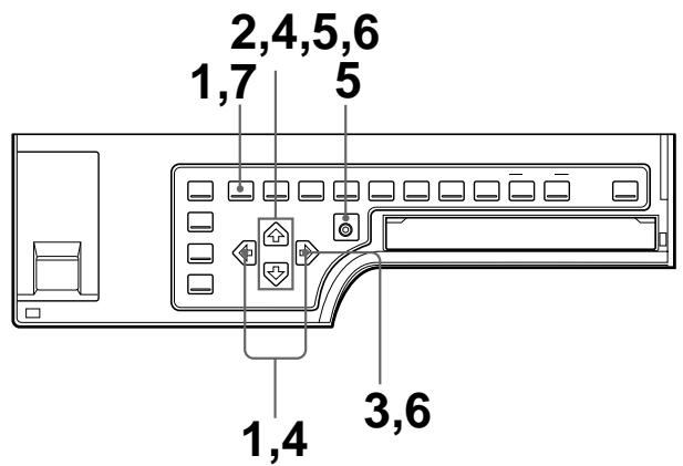
1 Press the MENU button, then select LAY by pressing the or button. The LAYOUT SETUP menu appears.
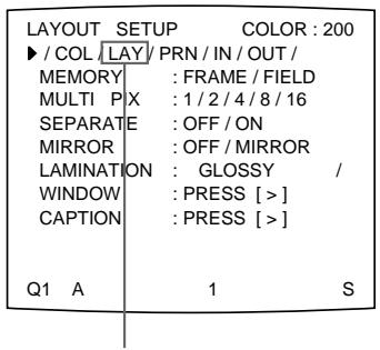
Switch LAY to green by pressing the or button.
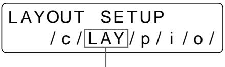
Display LAY in capital letters by pressing the or button.
2 Select WINDOW by pressing the or button.
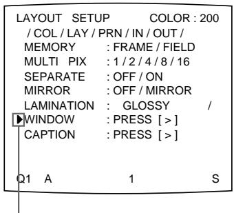
Position the cursor at WINDOW by pressing the or button.
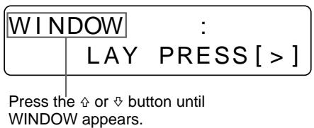
Note
If you go to the next step after you select WINDOW in step 2, the images stored in the memory will be cleared.
3 Press the button.
The WINDOW SETUP menu appears.
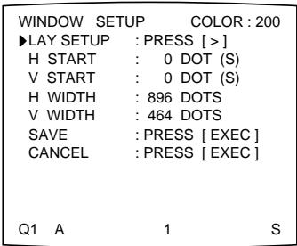

4 Adjust the printer according to the printout obtained.
① Select the item to be adjusted by pressing the or button.
② Perform the adjustment by pressing the or button.
Continue to the next page
When a black frame is printed or the image is partially cut
Adjust the printout size by using the H WIDTH and V WIDTH items from the menu.
| When you want to | Menu adjustment item (defaults) | Button to be used | Adjustment result |
| Change the screen size horizontally and adjust the position of the right edge. The left edge remains fixed. | H-WIDTH (NTSC: 896, PAL: 896) | 按钮 | Widened at the right edge (toward the right direction of the screen). |
| 按钮 | Narrowed with the left edge remaining fixed. | ||
| Change the screen size vertically and adjust the position of the bottom edge. The top edge remains fixed. | V-WIDTH (NTSC: 464, PAL: 560) | 按钮 | Enlarged downwards. |
| 按钮 | Vertical size reduced with the top edge remaining fixed. |
Adjusting the printout size horizontally.
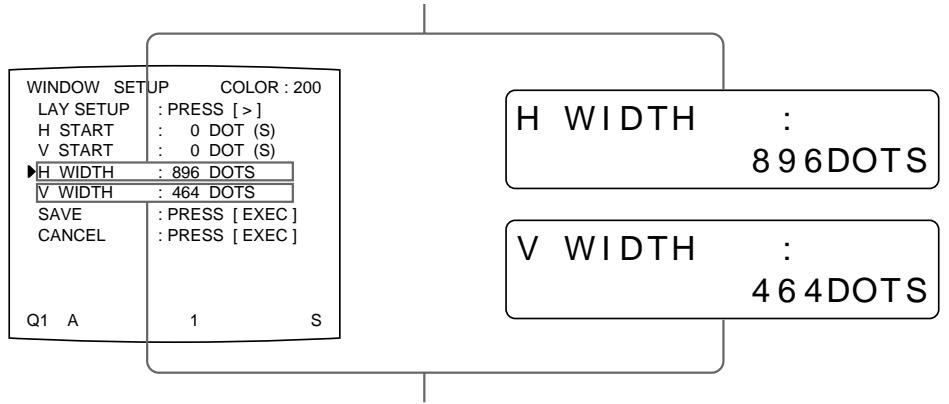
Adjusting the printout size vertically.
When a black line appears on the printout
Adjust the printout area according to the position of the line on the printout, by using the H START and V START items on the menu.
| Position where the black line appears | Menu adjustment item (defaults) | Button to be used | Adjustment result |
| On the right | H START (NTSC/PAL: 0) | \L button | The image position shifts to the right with the size remaining as is. |
| On the left | \L button | The image position shifts to the left with the size remaining as is. | |
| At the top | V START (NTSC/PAL: 0) | \L button | The image position shifts up with the size remaining as is. |
| At the bottom | \L button | The image position shifts down with the size remaining as is. |
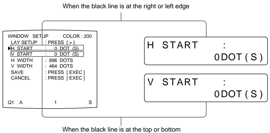
Note
When a black line still appears, even after adjusting H START or V START, change the printout size.
5 Select SAVE by pressing the or button, then press the EXEC button. The adjusted values are stored. The LAYOUT SETUP menu appears.
6 Press the MENU button.
The regular screen appears.
To clear the adjusted value
Select CANCEL in step 5, then press the EXEC button on the sub panel. The values adjusted in step 4 are cleared and the values are reset to the original ones.
To reset the adjusted value to defaults
Press the and buttons simultaneously. The adjusted values are reset to the defaults.
To check the adjustment result
Capture a new image and print it to check that no black frame appears on the printout, that the image is not partially cut, and that no black line appears.
Adjusting the Color Balance
You should use the ink ribbon and paper that are contained in the same package as a pair. The color balance may differ depending on each pair.
It is recommended that you adjust the color balance each time you load a new ink ribbon and paper.
Before adjusting the color balance
Reset all items in the COLOR ADJUST menu to defaults. (See “Adjusting the Printout Color” on page 86.)
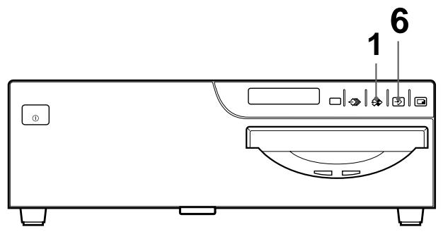
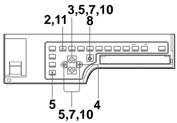
1 Display the source image on the video monitor by using the SOURCE/ MEMORY button.
2 Press the MENU button, then select PRN by pressing the or button. The PRINTER SETUP menu appears on the source image.
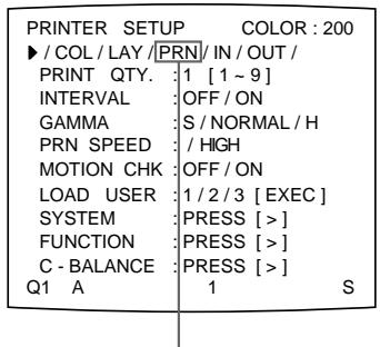
Switch PRN to green by pressing the or button.
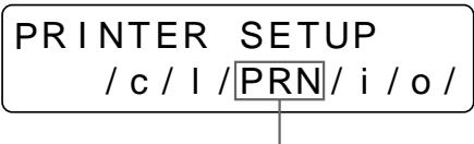
Display PRN in capital letters by pressing the or button.
3 Select C-BALANCE by pressing the or button.
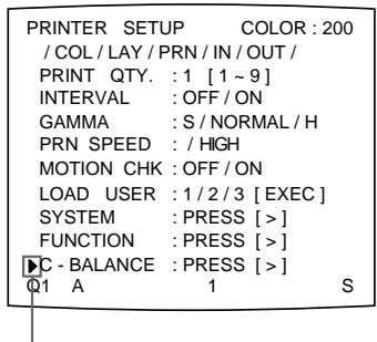
Position the cursor at C-BALANCE by pressing the 口 or 口 button.
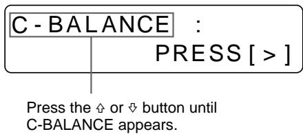
4 Press the button.
The COLOR BALANCE menu appears.
The highlighted area will be printed for adjusting the color balance.
You can move this area at any place on the video monitor.
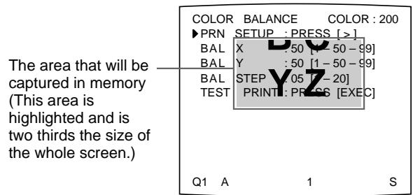
When you adjust the color balance for the first time after you purchase the printer, the values of BAL X, BAL Y and BAL STEP are set to 50, 50 and 05 at the factory.
The BAL STEP is the adjustable range for each color balance.
When you have adjusted color balance already, the values adjusted previously are displayed on the COLOR BALANCE menu.
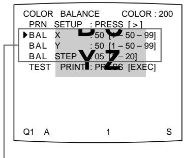
The currently adjusted values of BAL X, BAL Y and BAL STEP
On this COLOR BALANCE menu, the default values (factory settings) are displayed.
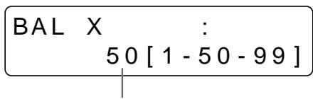
The currently adjusted value of BAL X In this printer window display, the default value of BAL X is displayed.
To reset the values to defaults (50/50/05)
Select each item by pressing the or button, then press the and buttons at the same time. The currently selected item is reset to the default.
5 Decide the position of the source image to be used for adjusting the color balance.
To decide the position of the source image, move the highlighted area by pressing the , , or button while holding down the DISPLAY button on the sub panel.
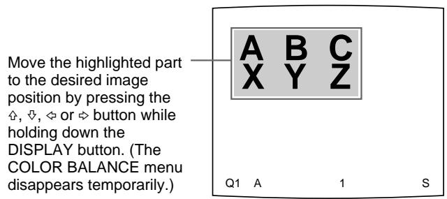
6 Press the CAPTURE button.
The image captured in memory appears.
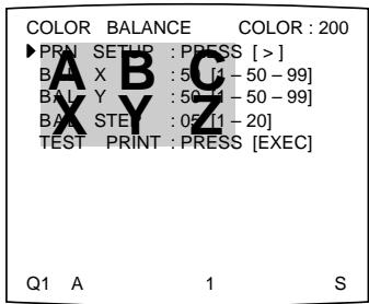
7 Select TEST PRINT by pressing the or button.
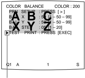
Position the cursor at TEST PRINT by pressing the or button.
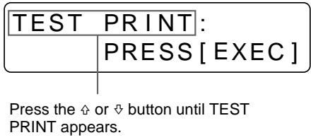
8 Press the EXEC button.
Nine identical images are printed on a sheet of paper as a test print. Each image has a different color balance.
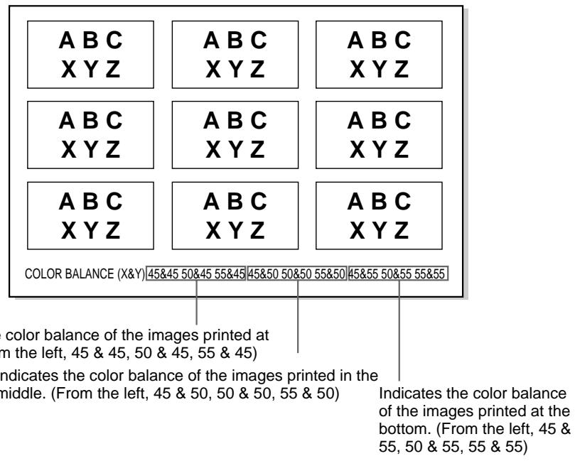
Example of the actual color change in the test print
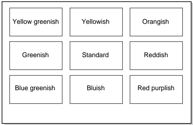
9 Select the image which has the best color balance among the nine images.
If you want to change the color balance after you see the printout, adjust the color balance again, referring to "To readjust the color balance" on page 102.
Continue to the next page
10 Display the values of BAL X and BAL Y corresponding to the ones of the image selected in step 9 by using the or button.
Example: When the color balance (55 & 45) of the image printed on the bottom left is the best:
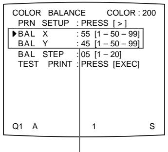
Display 55 for BAL X and 45 for BAL Y by pressing the or button.
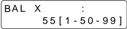
Display BAL X by pressing the or button, then 55 by pressing the or button.
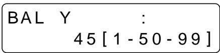
Display BAL Y by pressing the or button, then 45 by pressing the or button.
The color balance has been adjusted to the values selected in step 9.
11 Press the MENU button.
The regular screen appears.
To readjust the color balance
When the desired color balance cannot be obtained in step 9, readjust the color balance.
You can also perform fine adjustment following the same operation procedures.
1 Display the values of BAL X and BAL Y of the image which is the most appropriate among nine images.
In this case, you can perform fine adjustment or rough adjustment by changing the value of BAL STEP.
To perform fine adjustment
To perform color balance adjustment within the current color balance range, reduce the value of BAL STEP.
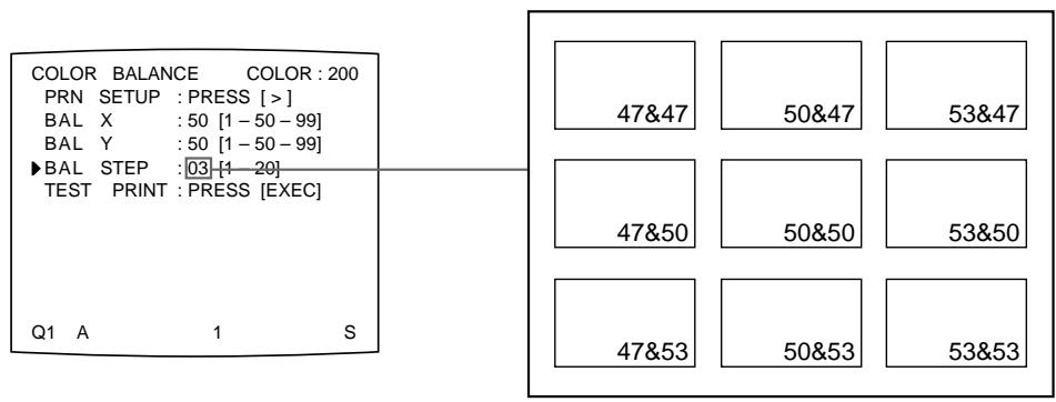
If you change BAL STEP from 05 to 03, the color balances of the test print are changed as illustrated.
Note
The above illustration indicates the color balance when the balance step is changed from 05 to 03. However, on the actual printout, values of the color balance are not printed on each image. They are printed on the bottom of the printout.
To perform rough adjustment
To perform color balance adjustment beyond the current color balance range, increase the value of the BAL STEP.
If you change BAL STEP from 05 to 10, the color balances of the test print are changed as illustrated.
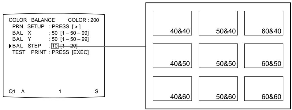
2 Make a test print by repeating steps 5, 6, 7 and 8 in "Adjusting the Color Balance" on page 98.
3 Select the image with the best color balance among the 9 images, if you can decide. Then display the values of BAL X and BAL Y by using the , , or button.
Repeat steps 1 and 2 until you have obtained the best color balance.
4 Go back to step 10 in "Adjusting the Color Balance" on page 102.
Selecting the Operation Mode for Automatic Printing Capabilities
You can control the printer using either of the following remote control units connected to the REMOTE 2 or REMOTE 3 connector on the rear panel of the printer.
- RM-91 Remote control unit (not supplied): Connected to the REMOTE 2 connector
- FS-30 Foot switch (not supplied): Connected to the REMOTE 3 connector. In addition, you can also remote control the printer by using a remote control unit which sends the remote control signal to the Pin No.5 of the REMOTE 3 connector.
Using the menu, you can assign the desired functions to the remote control unit connected to the REMOTE 2 or REMOTE 3 connector.
In addition, the printer can be remotely controlled by a pulse signal input to REMOTE 2 or REMOTE 3. (See pages 126 and 127).
Also, you can control the printer using a personal computer.
For detailed information on controlling with the computer, contact with your Sony dealer.
Note
The FS-36 foot switch is connected to REMOTE 2 to control the printer. However, the function of this foot switch cannot be assigned using the menu.
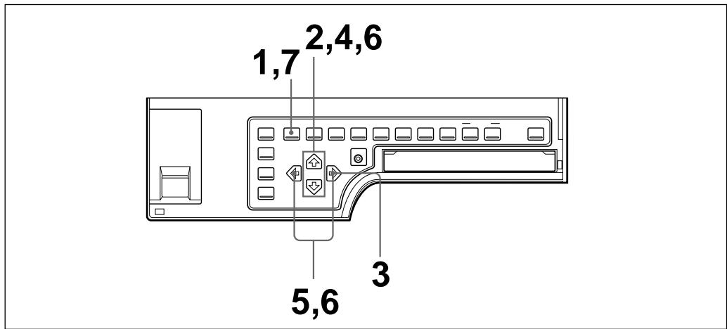
1 Press the MENU button, then select PRN by pressing the or button. The PRINTER SETUP menu appears on the source image.
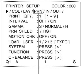
Switch PRN to green by pressing the or button.
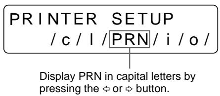
2 Select FUNCTION by pressing the or button.
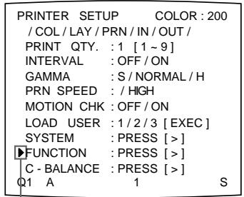
Position the cursor at FUNCTION by pressing the 出 or 出 button.
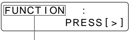
Press the or button until FUNCTION appears.
3 Press the button. The FUNCTION SETUP menu appears.
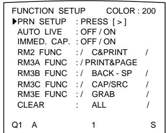
FUNCTION SETUP PRN SETUP[>]
To assign the functions of a remote control unit connected to REMOTE 2, go to step 4.
To assign the functions of a remote control unit connected to REMOTE 3 (3A/3B/3C/3E), go to step 6.
4 Select IMMED. CAP by pressing the or button.
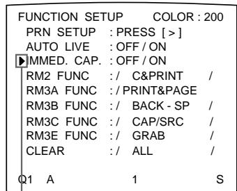
Position the cursor at IMMED. CAP by pressing the or button.
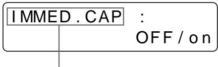
Press the 当 or 当 button until IMMED. CAP appears.
Continue to the next page
5 Select the timing to capture the image by pressing the or button.
| when you want to | Selection |
| Capture the image just after the trigger pulse is input to REMOTE 2 connector. a) | ON |
| Capture the image a certain interval after the trigger pulse is input to the REMOTE 2 connector. b) | OFF |
a) When IMMED. CAP is set to ON, display the source image on the video monitor when sending the trigger pulse to the printer. The printer operation is set only to capture the image when receiving the trigger pulse.
b) The timing is decided at the factory.
For detailed information on the timing for the REMOTE 2 connector, see page 126.
Notes
- Select ON when you want to capture the image at the precise timing controlled from the computer.
- To assign the function to the remote control unit connected to the REMOTE 2 connector on the FUNCTION SETUP menu, set the IMMED.CAP item on the FUNCTION SETUP menu to OFF.
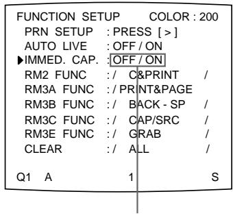
Switch the desired timing selection to green by pressing the or button.
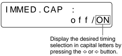
6 Select the remote control unit and assign the function to the selected remote control unit.
① Select the remote control unit to which you want to assign a function by pressing the or button.
| Remote control unit to which the function is assigned | Remote control unit name written on the menu | |
| RM-91 connected to REMOTE 2 | RM2 FUNC | |
| FS-30 connected to REMOTE 3 | Button A of FS-30 | RM3A FUNC |
| Button B of FS-30 | RM3B FUNC | |
| Button C of FS-30 | RM3C FUNC | |
| Remote control unit that sends the trigger pulse to Pin No.5 of REMOTE 3 | RM3E FUNC | |
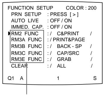
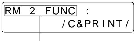
Display the desired remote control unit by pressing the or button.
Position the cursor at the desired remote control unit by pressing the or button.
The figure shows the case where you want to assign a function to the remote control unit connected to REMOTE 2. You can select any remote control unit in the same way.
② Assign a function to the remote control unit selected in 1 by pressing the or button.
| Function to be selected | Operation |
| GRAB | Captures an image when you press the switch of the remote control unit. When the type of multiple reduced images has been selected, the cursor (green pointer) does not move on the video monitor. Also, the memory page is not changed. |
| CAPTURE | Has the same function as the CAPTURE button on the printer. |
| Has the same function as the PRINT button on the printer. | |
| C & PRINTa) (CAPTURE & PRINT) | Captures an image to a memory page where there is not queued image to be printed. If you press the switch while printing is being performed, the selected image is queued, with the queued image being printed once printing has been completed. |
| CYCLIC-Cb) (CYCLIC CAPTURE) | Captures images to memory pages where there are not queued images, cyclically whenever you press the switch. The printer continues to capture images, replacing the one previously captured with a new one. |
| CAP-STOPb) (CAPTURE STOP) | Captures images in a memory page when you press the switch of the remote control unit. Once images have been captured in all the memory pages, the printer stops capturing images and the message HIT ANY KEY appears. |
| BACK-SP (CAPTURE BACK) | The pointer (green) returns to its former position whenever you press the switch when the type of multiple reduced images has been selected. |
| POINTER+ | The cursor (green pointer) moves to the next position whenever you press the switch when the type of multiple reduced images has been selected. |
| STOP | Stops printing after the current printing operation is finished whenever you press the switch of the remote control unit. |
Continue to the next page
| Function to be selected | Operation |
| CAP/SRC (CAPTURE/SOURCE) | When the memory image is displayed, the source image appears whenever you press the switch. When the source image is displayed, the image is captured in memory whenever you press the switch of the remote control unit. However, the memory page is not changed. The previously captured image is replaced with the new one. |
| C/SRC PAGE b) (CAPTURE/SOURCE PAGE) | When the memory image is displayed, the source image appears whenever you press the switch of the remote control unit. When the source image is displayed, the image is captured in memory whenever you press the switch. The memory page is also changed. The captured image is not printed. |
| PRINT & PAGE | Starts to print when you press the switch if the image has been captured in the memory, and at the same time moving to the next memory page. If the image has not been captured in the memory page, the printer does not work correctly when you press the switch of the remote control unit. |
| SRC & CAP (SOURCE & CAPTURE) | When you press and hold down the switch of the remote control unit, the source image appears. When you release the switch, the image showing at the instant you release the switch is captured. The memory page is not changed. |
| SRC & C PAGE b) (SOURCE & CAPTURE PAGE) | When you press and hold down the switch of the remote control unit, the source image appears. When you release the switch, the image showing at the instant you release the switch is captured. Then, the memory page is changed to the next memory page. The captured image is not printed. |
a) When you use the remote control unit under this function, confirm that the source image is displayed on the video monitor. If not, press the SOURCE/MEMORY button so that the source image will be displayed. When multiple reduced images are captured, after the last image is captured, the printer prints the captured image (or queues printing), then the printer goes to the next memory page.
b) When multiple reduced images are captured, after the last image is captured, the printer goes to the next memory page.
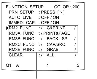
Switch the desired function to green by pressing the or button.
When / is displayed at the right or left end, another function can be selected by pressing the or button.
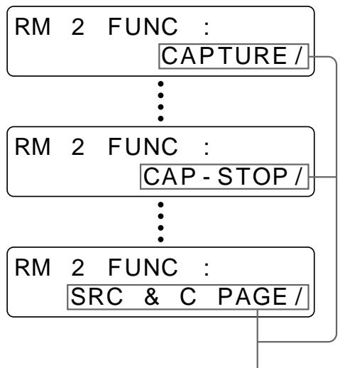
Display the desired function by pressing the or button.
When / is displayed at the right or left end, another function can be selected by pressing the or button.
The function that can be assigned depends on the remote control unit selected in step ①.
The regular screen appears.
Adjusting the Brightness of the Printer Window Display
When it is hard to read the contents of the printer window display, adjust the brightness using the menu.
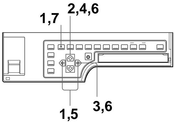
1 Press the MENU button, then select PRN by pressing the or button. The PRINTER SETUP menu appears on the source image.
| PRINTER SETUP COLOR:200 | |
| / COL/LAY/PRN/IN/OUT/ | |
| PRINT QTY. | 1 [1~9] |
| INTERVAL | OFF/ON |
| GAMMA | S/NORMAL/H |
| PRN SPEED | / HIGH |
| MOTION CHK | OFF/ON |
| LOAD USER | 1/2/3 [EXEC] |
| SYSTEM | PRESS [>] |
| FUNCTION | PRESS [>] |
| C-BALANCE | PRESS [>] |
| Q1 A | 1 S |
Switch PRN to green by pressing the or button.
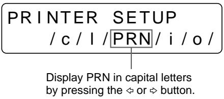
2 Select SYSTEM by pressing the or button.
| PRINTER SETUP COLOR:200 | |
| / COL/LAY/PRN/IN/OUT/ | |
| PRINT QTY.:1 [1~9] | |
| INTERVAL :OFF/ON | |
| GAMMA :S/NORMAL/H | |
| PRN SPEED :/HIGH | |
| MOTION CHK:OFF/ON | |
| LOAD USER:1/2/3[EXEC] | |
| SYSTEM:PRESS[{>} | |
| FUNCTION:PRESS[{>} | |
| C-BALANCE:PRESS[{>} | |
| Q1 A 1 S |
Position the cursor at SYSTEM by pressing the or button.
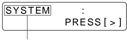
Press the or button until SYSTEM appears.
3 Press the button.
The SYSTEM SETUP menu appears.
| SYSTEM SETUP COLOR : 200 | |
| ◆PRN SETUP : PRESS [>] | |
| LCD-CONTR : 7……… | |
| BAUDRATE : /24/4800/96 | |
| BEEP : OFF/ON | |
| APPLI. : STANDARD / | |
| IRE : 100/11/12/13 | |
| SAVE USER : 1/2/3 [EXEC] | |
| USER NAME : PRESS [>] | |
| Q1 A 1 S |
SYSTEM SETUP PRNSETUP[>]
4 Select LCD-CNTR by pressing the or button.
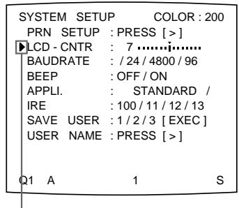
Position the cursor at LCD-CNTR by pressing the 念 or button.
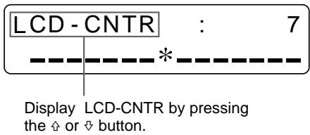
5 Adjust the brightness of the printer window display by pressing the or button.
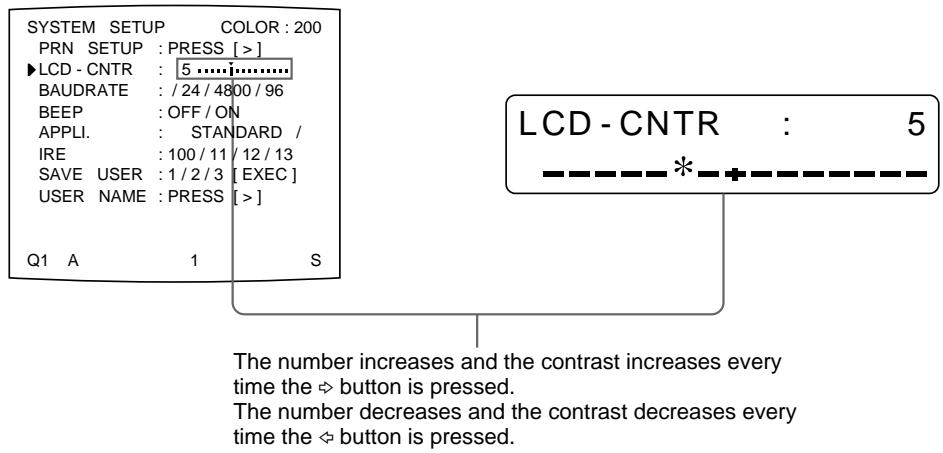
Note
If you select the left end scale, OFF is displayed. In this case, no messages appear in the printer window display when the video monitor returns to the regular screen.
6 Select PRN SETUP by pressing the or button, then press the button. The adjusted values are stored. The PRINTER SETUP menu appears.
7 Press the MENU button.
The regular screen appears.
Selecting Whether the Operation and Error Tones Sound
Whenever you press a button on the front panel or sub panel, the operation tone sounds (one time). When an error occurs, the alarm tone sounds (three times). You can turn these tones on and off using the menu.
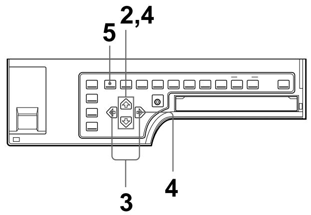
1 Display the SYSTEM SETUP menu.
To display the SYSTEM SETUP menu, see steps 1 to 3 in "Adjusting the Brightness of the Printer Window Display" on page 110.
2 Select BEEP by pressing the or button.
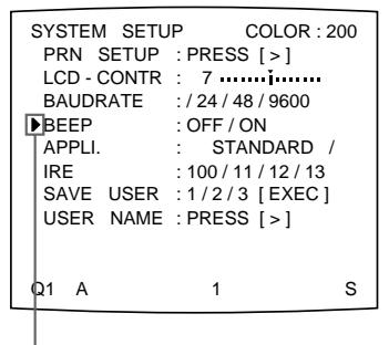
Position the cursor at BEEP by pressing the 出 or 出 button.
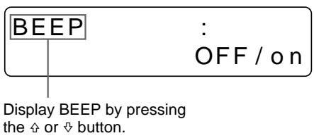
3 Select whether the operation and error tones sound by pressing the or button.
| When you want to | Selection |
| Sound the tones. | ON |
| Disable the tones. | OFF |
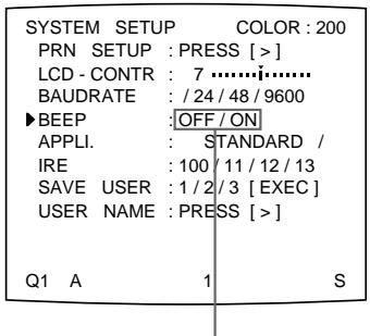
Switch the desired operation to green by pressing the or button.
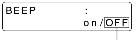
Display the desired operation in capital letters by pressing the or button.
4 Select PRN SETUP by pressing the or button, then press the button. The adjusted values are stored. The PRINTER SETUP menu appears.
Press the MENU button. The regular screen appears.
Setting the Baud Rate for Computer Communication
When controlling the printer with a computer connected to the printer's RS-232C connector, select the appropriate baud rate. For details, contact your nearest Sony dealer.
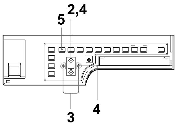
1 Display the SYSTEM SETUP menu. To display the SYSTEM SETUP menu, see steps 1 to 3 in "Adjusting the Brightness of the Printer Window Display" on page 110.
2 Select BAUD RATE by pressing the or button.
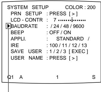
Position the cursor at BAUD RATE by pressing the or button.
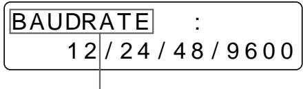
Display BAUD RATE by pressing the 口 or 口 button.
3 Select the desired baud rate by pressing the or button.
| Baud rate (bps) | Baud rate displayed on the menu. (The display changes from first two digit indication to four digit indication.) |
| 1200 | 12 → 1200 |
| 2400 | 24 → 2400 |
| 4800 | 48 → 4800 |
| 9600 | 96 → 9600 |
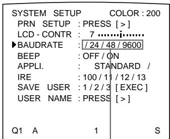
Switch the desired baud rate to green by pressing the or button. The selected baud rate is displayed in four digits.
BAUDRATE :12/24/48/9600
Display the desired baud rate in four digits by pressing the or button.
4 Select PRN SETUP by pressing the or button, then press the button. The adjusted values are stored. The PRINTER SETUP menu appears.
5 Press the MENU button. The regular screen appears.
Selecting the Lamination Pattern
Using the UPC-540 Self-Laminating Color Printing Pack ensures that the printout is well preserved.
You can select the lamination pattern according to the finish you want to have on the printout.
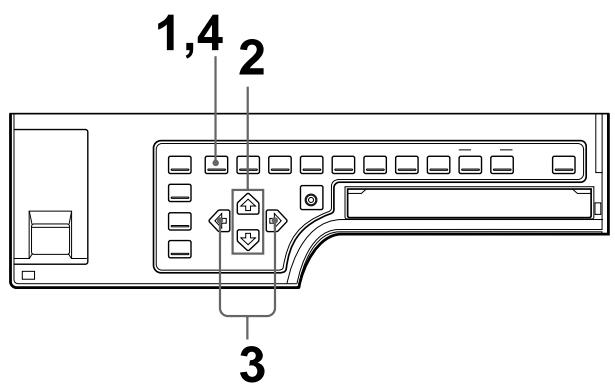
1 Press the MENU button, then select LAY by pressing the or button. The LAYOUT SETUP menu appears on the source image.
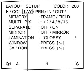
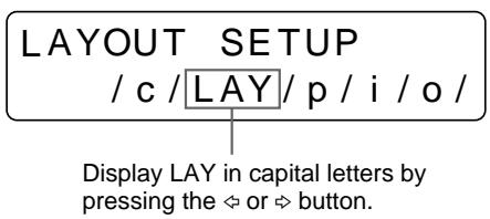
Switch LAY to green by pressing the or button.
2 Select LAMINATION by pressing the or button.
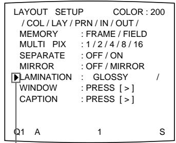
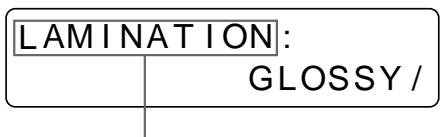
Press the 念 or button until LAMINATION appears.
Position the cursor at LAMINATION by pressing the 出 or 出 button.
3 Select the amination pattern according to the desired finish of printouts by pressing the or button.
| When you want to | Lamination pattern |
| Make a glossy printout. | GLOSSYY |
| Make a printout with a textured finish. | TEXTURE |
| Make a matte printout. | MATTE |
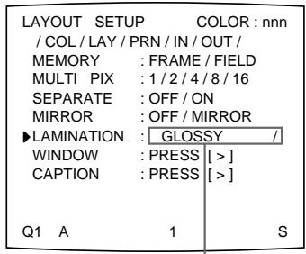
Switch the lamination pattern to green by pressing the or button. When / is displayed at the right or left end, another lamination pattern can be selected by pressing the or button.
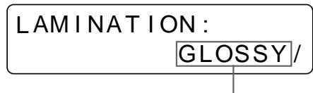
Display the desired lamination pattern by pressing the or button. When / is displayed at the right or left end, another lamination pattern can be selected by pressing the or button.
4 Press the MENU button.
The regular screen appears.
Registering a User Set
You can store up to three settings of all the printer specifications, set or adjusted by using the buttons or with the menu, and store those settings as a user set. The printer retains these setting - even if you turn off the power.
Thus, different operators can make printouts with different settings by recalling the appropriate user set.
If the data of the recalled user set is modified, the printer operates according to the modified data. In such a case, the modified data remains effective until another user set is recalled with the LOAD USER button, even if you turn off the power.
After you finish all of required settings, proceed as follows to register them as a user set.
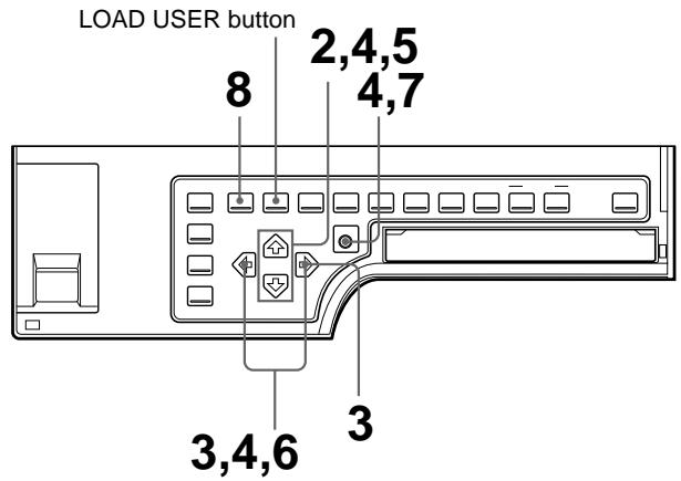
1 Display the SYSTEM SETUP menu.
To display the SYSTEM SETUP menu, see steps 1 to 3 in "Adjusting the Brightness of the Printer Window Display" on page 110.
If you want to name a user set, go to step 2.
If you do not want to name a user set, go to step 5.
2 Select USER NAME by pressing the 四 or 四 button.
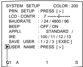
Position the cursor at USER NAME by pressing the 口 or 口 button.
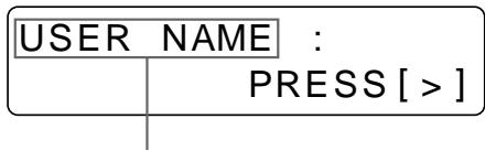
DisplayUSERNAME by pressing the or button.
3 Press the button.
The USER NAME menu appears.
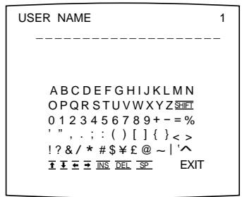
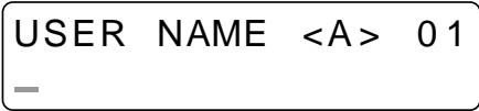
For detailed information on how to enter characters, see “Entering a Caption” on page 57.
You can use up to 16 characters.
4 Select EXIT by pressing the , , or button on the USER NAME menu, then press the EXEC button.
The user name is stored, and the SYSTEM SETUP menu appears again.
5 Select SAVE USER by pressing the or button.
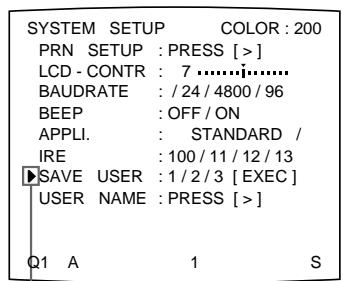
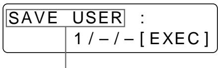
Display SAVE USER by pressing the 出 or 出 button.
Position the cursor at SAVE USER by pressing the 口 or 口 button.
6 Select the desired user set number by pressing the or button.
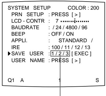
Switch the desired user set number to green by pressing the or button.

Display the desired user set number by pressing the or button.
7 Press the EXEC button.
All data currently set and adjusted are registered in the user set number selected in step 6.
When you name a user set in step 3, the user name is also registered at the same time.
Press the MENU button. The regular screen appears
The printer operates according to this registered data unless you recall another user set. Also, if you modify the settings, the modified data remains effective until another user set is recalled with the LOAD USER button, even if you turn off the power.
To make another user set
Perform all required settings and adjustments using the menus, then register them with another user set number.
To recall the user set and print
Select the desired user set by pressing the LOAD USER button. Each time you press the LOAD USER button, user sets are recalled in the order of 1, 2, 3, 1.... Then, press the EXEC button to execute the selected user set.
The printer operates according to the recalled user set. If you modify the set value, the printer operates according to the modified data until you recall another user set.
Note
If the user set is changed, all images stored in memory will be cleared.
To retain the originally set values
Example: Modify the settings made for user set 1. Retain the original settings of user set 1 and register the modified set values as user set 2.
1 Select user set 1 by pressing the LOAD USER button. Each time you press the LOAD USER button, the user sets are recalled in the order of 1, 2, 3, 1....
2 Press the EXEC button to execute the selected user set.
Note
If the user set is changed, all images stored in memory will be cleared.
3 Modify the recalled set values.
4 Select 2 from SAVE USER on the SYSTEM SETUP menu.
5 Press the EXEC button. The set values, modified in step 3, are registered as user set 2.
To copy the existing user set
You can copy an existing user set to another user set number.
1 Select the source user set number by pressing the LOAD USER button.
2 Press the EXEC button to execute the selected user set.
Note
If the user set is changed, all images in memory will be cleared.
3 Select the target user set number with SAVE USER on the SYSTEM SETUP menu.
4 Press the EXEC button.
The set values of the source user set, selected in step 1, are copied to the target user set number selected in step 3.
Safety
- Operate the printer using the power source specified in "Specifications" (page 125).
- Be careful not to damage the AC power cord by placing or dropping heavy objects on it; it is dangerous to use the unit with a damaged AC power cord.
- If you do not intend to use the unit for a long time, disconnect the AC power cord.
- Unplug the AC power cord by grasping the plug, not the cable itself.
- Do not disassemble the unit.
- Do not remove the cover. There is a danger of electric shock from the internal parts.
- Be careful not to spill water or other liquids on the unit, or to allow combustible or metallic material to enter the cabinet. If used with foreign matter in the cabinet, the unit is liable to fail, or present a risk of fire or electric shock.
- Ventilation holes are provided to prevent the unit from overheating. Be careful not to obstruct them with other units or by covering the unit with a cloth, etc.
- If the unit malfunctions or if a foreign body falls into the cabinet, disconnect the AC power cord immediately and consult your Sony service facility or your Sony dealer.
Installation
- Avoid placing the unit in a location subject to:
mechanical vibration
high humidity
excessive dust
direct or excessive sunlight
extremely high or low temperatures
- Do not use other electronic equipment near the unit. The unit will not work properly in strong electromagnetic fields.
- Do not place a heavy object such as a monitor on the printer.
Condensation
- If the printer is subject to wide or sudden changes in temperature, such as when it is moved from a cold room to a warm room or when it is left in a room with a heater that tends to produce large amounts of moisture, condensation may form inside the printer. In such cases the printer will probably not work properly, and may even develop a fault if you persist in using it. If condensation forms, turn off the power and leave the printer to stand for at least one hour.
- If the printing pack is subjected to wide or sudden changes in temperature, condensation may form on the ink ribbon or paper. This will cause the printer to malfunction. Also, if the printing pack is used in this state, spots are likely to appear on the printout. Therefore, avoid storing the printing pack in locations subject to wide or sudden changes of temperature.
- To store a half-used printing pack, replace it in its original packing and reseal the package. If possible, keep the sealed printing pack in a cool, dark location. To subsequently use the printing pack, place it, in its sealed package, in a warm room for several hours. Doing so prevents condensation from forming when the printing pack is removed from its package.
Location
To prevent internal heat built-up, leave enough room around the printer for air to circulate through the vents on the left hand side of the cabinet.
Before Transporting the Printer
Before transporting the printer, use the following procedure to remove the supplied accessories and then put them back into their original packing.
Transporting the printer with the supplied accessories still installed may cause malfunctioning.
1 Remove the ink ribbon cartridge and the paper tray.
2 Secure the internal thermal head, as follows:
① Use the POWER switch to turn on the printer.
② Press the MENU, and buttons of the cursor keys on the sub panel simultaneously.
③ Use the POWER switch to turn off the printer.
The thermal head is now secured.
To release the thermal head
Turn on the printer again. The thermal head moves so that you can now install the ink ribbon cartridge again.
Cleaning
Note
Be sure to turn off the power of the printer before starting cleaning.
Cleaning the cabinet
Clean the cabinet, panel and controls with a soft dry cloth, or a soft cloth lightly moistened with a mild detergent solution. Do not use any type of solvent, such as alcohol or benzine, which may damage the finish.
Cleaning the thermal head
You should clean the thermal head using the supplied thermal head cleaning kit, if the white stripes appear on the printout.
1 Insert the cleaning kit (the ink ribbon holder loaded with the cleaning ribbon) into the ink ribbon compartment of the printer firmly until it clicks.
(For detailed information, see "Loading an Ink Ribbon Cartridge" on page 9.)
The following message appears.
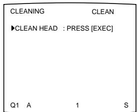
2 Press the EXEC button.
The printer starts cleaning the thermal head.
While cleaning, “Q1” which is displayed at the left bottom of the monitor is blinking. When the head cleaning is completed, “Q1” turns lit again.
When the END mark appears
The END mark is attached at the end of the cleaning ribbon. When this mark appears, rewind the cleaning ribbon up to its starting point, then reuse it.
To store the cleaning kit
Store a partially used cleaning kit in its original package so that dust will not accumulate.
Note
The surface of the thermal head is scraped away while cleaning. This results in quickening the wear of the thermal head. It is recommended that you avoid cleaning the thermal head frequently. Be careful so that dust or finger prints will not accumulate on the ink ribbon and paper.
Should the problem persist even if you clean the thermal head, contact your Sony dealer.
Cleaning the filter
We recommend the filter be cleared every three months.
1 Remove the fan cover from the printer, then remove the filter from the fan cover.
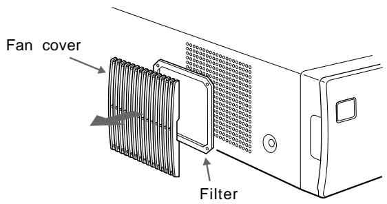
2 Clean the filter using a vacuum cleaner or the like.
Notes
- Be careful that the filter does not get caught inside the cleaner.
- Do not rub the net of the filter strongly.
3 Reset the fan cover and the filter, then mount them on the side panel as they were.
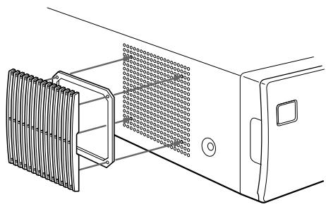
Both paper and an ink ribbon cartridge are necessary for printing. Use the ink ribbon with the paper contained in the same package.
UPC-510 Color Printing Pack
Contains color ink ribbon cartridge and paper.
Color ink ribbon cartridge 1 roll
A-5 (5^3 / 4 × 8^3 / 8 inches) size paper 200 sheets
Self-laminating Color Printing Pack UPC-540
Contains an ink ribbon cartridge and paper for automatic laminate coating.
Color ink ribbon cartridge 1 roll
A-5 size paper 102 sheets
Notes
- Use only the ink ribbon cartridge and paper designed for use with this printer. If you use a different type, the printer may not print properly or malfunction.
- Use the ink ribbon with the paper contained in the same package. Not doing so may result in degradation of the print picture quality and occurrence of a trouble. If the printer detects an incompatible combination, an error message appears in the printer window display.
- Ink ribbon and paper are not reusable. Once exhausted, replace them with new ones.
When you use the UPC-510 Color Printing Pack, 200 sheets of printouts can be printed for one ink ribbon roll. Even if you finish one pack of paper containing 100 sheets, do not throw away the ink ribbon. You can use the ink ribbon for an another pack of papers.
Power requirements
UP-51MDP: 220 to 240 V AC, 50 / 60Hz
UP-50/51MDU: 100 to 120 V AC, 50/60 Hz
UP-51MD: 100 to 120/220 to 240 V AC, 50 / 60Hz
Power consumption
UP-51MDP: About 1.2 A max. at 25^ , 240 V AC
UP-50/51MDU: About 2.8 A max. at 25^ , 120 V AC
UP-51MD: About 2.8 A max. at 25^ , 120 V AC
About 1.2 A max. at 25^ , 240 V AC
Operating temperature
5^ to 35^ (41^ to 95^)
Operating humidity
20% to 80% (no condensation allowed)
Storage and transport temperature
-20^ to 60^ (-4^ to 140^)
Storage and transport humidity
20% to 90% (no condensation allowed)
Dimensions About 370× 125× 490mm (w/h/d)
(1458× 5× 1938 inches)
Mass About 14.5kg (31 lb 15 oz)
Printing system
Sublimation heat transfer printing
11.6 dot/mm (2048 dots)
Total gradation
256 levels each for yellow, magenta, and cyan
Printing time Approximately 20 seconds (at color printing at high speed)
TV system Selectable with the NTSC/PAL selector (for UP-50/51MD/ 51MDP)
In NTSC mode: NTSC/EIA standards
In PAL mode: PAL B.G.I standards
Input connectors
RGB SYNC (analog RGB signal): BNC connector × 4
RGB: 0.7 Vp-p (75 ohm termination switch set to ON)
SYNC: 0.3 to 4 Vp-p
SYNC ON G: Automatic discrimination
75 ohms (75 ohm termination switch set to ON), sync negative
SVIDEO (Separate luminance (Y) and chrominance (C) signals):
4-pin mini-DIN × 1
Y:1 Vp-p
C: For NTSC/EIA standards: 0.29 Vp-p color burst
For PAL B.G.I standards:
0.3 Vp-p color burst
75 ohms (terminated), sync negative
VIDEO (NTSC composite video signal for NTSC/EIA standards and PAL composite video signal for PAL B.G.I standards): BNC connector × 1 1 Vp-p, 75 ohms (75 ohm termination switch set to ON), sync negative
AC IN (for power input)
Output connectors
RGB SYNC (analog RGB signal): BNC connector × 4
RGB: 0.7 Vp-p (75 ohm termination switch set to ON)
SYNC: 1 Vp-p
75 ohms (terminated), sync negative
SVIDEO (Separate luminance (Y) and chrominance (C) signals):
4-pin mini-DIN × 1
Y:1 Vp-p
C: For NTSC/EIA standards:
0.29 Vp-p color burst
For PAL B.G.I standards:
0.3 Vp-p color burst
75 ohms (75 ohm termination switch set to ON), sync negative
VIDEO (NTSC composite video signal for NTSC/EIA standards and PAL composite video signal for PAL B.G.I standards) BNC connector × 1 1 Vp-p, 75 ohms (terminated), sync negative
Controls connectors
REMOTE 1: special mini jack × 1 For RM-5500 Remote Control Unit (not supplied)
REMOTE 2 (automatic printing connector): Stereo mini jack: × 1 For RM-91 Remote Control Unit and FS-36 Foot Switch
REMOTE 3 (automatic printing connector): D-SUB 9-pin connector: × 1 For FS-30 Foot Switch (not supplied) (See "Selecting the Operation Mode for Automatic Printing Capabilities" page 104)
RS-232C (Computer control interface): D-SUB 25-pin connector × 1
Output: 5 kilohms at load Typical ± 8V
Input: 5-kilohm load
High level 5 to 15V
Low level -5 to -15V
Supplied accessories
Color printing pack (1)
Ink ribbon holder (1)
Paper tray (1)
Paper cover (1)
Fan cover with a filter (1)
Thermal head cleaning kit (1)
AC power cord (1)
Warranty card (1)
(for UP-50/51MD/51MDU)
Instructions for Use (1)
Optional accessories
UPC-510 Color Printing Pack
UPC-540 Self-laminating Color Printing Pack
Medical Specifications (for UP-51MD/51MDU/ 51MDP)
Protection against electric shock: Class I
Protection against harmful ingress of water: Ordinary
Degree of safety in the presence of flammable anesthetics or oxygen:
Not suitable for use in the presence of flammable anesthetics or oxygen
Mode of operation:
Continuous
Using the automatic printing capabilities (REMOTE 2/REMOTE 3)
If you send remote control pulse signals illustrated through the REMOTE 2 or REMOTE 3 connector, the printer is remotely controlled according to the remote control setting. (See page 104.)
Turn on the power of the printer and display the source image on the monitor screen. Send a remote control pulse signal at the timing shown below.
The timing depends on the setting on item IMMED. CAP of the FUNCTION SETUP menu.
Note
The remote control pulse signal examples introduced here are one example of typical operation timing. The timing may be affected due to the memory page selected and print type.
CAPTURE timing pulse for REMOTE 2
REMOTE 2 connector pin assignment:
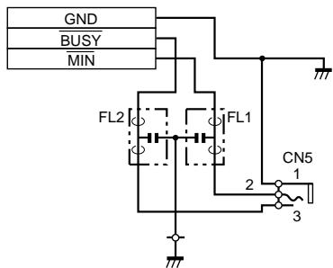
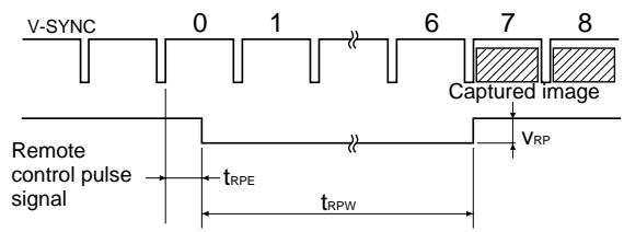
When IMMED. CAP. is set to OFF
| Notation | Parameter | MIN | TYP | MAX | Unit | Remarks |
| tRPE | Time within which a remote control pulse should be cleared to zero. | 3 | - | 12 | msec | - |
| tRPW | Length of a remote control pulse. | 100 | - | - | msec | - |
| VRP | Amplitude of a - remote control pulse. | - | - | 5 | V | This value is based on TTL standards. |
The above example shows that the images at the seventh and eighth positions are captured. However, images at another positions could be captured depending on the printer mode and printer settings.
Note
When AUTO LIVE of the FUNCTION SETUP menu is set to OFF, the memory image is displayed on the screen after the image is captured in memory. In such a case, whenever you capture an image, press the SOURCE/MEMORY button so that the source image appears on the video monitor. Displaying the memory image does not allow you to capture the image with the correct timing.
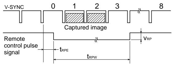
When IMMED. CAP. is set to ON
| Notation | Parameter | MIN | TYP | MAX | Unit | Remarks |
| tRPE | Time within which a remote control pulse should be cleared to zero. | 3 | - | 10 | msec | - |
| tRPW | Length of a remote control pulse. | 100 | - | - | msec | - |
| VRP | Amplitude of a - remote control pulse. | - | 5 | V | This value is based on TTL standards. |
Note
This mode is effective only when the source image is displayed on the monitor screen. If the memory image is displayed, the image will not be captured even if the pulse is sent to the printer. Be sure to display the source image when sending the pulse.
CAPTURE timing pulse for REMOTE 3
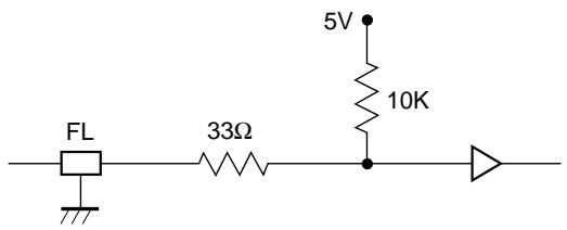
Input equivalent circuit
Output equivalent circuit
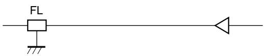
Pin assignment
| Pin | Signal | Remarks | |
| 1 | A | (Input) | TTL level |
| 2 | B | (Input) | TTL level |
| 3 | C | (Input) | TTL level |
| 4 | Reserved | (Input) | TTL level |
| 5 | Capture | (Input) | TTL level |
| 6 | GND | - | - |
| 7 | VD output | (Output) | TTL level |
| 8 | Light | (Output) | TTL level |
| 9 | Busy | (Output) | TTL level |
Input: Input the signal at the low level for more than 100 msec.
VD OUTPUT: The VD of the input signal currently selected is output.
Light: A high level signal is output when the printer is capturing the image in memory.
Busy: A high level signal is output when the printer can capture an image and can print. A low level signal is output when the printer cannot capture a) the image, when the printer cannot print, or when the printer neither can capture the image or print.
a) When the printer cannot capture the image: When an input signal already exists in the printer and the user wants to capture the image in a certain memory location, but cannot because the image stored in that memory location is being printed.
Note
When AUTO LIVE of the FUNCTION SETUP menu is set to OFF, the memory image is displayed on the screen after the image is captured in memory. In such a case, whenever you store the image, press the SOURCE/MEMORY button so that the source image appears on the video monitor. Displaying the memory image does not allow you to capture the image with the correct timing.
Design and specifications are subject to change without notice.
There are two kinds of messages: error messages and warning messages. This section lists these messages together with their possible causes and remedies. Note the messages and act accordingly.
Error Messages
If a problem occurs, the ALARM lamp lights orange and an error message stating the problem appears on the monitor and in the printer window display. In the error message introduced in the following tables, "nn" indicates the number or symbol displayed in the actual message.
| Message | Possible cause and remedies | |
| On the video monitor | In the printer window display | |
| INSERT RIBBON | INSERT RIBBON | The ink ribbon cartridge is not loaded. → Load the ink ribbon cartridge. (See page 9.) |
| SET PAPER | SET PAPER | • Paper has been exhausted. → Load the paper. (See page 12.) |
| RIBBON REMAIN 100 | RIBBON REMAIN 100 | • The paper tray is not installed. → Install the paper tray. (See page 12.) • When RIBBON REMAIN 0 is displayed, replace the ink ribbon. (See page 9.) |
| INSERT RIBBON AND PAPER | INSERT RIBBON | An ink ribbon cartridge and paper are not loaded. |
| SET PAPER | → Load the ink ribbon cartridge and paper. (See pages 9 and 12.) | |
| REMOVE PRINTS | REMOVE PRINTS | The maximum number of printouts has accumulated on the paper cover. → Remove the printouts from the paper cover. |
| REMOVE PAPER: TRAY | REMOVE PAPER | The paper jams around the paper tray as it is being fed into the ribbon area. |
| TRAY | → Remove any jammed paper. (See page 131.) | |
| CHECK RIBBON | CHECK RIBBON nn | • The ink ribbon has torn. → Repair the torn ink ribbon. (See page 12.) • An ink ribbon cartridge that can not be used with this printer has been loaded. → Load the appropriate ink ribbon cartridge. • The ink ribbon has been exhausted. → Replace the old one with a new ink ribbon cartridge. (See page 9.) (The ink ribbon cannot be reused.) |
| PAPER JAMMING | PAPER JAMMING nn | The paper has jammed inside the printer. → Check the position where paper has jammed and remove any jammed paper from the printer. (See page 131.) |
Continue to the next page
| Message | Possible cause and remedies | |
| On the video monitor | In the printer window display | |
| END OF RIBBON | END OF RIBBON | The ink ribbon has been exhausted. → Replace the old one with a new ink ribbon cartridge. (See page 9.) (The ink ribbon cannot be reused.) |
| MECHA TROUBLE: HEAD | MECHA TROUBLE nn HEAD | · The ink ribbon cartridge is not loaded correctly → Check the ink ribbon cartridge and load it correctly. (See page 9.) · The paper has jammed inside the printer. → Check the position where paper has jammed and remove any jammed paper from the printer. (See page 131.) |
| MECHA TROUBLE: TRAY | MECHA TROUBLE nn TRAY | The paper tray has moved out of position. → Contact your Sony service facility or your Sony dealer to clear the error status. |
| MECHA TROUBLE: PLATEN | MECHA TROUBLE nn PLATEN | The paper has jammed inside the printer. → Check the position where paper has jammed and remove any jammed paper from the printer. (See page 131.) |
| MECHA TROUBLE: LOAD | MECHA TROUBLE nn LOAD PAPER | |
| MECHA TROUBLE: EJECT | MECHA TROUBLE nn EJECT PAPER | |
| MECHA TROUBLE: CHUCK | MECHA TROUBLE nn CHUCK | |
Warning Messages
In case of a warning, only warning messages appear. The ALARM lamp does not light.
| Warning message | Possible causes and remedies | |
| On the monitor | In the printer window display | |
| HIT ANY KEY | HIT ANY KEY | This message appears when the remote control unit is used in CAP-STOP (CAPTURE STOP) mode and when the printer stops capturing images once images have been captured to all memory pages (to the last point of the last memory page). → Press any button. Printer operation is enabled after this. |
| INPUT MISMATCH | INPUT MISMATCH | · The TV system of the signal input from the source equipment (VTR, video camera and so on) is not compatible with the TV system of your printer. → Check the signal of the TV system and input the correct one. · An signal other than a video signal (such as an audio signal, etc.) is input. → Input the correct video signal. |
| NO INPUT | NO INPUT | The printer is not receiving an input signal from equipment corresponding to the input selected on the INPUT SETUP menu. → Check the input signal selected on the INPUT SETUP menu. (See page 14.) → Check whether the video equipment is outputting a video signal in playback mode. → Check that the connections between the signal source equipment and the printer are secure. (See page 74.) |
| NO IMAGE | NO IMAGE | The image is not captured in memory. → Capture the image in memory then start printing. (See page 19.) |
| PLEASE WAIT | PLEASE WAIT | In the selected memory page, the captured image is being printed or queued. |
| PRINTING MEMORY | PRINTING MEMORY | → Retry the operation once the printer finishes printing. |
| PLEASE WAIT | PLEASE WAIT | The thermal head has overheated. |
| HEAD IN COOLING | HEAD IN COOLING | → Leave the printer until the head cools down and this message disappears. The printer starts printing automatically. |
| PLEASE WAIT | PLEASE WAIT | The thermal head is being heated. |
| HEAD IN HEATING | HEAD IN HEATING | → Wait until this message disappears. The printer starts printing automatically. |
| PLEASE WAIT | PLEASE WAIT | The printer is printing, preventing any other operation. |
| NOW PRINTING | NOW PRINTING | → Wait until the printer finishes printing, then retry the operation. |
If the Paper Jams
If the paper jams after pressing the PRINT button, the message stating that paper has jammed appears on the video monitor and in the printer window display. Follow the steps below to remove the jammed paper.
1 Open the front panel.
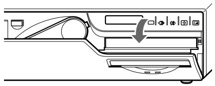
Continue to the next page
2 Remove the paper cover.
If any printouts have been ejected onto the paper cover and have accumulated on the paper cover, remove them before removing the paper cover.
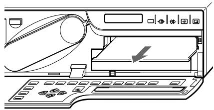
3 Check whether any paper is jammed inside the printer. If you find a jammed sheet, slowly pull it into the paper tray.
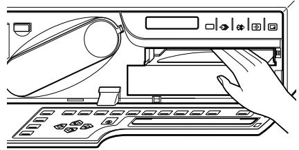
Note
Never attempt to pull a piece of jammed paper down, up, backwards, or forwards, the paper may tangle or tear.
4 Remove the paper tray.
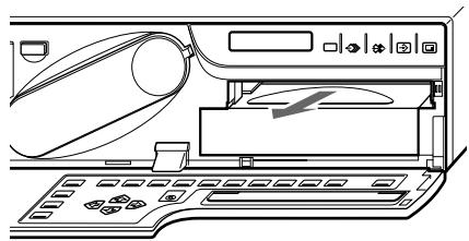
5 Load the paper into the paper tray correctly.
- Do not reuse the paper put back in step 3. Discard that paper.
- Use only paper recommended in this manual.
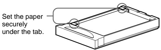
6 Re-insert the removed paper tray and paper cover, then close the front panel.
The following troubleshooting checks will help you correct the most common problems you may encounter with your unit. Before proceeding with these trouble checks, first check that the power cord is firmly connected. Should the problem persist, unplug the unit and contact your Sony dealer or local authorized Sony service facility.
| Symptoms | Possible causes and remedies |
| Nothing appears on the video monitor even if you press any of the operation buttons. | ·The POWER switch of the printer is not set to ON. →Set the POWER switch of the printer to ON. ·The POWER switch of the video monitor is not set to ON. →Set the POWER switch of the monitor to ON. ·Connections may not be correct. →Check connections and rectify, if necessary. (See page 75.) |
| No message appears on the regular screen. | An incorrect signal is input. →Select another input signal by pressing the INPUT SELECT button. (See page 14.) Or, set the connected video equipment to playback mode, if it is currently set to another mode such as stop mode. →In this case, first check the video monitor by pressing the SOURCE/MEMORY button to display the image stored in memory. If an image appears, the monitor is working correctly. |
| No message or image appears on the regular screen. | ·If an image captured in memory appears when the SOURCE/MEMORY button is pressed, SOURCE on the OUTPUT SETUP menu is set to THRU. →Change the SOURCE setting to EE. (See page 84.) ·When the menu is displayed by pressing the MENU button, the DISPLAY setting of the video monitor is set to OFF. →Set the DISPLAY setting to ON by pressing the DISPLAY button. (See page 68.) |
| No message appears in the printer window display. | ·The contrast of the printer display window is not set correctly. →Adjust the brightness of the printer window display using the LCD. CNTR. item on the SYSTEM OUTPUT menu. (See page 110.) ·The contrast of the printer display window is set to OFF. →Adjust the brightness of the printer window display using the LCD. CNTR. item on the SYSTEM OUTPUT menu. (See page 110.) |
| The printer does not print. | ·An error message appears on the display. →Perform the steps described in "Error/Warning Messages" on page 129. ·Paper that cannot be used with this printer has been loaded. →Load the correct paper. Use only ink ribbons and paper for this printer. (See page 124.) ·The paper is not loaded correctly. →Check which side of the paper is the printing side, then load the paper again. (See page 12.) |
| A black line appears on the printout. | Any portion for which there is no signal is printed in black. →Shift the printout area. Capture a new image and print it. (See page 96.) |
| The printer produces a printout with a black frame. | Any portion for which there is no signal is printed in black. →Make the printout size narrower. Capture a new image and print it. (See page 96.) |
| The printed image is partially cut out. | Only part of the video signal has been stored. →Make the printout size wider. (See page 96.) Capture a new image and print it. |
| The printout is blurred. | A quickly moving image has been stored. →Set the memory mode to FIELD by using the MEMORY FRM/FLD button, then print it. (See page 33.) |
| The printout color is very pale. | The paper is not loaded correctly. →Check which side of the paper is the printing side, then load the paper again. (See page 12.) |
Continue to the next page
| Symptoms | Possible causes and remedies |
| The ink ribbon cartridge cannot be inserted. | An ink ribbon cartridge that can not be used with this printer is used. → Insert the appropriate ink ribbon cartridge. (page 9) |
| The video monitor screen is too bright and the contrast in the light area is weakened. | The 75-ohm termination switch is set to the wrong position. → Set 75-ohm termination switch to the correct position. (page 74) |
| The video monitor screen is dark. |
For details, refer to the pages given in parentheses.
Main Panel
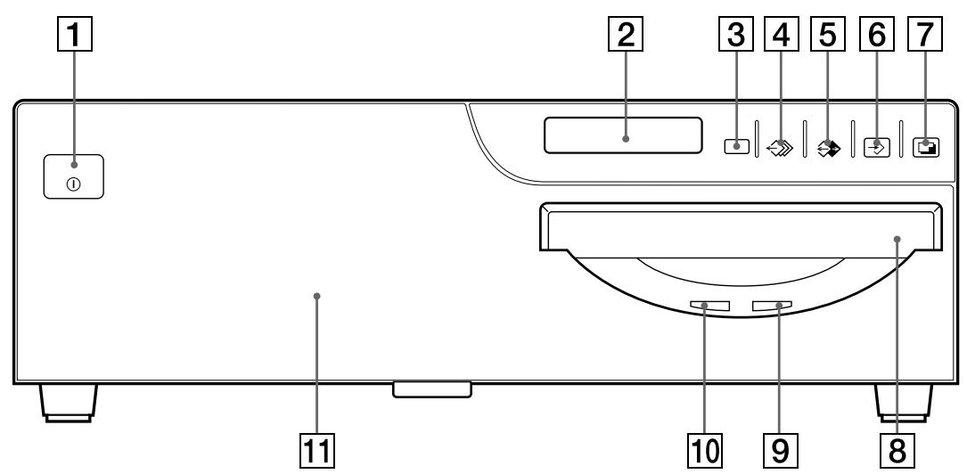
1 ① POWER switch
Press to turn the printer on or off.
2 Printer window display
Displays messages that also appear along the bottom edge of the monitor screen. Also displays the menu screen line at which the cursor is positioned. If an error occurs, a corresponding error message is displayed. The contrast of the printer window display can be adjusted on the SYSTEM SETUP menu. Also, the printer window display can be cleared on the SYSTEM SETUP menu.
Remote sensor
Aim the head of the remote control unit toward this sensor.
4 MEMORY PAGE button (26, 39, 67)
Press to select the memory page.
5 SOURCE/MEMORY button (44, 67, 78, 98)
Press to select which signal is to be output to the monitor.
The memory image and source image are toggled each time you press this button.
6 CAPTURE button (18, 26, 44, 51, 52, 100)
Press to capture an image in a memory page.
7 PRINT button (19, 26, 51, 53, 63)
Press to make a printout.
8 Paper ejection slot
The printout is ejected here.
9 PRINT lamp
Lights while the printer is printing.
10 ALARM lamp (129)
Lights in orange when the ink ribbon or paper is exhausted, the paper jams, or another problem occurs.
1 Front door
Pull the top on the front door toward you to open it.
Opening the front panel reveals the sub panel buttons, ink ribbon cartridge, paper tray and paper cover.
Continue to the next page
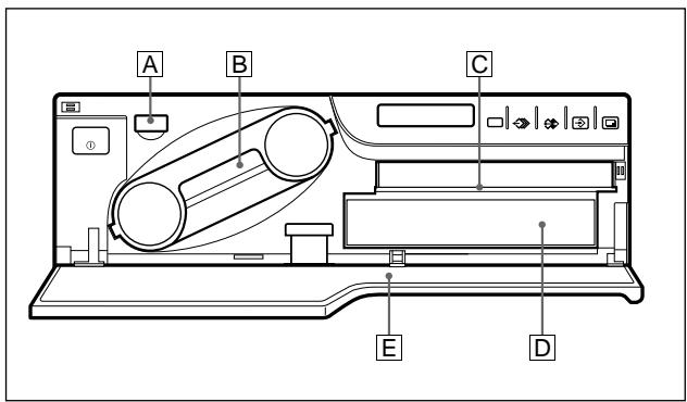
When the front panel is open
A EJECT button (10)
Press to eject the ink ribbon cartridge.
B Ink ribbon cartridge (9, 71)
Insert the ink ribbon cartridge.
C Paper cover (71)
Paper is ejected onto this cover.
D Paper tray (13, 71)
Load paper into this tray.
E Sub panel keys
For details, see "Sub Panel"
Sub Panel
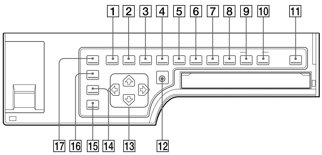
1 MENU button
Press this button to display or clear the menus on the screen and printer window displays.
2 LOAD USER button (21, 118, 119)
Press this button to recall a registered user set. Pressing this button causes the currently selected user set to be is displayed for about three seconds. To recall another user set, release the button while the desired user set number is displayed. Each time you press this button, user set is switched in the order of 1, 2, 3.
3 MULTIPICTUREbutton(36,52)
Press this button to select the desired printout type on the regular screen. When you press this button, the currently selected printout type is displayed for about three seconds. Each time you press this button, the type is switched in the order of 1, 2, 4, 8, 16, 1.... The setting of MULTIPIX on the LAYOUT SETUP menu changes linked with this button setting.
4 PRINT QTY (quantity) button (23)
Press this button to set the number of copies on the regular screen. You can set any number up to 9. When you press this button, the currently selected number is displayed for about three seconds. The setting of PRT QTY
on the PRINTER SETUP menu changes linked with this button setting. You can change the number even when the printer is printing.
5 RIBBON REMAIN button (20, 69)
Press this button to display the type and the number of printouts that can still be made on the regular screen. To not display them, press this button again. The setting of RBN REMAIN on the OUTPUT SETUP menu changes linked with this button setting.
6 INPUT SELECT button (14)
Press this button to select the input signal on the regular screen. When you press this button, the currently selected input signal is displayed for about three seconds. To select the input signal, release the button while the desired input signal is displayed. Each time you press this button, the input signal is switched in the order of VIDEO, RGB, S-VIDEO, RGB...
7 MEMORY FRM/FLD button (18, 33)
Press this button to select the memory mode on the regular screen. When you press this button, the currently selected memory mode is displayed for about three seconds. To select the memory mode, release the button while the desired memory mode is displayed. Each time you press this button, the memory mode is switched in the order of FRAME, FIELD, FRAME.
To make a printout of a captured image which is blurred, set the memory mode to FIELD and eliminate the blur by pressing this button, and then make a printout.
8 MOTION CHECK button (46, 47)
Press this button to select the mode on the regular screen to check whether the memory images are blurred when you captured two- or four-reduced images. Each time you press this button, the type is switched in the order of ON, OFF, ON... The setting of MOTION CHK on the PRINTER SETUP menu changes linked with this button setting.
9 CAPTION INPUT button (56)
Press this button to display or clear the CAPTION menu on the regular screen.
10 CAPTION ON/OFF button (63)
Used to determine whether a caption is printed on the printout. To make a printout with a caption, press this button to display ON. To make a printout without a caption, press this button to display OFF.
11 CLEAR button (66, 67)
Press this button to clear the images captured in the memory pages. Which images can be cleared with the CLEAR button depends on the setting made with the FUNCTION SETUP menu.
When the clear function of this button is set to OFF, the buzzer sounds if you press the CLEAR button.
12 EXEC button (57, 91, 97, 101, 117, 118, 119)
Press this button to execute the values set with the COLOR ADJUST menu or to recall a user set in the PRINTER SETUP menu and to register the user set in the SYSTEM SETUP menu. Also, this button is used to enter the characters of a caption in the CAPTION menu.
13 Cursor keys
Use to select a desired item from the menu. Also, these keys are used to position the cursor (green pointer) on the regular screen when capturing multiple reduced images.
14 INPUT SETUP button (16, 79)
Press this button to display the INPUT SETUP menu on the regular screen.
15 DISPLAY button (20, 68, 100)
When the regular screen is displayed, pressing this button toggles the screen display on and off of (messages such as, Q1, A, etc.) regardless of the setting of the DISPLAY item in the OUTPUT SETUP menu. The setting of DISPLAY in the OUTPUT SETUP menu changes linked with this button.
When the menu is displayed, pressing this button temporarily clears the menu display. While this button is held down, the menu display disappears.
16 R/G/B/D/L button (86)
Press this button to display or clear the COLOR ADJUST menu on the regular screen.
17 LOAD COLOR button (87)
Press this button to recall the values set for the printout color (color intensity and color contrast). Pressing this button causes the
currently selected LOAD COLOR number to be displayed for about three seconds. Three kinds of LOAD COLOR numbers are available for the currently selected user set. To select the desired LOAD COLOR number, release the button while the desired LOAD COLOR number is displayed.
The selected LOAD COLOR number in the COLOR ADJUST menu changes linked with this button.
Rear
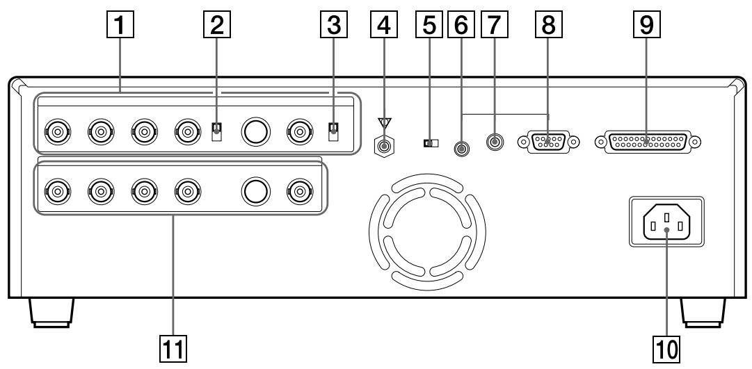
1 INPUT (input signal) connectors (74)
Used to connect the video equipment supplying the source image.
| Connector | Connectable equipment |
| S-VIDEO | Video equipment with Y/C separated output connector |
| VIDEO | Video equipment with composite video signal output connector |
| RGB SYNC | Video equipment with RGB/SYNC output connectors |
2 75Ω ON/OFF termination switch (74)
Provided for the RGB input.
Normally set this switch to ON. Set it to OFF if the input signal should drop when you connect additional equipment to the video equipment.
3 75ΩON/OFFtermination switch(74)
Provided for the NTSC composite video signal in NTSC mode and PAL composite video signal in PAL mode.
Normally set this switch to ON. Set it to OFF if the input signal should drop when you connect additional equipment to the video equipment.
4 Equipotential ground terminal connector
Used to connect to the equipotential plug to bring the various parts of a system to the same potential.
Refer to "Important safeguards/ notices for use in the medical environments" for UP-51MD/ 51MDU/51MDP on page 2.
5 NTSC/PAL (NTSC/PAL TV) selector (74, 75) (only for models other than UP-51MDU)
Set this selector according to the TV system of the input signal. If you change this setting, turn the printer power off, then back on again.
| Selector position | When |
| NTSC | The NTSC system video equipment is connected. |
| PAL | The PAL system video equipment is connected. |
6 REMOTE 1 connector (special mini jack) (76)
Used to connect the RM-5500 Remote Control Unit (not supplied) to be used as a wired remote control unit.
7 REMOTE 2 connector (stereo mini jack) (76)
Used to connect the RM-91 Remote Control Unit (not supplied), or the FS-36 Foot Switch.
8 REMOTE 3 connector (D-SUB 9-pin) (76)
Used to connect the FS-30 Foot Switch. Or input remote control pulse signals for automatic printing.
RS-232C connector (76)
Used to connect the computer to control the printer. For details, contact your nearest Sony dealer.
10 AC IN connector
Used to connect the printer to a wall outlet with the supplied power cord.
11 一 OUTPUT connectors (75)
Used to connect the video monitor.
Refer to "Important safeguards/ notices for use in the medical environment" for UP-51MD/ 51MDU/51MDP on page 2.
| Connector | Connectable equipment |
| S-VIDEO | Video monitor with Y/C separated input connector. |
| VIDEO | Video monitor with composite video signal input connector |
| RGB SYNC | Video monitor with RGB/SYNC input connectors. |
Comparing the Printer Window Display with the Video Monitor Display
You can operate the printer using either the printer window display or the video monitor display. The printer window display has a narrower display range and show only a limited number of characters. Use whichever method you prefer.
Regularscreen
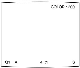
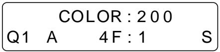
Monitor Display
There are two types of display: a regular screen display and a menu screen display. The two types of display are explained using the monitor display.
Regular screen display
When you first turn on the printer, the regular screen message appears.
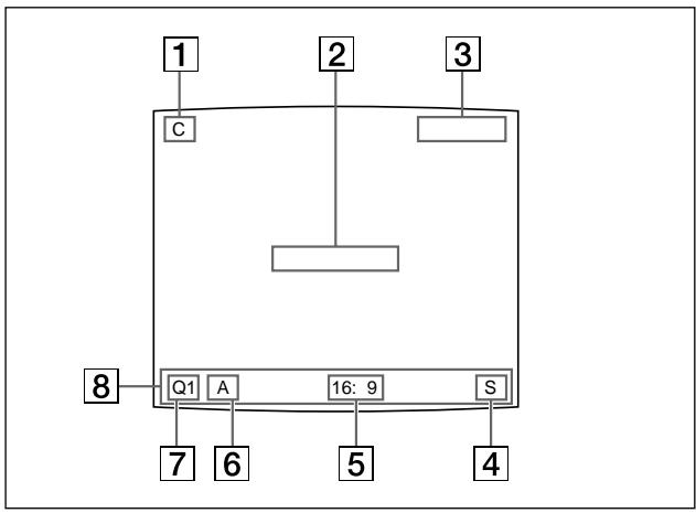
C (Caption) display section
C is displayed in white when the printer is set to print a caption.
2 Message display section
Messages are displayed.
3 Ink ribbon type and remaining amount of ink ribbon display section
Displays the ink ribbon type and the remaining amount of ribbon (indicates the number of printouts that can still be made with the ribbon) when the ribbon remaining display function is set to ON.
4 S or M (image type) display section
Indicates the type of image being displayed on the monitor screen.
S (Source): The image from the input signal source is displayed on the screen.
M (Memory): The image stored in memory is displayed on the screen.
5 Printer operation mode display section
Indicates the printer application mode (STANDARD or DUPLICATE) or type of printouts such as multiple reduced images.
Examples:
1: Indicates that full-size image and the STANDARD mode are selected.
4: Indicates that four-reduced images and the STANDARD mode are selected
16F: Indicates that 16-reduced images with white borders and the STANDARD mode are selected. When SEPARATE (image with white borders) is set to ON on the LAYOUT SETUP menu, F is attached.
DUP1: Indicates that full-size image and the Duplicated mode are selected.
DUP4: Indicates that four-reduced images and the Duplicated mode are selected.
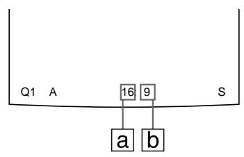
a: Indicates the type of printout
b: Indicates the position where the cursor is currently placed and where an image will be captured.
6 Memory page display section
Indicates the currently selected memory page. While the image in the memory page is being printed, the memory page indication blinks in green. The memory page whose memory image is queued to be printed blinks in white.
Q (print quantity) display
Indicates the number of copies to be printed. This item blinks while the printer is busy.
8 Printer setting status display section
The corresponding currently selected status is displayed when one of the LOAD USER,LOAD COLOR,MULTI PICTURE,PRINT QTY,INPUT SELECT,MEMORY FRM/ FLD,DISPLAY,RIBBON REMAIN or CAPTION ON/OFF buttons is pressed.
Menu screen tree chart
The menu screen configuration is shown using a tree-chart. For details, refer to the pages indicated in ( ).
COLOR ADJUST menu (86)
COLOR ADJUST COLOR:200
/COL/LAY/PRN/IN/OUT/
LAYOUT SETUP menu (34, 37, 49, 53, 114)
LAYOUT SETUP COLOR:200
COL/LAY/PRN/IN/OUT/
MEMORY : FRAME / FIELD
MULTIPIX :1/2/4/8/16
SEPARATE : OFF / ON
MIRROR : OFF / MIRROR
LAMINATION : GLOSSY /
WINDOW : PRESS [>]
CAPTION : PRESS [>]
Q1 A 1 S
PRINTER SETUP menu (24, 29, 40, 48, 92)
PRINTER SETUP COLOR:200
COL/LAY/PRN/IN/OUT/
PRINT QTY. :1 [1~9]
INTERVAL : OFF/ON
GAMMA : S / NORMAL / H
PRN SPEED : /HIGH
MOTION CHK : OFF / ON
LOAD USER :1/2/3 [EXEC]
SYSTEM :PRESS[>]
FUNCTION :PRESS [> ]
C-BALANCE :PRESS [>
11 A 1
INPUT SETUP menu (16, 78)
INPUT SETUP COLOR:200
COL/LAY/PRN/IN/OUT/
INPUT SEL :VIDEO/SV/R
HUE :0
COLOR :0
GAIN :0
OFFSET :0
AGC : OFF/ON
Q1 A 1 S
OUTPUT SETUP menu (68, 69, 76, 83, 84)
OUTPUT SETUP COLOR:200
COL/LAY/PRN/IN/OUT
DISPLAY :OFF/ON
RBN REMAIN: OFF/ON
SOURCE : THRU / EE
SYNC ON G:OFF/ON
MONIC-B 0
MONI M-G :0
MONI Y-B :0
Q1 A 1 S
WINDOW SETUP menu (96)
WINDOW SETUP COLOR:200
LAYSETUP :PRESS[>]
H START 0 DOT (S)
V START 0 DOT (S)
HWIDTH :896 DOTS
VWIDTH : 464 DOTS
SAVE :PRESS [ EXEC ]
CANCEL :PRESS [EXEC]
Q1 A 1 S
CAPTION menu (55, 57)
CAPTION OFF 1
ABCDEFGHJKLMN
OPQRSTUVWXYZ
0123456789+--=%
”,.:()[}{}<
1?&/ * # $¥ £@ - |'
INS DEL SP ON EXIT
Q1 A 1 S
SYSTEM SETUP menu (31, 81, 110, 111, 112, 116)
SYSTEM SETUP COLOR:200
PRN SETUP:PRESS[>]
LCD-CNTR 7
BAUDRATE : /24/48/9600
BEEP : OFF/ON
APPLI. STANDARD/
IRE :100/11/12/13
SAVE USER :1/2/3 [EXEC]
USER NAME:PRESS[>]
Q1 A 1 S
USER NAME input menu (116)
USER NAME 1
ABCDEFGHIJKLMN
OPQRSTUVWXYZ
0123456789+-=%
" ", . ; : ( ) [ ] {} < >
!? & / * # $¥£ @ ~ |'
INS DEL SP EXIT
FUNCTION SETUP menu (42, 64, 104, 105)
FUNCTION SETUP COLOR:200
PRN SETUP :PRESS [>]
AUTO LIVE : OFF / ON
IMMED.CAP.:OFF/ON
RM2 FUNC :/ C&PRINT /
RM3A FUNC :/PRINT&PAGE
RM3B FUNC :/ BACK - SP /
RM3C FUNC :/ CAP/SRC
RM3E FUNC :/ GRAB
CLEAR :/ALL
Q1 A 1 S
COLOR BALANCE menu (98)
COLOR BALANCE COLOR:200
PRN SETUP:PRESS[>]
BAL X :50[1-50-99]
BAL Y :50[1-50-99]
BAL STEP :05 [1-20]
TEST PRINT:PRESS [EXEC]
Q1 A 1 S
A,B
Accessories (supplied) 71
Adjusting
brightness of the printer window display 110
color balance 98
color of the input signal 78
color of the printer's output signal 83
level of the input signal 81
interpolation 90
printout area 96
printout color 86
printout size 96
printout tone 92
sharpness of the printout 89
Assembly 72
Automatic printing
pulse signal 126
selecting operation mode 104
Baud rate for computer
communication 113
Blur
checking blur from the memory image 46
eliminating from the printout 18
C
Caption
CAPTION menu 55
entering 57
making a printout with
a caption 63
Changing the printout size/printout
area 94
Cleaning
cabinet 121
filter 123
thermal head 122
COLOR ADJUST menu 86
COLORBALANCEmenu98
Color printing pack 124
Condensation precautions 120
Connections
for enabling remote control 76
for storing video images 74
for viewing images to be printed
on the video monitor 75
D
Deleting the images stored in memory pages
deleting all images stored in the printer 66
deleting images in a certain memory page 67
setting the function of the CLEAR button to be used for deleting images 64
Display
erasing screen display 68
monitor display 138
type and remaining amount of the ink ribbon 69
E
Eliminating the blur 18
Entering a caption
adding characters mid ways 60
entering a caption 57
entering a space 60
replacing a previously entered character 60
when you enter a wrong
character 59
Error messages 129
F, G, H
Foot switch 73, 76, 104
Full-size image printout
making 17
setting 36
FUNCTION SETUP menu 42,64, 104,105
I, J, K
Ink ribbon and paper 124
Ink Ribbon cartridge
loading 9
if your ink ribbon should tear 12
notes on storing 12
removing 9
Installation precautions 120
L
Lamination pattern
selecting 114
self-laminating color printing pack 124
LOAD COLOR number
recalling 91
storing 91
Loading an ink ribbon cartridge 9
Loading paper 12
Location and function of parts and controls
main panel 135
monitor display 140
rear 138
sub panel 136
Location precautions 121
M, N, O
Memory page
selecting the memory page 39
usable memory page 38
Menu
CAPTION menu 55, 57
COLOR ADJUST menu 86
COLORBALANCEmenu98
FUNCTION SETUP menu 42, 64, 104, 105
INPUT SETUP menu 16, 78
LAYOUT SETUP menu 34, 37, 49, 53, 114
OUTPUT SETUP menu 68, 69, 76, 83, 84
PRINTER SETUP menu 23, 30, 41, 48, 49
SYSTEM SETUP menu 31,81, 110,111,112,116
USER NAME input menu 116
WINDOW SETUP menu 96
Menu screen tree chart 141
Mirror image 53
Monitor display 140
Output signal of the printer 83
P, Q
Paper
ink ribbon and paper 124
loading 12
notes on storing 13
removing the jammed paper 131
Paper jams 131
Precautions
cleaning 121
condensation 120
installation 120
safety 120
thermal head 122
transportation 121
Print quantity setting 23
PRINTER SETUP menu 23, 30, 41, 48, 49
Printing at high speed 19
eliminating the blur 18
if a black line appears on the printout 20
if the image quality of printouts is not satisfactory 20
if the paper runs out during printing 25
if the printer does not print 19
if the stored image is blurred 18
making a full-size image printout 17
making a printout of multiple reduced images 35
making a printout of identical reduced images 50
making a printout of a mirror image 53
making a printout with a caption 63
making a printout with an insert 52
making printouts with white borders 49
printing remotely 73
selecting the memory page 39
selecting the printout type 35
storing another images while printing 26
Printing pack 124
Printout area 96
Printout color color intensity 88
contrast 89
interpolation for the image data 90
LOAD COLOR number 86
sharpness 89
Printout size 96
Printout quality
adjusting the printout color 86
adjusting the sharpness 89
compensating for the input signals 78
eliminating the blur 18
Printouts
with a black line 96
with black frame 96
partially cut 96
notes on storing 20
Printouts variations 7, 28
Pulse signals 127
R, S
Remote control unit (not supplied)
foot switch 73, 76, 104
remote control unit 73, 76, 104
Safety precautions 120
Screen display
erasing 68
erasing menu temporarily 69
Selecting the input signal 14
Setting up the printer with menu
adjusting the printer window display brightness 110
adjusting the printout color 86
adjusting the sharpness 89
changing the printout area/ printout size 94
compensating for the input signal 78
displaying the type and remaining
amount of the ink ribbon 69
erasing the screen display 68
selecting operation mode for automatic printing capabilities 104
selecting whether to enable the operation and error tones 112
setting baud rate for computer communication 113
setting the lamination pattern 114
Sharpness 89
Specifications 125
Supplied accessories assembly 72
supplied accessories 71
System configuration 8
System overview 7
SYSTEM SETUP menu 31,81, 110,111,112,116
T to W
Thermal head
cleaning 122
secure 121
unlock 121
Troubleshooting 133
User set
printing with the desired user set 21
recalling 21, 118
registering 116
Using the automatic printing capabilities 104
Warning messages 130
AVENTISSEMENT
UP-50
UP-51MD
UP-51MDU
UP-51MDP
FUNCTION SETUP PRN SETUP [> ]
INTERPOL. (Interpolation)
UP-50
UP-51MD
UP-51MDU
UP-51MDP
FUNCTION SETUP PRN SETUP [> ]
INTERPOL. (Interpolation)
FUNCTION SETUP PRN SETUP [> ]
1 Vp-p, 75 Ohm (75-Ohm
(fur UP-50/51MD/51MDU)
2 Taste LOAD USER (305,402,403)
CAPTION, Menu 339, 341
COLOR ADJUST, Menu 370


- WARNING
- For UP-51MD/51MDU/51MDP
- Symbol on the products
- For the customers in the U.S.A.
- Important safeguards/ notices for use in the medical environments (for UP-51MD/51MDU/ 51MDP)
- Caution
- For the customers in Canada (for UP-51MD/51MDU)
- Installation and Adjustment
- Setting Up the Printer 77
- Others
- Precautions 120
- Ink Ribbon and Paper 124
- Specifications 125
- Error/Warning Messages 129
- Troubleshooting 133
- Location and Function of Parts and Controls 135
- Index 142
- Organization of this manual
- Introduction
- Operation
- Conventions used
- Cross references
- Important note
- Index
- Monitor and printer window displays
- Printouts that can be made with the printer
- System Configuration
- Notes
- Loading an Ink Ribbon Cartridge
- Note
- When the ink ribbon cartridge cannot be ejected
- Load the new ink ribbon into the ink ribbon holder.
- Remove any slack from the ink ribbon.
- Insert the ink ribbon cartridge firmly until it clicks.
- When the ink ribbon cartridge cannot be inserted
- Close the front panel.
- When storing ink ribbon cartridge:
- If your ink ribbon should tear
- Loading Paper
- When handling the paper
- When storing the paper
- Selecting the Input Signal
- Selecting the input signal by using the INPUT SELECT button
- Select the desired input signal.
- To confirm the currently selected input signal
- Selecting the input signal on the menu
- Before making a full-size image printout
- If the captured image is blurred
- To change the image captured in memory
- Press the PRINT button.
- To stop printing
- If the printer does not print
- To make a printout at high speed
- When you want to see an image that is hidden below a screen message
- If a black line appears on the printout
- If the color quality of printouts is not satisfactory
- When storing your printouts:
- Making Printouts with the Desired User Set Number
- Making Multiple Copies of Identical Printouts
- Setting the printout quantity
- To set the printout quantity by using the PRINT QTY button
- To decrease the number of copies
- Setting the printout quantity using the menu
- If the paper runs out during printing
- Capturing Another Image While Printing
- Variations of printouts that the printer can produce
- Selecting the Printer Application Mode
- Press the button.
- Select APPLI. by pressing the or button.
- Select the desired application mode by pressing the or button.
- Select PRN SETUP by pressing the or button.
- Press the button.
- Press the MENU button.
- About the Memory
- In frame mode
- In field mode
- Selecting the memory mode
- To select the memory mode using the MEMORY FRM/FLD button
- To select the memory mode using the menu
- Making a Printout of Multiple Different Reduced Images
- Selecting the number of reduced images to be captured in memory
- To select the desired type of reduced images to be captured in memory using the MULTI PICTURE button
- Press the MULTI PICTURE button.
- Select the type of reduced images to be captured in memory by pressing the MULTI PICTURE button.
- To select the type of reduced images to be captured in the memory using the menu
- Selecting the memory page
- To select the memory page
- Selecting the method to be used to capture the images
- Select INTERVAL by pressing the or button.
- Select the desired method for capturing images by pressing the or button.
- Select FUNCTION by pressing the or button.
- To return to the PRINTER SETUP menu
- Making a Printout with multiple reduced images
- Before making the printout of four reduced images
- Start the video source.
- To replace a captured image
- To skip a previously captured image
- Press the PRINT button.
- If the printout is blurred
- To confirm whether the captured images are blurred on the video monitor
- To set the MOTION CHECK function using the MOTION CHECK button
- Press the MOTION CHECK button.
- Select the desired setting by pressing the MOTION CHECK button.
- To select the setting using the menu
- Making a printout with white borders
- Making a Printout of Identical Reduced Images
- Before making the printout of identical reduced images
- Press the CAPTURE button at the instant the image you want to print appears on the screen.
- To change the image in memory
- Press the PRINT button.
- Making a Printout with an Insert
- Making a Printout of Mirror Images
- Select MIRROR by pressing the or button.
- Select whether the captured images are to be rotated or not.
- Press the MENU button.
- About the CAPTION menu
- Symbols and words can be used to enter a caption
- Displaying the CAPTION Menu
- To display the CAPTION menu by using the LAYOUT SETUP menu
- Entering a Caption
- To move the cursor
- To select either capital letters or small letters
- Press the EXEC button.
- When you enter the wrong character in the above example
- To enter a space
- To replace a previously entered character without changing the number of characters
- To add characters midway
- To make printouts with a caption
- Making printouts with a caption
- Press the CAPTION ON/OFF button.
- Select ON.
- To make a printout without a caption
- Setting the Function of the CLEAR Button
- Press the button.
- Select CLEAR by pressing the or button.
- Select the function of the CLEAR button by pressing the or button.
- Select PRN SETUP by pressing the or button. Then, press the button. The PRINTER SETUP menu appears.
- To return to the regular screen
- Deleting Images Stored in Memory
- Deleting images in all memory pages simultaneously
- Before deleting images in all memory pages
- Deleting images in a certain memory page
- Before deleting images
- Erasing the Screen Display on the Video Monitor
- Press the DISPLAY button.
- Select OFF.
- To display characters on the video monitor
- To perform the setting for the monitor display on the menu
- When you want to see an image that is hedden below a menu
- Displaying the Type and Remaining Amount of the Ink Ribbon
- Press the RIBBON REMAIN button.
- To erase the information about the ink ribbon
- To perform the setting for the display of ink ribbon information using the menu
- Assembly
- To attach the paper cover, paper tray and ink ribbon cartridge
- To attach the fan cover and the filter
- Preparing the Remote Control Unit
- Using the RM-5500 remote control unit
- To use the RM-5500 remote control unit (not supplied) as a wireless unit
- Using the RM-91/FS-30/FS-36
- Making Connections for Capturing Video Images
- Making Connections for Viewing Images to be Printed
- When connecting the video monitor to the RGB SYNC OUTPUT connectors
- Making Connections to Enable Remote Control
- Compensating for the Input Signals
- Press the INPUT SETUP button in the sub panel.
- Perform the adjustments as follows.
- When the printout or monitor image appears blackish or whitish
- To reset items to defaults (0)
- Press the MENU button.
- Compensating for the level of the input signal
- Select IRE by pressing the or button.
- Select the desired IRE value by pressing the or button. The selected IRE is displayed in three digits.
- Press the MENU button. The regular screen appears.
- Matching the Video Monitor Color to the Printer Color
- Adjustment on the video monitor
- Adjustment on the printer
- Adjust the monitor while comparing the printout with the image on the monitor.
- Press the MENU button.
- Adjusting the Printout Color
- Adjusting the color intensity, contrast and sharpness
- Select LOAD COLOR by pressing the or button.
- Select the LOAD COLOR number of the values to be adjusted or to be modified by pressing the or button.
- Adjust the printout color.
- When adjusting DARK/LIGHT (contrast)
- When adjusting the sharpness SHARPNESS
- INTERPOL. (Interpolation)
- Once you have changed the value
- Select SAVE COLOR by pressing the or button.
- To retain the originally set value
- To copy the settings made for one LOAD COLOR number to another LOAD COLOR number
- To recall the LOAD COLOR number in which printout color settings (color intensity, contrast and sharpness) are stored
- Adjusting the tone of the printout
- Changing the Printout Size/Printout Area
- Select WINDOW by pressing the or button.
- Press the button.
- Adjust the printer according to the printout obtained.
- When a black frame is printed or the image is partially cut
- When a black line appears on the printout
- To clear the adjusted value
- To reset the adjusted value to defaults
- To check the adjustment result
- Adjusting the Color Balance
- Before adjusting the color balance
- Select C-BALANCE by pressing the or button.
- To reset the values to defaults (50/50/05)
- Press the EXEC button.
- Example of the actual color change in the test print
- Select the image which has the best color balance among the nine images.
- To readjust the color balance
- To perform fine adjustment
- To perform rough adjustment
- Selecting the Operation Mode for Automatic Printing Capabilities
- Select FUNCTION by pressing the or button.
- Press the button. The FUNCTION SETUP menu appears.
- Select IMMED. CAP by pressing the or button.
- Adjusting the Brightness of the Printer Window Display
- Select LCD-CNTR by pressing the or button.
- Adjust the brightness of the printer window display by pressing the or button.
- Select PRN SETUP by pressing the or button, then press the button. The adjusted values are stored. The PRINTER SETUP menu appears.
- Press the MENU button.
- Selecting Whether the Operation and Error Tones Sound
- Setting the Baud Rate for Computer Communication
- Selecting the Lamination Pattern
- Registering a User Set
- Press the EXEC button.
- To make another user set
- To recall the user set and print
- To retain the originally set values
- To copy the existing user set
- Safety
- Installation
- Condensation
- Location
- Before Transporting the Printer
- To release the thermal head
- Cleaning
- Cleaning the cabinet
- Cleaning the thermal head
- When the END mark appears
- To store the cleaning kit
- Cleaning the filter
- UPC-510 Color Printing Pack
- Self-laminating Color Printing Pack UPC-540
- Using the automatic printing capabilities (REMOTE 2/REMOTE 3)
- CAPTURE timing pulse for REMOTE 2
- REMOTE 2 connector pin assignment:
- CAPTURE timing pulse for REMOTE 3
- Error Messages
- Warning Messages
- If the Paper Jams
- Main Panel
- Sub Panel
- RIBBON REMAIN button (20, 69)
- INPUT SELECT button (14)
- MEMORY FRM/FLD button (18, 33)
- MOTION CHECK button (46, 47)
- CAPTION INPUT button (56)
- CAPTION ON/OFF button (63)
- CLEAR button (66, 67)
- EXEC button (57, 91, 97, 101, 117, 118, 119)
- Cursor keys
- INPUT SETUP button (16, 79)
- DISPLAY button (20, 68, 100)
- R/G/B/D/L button (86)
- LOAD COLOR button (87)
- Rear
- INPUT (input signal) connectors (74)
- 75Ω ON/OFF termination switch (74)
- 75ΩON/OFFtermination switch(74)
- Equipotential ground terminal connector
- Comparing the Printer Window Display with the Video Monitor Display
- Monitor Display
- Regular screen display
- Menu screen tree chart
- COLOR ADJUST menu (86)
- LAYOUT SETUP menu (34, 37, 49, 53, 114)
- PRINTER SETUP menu (24, 29, 40, 48, 92)
- INPUT SETUP menu (16, 78)
- OUTPUT SETUP menu (68, 69, 76, 83, 84)
- WINDOW SETUP menu (96)
- CAPTION menu (55, 57)
- SYSTEM SETUP menu (31, 81, 110, 111, 112, 116)
- USER NAME input menu (116)
- FUNCTION SETUP menu (42, 64, 104, 105)
- COLOR BALANCE menu (98)
- A,B
- C
- D
- E
- F, G, H
- I, J, K
- L
- M, N, O
- P, Q
- R, S
- T to W
- AVENTISSEMENT
- Taste LOAD USER (305,402,403)
Brand : SONY
Model : UP-51MDU
Category : Printer