AWK-5222 - Access Point Moxa - Free user manual and instructions
Find the device manual for free AWK-5222 Moxa in PDF.


| Product Type | Industrial Dual-RF Wireless Access Point / Bridge / Client |
| Dimensions (W x H x D) | 62.05 x 135 x 105 mm (2.44 x 5.31 x 4.13 in) |
| Weight | 880 g (1.94 lb) |
| Power Input | 12 to 48 VDC redundant dual inputs or IEEE 802.3af PoE (48 VDC) |
| Power Consumption | 0.3 A @ 24 VDC (typical) |
| Operating Temperature | Standard: 0 to 60°C; Extended (-T model): -40 to 75°C |
| Wireless Standards | IEEE 802.11a/b/g, IEEE 802.11i (security), IEEE 802.3u (Ethernet) |
| Data Rates | 802.11b: up to 11 Mbps; 802.11a/g: up to 54 Mbps |
| Security | 64/128-bit WEP, WPA/WPA2 Personal & Enterprise (TKIP/AES, 802.1X/RADIUS) |
| Antenna | 2 dBi dual-band omni-directional swivel type (RP-SMA male); diversity support (Main + AUX) |
| Interface | 2 x 10/100BaseT(X) Ethernet (RJ45), 1 x RS-232 console (RJ45), 2 DI + 1 DO (relay) |
| LED Indicators | PWR1, PWR2, PoE, FAULT, STATE, WLAN1, WLAN2, 10M/100M per port |
| Management | Web (HTTP/HTTPS), Telnet/SSH, RS-232 console, SNMP v1/v2c/v3, AWK Search Utility |
| Operating Modes | Wireless Redundancy (Redundant AP/Client), Wireless Bridge (Master/Slave), AP-Client (AP/Client) |
| Enclosure | IP30, aluminum case, DIN-rail or wall mounting |
| Regulatory Approvals | FCC Part 15, EN 301 489, EN 55022/55024, EN 60950-1, UL 60950-1 (Safety) |
| Package Contents | AWK-5222 unit, 2 antennas, quick installation guide, software CD, warranty booklet, cable holder with screw, protective caps |
| Warranty | 5 years |
Frequently Asked Questions - AWK-5222 Moxa
User questions about AWK-5222 Moxa
0 question about this device. Answer the ones you know or ask your own.
Ask a new question about this device
Download the instructions for your Access Point in PDF format for free! Find your manual AWK-5222 - Moxa and take your electronic device back in hand. On this page are published all the documents necessary for the use of your device. AWK-5222 by Moxa.
USER MANUAL AWK-5222 Moxa
Moxa AirWorks AWK-5222
User's Manual
First Edition, June 2009
www.moxa.com/product
MOXA®
© 2009 Moxa Inc. All rights reserved. Reproduction without permission is prohibited.
Moxa AirWorks AWK-5222 User's Manual
The Moxa software described in this manual is furnished under a license agreement and may be used only in accordance with the terms of that agreement.
Copyright Notice
Copyright © 2009 Moxa Inc.
All rights reserved.
Reproduction without permission is prohibited.
Trademarks
MOXA is a registered trademark of Moxa Inc.
All other trademarks or registered marks in this manual belong to their respective manufacturers.
Disclaimer
Information in this document is subject to change without notice and does not represent a commitment on the part of Moxa.
Moxa provides this document “as is,” without warranty of any kind, either expressed or implied, including, but not limited to, its particular purpose. Moxa reserves the right to make improvements and/or changes to this manual, or to the products and/or the programs described in this manual, at any time.
Information provided in this manual is intended to be accurate and reliable. However, Moxa assumes no responsibility for its use, or for any infringements on the rights of third parties that may result from its use. This product might include unintentional technical or typographical errors. Changes are periodically made to the information herein to correct such errors, and these changes are incorporated into new editions of the publication.
Technical Support Contact Information www.moxa.com/support
Moxa Americas:
Toll-free: 1-888-669-2872
Tel: +1-714-528-6777
Fax: +1-714-528-6778
Moxa China (Shanghai office):
Toll-free: 800-820-5036
Tel: +86-21-5258-9955
Fax: +86-10-6872-3958
Moxa Europe:
Tel: +49-89-3 70 03 99-0
Fax: +49-89-3 70 03 99-99
Moxa Asia-Pacific:
Chapter 1 Introduction....1-1
Overview....1-2
Package Checklist....1-2
Product Features 1-2
Product Specifications 1-3
Functional Design 1-5
LED Indicators 1-5
Beeper.... 1-6
Reset Button 1-6
Relay (Digital Output) 1-7
Antenna....1-8
Chapter 2 Getting Started....2-1
First-time Installation and Configuration.... 2-2
Communication Testing 2-4
Function Guiding Map.... 2-5
Chapter 3 Web Console Configuration....3-1
Configuration by Web Browser 3-2
Overview....3-4
Basic Settings.... 3-4
System Info Settings.... 3-4
Network Settings 3-5
Time Settings.... 3-6
Wireless Settings.... 3-8
Operation Mode 3-8
WLAN1/WLAN2 3-12
Enabling Non-Redundant (Single RF) AP 3-13
WLAN Security Settings 3-16
Advanced Wireless Settings 3-26
WLAN Certification Settings (for EAP-TLS in Redundant Client, Client or Slave
mode only)....3-29
Advanced Settings 3-31
DHCP Server (for AP-Client operation mode's AP mode only) 3-31
Packet Filters 3-33
RSTP Settings (for Master or Slave mode only).... 3-36
SNMP Agent 3-38
Storm Protection.... 3-40
Auto Warning Settings 3-41
System Log.... 3-41
Syslog 3-43
E-mail 3-44
Relay.... 3-46
Trap 3-47
Status.... 3-49
Wireless Status 3-49
Associated Client List (for Redundant AP, AP, or Master mode only) 3-49
DHCP Client List (for AP mode only) 3-50
System Log 3-50
Relay Status 3-51
DI and Power Status 3-51
Maintenance....3-52
Console Settings 3-52
Ping....3-52
Firmware Upgrade....3-53
Config Import Export 3-53
Load Factory Default 3-54
Password....3-54
Misc. Settings 3-54
Save Configuration 3-55
Restart 3-55
Logout....3-56
Chapter 4 Software Installation/Configuration ....4-1
Overview 4-2
AWK Search Utility 4-2
Installing AWK Search Utility 4-2
Configuring AWK Search Utility 4-5
Chapter 5 Other Console Configurations....5-1
RS-232 Console Configuration (115200, None, 8, 1, VT100)....5-2
Configuration by Telnet and SSH Consoles 5-4
Configuration by Web Browser with HTTPS/SSL 5-5
Disabling Telnet and Browser Access 5-6
Chapter 6 References....6-1
Beacon 6-2
DTIM 6-2
Fragment 6-2
RTS Threshold 6-2
STP and RSTP 6-2
The STP/RSTP Concept 6-2
Differences between RSTP and STP 6-3
Chapter 7 Supporting Information....7-1
About This User's Manual 7-2
DoC (Declaration of Conformity)....7-3
Federal Communication Commission Interference Statement 7-3
R&TTE Compliance Statement 7-4
Firmware Recovery....7-4
Technical Support Contact Information 7-6
Moxa AirWorks AWK-5222 with dual-RF wireless capability allows wireless users to access network resources more reliably. The AWK-5222 is rated to operate at temperatures ranging from 0 to 60°C for standard models and -40 to 75°C for extended temperature models, and is rugged enough for any harsh industrial environment.
In this chapter, we cover the following topics:
Overview
Package Checklist
□ Product Features
□ Product Specifications
Functional
LED Indicators
Beeper
Reset Button
▶ Relay (Digital Output)
Antenna
Overview
The AWK-5222 Access Point/Bridge and AP Client is ideal for applications that need a more reliable solution, and are hard to wire, too expensive to wire, or use mobile equipment that connects to a TCP/IP network. The AWK-5222 can operate at temperatures ranging from 0 to 60°C for standard models and -40 to 75°C for extended temperature models, and is rugged enough for any harsh industrial environment. Installation is easy, with either DIN-Rail mounting or wall mounting in distribution boxes. The DIN-rail/wall mounting ability, wide operating temperature range, and IP30 housing with LED indicators make the AWK-5222 a convenient yet reliable solution for any industrial wireless application.
Package Checklist
Moxa's AWK-5222 is shipped with the following items. If any of these items is missing or damaged, please contact your customer service representative for assistance.
• 1 AWK-5222
• 2 Swivel-type Antennas (2dBi, RP-SMA, 2.4&5GHz)
• 1 Quick Installation Guide
- 1 Software CD
• 1 Moxa Product Warranty Booklet
• 1 Cable Holder with a Screw
• 2 Protective Caps

NOTE
The above items come with the AWK-5222 standard version. The package contents may vary in different a customized version.
Product Features
- IEEE802.11a/b/g Compliant
• Three-in-one design (AP/Bridge/Client) - Dual-RF design for redundant wireless communication
• Advanced Wireless Security:
➢ 64-bit and 128-bit WEP/WPA/WPA2
➢ SSID Hiding/IEEE 802.1X/RADIUS
➢ Packet access control & filtering
• STP/RSTP support for redundancy of system networking - Long-distance transmission support
-
Turbo Roaming ^TM enables rapid handover (Client mode)
• Dedicated antenna selection
• Free firmware update for more advanced functions
• RS-232 console management
• 2DI+1DO for on-site monitoring and warming -
Operating temperature ranges from -40 to 75°C (-T model)
• Power input by redundant 24 VDC power inputs or IEEE802.3af Power over Ethernet
• DIN-Rail or wall mounting ability
• IP30 protected high-strength metal housing
Product Specifications
WLAN
Standards IEEE 802.11a/g/b for Wireless LAN
IEEE 802.11i for Wireless Security
IEEE 802.3u for 10/100BaseT(X)
IEEE 802.3af for Power-over-Ethernet
IEEE 802.1D for Spanning Tree Protocol
IEEE 802.1w for Rapid STP
OFDM with BPSK, QPSK, 16QAM, 64QAM
Operating Channels
US: 2.412 to 2.462 GHz (11 channels)
5.18 to 5.24 GHz (4 channels)
EU: 2.412 to 2.472 GHz (13 channels)
5.18 to 5.24 GHz (4 channels)
Security 64-bit and 128-bit WEP encryption, WPA /WPA2 Personal or
Enterprise (IEEE 802.1X/ RADIUS, TKIP and AES)
Protocol
General Protocols: Proxy ARP, DNS, HTTP, HTTPS, IP, ICMP, SNTP, TCP, UDP, RADIUS, SNMP, RTP, PPPoE, DHCP
AP-only Protocols: ARP, BOOTP, DHCP, dynamic VLAN-Tags for 802.1X-Clients, STP/RSTP (IEEE 802.1D/w)
Data Rates 802.11b: 1, 2, 5.5, 11 Mbps
802.11a/g: 6, 9, 12, 18, 24, 36, 48, 54 Mbps
Transmit Power 802.11b: 1 to 11 Mbps: Typ. 18±1.5 dBm
802.11g: 6 to 24 Mbps: Typ. 18±1.5 dBm
36 to 48 Mbps: Typ. 16±1.5 dBm
54 Mbps: Typ. 15±1.5 dBm
802.11a: 6 to 24 Mbps: Typ. 16±1.5 dBm
36 to 48 Mbps: Typ. 14±1.5 dBm
54 Mbps: Typ. 13±1.5 dBm
Receiver Sensitivity 802.11b: -92 dBm @ 1 Mbps, -90 dBm @ 2 Mbps,
-88 dBm @ 5.5 Mbps, -84dBm @ 11 Mbps
802.11g: -87 dBm @ 6 Mbps, -86 dBm @ 9 Mbps,
-85 dBm @ 12 Mbps, -82dBm @ 18 Mbps,
-80 dBm @ 24 Mbps, -76 dBm @ 36 Mbps,
-72dBm @ 48 Mbps, -70 dBm @ 54 Mbps
802.11a: -87 dBm @ 6 Mbps, -86 dBm @ 9 Mbps,
-85 dBm @ 12 Mbps, -82dBm @ 18 Mbps,
-80 dBm @ 24 Mbps, -76 dBm @ 36 Mbps,
-72dBm @ 48 Mbps, -70 dBm @ 54 Mbps
Interface
Default Antenna 2dBi dual-band, Omni-directional antenna
Antenna Connector RP-SMA (male)
Connection 10-pin Removable Terminal Block
Alarm Contact 1 relay output (capacity: 1A @24VDC)
Digital Input 2 electrically-isolated inputs
• +3 to -30V for state "0" (OFF)
• 13 to 30V for state "1" (ON)
• Max. input current: 8 mA
Console RS-232 (RJ45 type)
LAN Port 10/100BaseT(X) auto negotiation speed
LED Indicators PWR1, PWR2, PoE, FAULT, STATE, BRIDGE MODE, WLAN1,
WLAN 2, 10M, 100M
Power
Input Voltage 12 to 48 VDC, redundant dual DC power inputs or 48 VDC Power-over-Ethernet (IEEE 802.3af)
Input Current (@ 12 to 48 VDC)
Input Current (@ 24VDC) 0.3 A
Overload Current Protection 1.6 A
Reverse Polarity Protection Present
Mechanical
Dimensions 62.05 x 135 x 105 mm (2.44 x 5.31 x 4.13 in)
Weight 880 g
Installation DIN-rail, or Wall Mounting (with optional wall mounting kit)
Casing IP30 protection, aluminum case
Environment
Operating Temperature: Standard models: 0 to 60°C (32 to 140°F)
Wide Temp Models: -40 to 75°C (-40 to 167°F)
Storage Temperature: -40 to 85°C (-40 to 185°F)
Ambient Relative Humidity 5 to 95% (non-condensing)
Regulatory Approvals\*
Safety: EN60950-1, UL60950-1
EMC: EN301 489-1/-17, FCC Part 15, EN55022/55024, IEC61000-6-2/-4
Environmental/EMC EN50155, EN50121-1/-4
compliancy
*Please check Moxa's website for the most up-to-date certification status.
Warranty 5 years
Details: See http://www.moxa.com/warranty

ATTENTION
The AWK-5222 is NOT a portable mobile device and should be located at least 20cm away from the human body. The AWK-5222 is NOT designed for the general public. To deploy AWK-5222s and establish a wireless network safely, a well-trained technician is required for installation.
Functional Design
LED Indicators
The LEDs on the front panel of AWK-5222 allow you to identify the status and wireless settings quickly.
| LED | Color | $state | Description |
| Front Panel LED Indicators (System) | |||
| PWR1 | Green | On Power is being supplied from power input 1. | |
| Off | Power is not being supplied from power input 1. | ||
| PWR2 | Green | On Power is being supplied from power input 2. | |
| Off | Power is not being supplied from power input 2. | ||
| PoE | Amber | On Power is being supplied via PoE. | |
| Off | Power is not being supplied via Po | ||
| FAULT | Red | Blinking | Cannot get an IP address from the DHCP server (interval: 1 sec) |
| Off There is no error condition. | |||
| STATE | Green/Red | Green | Software Ready |
| Blinking Green | The AWK has been located by AWK Search Utility (interval: 1 sec) | ||
| Red Booting or Error condition | |||
| WLAN1 | Green/Amber | Green On WLAN1 functions in Client mode. | |
| Blinking Green | WLAN1's data communication is running in Client mode | ||
| Amber On WLAN1 functions in AP/Bridge mode. | |||
| Blinking Amber | WLAN1's data communication is running in AP/Bridge mode | ||
| Off WLAN1 is not in use. | |||
| WLAN2 | Green/Amber | Green On WLAN2 function is in Client mode. | |
| Blinking Green | WLAN2's data communication is running in Client mode | ||
| Amber On WLAN2 function is in AP/Bridge mode. | |||
| Blinking Amber | WLAN2's data communication is running in AP/Bridge mode | ||
| Off WLAN2 is not in use. | |||
| TP Port (LAN1, LAN2) LED Indicators (Port Interface) | ||
| 10M | Yellow | On TP port's 10 Mbps link is active. |
| Blinking Data is being transmitted at 10 Mbps | ||
| Off TP port's 10 Mbps link is inactive. | ||
| 100M | Green | On TP port's 100 Mbps link is active. |
| Blinking Data is being transmitted at 100 Mbps | ||
| Off TP port's 100 Mbps link is inactive. | ||

ATTENTION
When the LEDs for STATE (Green), FAULT, WLAN1 and WLAN2 all light up simultaneously and blink at one-second intervals, it means the system failed to boot. This may be due to improper operation or uncontrollable issues, such as an unexpected shutdown during firmware update. To recover the firmware, refer to “Firmware Recovery” in Chapter 6.
Beeper
The beeper signals that the system is ready with two short beeps.
Reset Button
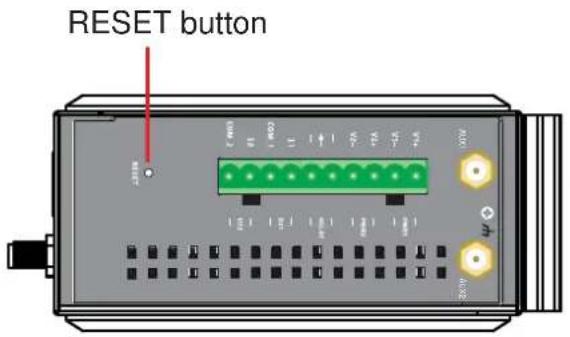
The RESET button is located on the top panel of the AWK-5222. You can reboot the AWK-5222 or reset it to factory default settings by pressing the RESET button with a pointed object such as an unfolded paper clip.
- System reboot: Hold the RESET button down for under 5 seconds and then release.
- Reset to factory default: Hold the RESET button down for over 5 seconds until the STATE LED starts blinking green. Release the button to reset the AWK-5222.
Relay (Digital Output)
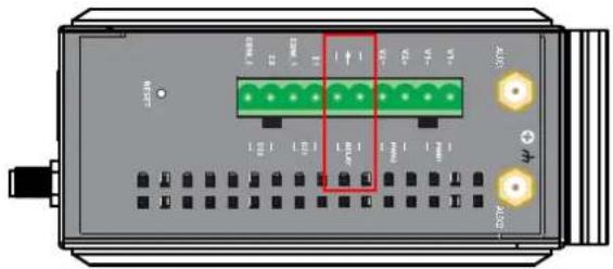
The AWK-5222 has one relay output, which consists of the 2 terminal block contacts on the top panel, as shown below. These relay contacts are used to forward system failure and user-configured events.
The two wires attached to the relay contacts form an open circuit when a user-configured event is triggered. If a user-configured event does not occur, the relay circuit will remain closed. For safety reason, the relay circuit is kept open when the AWK-5222 is not powered.
The AWK-5222's relay status is summarized as follows:
| Power Status Event Relay | ||
| Off | --- | Open |
| Yes | Open | |
| No | Short | |
On
Antenna
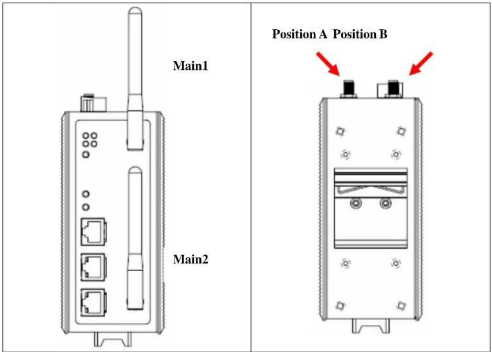
If you need to improve the performance of the Main1 and Main2 antennas, you can connect additional antennas to the side panel of the AWK-5222 using an antenna cable (Position A: AUX1 and Position B: AUX2). The default antenna for the AWK-5222 is a 2 dBi, dual-band omni-directional antenna, RP-SMA (male).
This chapter explains how to install Moxa's AirWorks AWK-5222 for the first time, and quickly set up your wireless network and test whether the connection is running well. With the function guide, you can find out the functions you need easily.
In this chapter, we cover the following topics:
☐ First-time Installation and Configuration
□ Communication Testing
□ Function Guiding Map
First-time Installation and Configuration
Before installing the AWK-5222, make sure that all items in the Package Checklist are in the box. In addition, you will need access to a notebook computer or PC equipped with an Ethernet port. The AWK-5222 has a default IP address that you must use when connecting to the device for the first time.
Step 1: Select the power source.
The AWK-5222 can be powered by DC power input or PoE (Power over Ethernet). The AWK-5222 will use whichever power source you choose.
NOTE: The ITE unit is to be connected only to PoE networks without routing to the outside plant.
Step 2: Connect the AWK-5222 to a notebook or PC.
Since the AWK-5222 supports MDI/MDI-X auto-sensing, you can use either a straight-through cable or crossover cable to connect the AWK-5222 to a computer. If the LED indicator on AWK-5222's LAN port lights up, it means the connection is established.
Step 3: Set up the computer's IP address.
Set an IP address on the same subnet as the AWK-5222. Since the AWK-5222's default IP address is 192.168.127.253, and the subnet mask is 255.255.255.0, you should set the IP address of the computer to 192.168.127.xxx.

NOTE
After you select Maintenance Load Factory Default and click the Submit button, the AWK-5222 will be reset to factory default settings and the IP address will be also reset to 192.168.127.253.
Step 4: Use the web-based manager to configure AWK-5222
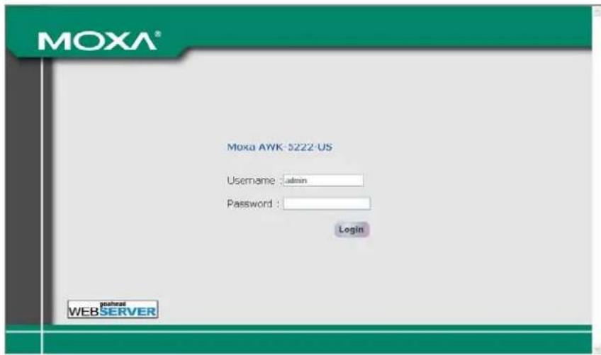
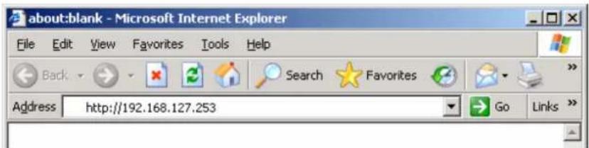
Open your computer's web browser and type http://192.168.127.253 in the address field to access the homepage of the web-based Network Manager. Before the homepage opens, you will need to enter the user name and password as shown in the following figure. For first-time configuration, enter the default user name and password and then click on the Login button:

NOTE
Default user name and password:
User Name: admin
Password: root
For security reasons, we strongly recommend changing the default password. To do so, select Maintenance > Password, and then follow the on-screen instructions to change the password.

NOTE
After you click Submit to apply changes, you can see that the web page is refreshed, and the string “(Update)” and a blinking reminder will be shown on the upper-right corner of web page, as follow.

To make the changes effective, click Restart and then Save and Restart after you change the settings. About 30 seconds are needed for the AWK-5222 to complete its restart process.
Step 5: Select the operation mode for the AWK-5222.
By default, the AWK-5222's operation mode is set to Wireless redundancy. You can change the setting in Wireless Settings → Operation mode if you would like to use the Wireless bridge or AP-Client mode instead. Detailed information about configuring the AWK-5222's operation can be found in Chapter 3.
Step 6: Test communications.
We will describe 2 test methods to make sure the network connection has been established. Please refer to the following section for more details.
Communication Testing
After installation, you can run a sample test to make sure the AWK-5222 and wireless connection are functioning normally. Two testing methods are explained in the following sections. Use the first method if you are using only one AWK-5222 device, and use the second method if you are using two or more AWK-5222s.
Testing Method for one AWK-5222
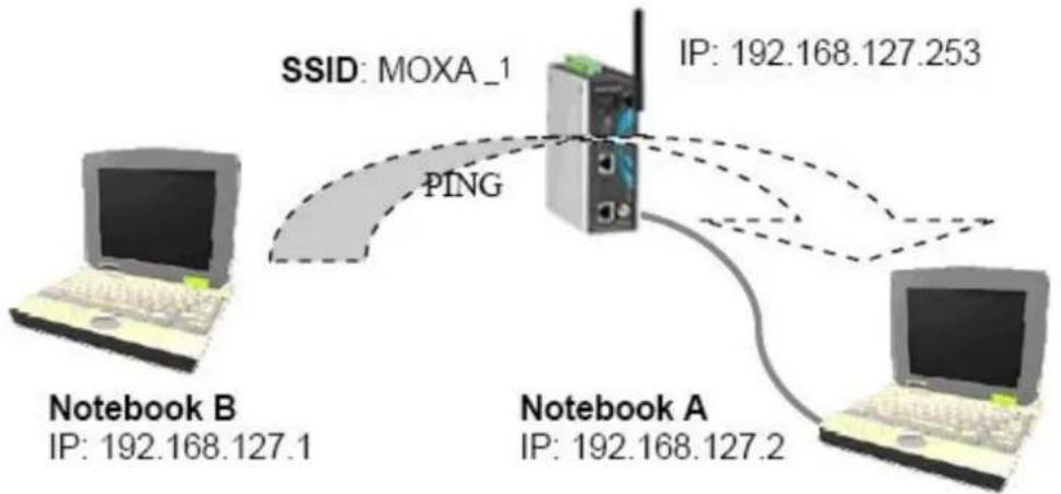
If you are only using one AWK-5222, you will need a second notebook computer equipped with a WLAN card. Configure the WLAN card to connect to the AWK-5222 (NOTE: the default SSID is MOXA_1), and change the IP address of the second notebook (B) so that it is on the same subnet as the first notebook (A), which is connected to the AWK-5222.
After configuring the WLAN card, establish a wireless connection with the AWK-5222 and open a DOS window on Notebook B. At the prompt, type
ping
and then press Enter (see the figure below). A “Reply from IP address …” response means the communication was successful. A “Request timed out.” response means the communication failed. In this case, recheck the configuration to make sure the connections are correct.
flowchart
graph TD
    A["Notebook B\nIP: 192.168.127.1"] -->|PING| B["Device"]
    C["Notebook A\nIP: 192.168.127.2"] -->|IP: 192.168.127.253| B
    B --> D["Server"]
    style A fill:#f9f,stroke:#333
    style C fill:#f9f,stroke:#333
    style B fill:#ccf,stroke:#333
    style D fill:#cff,stroke:#333
Testing Method for two or more AWK-5222s
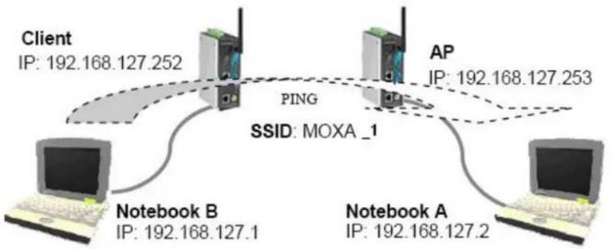
If you have two or more AWK-5222s, you will need a second notebook computer (B) equipped with an Ethernet port. Use the default settings for the first AWK-5222 connected to notebook A and change the second or third AWK-5222 connected to notebook B to Client mode. Then, configure the notebooks and AWK-5222s properly.
flowchart
graph TD
    Client["Client\nIP: 192.168.127.252"] -->|PING| AP["AP\nIP: 192.168.127.253"]
    AP -->|SSID: MOXA_1| NotebookA["Notebook A\nIP: 192.168.127.2"]
    NotebookA -->|IP| NotebookB["Notebook B\nIP: 192.168.127.1"]
    NotebookB -->|IP| Client
After setting up the testing environment, open a DOS window on notebook B. At the prompt, type
ping
and then press Enter. A "Reply from IP address ..." response means the communication was successful. A "Request timed out" response means the communication failed. In this case, recheck the configuration to make sure the connections are correct.
Function Guiding Map
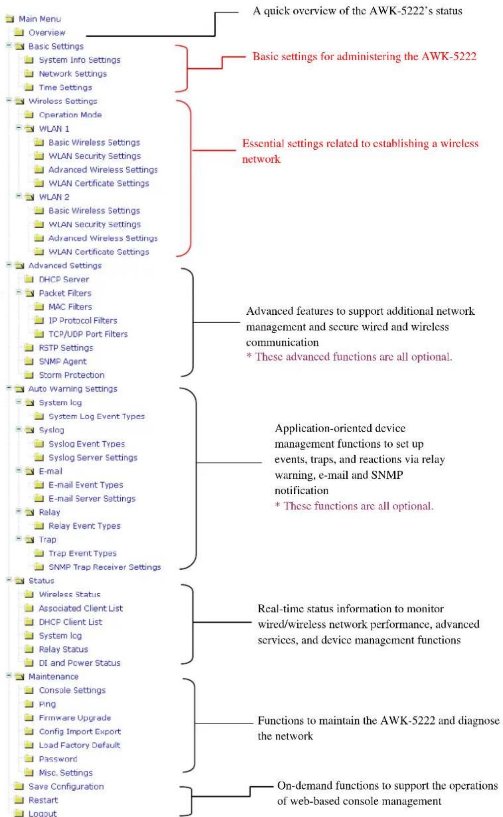
The management functions are categorized in a tree and shown in the left field of the web-based management console. You can efficiently locate the function you need with the following guiding map.
flowchart
graph TD
    A["Main Menu"] --> B["A quick overview of the AWK-5222's status"]
    A --> C["Basic Settings for administering the AWK-5222"]
    A --> D["Essential settings related to establishing a wireless network"]
    A --> E["Advanced Features to support additional network management and secure wired and wireless communication"]
    E --> F["* These advanced functions are all optional."]
    E --> G["Application-oriented device management functions to set up events, traps, and reactions via relay warning, e-mail and SNMP notification"]
    E --> H["Real-time status information to monitor wired/wireless network performance, advanced services, and device management functions"]
    A --> I["Main Menu Overview"]
    A --> J["Basic Settings"]
    A --> K["Wireless Settings"]
    A --> L["Advanced Settings"]
    A --> M["Auto Warning Settings"]
    A --> N["Status"]
    A --> O["Maintenance"]
    A --> P["Logout"]

    subgraph Section 1
        A1["Overview"]
        A2["Basic Settings"]
        A3["Network Settings"]
        A4["Time Settings"]
        A5["WLAN 1"]
        A6["WLAN Security Settings"]
        A7["WLAN Security Settings"]
        A8["WLAN Security Settings"]
        A9["WLAN Security Settings"]
        A10["WLAN Security Settings"]
        A11["WLAN Security Settings"]
        A12["WLAN Security Settings"]
        A13["WLAN Security Settings"]
        A14["WLAN Security Settings"]
        A15["WLAN Security Settings"]
        A16["WLAN Security Settings"]
        A17["WLAN Security Settings"]
        A18["WLAN Security Settings"]
        A19["WLAN Security Settings"]
        A20["WLAN Security Settings"]
        A21["WLAN Security Settings"]
        A22["WLAN Security Settings"]
        A23["WLAN Security Settings"]
        A24["WLAN Security Settings"]
        A25["WLAN Security Settings"]
        A26["WLAN Security Settings"]
        A27["WLAN Security Settings"]
        A28["WLAN Security Settings"]
        A29["WLAN Security Settings"]
        A30["WLAN Security Settings"]
        A31["WLAN Security Settings"]
        A32["WLAN Security Settings"]
        A33["WLAN Security Settings"]
        A34["WLAN Security Settings"]
        A35["WLAN Security Settings"]
        A36["WLAN Security Settings"]
        A37["WLAN Security Settings"]
        A38["WLAN Security Settings"]
        A39["WLAN Security Settings"]
        A40["WLAN Security Settings"]
        A41["WLAN Security Settings"]
        A42["WLAN Security Settings"]
        A43["WLAN Security Settings"]
        A44["WLAN Security Settings"]
        A45["WLAN Security Settings"]
        A46["WLAN Security Settings"]
        A47["WLAN Security Settings"]
        A48["WLAN Security Settings"]
        A49["WLAN Security Settings"]
        A50["WLAN Security Settings"]
        A51["WLAN Security Settings"]
        A52["WLAN Security Settings"]
        A53["WLAN Security Settings"]
        A54["WLAN Security Settings"]
        A55["WLAN Security Settings"]
        A56["WLAN Security Settings"]
        A57["WLAN Security Settings"]
        A58["WLAN Security Settings"]
        A59["WLAN Security Settings"]
        A60["WLAN Security Settings"]
        A61["WLAN Security Settings"]
        A62["WLAN Security Settings"]
        A63["WLAN Security Settings"]
        A64["WLAN Security Settings"]
        A65["WLAN Security Settings"]
        A66["WLAN Security Settings"]
        A67["WLAN Security Settings"]
        A68["WLAN Security Settings"]
        A69["WLAN Security Settings"]
        A70["WLAN Security Settings"]
        A71["WLAN Security Settings"]
        A72["WLAN Security Settings"]
        A73["WLAN Security Settings"]
        A74["WLAN Security Settings"]
        A75["WLAN Security Settings"]
        A76["WLAN Security Settings"]
        A77["WLAN Security Settings"]
        A78["WLAN Security Settings"]
        A79["WLAN Security Settings"]
        A80["WLAN Security Settings"]
        A81["WLAN Security Settings"]
        A82["WLAN Security Settings"]
        A83["WLAN Security Settings"]
        A84["WLAN Security Settings"]
        A85["WLAN Security Settings"]
        A86["WLAN Security Settings"]
        A87["WLAN Security Settings"]
        A88["WLAN Security Settings"]
        A89["WLAN Security Settings"]
        A90["WLAN Security Settings"]
    end

    subgraph Section 2
        B1["Basic Settings for administering the AWK-5222"]
        B2["Essential settings related to establishing a wireless network"]
    end

    subgraph Section 3
        C1["Advanced Settings"]
        C2["Advanced features to support additional network management and secure wired and wireless communication * These advanced functions are all optional."]
    end

    subgraph Section 4
        D1["Auto Warning Settings"]
        D2["Status: Wireless Status, Associated Client List, DHCP Client List, System log, Relay Status, DI and Power Status, Maintenance, Console Settings, Ping, Firmware Upgrade, Config Import Export, Load Factory Default, Password, Misc. Settings, Save Configuration, Restart, Logout"]

    end

    subgraph Section 5
        E1["Application-oriented device management functions to set up events, traps, and reactions via relay warning, e-mail and SNMP notification * These functions are all optional."]
    end

    subgraph Section 6
        F1["Real-time status information to monitor wired/wireless network performance, advanced services, and device management functions"]
    end

    subgraph Section 7
        G1["Functions to maintain the AWK-5222 and diagnose the network"]
    end

    subgraph Section 8
        H1["On-demand functions to support the operations of web-based console management"]
    end
In this chapter, we will explain each web management page of the web-based console configuration. Moxa's easy-to-use management functions will help you set up your AWK-5222, as well as establish and maintain your wireless network easily.
In this chapter, we cover the following topics:
☐ Configuration by Web Browser
Overview
Basic Settings
□ Wireless Settings
□ Advanced Settings
□ Auto Warning Setting
Status
□ Maintenance
□ Save Configuration
□ Restart
□ Logout
Configuration by Web Browser
Moxa AWK-5222's web browser interface provides a convenient way to modify its configuration and access the built-in monitoring and network administration functions. The recommended web browser is Microsoft® Internet Explorer 5.5 or 6.0 with JVM (Java Virtual Machine) installed.

NOTE
To use the AWK-5222's management and monitoring functions from a PC host connected to the same LAN as the AWK-5222, you must make sure that the PC host and AWK-5222 are on the same logical subnet. Similarly, if the AWK-5222 is configured for other VLAN settings, you must make sure your PC host is on the management VLAN.
The Moxa AWK-5222's default IP is 192.168.127.253.
Follow the steps below to access the AWK-5222's web-based console management.
- Open your web browser (ex. Internet Explorer) and type the AWK-5222's IP address in the address field. Then press Enter to establish the connection.
- The Web Console Login page will open. Enter the password (User Name is set as admin; the default password is root if a new password has not been set.) and then click Login to continue.
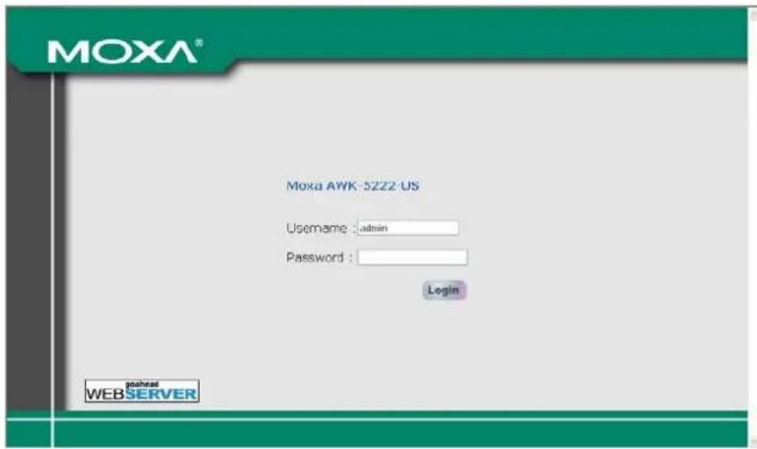
You may need to wait a few moments for the web page download onto your computer. Please note that the Model name and IP address of your AWK-5222 are both shown on the title of the web page. This information can help you identify multiple AWK-5222s.
You can use the menu tree on the left side of the window to open the function pages to access each of AWK-5222's functions.
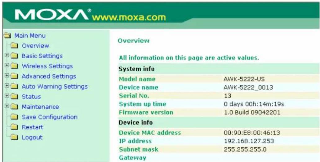
In the following paragraphs, we will go through each of the AWK-5222's management functions in detail. You can also get a quick overview of these functions in the "Function Guiding Map" section of Chapter 2.

NOTE
The model name of the AWK-5222 is shown as AWK-5222-XX where XX indicates the country code. The country code represents the AWK-5222 version and which bandwidth it uses. We use AWK-5222-US as an example in the following figures. The country code of model name on the screen may vary if you are using a different version (band) AWK-5222.

NOTE
For security reasons, you will need to log back into the AWK-5222 after the 5-minute time-out.
Overview
The Overview page summarizes the AWK-5222's current status. The information is categorized into several groups: System info, Device info and 802.11 info.
Overview
All information on this page are active values.
System info
| Model name | AWK-5222-US |
| Device name | AWK-5222_0001 |
| Serial No. | 1 |
| System up time | 0 days 00h:02m:30s |
| Firmware version | 1.0 Build 09060100 |
Device info
| Device MAC address | 00:90:E8:00:40:01 |
| IP address | 192.168.127.253 |
| Subnet mask | 255.255.255.0 |
| Gateway |
802.11 info
| Country code | US | |
| Operation mode | Wireless redundancy - Redundant AP (WLAN 1) | Wireless redundancy - Redundant AP (WLAN 2) |
| Channel | 6 | 11 |
| RF type | B/G Mixed | B/G Mixed |
| SSID | MOXA_1 | MOXA_2 |
Basic Settings
The Basic Settings group includes the most commonly used settings required by administrators to maintain and control the AWK-5222.
System Info Settings
The System Info items, especially Device name and Device description, are displayed and included on the Overview page, SNMP information, and alarm emails. Setting System Info items makes it easier to identify the different AWK-5222s connected to your network.
System Info Settings
| Device name | AP_011 |
| Device location | Area 32, 5th Floor |
| Device description | No. 11 of ABC supporting system |
| Device contact information | John Davis, sysop@abc.com |
Device name
| Setting Description Factory Default | ||
| Max. 31 Characters This | option is useful for specifying the role or application of different AWK-5222 units. | AWK-5222_ |
Device location
| Setting Description Factory Default | ||
| Max. 31 Characters To specify the location of different AWK-5222 units. | None | |
Device description
| Setting Description Factory Default | ||
| Max. 31 Characters Use | this space to record more detailed description of AWK-5222 | None |
Device name
| Setting Description Factory Default | ||
| Max. 31 Characters To provide information about whom to contact in order to resolve problems. Use this space to record contact information of the person responsible for maintaining this AWK-5222. | None | |
Network Settings
The Network Settings configuration allows you to modify the usual TCP/IP network parameters. An explanation of each configuration item is given below.
Network Settings
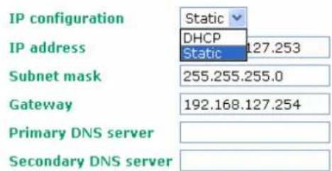
IP configuration
| Setting Description Factory Default | ||
| DHCP The AWK-5222's IP address will be assigned automatically by the network's DHCP server | Static | |
| Static Set up the AWK-5222's IP address manually. | ||
IP address
| Setting Description Factory Default | ||
| AWK-5222's IP address | Identifies the AWK-5222 on a TCP/IP network. | 192.168.127.253 |
Subnet mask
| Setting Description Factory Default | ||
| AWK-5222's subnet mask | Identifies the type of network to which the AWK-5222 is connected (e.g., 255.255.0.0 for a Class B network, or 255.255.255.0 for a Class C network). | 255.255.255.0 |
Gateway
| Setting Description Factory Default | ||
| AWK-5222's default gateway | The IP address of the router that connects the LAN to an outside network. | None |
Primary/ Secondary DNS server
| Setting Description Factory Default | ||
| IP address of Primary/Secondary DNS server | The IP address of the DNS Server used by your network. After entering the DNS Server's IP address, you can input the AWK-5222's URL (e.g., http://ap11.abc.com) in your browser's address field instead of entering the IP address. The Secondary DNS server will be used if the Primary DNS server fails to connect. | None |
Time Settings
The AWK-5222 has a time calibration function based on information from an NTP server or user specified Date and Time information. Functions such as Auto warning can add real-time information to the message.
Time Settings

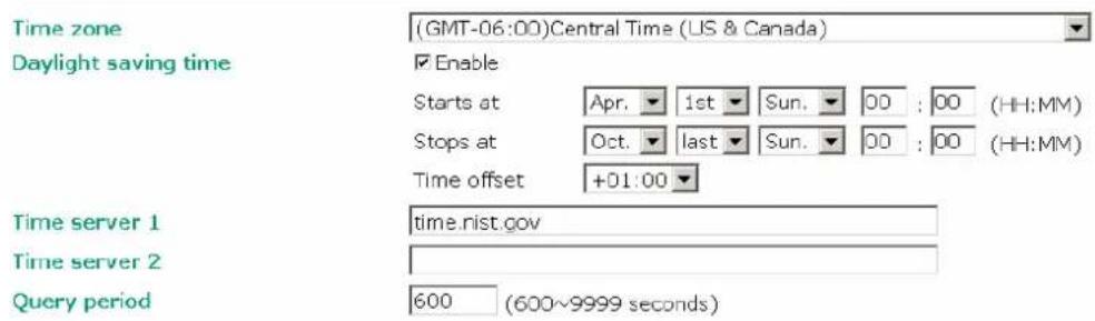
Current local time shows the AWK-5222's system time when you open this web page. You can click on the Set Time button to activate the update after setting up the date and time parameters. An “(Updated)” string will appear to indicate that the change is complete. Local time settings will be immediately activated in the system without running Save and Restart.

NOTE
The AWK-5222 has a real time clock (RTC). Users are strongly recommended to update the Local time for the AWK-5222 after initial setup or long-term shutdown, especially when the network does not have an Internet connection for accessing the NTP server or there is no NTP server on the LAN.
Current local time
| Setting Description Factory Default | ||
| User adjustable time The | date and time parameters allow configuration of the local time with immediate activation. | None (yyyy/mm/dd hh:mm:ss format; 24-hour format.) |
Time zone
| Setting Description Factory Default | ||
| User selectable time zone | The time zone setting allows conversion from GMT (Greenwich Mean Time) to local time. | GMT (Greenwich Mean Time) |

ATTENTION
Changing the time zone will automatically adjust the Current local time. You should configure the Time zone before setting the Current local time.
Daylight saving time
| Setting Description Factory Default | ||
| Enable/ Disable Daylight | saving time (also know as DST or summer time) involves advancing clocks (usually 1 hour) during the summer time to provide an extra hour of daylight in the afternoon. | Disable |
When Daylight saving time is enabled, the following parameters can be shown:
- The Starts at parameter allows users to enter the date that daylight saving time begins.
- The Stops at parameter allows users to enter the date that daylight saving time ends.
- The Time offset parameter indicates how many hours forward the clock should be advanced.
Time server 1/2
| Setting Description Factory Default | ||
| The 1st/ 2nd time server IP/Name | IP or Domain address of NTP time server. The 2nd time will be used if the 1st NTP server fails to connect. | None |
Query period
| Setting Description Factory Default | ||
| Query period time(1- 9999 seconds) | This parameter determines how often the time is updated from the NTP server. | 600 (seconds) |
Wireless Settings
The essential settings for wireless networks are presented in this function group. Settings must be properly set before establishing your wireless network.
Operation Mode
The AWK-5222 supports three operation modes that are used for different wireless network applications:
Wireless Redundancy
In traditional architectures, most vendors only provide a single RF AP and Client, in which the AP connects one or more Clients to the network. Since the AP and Client are connected by a single RF connection, if the RF connection is disconnected the system or network behind the Client will be disconnected, too.
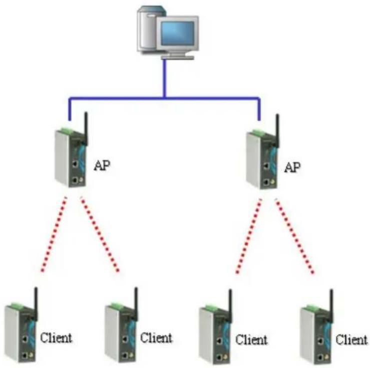
flowchart
graph TD
    A["Computer"] --> B["AP"]
    A --> C["AP"]
    B --> D["Client"]
    B --> E["Client"]
    C --> F["Client"]
    C --> G["Client"]
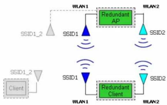
With the new wireless redundancy technology, you can set up a redundant wireless connection between a redundant client device and a redundant AP device. The redundant structure involves using the AWK-5222's two RF modules to set up two independent wireless connections between the redundant client and redundant AP devices. If either of the two wireless connections fails, the other wireless connection will continue transmitting packets between the redundant client and redundant AP devices. In addition to carrying one or more redundant clients, standard single RF clients can also associate with the redundant AP. One of the biggest advantages of the AWK-5222's wireless redundancy mode is that you can expect "zero data loss."
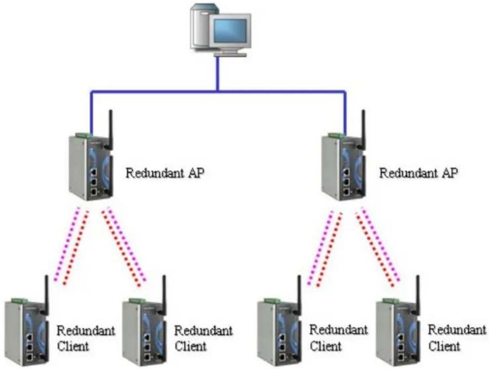
flowchart
graph TD
    A["Computer"] --> B["Redundant AP"]
    A --> C["Redundant AP"]
    B --> D["Redundant Client"]
    B --> E["Redundant Client"]
    C --> F["Redundant Client"]
    C --> G["Redundant Client"]
    D -.-> H["Redundant Client"]
    E -.-> I["Redundant Client"]
    F -.-> J["Redundant Client"]
    G -.-> K["Redundant Client"]
The following figure shows the Wireless Redundancy operation mode:
Operation mode
WLAN Operation mode
Wireless redundancy
Redundant AP

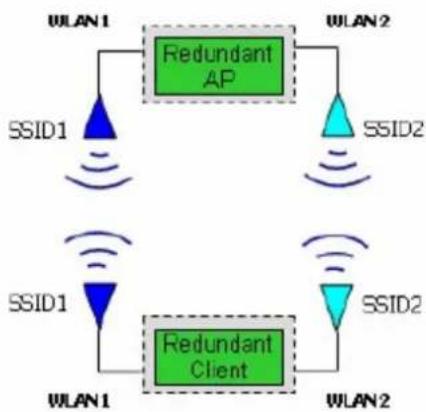
flowchart
graph TD
    A["WLAN 1"] --> B["Redundant AP"]
    B --> C["WLAN 2"]
    D["SSID1"] --> E["Redundant Client"]
    E --> F["SSID2"]
    G["SSID1"] --> H["Redundant Client"]
    H --> I["SSID2"]
    J["WLAN 1"] --> K["Redundant Client"]
    K --> L["WLAN 2"]
    M["SSID1"] --> N["Redundant Client"]
    N --> O["WLAN 2"]
△WLANs with same color must have identical RF type, SSID, and security settings.
WLAN Operation mode
| Setting Description Factory Default | ||
| Redundant AP AP with Dual RF redundancy capable of serving dual RF clients. | Redundant AP | |
| Redundant Client Dual RF redundant clients can join dual RF redundant APs. | ||
Wireless Bridge
A bridge is a network component that connects two networks. AWK-5222's bridge operation is based on the AP (master) and Client (Slave) concept. Both sides of the connection must have the same RF type, SSID, and security settings.
For single RF mesh networks, we can use WDS to establish a static bridge link. In this case, the APs at both ends of the WDS link must be configured manually with each other's MAC addresses. The performance of a single RF bridge will be poor if more nodes are added.
The AWK-5222's dual RF bridge concept is different from using a single RF, because the AWK-5222 has dual RFs, and offer users a cascade link to bridge the two ends without narrowing down the throughput.

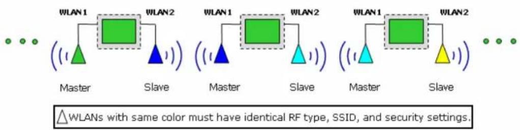
flowchart
graph TD
    subgraph Master
        A1["Green Triangle"] --> B1["Green Square"]
        B1 --> C1["Blue Triangle"]
    end
    subgraph Slave
        D1["Blue Triangle"] --> E1["Blue Triangle"]
        E1 --> F1["Blue Triangle"]
    end
    G1["Green Square"] --> H1["Green Square"]
        H1 --> I1["Blue Triangle"]
    end
    subgraph Master
        J1["Green Square"] --> K1["Green Square"]
        K1 --> L1["Blue Triangle"]
        L1 --> M1["Blue Triangle"]
    end
    subgraph Slave
        N1["Green Square"] --> O1["Green Square"]
        O1 --> P1["Blue Triangle"]
        P1 --> Q1["Blue Triangle"]
    end
    W1["WLAN 1"] --> X1["Master"]
    X1 --> Y1["Slave"]
    Y1 --> Z1["Slave"]
    Z1 --> AA["Slave"]
    AA --> AB["Slave"]
    AB --> AC["Slave"]
    AC --> AD["Slave"]
    AD --> AE["Slave"]
    AE --> AF["Slave"]
    AF --> AG["Slave"]
    AG --> AH["Slave"]
    AH --> AI["Slave"]
    AI --> AJ["Slave"]
    AJ --> AK["Slave"]
    AK --> AL["Slave"]
    AL --> AM["Slave"]
    AM --> AN["Slave"]
    AN --> AO["Slave"]
    AO --> AP["Slave"]
    AP --> AQ["Slave"]
    AQ --> AR["Slave"]
    AR --> AS["Slave"]
    AS --> AT["Slave"]
    AT --> AU["Slave"]
    AU --> AV["Slave"]
    AV --> AW["Slave"]
    AW --> AX["Slave"]
    AX --> AY["Slave"]
    AY --> AZ["Slave"]
    AZ --> BA["Slave"]
    BA --> BB["Slave"]
    BB --> BC["Slave"]
    BC --> BD["Slave"]
    BD --> BE["Slave"]
    BE --> BF["Slave"]
    BF --> BG["Slave"]
    BG --> BH["Slave"]
    BH --> BI["Slave"]
    BI --> BJ["Slave"]
    BJ --> BK["Slave"]
    BK --> BL["Slave"]
    BL --> BM["Slave"]
    BM --> BN["Slave"]
    BN --> BO["Slave"]
    BO --> BP["Slave"]
    BP --> BQ["Slave"]
    BQ --> BR["Slave"]
    BR --> BS["Slave"]
WLAN 1/WLAN 2 Operation mode
| Setting Description Factory Default | ||
| Master Master can build | a connection with a Slave that has the same RF type, SSID, and security settings. | AP for WLAN 1Master for WLAN 2 |
| Slave Slave can build a | connection with a master that has the same RF type, SSID, and security settings. | |
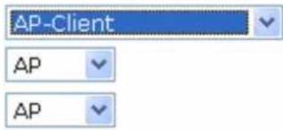
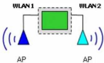
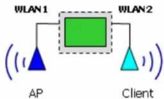
AP-Client
AP-Client mode provides a more flexible topology to allow the user to configure the 2 RF module for an AP or Client.
Operation mode
WLAN 1 Operation mode
WLAN 2 Operation mode
flowchart
graph TD
    A["WLAN 1"] --> B["AP"]
    C["WLAN 2"] --> D["AP"]
    B --> E["Green Block"]
    D --> E
    style E fill:#90EE90,stroke:#333,stroke-width:2px
OR
flowchart
graph TD
    A["AP"] --> B["WLAN1"]
    C["Client"] --> D["WLAN2"]
    B --> E["Green Block"]
    D --> E
    style A fill:#00FF00,stroke:#333
    style C fill:#00FF00,stroke:#333
    style B fill:#FFFF00,stroke:#333
    style D fill:#FFFF00,stroke:#333
Matching Table for AP-Client's WLANs:
| WLAN 1 WLAN 2 Allowable Settin | g | |
| AP | AP | Allow |
| AP | Client | Allow |
| Client | Client | Not Allow |
| Client | AP | Allow |
WLAN1/WLAN2
Some applications already have existing Clients in the environment. The AWK-5222 not only can carry dual RF clients, but also single RF or existing Clients to the Ethernet LAN. This function is available in Wireless Redundancy mode's Redundant AP, or Wireless Bridge mode's Master page. Descriptions of other operation modes can be found in the "Basic Wireless Settings" section.
Enabling Non-Redundant (Single RF) AP
Wireless Redundancy mode's Redundant AP
This AP functionality can be set to Enable or Disable on the basic wireless settings page. If AP functionality is set to Enable, the Status will appear as Active, which means that the WLAN is ready to operate in the operation mode you are setting. For AP functionality settings, click on Edit for the AP operation mode, as described on the following page.
| Status | SSID | Operation Mode | Action |
| Active | MOXA_1 | Redundant AP | Edit |
| Disabled | MOXA_1_1 | AP | Edit |
flowchart
graph TD
    A["Client"] -->|SSID1_2| B["Redundant AP"]
    B -->|SSID1| C["Redundant Client"]
    C -->|SSID1| D["Redundant Client"]
    D -->|SSID1| E["Redundant AP"]
    E -->|SSID2| F["Redundant Client"]
    F -->|SSID2| G["Redundant AP"]
    G -->|SSID2| H["Redundant Client"]
    H -->|SSID2| I["Redundant AP"]
    I -->|SSID1| J["Redundant AP"]
    J -->|SSID1| K["Redundant Client"]
    K -->|SSID1| L["Redundant AP"]
    L -->|SSID1| M["Redundant Client"]
    M -->|SSID1| N["Redundant AP"]
    N -->|SSID1| O["Redundant Client"]
    O -->|SSID1| P["Redundant AP"]
    P -->|SSID1| Q["Redundant Client"]
    Q -->|SSID1| R["Redundant AP"]
    R -->|SSID1| S["Redundant Client"]
    S -->|SSID1| T["Redundant AP"]
    T -->|SSID1| U["Redundant Client"]
    U -->|SSID1| V["Redundant AP"]
    V -->|SSID1| W["Redundant Client"]
    W -->|SSID1| X["Redundant AP"]
    X -->|SSID1| Y["Redundant Client"]
    Y -->|SSID1| Z["Redundant AP"]
    Z -->|SSID1| AA["Redundant Client"]
    AA -->|SSID1| AB["Redundant AP"]
    AB -->|SSID1| AC["Redundant Client"]
    AC -->|SSID1| AD["Redundant AP"]
    AD -->|SSID1| AE["Redundant Client"]
    AE -->|SSID1| AF["Redundant AP"]
    AF -->|SSID1| AG["Redundant Client"]
    AG -->|SSID1| AH["Redundant AP"]
    AH -->|SSID1| AI["Redundant Client"]
    AI -->|SSID1| AJ["Redundant AP"]
    AJ -->|SSID1| AK["Redundant Client"]
    AK -->|SSID1| AL["Redundant AP"]
    AL -->|SSID1| AM["Redundant Client"]
    AM -->|SSID1| AN["Redundant AP"]
    AN -->|SSID1| AO["Redundant Client"]
    AO -->|SSID1| AP["Redundant AP"]
    AP -->|SSID1| AQ["Redundant Client"]
    AQ -->|SSID1| AR["Redundant AP"]
    AR -->|SSID1| AS["Redundant Client"]
    AS -->|SSID1| AT["Redundant AP"]
    AT -->|SSID1| AU["Redundant Client"]
    AU -->|SSID1| AV["Redundant AP"]
    AV -->|SSID1| AW["Redundant Client"]
    AW -->|SSID1| AX["Redundant AP"]
    AX -->|SSID1| AY["Redundant Client"]
    AY -->|SSID1| AZ["Redundant AP"]
    AZ -->|SSID1| BA["Redundant Client"]
    BA -->|SSID1| BB["Redundant AP"]
    BB -->|SSID1| BC["Redundant Client"]
    BC -->|SSID1| BD["Redundant AP"]
    BD -->|SSID1| BE["Redundant Client"]
    BE -->|SSID1| BF["Redundant AP"]
    BF -->|SSID1| BG["Redundant Client"]
    BG -->|SSID1| BH["Redundant AP"]
    BH -->|SSID1| BI["Redundant Client"]
    BI -->|SSID1| BJ["Redundant AP"]
    BJ -->|SSID1| BK["Redundant Client"]
    BK -->|SSID1| BL["Redundant AP"]
    BL -->|SSID1| BM["Redundant Client"]
    BM -->|SSID1| BN["Redundant AP"]
    BN -->|SSID1| BO["Redundant Client"]
    BO -->|SSID1| BP["Redundant AP"]
    BP -->|SSID1| BQ["Redundant Client"]
    BQ -->|SSID1| BR["Redundant AP"]
    BR -->|SSID1| BS["Redundant Client"]
    BS -->|SSID1| BT["Redundant AP"]
    BT -->|SSID1| BU["Redundant Client"]
    BU -->|SSID1| BV["Redundant AP"]
    BV -->|SSID1| BW["Redundant Client"]
△WLANs with same color must have identical RF type, SSID, and security settings.
After Edit is selected, you can select Enable or Disable in AP functionality.
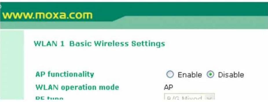
AP functionality
| Setting Description Factory Default | |||
| Disable | Redundant non-redundant Clients. | AP cannot | Disable server |
| Enable | Redundant non-redundant Clients. | AP can | |
Wireless Bridge Mode's Master
You are allowed to edit this AP functionality to Enable or Disable on the basic wireless settings page. If AP functionality is set to Enable, the Status will appear as Active, which means that the WLAN is ready to operate in the operation mode you are setting. For AP functionality settings, click on Edit, as described below.
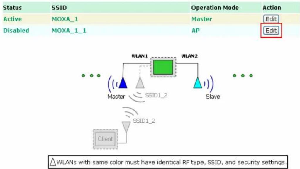
After Edit is selected, you can select Enable or Disable in AP functionality.
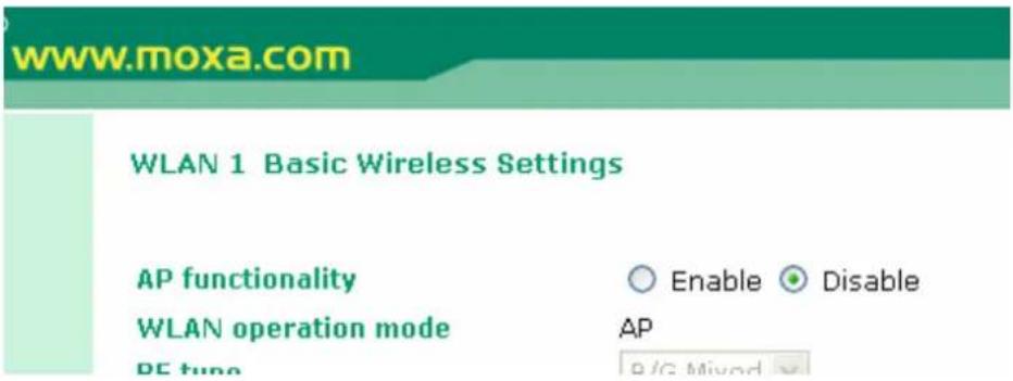
AP functionality
| Setting Description Factory Default | ||
| Disable Master can only serve a single slave. | Disable | |
| Enable Master can serve single RF clients. | ||
Basic Wireless Setting
The following figure shows the Basic Wireless Settings page. The parameters and options are described as follows:

NOTE
Please note that WLAN 1's RF type supports 802.11b/g mode only; 802.11a mode is not available. WLAN 2's RF type does support 802.11a/b/g.
WLAN operation mode
RF type
Channel
SSID
SSID broadcast
AP
B/G Mixed


MOXA_2

Enable

Disable
Submit
RF type
| Setting Description Factory Default | ||
| A Supports IEEE802.11a standard only | B/G Mixed | |
| B Supports IEEE802.11b standard only | ||
| G Supports IEEE802.11g standard only | ||
| B/G Mixed Supports both IEEE 802.11b/g standards, but 802.11g's throughput may suffer when 802.11b clients are on the network | ||
Channel (for Redundant AP, AP, or Master mode only)
| Setting Description Factory Default | ||
| Available channels vary with RF type | AWK-5222 plays a role of wireless AP. | 6 (in B/G Mixed mode) |
SSID
| Setting Description Factory Default | ||
| Max. 31 Characters | The SSID of a client and the SSID of the AP must be identical for them to communicate with each other. | MOXA_1 for WLAN1, MOXA_2 for WLAN2 |
SSID broadcast (for Redundant AP, AP, or Master mode only)
| Setting Description Factory Default | |
| Enable/ Disable SSID can be broadcast or not. Enable |

NOTE
If your device uses redundant Client, Client, or Slave mode, you can find an additional Site Survey button on basic wireless settings page. The button supports site survey and pops up a dialog box listing the information for available APs, as shown in the following figure. You can click on the SSID of an entity and bring the value of its SSID onto the SSID field of the Basic Wireless Settings page. Clicking on the Refresh button will re-scan and update the table.

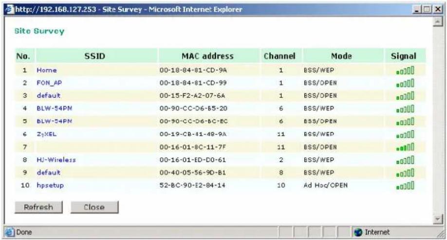
WLAN Security Settings
The following figure shows the WLAN1/2 Security Settings page. The parameters and options are described as follows:

NOTE
When you switch to Wireless Redundancy mode, you will see an additional WLAN Security Setting overview page. Please click on Edit to modify WLAN security settings.
WLAN 1 Security Setting Selection
| Status | SSID | Operation Mode | Security Mode | Action |
| Active | MOXA_1 | Redundant - AP | OPEN | Edit |
| Disabled | MOXA_1_1 | AP | OPEN | Edit |
The AWK-5222 provides four standardized wireless security modes: Open, WEP (Wired Equivalent Privacy), WPA (Wi-Fi Protected Access) and WPA2. Several types of security models are available in AWK-5222 by selecting Security mode and WPA type:
- Open: No authentication, no data encryption.
- WEP: Static WEP (Wired Equivalent Privacy) keys must be manually configured.
- WPA/WPA2-Personal: also known as WPA/WPA2-PSK. You need to specify the Pre-Shared Key in the Passphrase field, which will be used by the TKIP or AES engine as a master key to generate keys that actually encrypt outgoing packets and decrypt incoming packets.
- WPA/WPA2-Enterprise: also called WPA/WPA2-EAP (Extensible Authentication Protocol). In addition to device-based authentication, WPA/WPA2-Enterprise enables user-based authentication via IEEE802.1X. The AWK-5222 can support three EAP methods: EAP-TLS, EAP-TTLS, and EAP-PEAP.
SSID
Security mode
MOXA_1
Open
Submit
Security mode
| Setting Description Factory Default | |||
| Open | No authentication | Open is | |
| WEP | Static | WEP | |
| WPA WPA is used | |||
| WPA2 Fully supports IEEE802.11i with “TKIP/AES + 802.1X” | |||
used
Open
For security reasons, it is highly recommended that the security mode should be set to the options other than Open System. When the security mode is set to Open System, no authentication or data encryption will be performed.
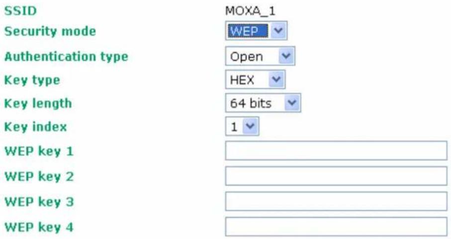
WEP
According to the IEEE802.11 standard, WEP can be used for authentication and data encryption (confidentiality). Shared (or Shared Key) authentication type is used if WEP authentication and data encryption are both needed. Normally, Open (or Open System) authentication type is often used when WEP data encryption is run with authentication.
When WEP is enabled as a security mode, the length of a key (so-called WEP seed) can be
specified as 64/128 bits, which is actually a 40/104-bit secret key with a 24-bit initialization vector. The AWK-5222 provides 4 entities of WEP key settings that can be selected to use with Key index. The selected key setting specifies the key to be used as a send-key for encrypting traffic from the AP side to the wireless client side. All 4 WEP keys are used as receive-keys to decrypt traffic from the wireless client side to the AP side.
The WEP key can be presented in two Key type, HEX and ASCII. Each ASCII character has 8 bits, so a 40-bit (or 64-bit) WEP key contains 5 characters, and a 104-bit (or 128-bit) key has 13 characters. In hex, each character uses 4 bits, so a 40-bit key has 10 hex characters, and a 128-bit key has 26 characters.
Submit
Authentication type
| Setting Description Factory Default | ||
| Open Data encryption is | enabled, but no authentication. | Open |
| Shared Data encryption | and authentication are both enabled. | |
Key type
| Setting Description Factory Default | |
| HEX Specifies WEP keys in hex-decimal number form | HEX |
| ASCII Specifies WEP keys in ASCII form |
Key length
| Setting Description Factory Default | ||
| 64 bits Uses 40-bit secret keys with 24-bit initialization vector | 64 bits | |
| 128 bits Uses 104-bit secret key with 24-bit initialization vector | ||
Key index
| Setting Description Factory Default | |
| 1-4 Specifies which WEP key is used Open |
WEP key 1-4
| Setting Description Factory Default | ||
| ASCII type:64 bits: 5 chars128 bits: 13charsHEX type:64 bits: 10 hex chars128 bits: 26 hex chars | A string that can be used as a WEP seed for RC4 encryption engine. | None |
WPA/WPA2-Personal
WPA (Wi-Fi Protected Access) and WPA2 are significantly improved encryption methods of WEP. WPA is a security standard based on 802.11i draft 3, while WPA2 is based on the fully ratified version of 802.11i. The initial vector is transmitted, encrypted, and enhanced with its 48 bits, twice as long as WEP. The key is regularly changed so that true session is secured.
Even though AES encryption is only included in the WPA2 standard, it is widely available in the WPA security mode of some wireless APs and clients as well. The AWK-5222 also supports AES algorithms in WPA and WPA2 for better compatibility.
Personal versions of WPA/WPA2, also know as WPA/WPA-PSK (Pre-Shared Key), provides a simple way of encrypting a wireless connection for high confidentiality. A Passphrase is used as a basis for encryption methods (or cipher types) in a WLAN connection. The passphrases should be complex and as long as possible. The number of ASCII characters of the Passphrase must be at least 8 and can go up to 63. For security reason, this passphrase should be disclosed to the relevant users only and changed regularly.
SSID
Security mode
WPA type
Encryption method
Passphrase
Key renewal
MOXA_1
WPA

Personal

TKIP

TKIP

AES

Mixed

(60\~86400 seconds)
WPA Type
| Setting Description Factory Default | |||
| Personal | Provides Pre-Shared WPA and WPA2 | Personal | Key-enabled |
| Enterprise Provides enterprise-level security for WPA and WPA2 | |||
Encryption method
| Setting Description Factory Default | ||
| TKIP | Temporal Key Integrity Protocol is enabled | TKIP |
| AES | Advance Encryption System is enabled | |
| Mixed* Provides TKIP | broadcast key and TKIP+AES unicast key for somelegacy AP clients. This option is rarely used. *This option is available in Redundant AP, AP, or Master mode only, and cannot support AES-enabled clients. | |
Passphrase
| Setting Description Factory Default | ||
| 8 – 63 characters Master | key to generate keys for encryption and decryption | None |
Key renewal (for Redundant AP, AP, or Master mode only)
| Setting Description Factory Default | ||
| 60 – 86400 seconds(1 minute to 1 year) | Specifies the time period of group key renewal | 3600 (seconds) |

NOTE
The value for key renewal instructs the wireless AP how often it should change the encryption keys. Usually the security level will be higher if you set this value shorter so that the encryption keys are changed more often. Default value is 3600 seconds (6 minutes). Longer time periods can be considered if traffic is not so busy.
WPA/WPA2-Enterprise (for Redundant AP, AP, or Master mode)
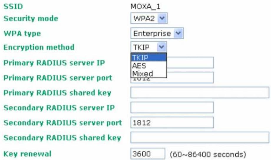
By selecting WPA type as Enterprise, you can use EAP (Extensible Authentication Protocol), a framework authentication protocol used by 802.1X to provide network authentication. In these Enterprise-level security modes, a back-end RADIUS (Remote Authentication Dial-In User Service) server is needed if IEEE 802.1X functionality is enabled in WPA/WPA2. The IEEE 802.1X protocol also offers the possibility of carrying out an efficient connection authentication in a large-scaled network. It is not necessary to exchange keys or pass phrases.
WLAN 1 WLAN Security Settings
bar
| Category | Value | |---|---| | SSID | MOXA_1 | | Security mode | WPA2 | | WPA type | Enterprise | | Encryption method | TKIP | | Primary RADIUS server IP | TKIP | | Primary RADIUS server port | AES Mixed | | Primary RADIUS shared key | | | Secondary RADIUS server IP | | | Secondary RADIUS server port | 1812 | | Secondary RADIUS shared key | | | Key renewal | 3600 (60~86400 seconds)WPA Type
| Setting Description Factory Default | ||||
| Personal | Provides WPA and WPA2 | Pre-Shared | Personal | Key-enabled |
| Enterprise Provides enterprise-level security for WPA and WPA2 | ||||
Encryption method
| Setting Description Factory Default | ||
| TKIP | Temporal Key Integrity Protocol is enabled | TKIP |
| AES | Advance Encryption System is enabled | |
| Mixed* Provides TKIP | broadcast key and TKIP+AES unicast key for some legacy AP clients. This option is rarely used. *This option is available in Redundant AP, AP, or Master mode only, and cannot support AES-enabled clients. | |
Primary/ Secondary RADIUS server IP
| Setting Description Factory Default | ||
| The IP address of RADIUS server | Specifies the delegated RADIUS server for EAP | None |
Primary/ Secondary RADIUS port
| Setting Description Factory Default | ||
| Port number Specifies the port number of the delegated RADIUS server | 1812 | |
Primary/ Secondary RADIUS shared key
| Setting Description Factory Default | ||
| Max. 31 characters The secret key shared between AP and RADIUS server | None | |
Key renewal
| Setting Description Factory Default | ||
| 60 – 86400 seconds(1 minute to 1 year) | Specifies the time period of groupkey renewal | 3600 (seconds) |
WPA/WPA2-Enterprise (for Redundant Client, Client, or Slave mode)
In a client role, the AWK-5222 can support three EAP methods (or EAP protocols ): EAP-TLS, EAP-TTLS, and EAP-PEAP, corresponding to WPA/WPA-Enterprise settings on the AP side.
WLAN 1 WLAN Security Settings
SSID
Security mode
WPA type
Encryption method
EAP protocol
MOXA_1
WPA2
Enterprise
TKIP
TLS
TLS
TTLS
PEAP
Encryption method
| Setting Description Factory Default | ||
| TKIP | Temporal Key Integrity Protocol is enabled | TKIP |
| AES | Advance Encryption System is enabled | |
EAP Protocol
| Setting Description Factory Default | ||
| TLS | Specifies Transport Layer Security protocol | TLS |
| TTLS | Specifies Tunneled Transport Layer Security | |
| PEAP | Specifies Protected Extensible Authentication Protocol, or Protected EAP | |
Before choosing the EAP protocol for your WPA/WPA2-Enterprise settings on the client end, please contact the network administrator to make sure the system supports the protocol on the AP end. Detailed information on these three popular EAP protocols is presented in the following sections:
EAP-TLS
TLS is the standards-based successor to the Secure Socket Layer (SSL). It can establish a trusted communication channel over a distrusted network. TLS provides mutual authentication through certificate exchange. EAP-TLS is also secure to use. You are required to submit a digital certificate to the authentication server for validation, but the authentication server must also supply a certificate.
You can use WLAN 1/2 → WLAN Certificate Settings to import your WLAN certificate and enable EAP-TLS on the client end.
WLAN 1 WLAN Security Settings
| SSID | MOXA_1 |
| Security mode | WPA2 |
| WPA type | Enterprise |
| Encryption method | TKIP |
| EAP protocol | TLS |
| Certificate issued to | N/A |
| Certificate issued by | N/A |
| Certificate expiration date | N/A |
You can check the current certificate status in Current Status if it is available.
Certificate issued to: shows the certificate user.
Certificate issued by: shows the certificate issuer.
Certificate expiration date: indicates when the certificate gets invalid.
EAP-TTLS
It is usually much easier to re-use existing authentication systems, such as a Windows domain or Active Directory, LDAP directory, or Kerberos realm, rather than creating a parallel authentication system. As a result, TTLS (Tunneled TLS) and PEAP (Protected EAP) are used to support the use of so-called “legacy authentication methods.”
TTLS and PEAP work in a similar way. First, they establish a TLS tunnel, like EAP-TLS, and validate whether the network is trustworthy with digital certificates on the authentication server. This step is run to establish a tunnel that protects the next step (or "inner" authentication) so it is sometimes referred to as the "outer" authentication. Then the TLS tunnel is used to encrypt an older authentication protocol that authenticates the user for the network.
As you can see, digital certificates are still needed for the outer authentication in a simplified form. Only a small number of certificates are required, which can be generated by a small certificate authority. Certificate reduction makes TTLS and PEAP much more popular than EAP-TLS.
The AWK-5222 provides some non-cryptographic EAP methods including PAP, CHAP, MS-CHAP, and MS-CHAP-V2. These EAP methods are not recommended for direct use on wireless networks. However, they may be useful as inner authentication methods with TTLS or PEAP.
Because the inner and outer authentications can use distinct user names in TTLS and PEAP, you can use an anonymous user name for the outer authentication, while the true user name is shown only through the encrypted channel. Remember, not all client software supports anonymous altercation. Confirm this with the network administrator before you enable identity hiding in TTLS and PEAP.
WLAN 1 WLAN Security Settings
| SSID | MOXA_1 |
| Security mode | WPA2 |
| WPA type | Enterprise |
| Encryption method | TKIP |
| EAP protocol | TTLS |
| TTLS inner authentication | MS-CHAP-V2 |
| Anonymous name | PAP |
| CHAP | |
| User name | MS-CHAP |
| MS-CHAP-V2 | |
| Password |
TTL Inner Authentication
| Setting Description Factory Default | ||
| PAP | Password Authentication Protocol is used | MS-CHAP-V2 |
| CHAP | Challenge Handshake Authentication Protocol is used | |
| MS-CHAP Microsoft CHAP is used | ||
| MS-CHAP-V2 Microsoft CHAP version 2 is used | ||
Anonymous
| Setting Description Factory Default | ||
| Max. 31 characters A distinct name used for outer authentication | None | |
User name & Password
| Setting Description Factory Default | ||
| User name and password | used ininner authentication | None |
PEAP
There are a few differences in the inner authentication procedures for TTLS and PEAP. TTLS uses the encrypted channel to exchange attribute-value pairs (AVPs), while PEAP uses the encrypted channel to start a second EAP exchange inside of the tunnel. The AWK-5222 provides
MS-CHAP-V2 merely as an EAP method for inner authentication.
WLAN 1 WLAN Security Settings
| SSID | MOXA_1 |
| Security mode | WPA2 |
| WPA type | Enterprise |
| Encryption method | TKIP |
| EAP protocol | PEAP |
| Inner EAP protocol | MS-CHAP-V2 |
| Anonymous name | MS-CHAP-V2 |
| User name | |
| Password |
Inner EAP protocol
| Setting Description Factory Default | |
| MS-CHAP-V2 Microsoft CHAP version 2 is used MS-CHAP-V2 | |
Anonymous
| Setting Description Factory Default | ||
| Max. 31 characters A distinct name used for outer authentication | None | |
User name & Password
| Setting Description Factory Default | ||
| User name and password | used ininner authentication | None |
Advanced Wireless Settings
Additional wireless-related parameters are presented in this section to help you set up your wireless network in detail.
WLAN 1 Advanced Wireless Settings
| Transmission rate | Auto | |
| Transmission power | Full | |
| Beacon interval | 100 | (40~1000ms) |
| DTIM interval | 1 | (1~15) |
| Fragmentation threshold | 2346 | (256~2346) |
| RTS threshold | 2346 | (256~2346) |
| Transmission distance | 500 | (500 ~ 10000m) |
| Transmission enhancement | Disable | |
| Antenna | Main | |
| EAPOL version | 1 |
Transmission Rate
| Setting Description | tion Factory Default | |
| Auto AWK-5222 will sense | sense and adjust the data rate automatically | Auto |
| Available rates User can | manually select a target transmission data rate |
Transmission Power
| Setting Description Factory Default | ||
| Auto | Specifies wireless signal coverage by automatically selecting the strength of Tx power | Full |
| Full Equivalent to 100% | of maximum Tx power | |
| High Equivalent to 75% | of maximum Tx power | |
| Medium Equivalent to 50% | of maximum Tx power | |
| Low Equivalent to 25% | of maximum Tx power | |
Beacon Interval (for Redundant AP, AP, Master mode only)
| Setting Description Factory Default | ||
| Beacon Interval(40-1000 ms) | This value indicates the frequency interval of the beacon | 100 (ms) |
DTIM Interval (for Redundant AP, AP, Master mode only)
| Setting Description Factory Default | ||
| Data Beacon Rate(1-16384) | This value indicates how often the AWK-5222 sends out a Delivery Traffic Indication Message | 1 |
Fragment threshold
| Setting Description Factory Default | ||
| Fragment Length(256-2346) | This parameter specifies the maximum size a data packet before splitting and creating another new packet | 2346 |
RTS threshold
| Setting Description Factory Default | ||
| RTS/CTS Threshold(256-2346) | This setting determines how large a packet can be before the Access Point coordinates transmission and reception to ensure efficient communication | 2346 |

NOTE
You can refer to the related glossaries in Chapter 5 for more detailed information about the above-mentioned settings. By setting these parameters properly, you can better tune the performance of your wireless network.
Transmission distance
| Setting Description Factory Default | ||
| Distance or max. range for transmission (500-10000m) | The distance specifies the transmission distance or max. range between two AWK devices. This parameter should be set properly, especially for long-distance communication. | 500 |
Transmission enhancement
| Setting Description Factory Default | ||
| Enable/Disable This setting can enhance communication by strengthening the AWK-5222's transmission power. It is quite useful for long-distance transmission or countering environmental interference. The user has to carefully evaluate and measure the transmission power of whole system, and make sure it is still below the regulative limitation. | Disable | |

NOTE
Make sure the same Transmission distance parameters are set in both AP and Client sides, and both Master and Slave. When this parameter is more than 500, an optimal algorithm will be
enabled to support long-distance transmission.
Transmission enhancement is also recommended to enable communication at both ends when long-distance transmission is required. A high-gain antenna installed at a fixed antenna connector can also improve performance. (Select Antenna at MAIN or AUX.)
Antenna
| Setting Description | Factory Default | |
| Auto | The AWK-5222 uses four antennas (two MAIN and two AUX) and enables the diversity function for reducing multipath effect. | Auto |
| MAIN 1 and MAIN 2 | Diversity function is disabled. Only MAIN 1 and 2 antenna is in use. | |
| AUX 1 and AUX 2 | Diversity function is disabled. Only AUX 1 and 2 antenna is in use. |
EAPOL Version
| Setting Description Factory Default | ||
| 1 EAPOL version 1 was | standardized in the 2001 version of 802.1X, which is much more commonly implemented. | 1 |
| 2 EAPOL version 2 was | specified in 802.1X-2004. | |
Turbo Roaming (for AP-Client operation mode's Client mode only)
| Setting Description Factory Default | ||
| Enable/ Disable Moxa's | Turbo Roaming can enable rapid handover when the AWK-5222, as a client, roams among a group of APs. | Disable |
When Turbo Roaming is enabled, RF type and Scan channels will be shown as follows. RF type shows the current RF type, which this client is using now. You can set up Scan channels for the APs among which this client is going to roam. There are three Scan channels available. Please note that the Scan channels may need to be modified when the RF type is changed. (For example, channel 36 is not available in B, G or B/G Mix mode.)
Turbo roaming
RF type
Scan channels
Enable
B/G Mixed



When EAP-TLS is used, a WLAN Certificate will be required at the client end to support WPA/WPA2-Enterprise. The AWK-5222 can support the PKCS #12, also known as Personal Information Exchange Syntax Standard, certificate formats that define file formats commonly used to store private keys with accompanying public key certificates, protected with a password-based symmetric key.
WLAN Certificate Settings Import (for EAP-TLS in Client mode only)
Current status
Certificate issued to
Certificate issued by
Certificate expiration date
Current Status displays information for the current WLAN certificate, which has been imported into the AWK-5222. Nothing will be shown if no certificate is available.
Certificate issued to: shows the certificate user
Certificate issued by: shows the certificate issuer
Certificate expiration date: indicates when the certificate gets invalid
You can import a new WLAN certificate in Import WLAN Certificate by following these steps in order:
- Input the corresponding password (or key) in the Certificate private password field. Then click Submit to set the password.
- You can see the password displayed in the Certificate private password field. Then click on the Browse button in Select certificate/key file and select the certificate file.
- Click Upload Certificate File to import the certificate file. If it succeeds, you can see the information uploaded in Current Certificate. If it fails, you may need to return to step 1 to set the password correctly and then import the certificate file again.
Step 1:
Certificate private password
Submit
Step 2:
Select certificate/key file
Upload Certificate File

NOTE
The WLAN certificate will remain after the AWK-5222 reboots. Even though it is expired, it can still be seen on Current Certificate.
Advanced Settings
Several advanced functions are available to increase the functionality of your AWK-5222 and wireless network system. The DHCP server helps you deploy wireless clients efficiently. Packet filters provide security mechanisms, such as firewalls, in different network layers. Moreover, the AWK-5222 can support STP/RSTP protocol to increase the reliability across the entire network. In additional, SNMP support can ease the network management via SNMP protocols.
DHCP Server (for AP-Client operation mode's AP mode only)
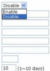
DHCP (Dynamic Host Configuration Protocol) is a networking protocol that allows administrators to assign temporary IP addresses to network computers by “leasing” an IP address to a user for a limited amount of time, instead of assigning permanent IP addresses.
The AWK-5222 can act as a simplified DHCP server and easily assign IP addresses to your wireless clients by responding to the DHCP requests from the client ends. The IP-related parameters you set on this page will also be sent to the client.
You can also assign a static IP address to a specific client by entering its MAC address. The AWK-5222 provides a Static DHCP mapping list with up to 16 entities. Be reminded to check the Active check box for each entity to activate the setting.
You can check the IP assignment status under Status → DHCP Client List.
DHCP Server (for AP mode only)
DHCP server
Default gateway
Subnet mask
Primary DNS server
Secondary DNS server
Start IP address
Maximum number of users
Client lease time
Static DHCP mapping
| No | Active | IP address | MAC address |
| 1 | |||
| 2 | |||
| 3 | |||
| 4 |
DHCP server (AP only)
| Setting Description Factory Default | |
| Enable Enables AWK-5222 as a DHCP server | Disable |
| Disable Disable DHCP server function |
Default gateway
| Setting Description Factory Default | ||
| IP address of a default gateway | The IP address of the router that connects to an outside network | None |
Subnet mask
| Setting Description Factory Default | ||
| subnet mask Identifies the type of sub-network (e.g., 255.255.0.0 for a Class B network, or 255.255.255.0 for a Class C network) | None | |
Primary/ Secondary DNS server
| Setting Description Factory Default | ||
| IP address of Primary/Secondary DNS server | The IP address of the DNS Server used by your network. After entering the DNS Server's IP address, you can use URL as well. The Secondary DNS server will be used if the Primary DNS server fails to connect. | None |
Start IP address
| Setting Description Factory Default | ||
| IP address Indicates the | IP address whichAWK-5222 can start assigning. | None |
Maximum number of users
| Setting Description Factory Default | ||
| 1 – 999 Specifies how many IP address can be assigned continuously | None | |
Client lease time
| Setting Description Factory Default | ||
| 1 – 10 days The lease time for which an IP address is assigned. The IP address may go expired after the lease time is reached. | 10 (days) | |
Packet Filters
The AWK-5222 includes various filters for IP-based packets going through LAN and WLAN interfaces. You can set these filters as a firewall to help enhance network security.
MAC Filter
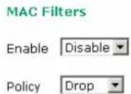
The AWK-5222's MAC filter is a policy-based filter that can allow or filter out IP-based packets with specified MAC addresses. The AWK-5222 provides 8 entities for setting MAC addresses in your filtering policy. Remember to check the Active check box for each entity to activate the setting.
| No | Active | Name | MAC address |
| 1 | |||
| 2 | |||
| 3 |
Enable
| Setting Description Factory Default | |||
| Enable | Enables | MAC | Disable filter |
| Disable Disables MAC filter | |||
Policy
| Setting Description | Factory Default | |
| Accept Only the packets | fitting the entities on list can be allowed. | Drop |
| Drop Any packet fitting | the entities on list will be denied. |

ATTENTION
Be careful when you enable the filter function:
Drop + "no entity on list is activated" = all packets are allowed
Accept + "no entity on list is activated" = all packets are denied
IP Protocol Filter
The AWK-5222's IP protocol filter is a policy-based filter that can allow or filter out IP-based packets with specified IP protocol and source/destination IP addresses.
The AWK-5222 provides 8 entities for setting IP protocol and source/destination IP addresses in your filtering policy. Four IP protocols are available: All, ICMP, TCP, and UDP. You must specify either the Source IP or the Destination IP. By combining IP addresses and netmasks, you can specify a single IP address or a range of IP addresses to accept or drop. For example, "IP address 192.168.1.1 and netmask 255.255.255.255" refers to the sole IP address 192.168.1.1. "IP address 192.168.1.1 and netmask 255.255.255.0" refers to the range of IP addresses from 192.168.1.1 to 192.168.255. Remember to check the Active check box for each entity to activate the setting.
IP Protocol Filters
Enable Disable
Policy Drop
| No | Active | Protocol | Source IP | Source netmask | Destination IP | Destination netmask |
| 1 | All | |||||
| 2 | All | |||||
| 3 | All |
Enable
| Setting Description Factory Default | |
| Enable Enables IP protocol filter | Disable |
| Disable Disables IP protocol filter |
Policy
| Setting Description Factory Default | ||
| Accept Only the packets | fitting the entities on the list can be allowed | Drop |
| Drop Any packet fitting | the entities on the list will be denied | |

ATTENTION
Be careful when you enable the filter function:
Drop + “no entity on list is activated” = all packets are allowed.
Accept + “no entity on list is activated” = all packets are denied.
TCP/UDP Port Filter
The AWK-5222's TCP/UDP port filter is a policy-based filter that can allow or filter out TCP/UDP-based packets with a specified source or destination port.
The AWK-5222 provides 8 entities for setting the range of source/destination ports of a specific protocol. In addition to selecting TCP or UDP protocol, you can set either the source port, destination port, or both. The end port can be left empty if only a single port is specified. Of course, the end port cannot be larger than the start port.
The Application name is a text string that describes the corresponding entity with up to 31 characters. Remember to check the Active check box for each entity to activate the setting.
TCP/UDP Port Filters
Enable Disable
Policy Drop
| No | Active | Source port | Destination port | Protocol | Application name |
| 1 | TCP | ||||
| 2 | TCP | ||||
| 3 | TCP |
Enable
| Setting Description Factory Default | ||
| Enable | Enables TCP/UDP port filter | Disable |
| Disable | Disables TCP/UDP port filter | |
Policy
| Setting Description Factory Default | ||
| Accept | Only the packets fitting the entities on list can be allowed. | Drop |
| Drop | Any packet fitting the entities on list will be denied. | |

ATTENTION
Be careful when you enable the filter function:
Drop + "no entity on list is activated" = all packets are allowed
Accept + "no entity on list is activated" = all packets are denied
RSTP Settings (for Master or Slave mode only)
AWK-5222 supports IEEE802.1D Spanning Tree Protocol and IEEE802.1w Rapid STP standards. In addition to eliminating unexpected path looping, STP/RSTP can provide a backup path recovery if a wired/ wireless path fails accidentally. The reliability and availability can increase because this fail-over function.
AWK-5222's STP/RSTP feature is disabled by default. To be completely effective, you must enable RSTP/STP on every AWK-5222 connected to your network.
The following figures indicate which Spanning Tree Protocol parameters can be configured. A more detailed explanation of each parameter is given below the figure.
RSTP Settings (for Master or Slave mode only)
| RSTP status | ---- |
| Bridge priority | 32768 |
| Hello time | 2 (1~10 seconds) |
| Forwarding delay | 15 (4~30 seconds) |
| Max age | 20 (6~40 seconds) |
| No | Enable RSTP | Port priority | Port cost | Edge port | Status |
| 1 (LAN1) | 128 | 200000 | --- | ||
| 2 (LAN2) | 128 | 200000 | --- | ||
| 3 (WLAN 1 : Master) | 128 | 2000000 | --- | ||
| 4 (WLAN 2 : Slave) | 128 | 2000000 | --- |
RSTP status
This field will appear only when selected to operate STP/RSTP. It indicates whether this AWK-5222 is the Root of the Spanning Tree (the root is determined automatically) or not.
Bridge priority
| Setting Description Factory Default | ||
| Numerical value selected by user | You can increase the bridge priority by selecting a lower number. A higher bridge priority brings a greater chance of being established as the root of the Spanning Tree topology. | 32768 |
Hello time
| Setting Description Factory Default | ||
| Numerical value input by user(1 – 10 seconds) | The root of the Spanning Tree topology periodically sends out a “hello” message to other devices on the network to check if the topology is healthy. Hello time indicates how often the root sends hello messages. | 2 (seconds) |
Forwarding delay
| Setting Description Factory Default | ||
| Numerical value input by user(4 – 30 seconds) | The amount of time this device waits before checking to see if it should change to a different topology. | 15 (seconds) |
Max. age
| Setting Description Factory Default | ||
| Numerical value input by user(6 – 40 seconds) | As a non-root role, if the device has not received a hello message from the root longer than Max. age, it will reconfigure itself as a root. Once two or more devices on the network are recognized as a root, the devices will renegotiate to set up a new Spanning Tree topology. | 20 (seconds) |
Enable RSTP
| Setting Description Factory Default | ||
| Enable/ disable Enables | or disables the port as a node on the Spanning Tree topology. | Disable (unchecked) |
Port priority
| Setting Description Factory Default | ||
| Numerical value selected by user | Increase this port's priority as a node on the Spanning Tree topology by inputting a lower number. | 128 |
Port cost
| Setting Description Factory Default | ||
| Enable/ Disable Input a | higher cost to indicate that this port is less suitable as a node for the Spanning Tree topology | 2000000 |
Edge port
| Setting Description Factory Default | ||
| Checked/ unchecked Sets a port, which no BPDU expectedly goes through, as an edge port | unchecked, except WLAN1/2 ports | |

NOTE
We recommend you set an edge port for the port, which is connected to a non-STP/RSTP sub-network or an end device (PLC, RTU, etc.) as opposed to network equipment. This can prevent unnecessary waiting and negotiation of STP/RSTP protocol, and accelerate system initialization. When an edge port receives BPDUs, it can still function as an STP/RSTP port and start negotiation.
Setting an edge port is different from disabling STP/RSTP on a port. If you disable STP/RSTP, a port will not deal with STP/RSTP BPDUs at all.
Port Status
Port Status indicates the current Spanning Tree status of this port. Use Forwarding for normal transmission, or Blocking to block transmission.
SNMP Agent
The AWK-5222 supports SNMP V1/V2c/V3. SNMP V1 and SNMP V2c use a community string match for authentication, which means that SNMP servers access all objects with read-only or read/write permissions using the community string public/private (default value). SNMP V3, which requires you to select an authentication level of MD5 or SHA, is the most secure protocol. You can also enable data encryption to enhance data security.
The AWK-5222's MIB can be found in the software CD and supports reading the attributes via SNMP. (Only get method is supported.)
SNMP security modes and security levels supported by the AWK-5222 are shown in the following table. Select the security mode and level that will be used to communicate between the SNMP agent and manager.
| Protocol Version | Setting on UI web page | Authentication Type | Data Encryption | Method |
| SNMP V1, V2c | V1, V2c Read Community | Community string | No | Use a community string match for authentication |
| V1, V2c Write/Read Community | Community string | No | Use a community string match for authentication | |
| SNMP V3 | No-Auth | No | No | Use account with admin or user to access objects |
| MD5 or SHA | Authentication based on MD5 or SHA | No | Provides authentication based on HMAC-MD5, or HMAC-SHA algorithms. 8-character passwords are the minimum requirement for authentication. | |
| MD5 or SHA | Authentication based on MD5 or SHA | Data encryption key | Provides authentication based on HMAC-MD5 or HMAC-SHA algorithms, and data encryption key. 8-character passwords and a data encryption key are the minimum requirements for authentication and encryption. |
The following parameters can be configured on the SNMP Agent page. A more detailed explanation of each parameter is given below the following figure.
SNMP Agent
Enable
Read community
Write community
SNMP agent version
Admin auth type
Admin privacy key
Privacy key
Private MIB information
Device object ID
Disable




enterprise.8691.15.1
Enable
| Setting Description Factory Default | |||
| Enable | Enables | SNMP | Disable Agent |
| Disable | Disables | SNMP | Agent |
Read community (for V1, V2c, V3 or V1, V2c)
| Setting Description Factory Default | ||
| Read Community Use a | community string match with a maximum of 31 characters for authentication. This means that the SNMP agent can access all objects with read-only permissions using this community string. | public |
Write community (for V1, V2c, V3 or V1, V2c)
| Setting Description Factory Default | ||
| Read /Write Community | Use a community string match with a maximum of 31 characters for authentication. This means that the SNMP agent can accesses all objects with read/write permissions using this community string. | private |
SNMP agent version
| Setting Description Factory Default | ||
| V1, V2c, V3, or V1, V2c, or V3 only | Select the SNMP protocol version used to manage the switch. | V1, V2c |
Admin auth type (for V1, V2c, V3, and V3 only)
| Setting Description Factory Default | ||
| No Auth Use admin account to access objects. No authentication | No Auth | |
| MD5 Provide authentication based on the HMAC-MD5 algorithms. 8-character passwords are the minimum requirement for authentication. | ||
| SHA Provides authentication based on HMAC-SHA algorithms. 8-character passwords are the minimum requirement for authentication. | ||
Admin private key (for V1, V2c, V3, and V3 only)
| Setting Description Factory Default | ||
| Disable No data encryption | Disable | |
| DES DES-based data encryption | ||
| AES AES-based data encryption | ||
Private Key
A data encryption key is the minimum requirement for data encryption (maximum of 63 characters)
Private MIB Information Device Object ID
Also know as OID. This is the AWK-5222's enterprise value. It is fixed.
Storm Protection
In general, one host should not be allowed to occupy unlimited bandwidth, particularly when the device malfunctions. For example, so-called “broadcast storms” could be caused by an incorrectly configured topology or a malfunctioning device.
Storm Protection
Storm protection
Enable Disable
Multicast & flooding
○ Enable ◦ Disable
Storm Protection
| Setting Description Factory Default | ||
| Enable/Disable Enable or disable Broadcast Storm Protection globally for multicast packets | Enable | |
Multicast and flooding
| Setting Description Factory Default | ||
| Enable/Disable If you enable Storm Protection, the Multicast and flooding option will show up. You can Enable or Disable Broadcast Storm Protection globally for unknown multicast and unknown unicast packets. | Disable | |
Auto Warning Settings
Since industrial-grade devices are often located at the endpoints of a system, these devices will not always know what is happening elsewhere on the network. This means that these devices, including wireless APs or clients, must provide system maintainers with real-time alarm messages. Even when system administrators are out of the control room for an extended period, they can still be informed of the status of devices almost instantaneously when exceptions occur.
In addition to logging these events, the AWK-5222 supports different approaches to warn engineers automatically, such as SNMP trap, e-mail, and relay output. It also supports two digital inputs to integrate sensors into your system to automate alarms by email and relay output.
System Log
System Log Event Types
Detail information for grouped events is shown in the following table. You can check the box for Enable log to enable the grouped events. All default values are enabled (checked). The log for system events can be seen in Status → System Log.
System log Event Types
| Event group | Enable log |
| System-related events | ☑ |
| Network-related events | ☑ |
| Config-related events | ☑ |
| Power events | ☑ |
| DI events | ☑ |
| System-related events Event is triggered when... | |
| System restart (warm start) | The AWK-5222 is rebooted, such as when its settings are changed (IP address, subnet mask, etc.). |
| Network-related events | Event is triggered when... |
| LAN 1 or LAN 2 link on | The LAN port is connected to a device or network. |
| LAN 1 or LAN 2 link off | The port is disconnected (e.g., the cable is pulled out, or the opposing device shuts down). |
| Client joined/ left for WLAN 1 or WLAN 2(for Redundant AP, AP, or Master mode) | A wireless client is associated or disassociated. |
| WLAN 1 or WLAN 2 connected to AP(for Redundant Client, Client, or Slave mode) | The AWK-5222 is associated with an AP. |
| WLAN 1 or WLAN 2 disconnected(for Redundant Client, Client, or Slave mode) | The AWK-5222 is disassociated from an AP. |
| Config-related events Event is triggered when... | |
| Configuration Changed A configuration item has been changed. | |
| Configuration file import via Web Console | The configuration file is imported to the AWK-5222. |
| Console authentication failure An incorrect password is entered. | |
| Firmware upgraded The AWK-5222's firmware is updated. | |
| Power events Event is triggered when... | |
| Power 1/2 transition (On → Off) | The AWK-5222 is powered down in PWR1/2. |
| PoE transition (On → Off) | The AWK-5222 is powered down in PoE. |
| Power 1/2 transition (Off → On) | The AWK-5222 is powered via PWR1/2. |
| PoE transition (Off → On) | The AWK-5222 is powered via PoE. |
| DI events Event is triggered when... | |
| DI1/2 transition (On → Off) | Digital Input 1/2 is triggered by on to off transition |
| DI1/2 transition (Off → On) | Digital Input 1/2 is triggered by off to on transition |
Syslog
This function provides the event logs for the Syslog server. The function supports up to three configurable Syslog servers and Syslog server UDP port numbers. When an event occurs, the event will be sent as a Syslog UDP packet to the specified Syslog servers.
Syslog Event Types
Detail information for the grouped events is shown in the following table. You can check the box for Enable log to enable the grouped events. All default values are enabled (checked). Details for each event group can be found on the "System log Event Types" table on page 3-31.
Syslog Event Types
| Event group | Enable log |
| System-related events | ☑ |
| Network-related events | ☑ |
| Config-related events | ☑ |
| Power events | ☑ |
| DI events | ☑ |
Syslog Server Settings
You can configure the parameters for your Syslog servers in this page.
Syslog Server Settings
| Syslog server 1 | |
| Syslog port | 514 |
| Syslog server 2 | |
| Syslog port | 514 |
| Syslog server 3 | |
| Syslog port | 514 |
Syslog server 1/2/3
| Setting Description Factory Default | ||
| IP address Enter the IP address of the 1st/ 2nd/3rd Syslog Server | None | |
Syslog port
| Setting Description Factory Default | ||
| Port destination(1 to 65535) | Enter the UDP port of the corresponding Syslog server | 514 |
E-mail Event Types
Check the box for Active to enable the event items. All default values are deactivated (unchecked). Details for each event item can be found on the "System log Event Types" table on page 3-31.
E-mail Event Types
| Event | □ Active |
| Cold start | |
| Warm start | |
| Power 1 transition (On-->Off) | |
| Power 1 transition (Off-->On) | |
| Power 2 transition (On-->Off) | |
| Power 2 transition (Off-->On) | |
| PoE transition (On-->Off) | |
| PoE transition (Off-->On) | |
| Configuration changed | |
| Console authentication failure | |
| DI 1 transition (On-->Off) | |
| DI 1 transition (Off-->On) | |
| DI 2 transition (On-->Off) | |
| DI 2 transition (Off-->On) | |
| LAN 1 link On | |
| LAN 1 link Off | |
| LAN 2 link On | |
| LAN 2 link Off |
E-mail Server Settings
You can set up to 4 e-mail addresses to receive alarm emails from the AWK-5222. The following parameters can be configured on the E-mail Server Settings page. In addition, a Send Test Mail button can be used to test whether the Mail server and e-mail addresses work well. More detailed explanations about these parameters are given after the following figure.
E-mail Server Settings
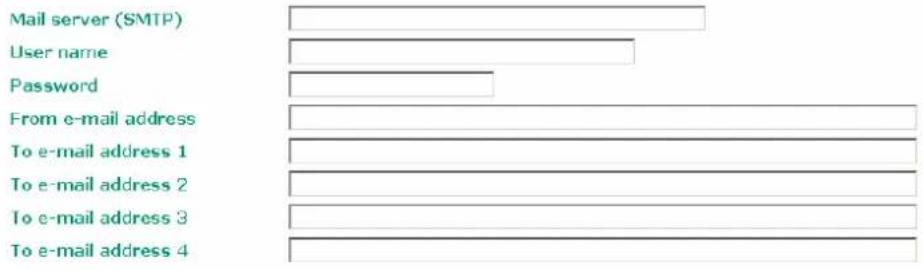
Submit
Send Test Mail
Mail server (SMTP)
| Setting Description Factory Default | ||
| IP address The IP Address of your email server. None | ||
User name & Password
| Setting Description Factory Default | ||
| User name and password used in the SMTP server | None | |
From e-mail address
| Setting Description Factory Default | ||
| Max. 63 characters | Enter the administrator's e-mail address which will be shown in the “From” field of a warning e-mail. | None |
To E-mail address 1/2/3/4
| Setting Description Factory Default | |
| Max. 63 characters Enter the receivers' e-mail addresses. None |
Relay
The AWK-5222 has one relay output, which consists of 2 terminal block contacts on the AWK-5222's top panel. These relay contacts are used to indicate user-configured events and system failure.
The two wires attached to the relay contacts form an open circuit when a user-configured event is triggered. If a user-configured event does not occur, the relay circuit will remain closed. For safety reasons, the relay circuit is kept open when the AWK-5222 is not powered.
Relay Event Types
You can check the box for Active to enable the event items. All default values are deactivated (unchecked). Details for each event item can be found in the "System log Event Types" table on page 3-31.
Relay Event Types
| Event | Active |
| Power 1 transition (On-->Off) | |
| Power 2 transition (On-->Off) | |
| PoE transition (On-->Off) | |
| DI 1 transition (On-->Off) | |
| DI 1 transition (Off-->On) | |
| DI 2 transition (On-->Off) | |
| DI 2 transition (Off-->On) | |
| LAN 1 link On | |
| LAN 1 link Off | |
| LAN 2 link On | |
| LAN 2 link Off |
Trap
Traps can be used to signal abnormal conditions (notifications) to a management station. This trap-driven notification can make your network more efficient.
Because a management station usually takes care of a large number of devices that have a large number of objects, it will be overloading for the management station to poll or send requests to query every object on every device. It would be better if the managed device agent could notify the management station by sending a message known as a trap for the event.
Trap Event Types
Trap Event Types
| Event | □ Active |
| Cold start | |
| Warm start | |
| Power 1 transition (On-->Off) | |
| Power 1 transition (Off-->On) | |
| Power 2 transition (On-->Off) | |
| Power 2 transition (Off-->On) | |
| PoE transition (On-->Off) | |
| PoE transition (Off-->On) | |
| Configuration changed | |
| Console authentication failure | |
| DI 1 transition (On-->Off) | |
| DI 1 transition (Off-->On) | |
| DI 2 transition (On-->Off) | |
| DI 2 transition (Off-->On) | |
| LAN 1 link On | |
| LAN 1 link Off | |
| LAN 2 link On | |
| LAN 2 link Off |
SNMP Trap Receiver Settings
SNMP traps are defined in SMIv1 MIBs (SNMPv1) and SMIv2 MIBs (SNMPv2c). The two styles are basically equivalent, and it is possible to convert between the two. You can set the parameters for SNMP trap receivers through the web page.
SNMP Trap Receiver Settings
1st Trap version
1st Trap server IP/name
1st Trap community
2nd Trap version
2nd Trap server IP/name
2nd Trap community
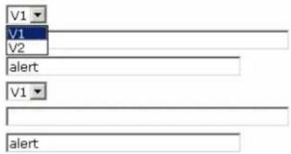
1st / 2nd Trap version
| Setting Description Factory Default | |
| V1 SNMP trap defined in SNMPv1 | V1 |
| V2 SNMP trap defined in SNMPv2 |
1st / 2nd Trap server IP/name
| Setting Description Factory Default | ||
| IP address or host name | Enter the IP address or name of the trap server used by your network. | None |
1st / 2nd Trap community
| Setting Description Factory Default | ||
| Max. 31 characters Use a community string match with a maximum of 31 characters for authentication. | alert | |
Status
Wireless Status
The status for 802.11 info parameters, such as Operation mode and Channel, are shown on the Wireless Status page. The status will refresh every 5 seconds if the Auto refresh box is checked.
Certain values for 802.11 info may not appear with different operation modes. For example, Current BSSID and RSSI are not available in Redundant AP, AP, or Master modes.
It is helpful to use the continuously updated information option on this page, such as RSSI, to monitor the signal strength of the AWK-5222 in Redundant Client, Client, or Slave modes.
Wireless Status
Auto refresh
Show status of WLAN 1 (SSID: MOXA_1)
802.11 info
| Operation mode | AP-Client - Client (WLAN 1) |
| Channel | Not connected |
| RF type | B/G Mixed |
| SSID | MOXA_1 |
| Security mode | OPEN |
| Current BSSID | N/A |
| Signal strength | |
| Transmission rate | N/A |
| Transmission power | Full |
Associated Client List (for Redundant AP, AP, or Master mode only)
Associated Client List shows all the clients that are currently associated to a particular AWK-5222. You can click Select all to select all the content in the list for further editing. You can click Refresh to refresh the list.
Associated Client List (for Redundant AP, AP, or Master mode only)
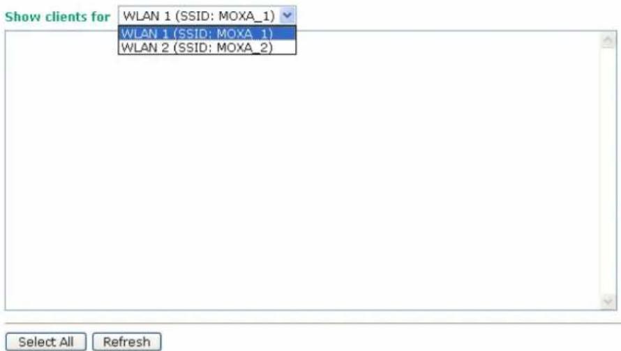
DHCP Client List (for AP mode only)
When you enable the DHCP server, the DHCP Client List shows all the clients that require and have successfully received IP assignments. You can click the Refresh button to refresh the list.
DHCP Client List
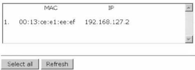
You can press Select all button to select all content in the list for further editing.
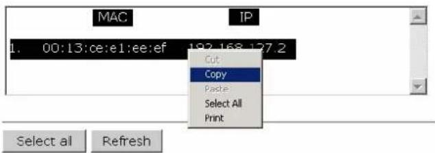
System Log
Triggered events are recorded in System Log. You can export the log contents to an available viewer by clicking Export Log. You can use the Clear Log button to clear the log contents and the Refresh button to refresh the log.
System log
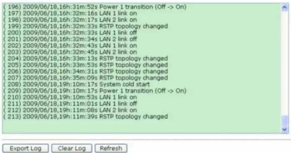
Relay Status
The status of user-configurable events can be found under Relay Status. The status will refresh every 5 seconds if the Auto refresh box is checked.
If an event is triggered, it will be noted on this list. System administrators can click Acknowledge Event when he has acknowledged the event and addressed it.
Relay Status
Auto refresh
| Relay Status | ||
| Power 1 transition (On-->Off) | --- | Acknowledge Event |
| Power 2 transition (On-->Off) | --- | Acknowledge Event |
| PoE transition (On-->Off) | --- | Acknowledge Event |
| DI 1 transition (On-->Off) | --- | Acknowledge Event |
| DI 1 transition (Off-->On) | --- | Acknowledge Event |
| DI 2 transition (On-->Off) | --- | Acknowledge Event |
| DI 2 transition (Off-->On) | --- | Acknowledge Event |
| LAN 1 link On | --- | Acknowledge Event |
| LAN 1 link Off | --- | Acknowledge Event |
| LAN 2 link On | --- | Acknowledge Event |
| LAN 2 link Off | --- | Acknowledge Event |
DI and Power Status
The status of power inputs and digital inputs is shown on this web page. The status will refresh every 5 seconds if the Auto refresh box is checked.
Din and Power status
√ Auto refresh
| Input status | On / Off |
| Power 1 status | On |
| Power 2 status | Off |
| PoE status | Off |
| DI 1 status | Off |
| DI 2 status | Off |
Maintenance
Maintenance functions provide the administrator with tools to manage the AWK-5222 and wired/wireless networks.
Console Settings
You can enable or disable access permission for the following consoles: HTTP, HTTPS, Telnet and SSH connections. For more security, we recommend you only allow access to the two secured consoles, HTTPS and SSH.
Console Settings
| HTTP console | ● Enable ○ Disable |
| HTTPS console | ● Enable ○ Disable |
| Telnet console | ● Enable ○ Disable |
| SSH console | ● Enable ○ Disable |
Submit
Ping
Ping helps to diagnose the integrity of wired or wireless networks. By inputting a node's IP address in the Destination field, you can use the ping command to make sure it exists and whether or not the access path is available.
Ping
Destination 192.168.253.2
Ping
If the node and access path are available, you will see that all packets were successfully transmitted with no loss. Otherwise, some, or even all, packets may get lost, as shown in the following figure.
Ping

PING 192.168.127.2 (192.168.127.2): 56 data bytes
--- 192.168.127.2 ping statistics --- 4 packets transmitted, 0 packets received, 100% packet loss
Firmware Upgrade
The AWK-5222 can be enhanced with more value-added functions by installing firmware upgrades. The latest firmware is available at Moxa's download center.
Before running a firmware upgrade, make sure the AWK-5222 is off-line. Click the Browse button to specify the firmware image file and click Firmware Upgrade and Restart to start the firmware upgrade. After the progress bar reaches 100%, the AWK-5222 will reboot itself.
When upgrading your firmware, the AWK-5222's other functions are forbidden.


ATTENTION
Please make sure the power source is stable when you upgrade your firmware. An unexpected power breakup may damage your AWK-5222.
Config Import Export
You can back up or restore the AWK-5222's configuration with Config Import Export.
In the Config Import section, click Browse to specify the configuration file and click Config Import button to begin importing the configuration.
Config Import

In the Config Export section, click the Config Export button and save the configuration file onto your local storage media. The configuration file is a text file and you can view and edit it with a general text-editing tool.
Config Export
Config Export
Load Factory Default
Use this function to reset the AWK-5222 and roll all settings back to the factory default values. You can also reset the hardware by pressing the reset button on the top panel of the AWK-5222.
Load Factory Default
Reset to Factory Default
Click Activate to reset all settings, including the console password, to the factory default values.
The system will be restarted immediately.
Activate
Password
You can change the administration password for each of the AWK-5222's console managers by using the Password function. Before you set up a new password, you must input the current password and reenter the new password for confirmation. For your security, do not use the default password root, and remember to change the administration password regularly.
Password
Current password
New password
Confirm password
Submit
Misc. Settings
Additional settings to help you manage your AWK-5222, are available on this page.
Misc. Settings
Reset button
● Always enable C Disable after 60 sec
Reset button
| Setting Description Factory Default | ||
| Always enable The AWK-5222's Reset button works normally. | Always enable | |
| Disable after 60 sec The | AWK-5222's Reset button will become invalid 60 seconds after the AWK-5222 completes booting. | |
Save Configuration
The following figure shows how the AWK-5222 stores the setting changes into volatile and non-volatile memory. All data stored in volatile memory will disappear when the AWK-5222 is shutdown or rebooted unless they are y. Because the AWK-5222 starts up and initializes with the settings stored in flash memory, all new changes must be saved to flash memory before restarting the AWK-5222.
This also means the new changes will not work unless you run either the Save Configuration function or the Restart function.
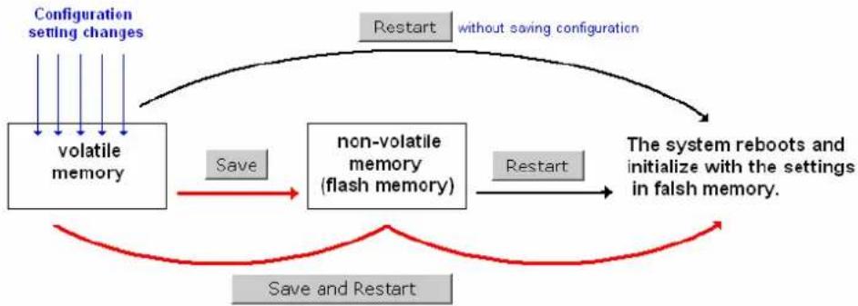
flowchart
graph TD
    A["volatile memory"] -->|Save| B["non-volatile memory (flash memory)"]
    B -->|Restart| C["The system reboots and initialize with the settings in falsh memory."]
    C --> D["Configuration setting changes"]
    D --> E["Restart without saving configuration"]
    E --> F["Save and Restart"]
After you click on Save Configuration in the left menu box, the following screen will appear. Click Save if you wish to update the configuration settings in the flash memory at this time. Alternatively, you may choose to run other functions and put off saving the configuration until later. However, the new setting changes will remain in the non-volatile memory until you save the configurations.
Save Configuration
If you have submitted any configuration changes, you must save the changes and restart the system before they take effect. Click Save to save the changes in AWK-5222-US's memory. Click Restart to activate new settings in the navigation panel.
Save
Restart
If you submitted configuration changes, you will find a blinking string in the upper right corner of the screen. After making all your changes, click the Restart function in the left menu box. One of two different screens will appear.
If you made changes recently but did not save, you will be given two options. Clicking the Restart button here will reboot the AWK-5222 directly, and all setting changes will be ignored. Clicking the Save and Restart button will apply all setting changes and then reboot the AWK-5222.
Restart
!!! Warning !!!
Click "Restart" to discard changes and reboot AWK-5222-US directly.
Click "Save and Restart" to apply all setting changes and reboot AWK-5222-US.
Restart
Save and Restart
If you run the Restart function without changing any configurations or saving all your changes, you will see just one Restart button on your screen.
Restart
!!! Warning !!!
Clicking Restart will disconnect all Ethernet connections and reboot AWK-5222-US.
Restart
You will not be able to run any of the AWK-5222's functions while the system is rebooting.
Logout
Logout helps users disconnect the current HTTP or HTTPS session and go to the Login page. For security reasons, we recommend you logout before quitting the console manager.
Logout
Click Logout button to defalut Login page.
Logout
In this chapter, we cover the following topics:
Overview
□ AWK Search Utility
➢ Installing AWK Search Utility
➢ Configuring AWK Search Utility
Overview
The Documentation & Software CD included with your AWK-5222 is designed to make the installation and configuration procedure easy and straightforward. This auto-run CD includes AWK Search Utility (to broadcast search for all AWK's accessible over the network), the AWK-5222 User's Manual, and Quick Installation Guide.
AWK Search Utility
Installing AWK Search Utility
- Click the INSTALL UTILITY button in the AWK Installation CD auto-run window to install AWK Search Utility. Once the program starts running, click Yes to proceed.
- Click Next when the Welcome screen opens to proceed with the installation.
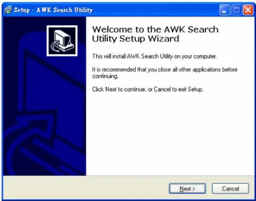
- Click Next to install program files to the default directory, or click Browse to select an alternate location.
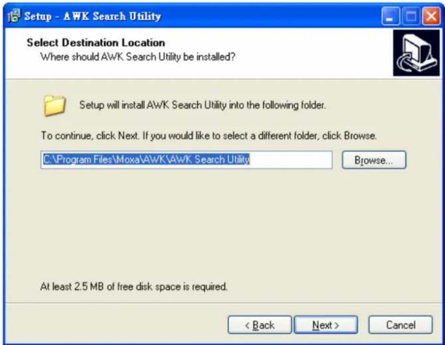
- Click Next to create the program's shortcut files to the default directory, or click Browse to select an alternate location.
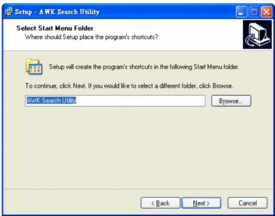
- Click Next to select additional tasks.
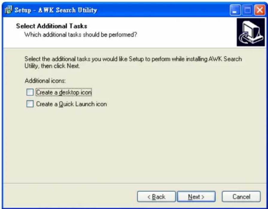
- Click Next to proceed with the installation. The installer then displays a summary of the installation options.
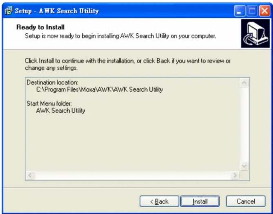
- Click Install to begin the installation. The setup window will report the progress of the installation. To change the installation settings, click Back and navigate to the previous screen.
- Click Finish to complete the installation of AWK Search Utility.
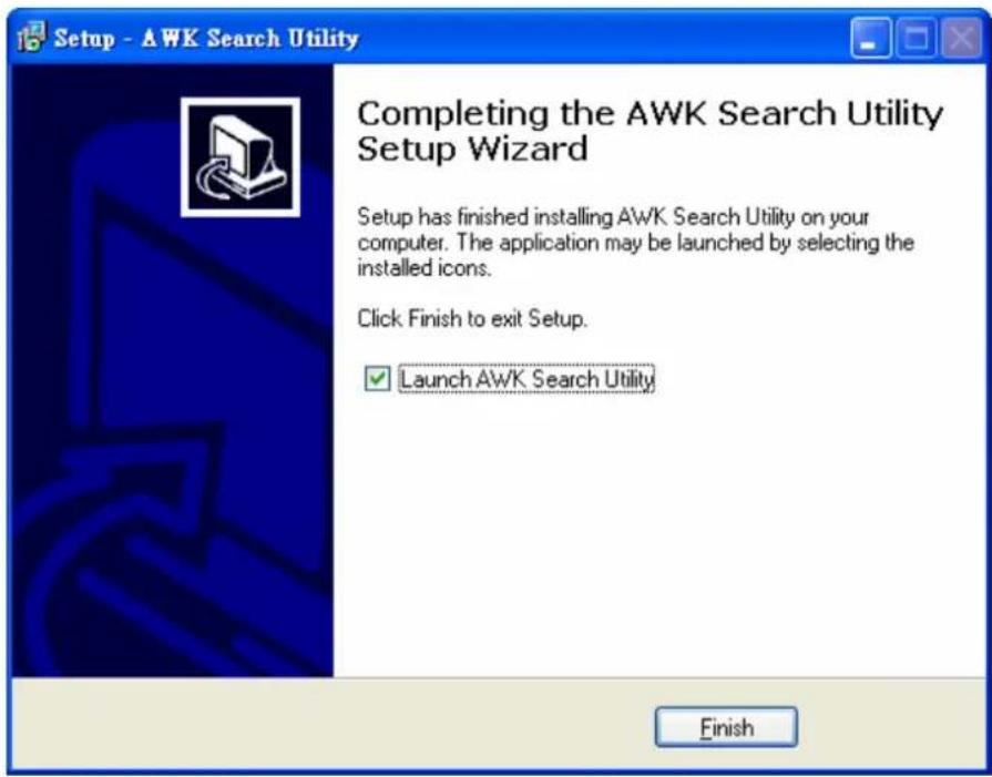
Configuring AWK Search Utility
The Broadcast Search function is used to locate all AWK-5222 APs that are connected to the same LAN as your computer. After locating an AWK-5222, you will be able to change its IP address. Since the Broadcast Search function searches by TCP packet and not IP address, it doesn't matter if the AWK-5222 is configured as an AP or Client. In either case, APs and Clients connected to the LAN will be located, regardless of whether or not they are part of the same subnet as the host.
- Start the AWK Search Utility program. When the Login page appears, select the "Search AWK only" option to search for AWKs and to view each AWK's configuration. Select the "AWK management" option to assign IPs, upgrade firmware, and locate devices.
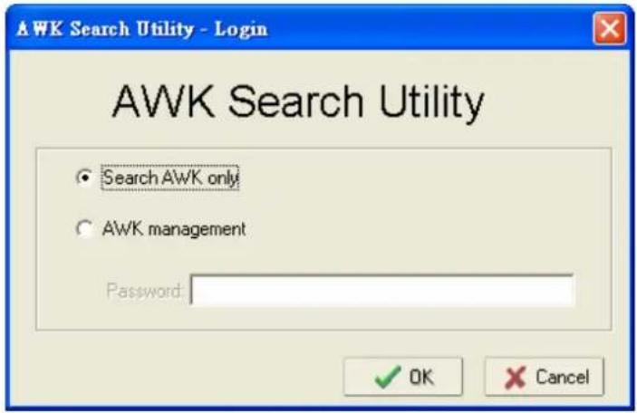
- Open the AWK Search Utility and then click the Search icon.
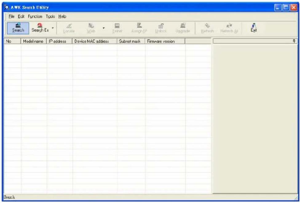
The "Searching" window indicates the progress of the search.
- When the search is complete, all AWKs that were located will be displayed in the AWK Search Utility window.
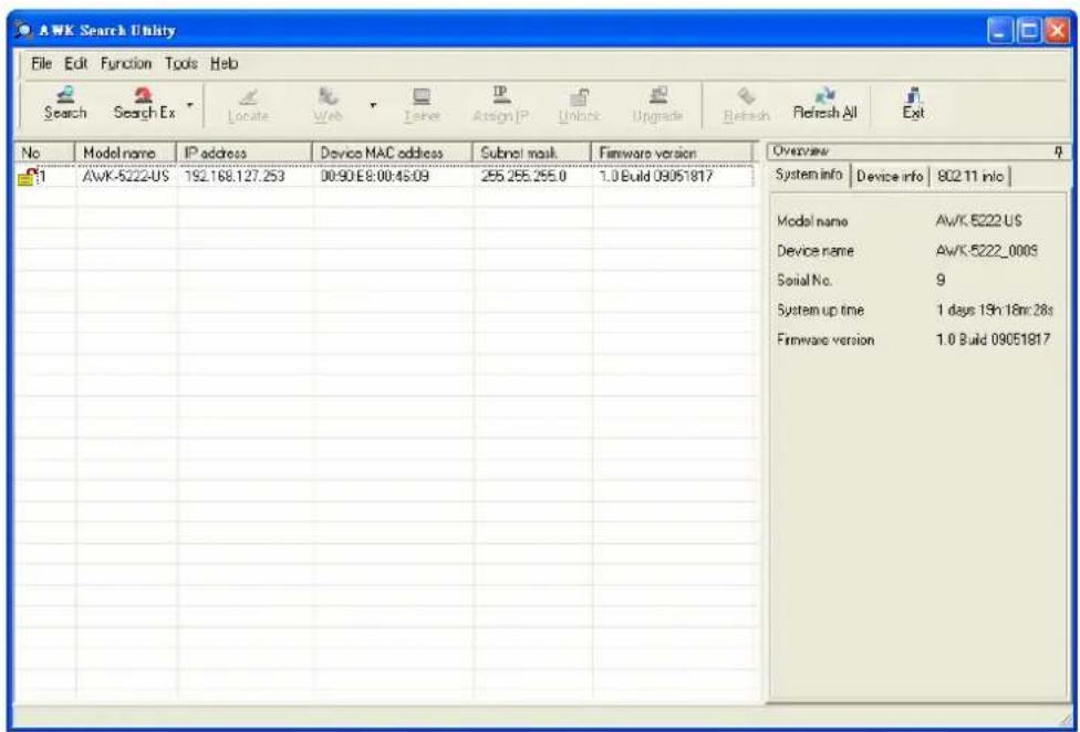
Click Locate to cause the selected device to beep.
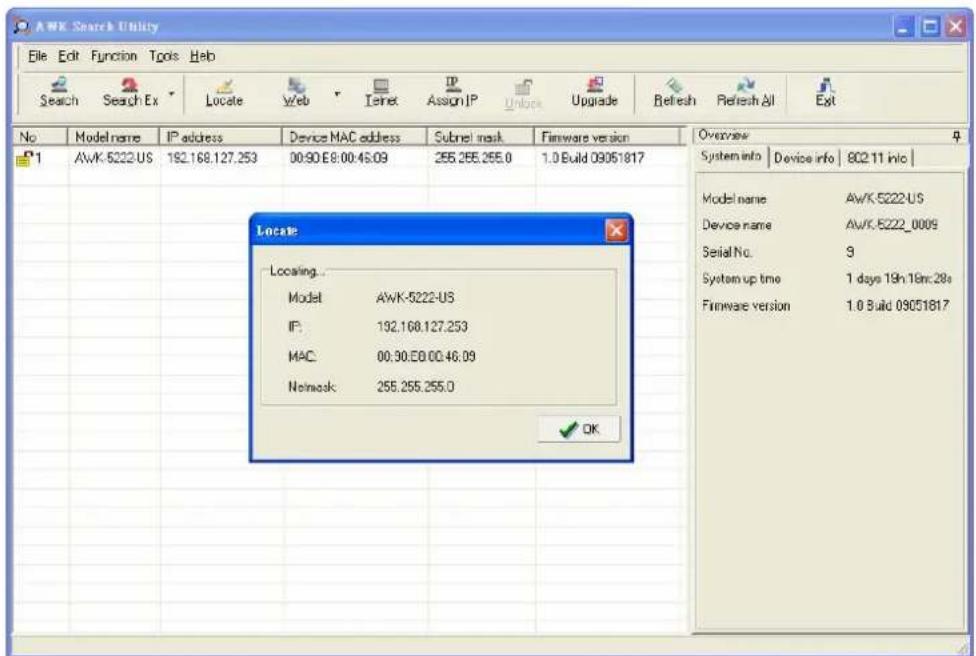
Make sure your AWK is unlocked before using the search utility's icons setting. The AWK will unlock automatically if the password is set to the default. Otherwise you must enter the new password manually.
Go to Tools → AWK login Options to manage and unlock additional AWKs.
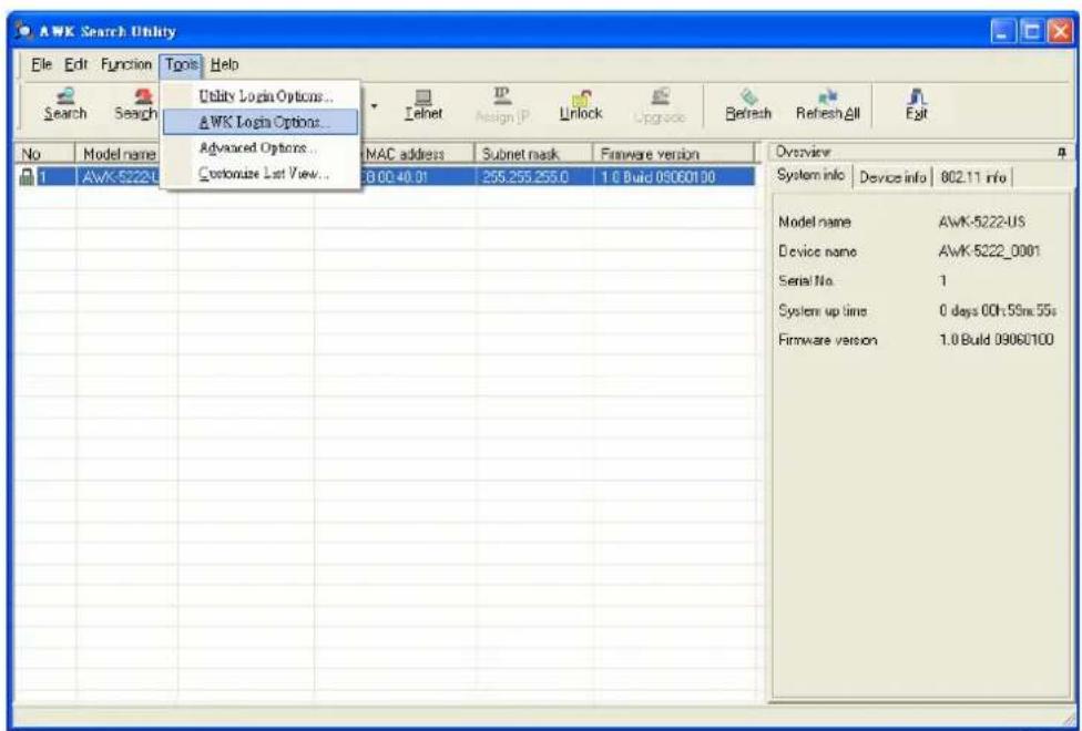
Use the scroll down list to select the MAC addresses of those AWKs you would like to manage, and then click Add. Key in the password for the AWK device and then click OK to save. If you return to the search page and search for the AWK again, you will find that the AWK will unlock automatically.

ATTENTION
For security purposes, we suggest you can change the AWK search utility login password instead of using default.
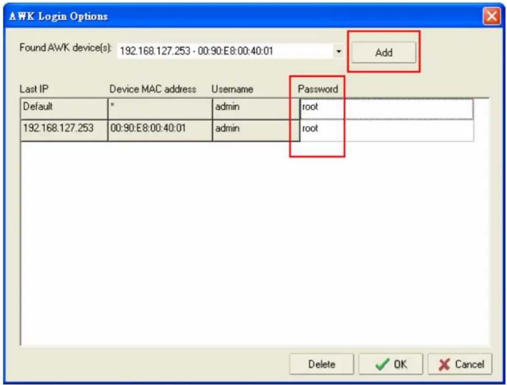
To modify the configuration of the highlighted AWK, click on the Web icon to open the web console. This will take you to the web console, where you can make all configuration changes. Refer to Chapter 3, "Using the Web Console," for information on how to use the web console.
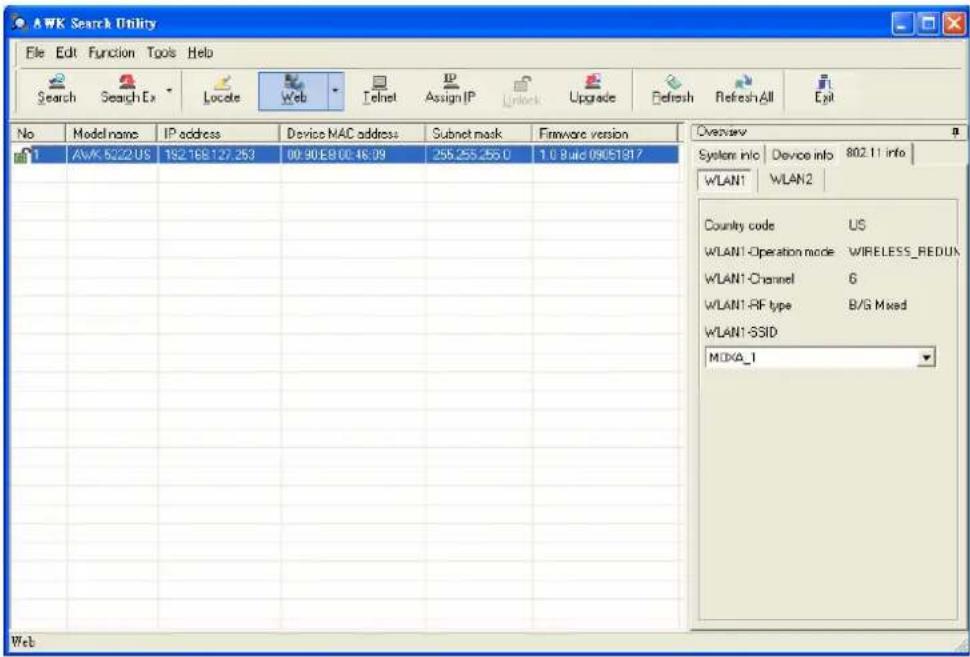
Click on Telnet if you would like to use telnet to configure your AWKs.
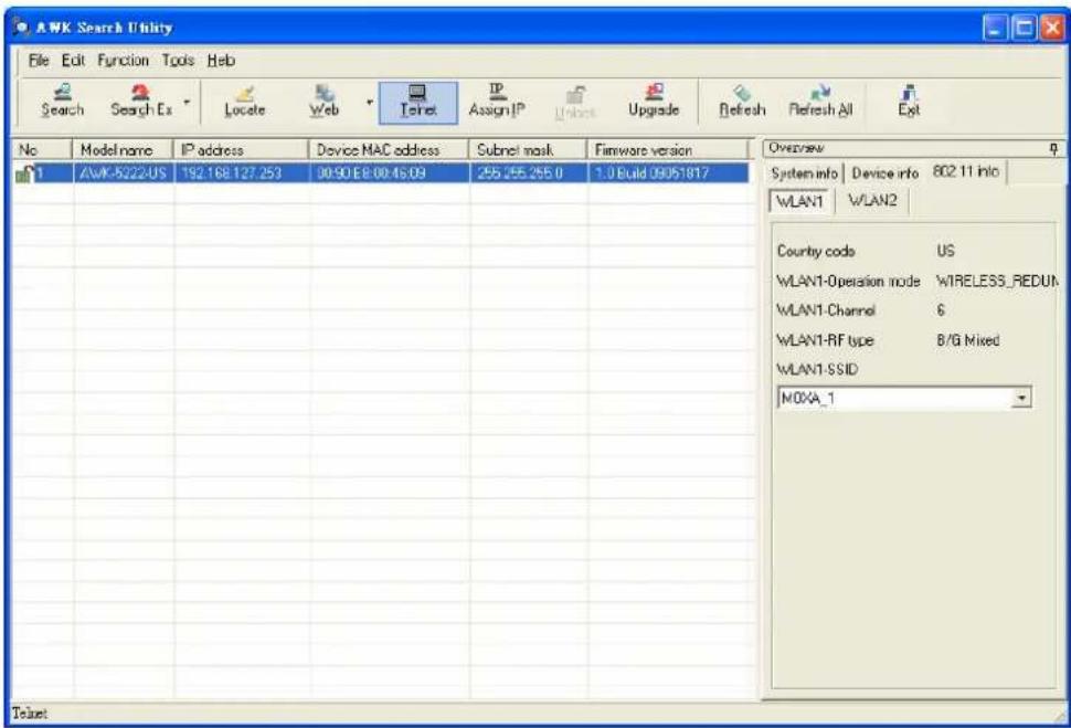
Click Assign IP to change the IP setting.
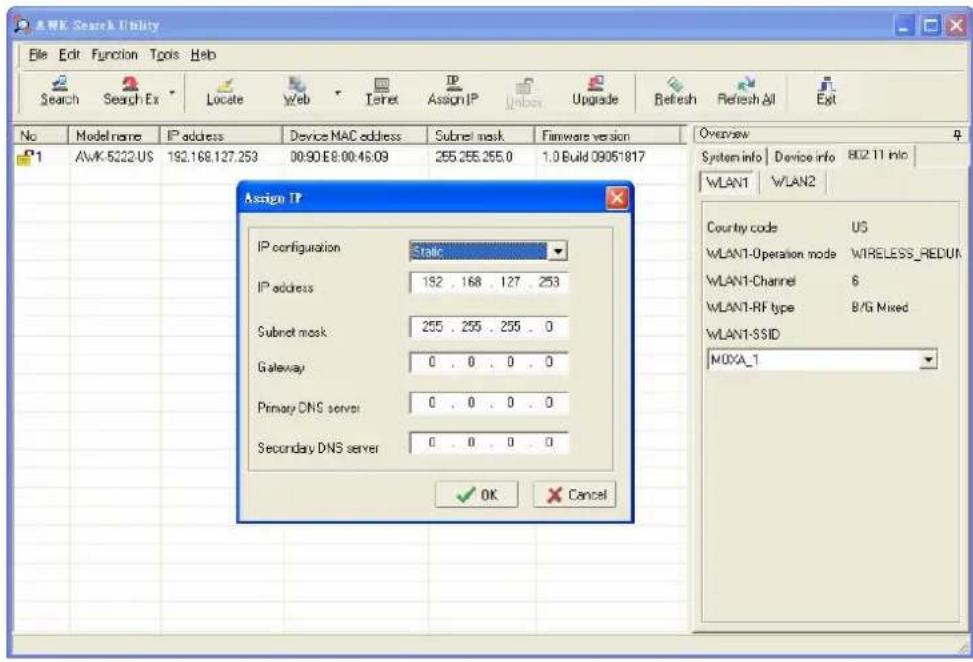
The three advanced options—Search, Connection, and Miscellaneous—are explained below:
Search
Retry count (default=5): Indicates how many times the search will be retried automatically.
Retry interval (ms): The time lapsed between retries.
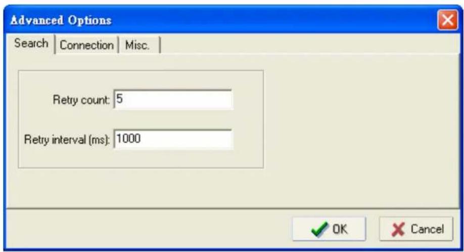
Connection
Connection timeout (secs): Use this option to set the waiting time for the Default Login, Locate, Assign IP, Upload Firmware, and Unlock to complete.
Upgrade timeout (secs): Use this option to set the waiting time for the connection to disconnect while the firmware is upgrading. Use this option to set the waiting time for the Firmware to write to flash.
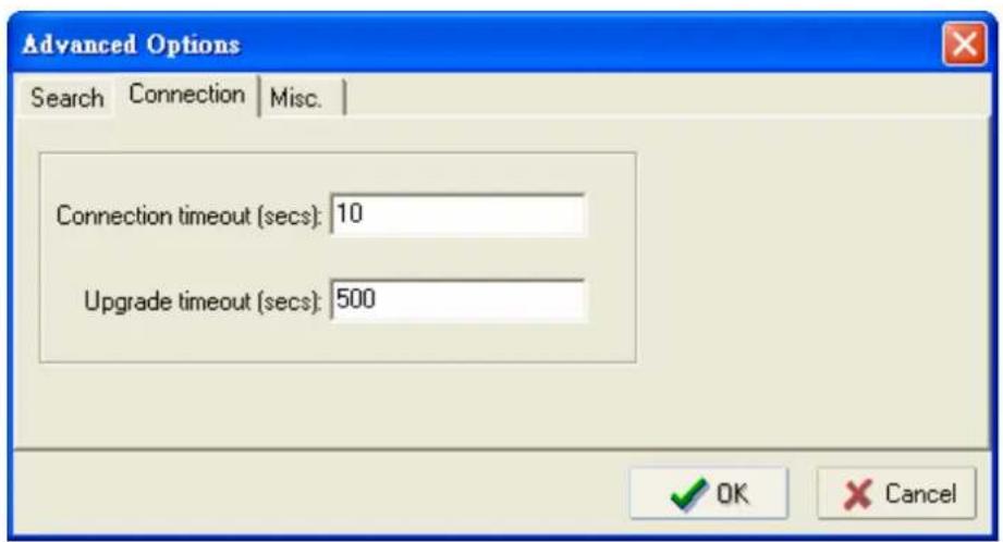
Misc.
Search on start: Checkmark this box if you would like the search function to start searching for devices after you log in to the AWK search Utility.
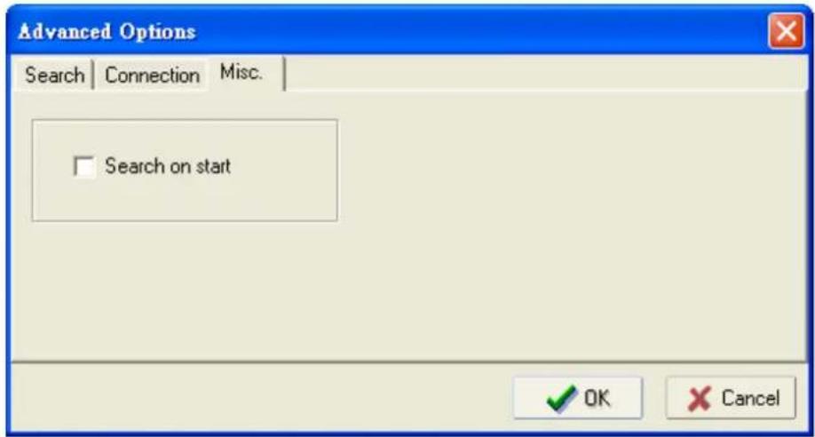
This chapter explains how to access the AWK-5222 for the first time. In addition to HTTP access, there are four ways to access AWK-5222: serial console, Telnet console, SSH console, and HTTPS console. The serial console connection method, which requires using a short serial cable to connect the AWK-5222 to a PC's COM port, can be used if you do not know the AWK-5222's IP address. The other consoles can be used to access the AWK-5222 over an Ethernet LAN, or over the Internet.
In this chapter, we cover the following topics:
☐ RS-232 Console Configuration (115200, None, 8, 1, VT100)
☐ Configuration by Telnet and SSH Consoles
☐ Configuration by Web Browser with HTTPS/SSL
□ Disabling Telnet and Browser Access

ATTENTION
- You CANNOT connect to the AWK-5222 by two ore more of these console configurations simultaneously.
- You can connect to the AWK-5222 simultaneously by web browser and serial/Telnet/SSH console. However, we strongly suggest that you do NOT use more than one connection method at the same time. Following this advice will allow you to maintain better control over the configuration of your AWK-5222.
RS-232 Console Configuration (115200, None, 8, 1, VT100)
The serial console connection method, which requires using a short serial cable to connect the AWK-5222 to a PC's COM port, can be used if you do not know the AWK-5222's IP address. It is also convenient to use serial console configurations when you cannot access the AWK-5222 over Ethernet LAN, such as in the case of LAN cable disconnections or broadcast storming over the LAN.

ATTENTION
Do not use the RS-232 console manager when the AWK-5222 is powered at reversed voltage (ex. -48VDC), even though reverse voltage protection is supported.
If you need to connect the RS-232 console at reversed voltage, Moxa's TCC-82 isolator is your best solution.

NOTE
We recommend using Moxa PComm (Lite) Terminal Emulator, which can be downloaded free of charge from Moxa's website.
Before running PComm Terminal Emulator, use an RJ45 to DB9-F (or RJ45 to DB25-F) cable to connect the AWK-5222's RS-232 console port to your PC's COM port (generally COM1 or COM2, depending on how your system is set up). After installing PComm Terminal Emulator, take the following steps to access the RS-232 console utility.
-
From the Windows desktop, open the Start menu and start PComm Terminal Emulator in the PComm (Lite) group.
-
Select Open under Port Manager to open a new connection.
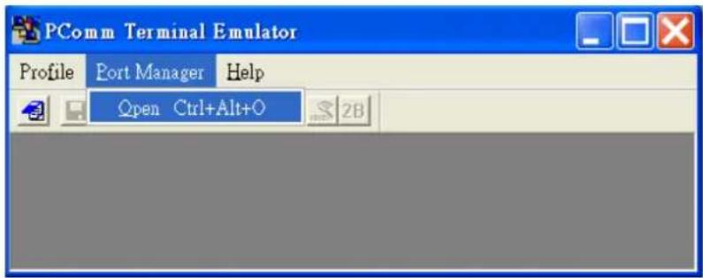
- The Communication Parameter page of the Property window opens. Select the appropriate COM port for Console Connection, 115200 for Baud Rate, 8 for Data Bits, None for Parity, and 1 for Stop Bits.
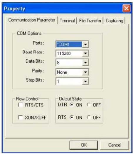
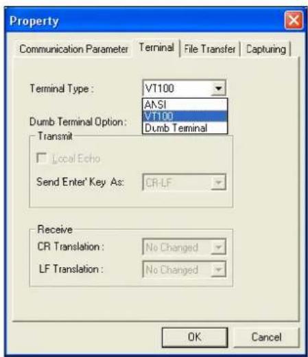
-
Click on the Terminal tab, and select VT100 (or ANSI) for Terminal Type. Click on OK to continue.
-
The Console login screen will appear. Log into the RS-232 console with the login name (default: admin) and password (default: root, if no new password is set).
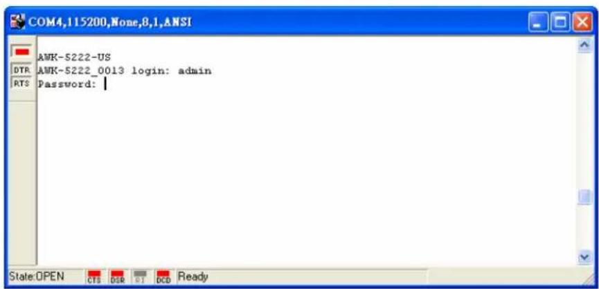
- The AWK-5222's device information and Main Menu will be displayed. Please follow the description on screen and select the administration option you wish to perform.
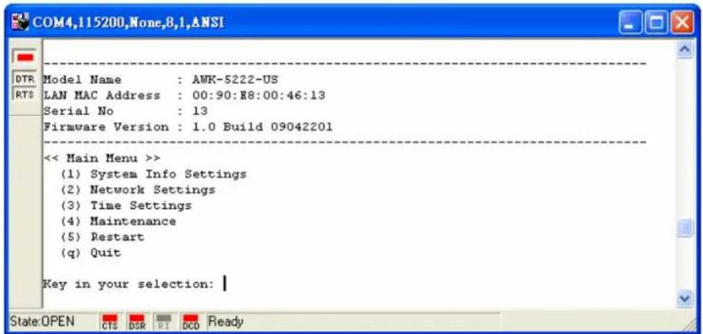

NOTE
To modify the appearance of the PComm Terminal Emulator window, select Edit → Font and then choose the desired formatting options.

ATTENTION
If you unplug the RS-232 cable or trigger DTR, a disconnection event will be evoked to enforce logout for network security. You will need to log in again to resume operation.
Configuration by Telnet and SSH Consoles
You may use Telnet or SSH client to access the AWK-5222 and manage the console over a network. To access the AWK-5222's functions over the network from a PC host that is connected to the same LAN as the AWK-5222, you need to make sure that the PC host and the AWK-5222 are on the same logical subnet. To do this, check your PC host's IP address and subnet mask.

NOTE
The AWK-5222's default IP address is 192.168.127.253 and the default subnet mask is 255.255.255.0 (for a Class C network). If you do not set these values properly, please check the network settings of your PC host and then change the IP address to 192.168.127.xxx and subnet mask to 255.255.255.0.
Follow the steps below to access the console utility via Telnet or SSH client.
- From Windows Desktop, run Start > Run, and then use Telnet to access the AWK-5222's IP address from the Windows Run window. (You may also issue the telnet command from the MS-DOS prompt.)
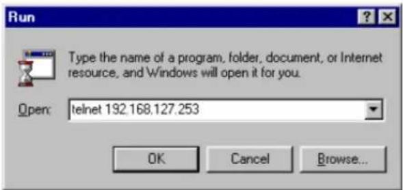
When using SSH client (ex. PuTTY), please run the client program (ex. putty.exe) and then input the AWK-5222's IP address, specifying 22 for the SSH connection port.
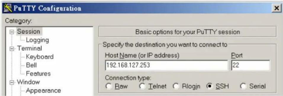
- The Console login screen will appear. Please refer to the previous paragraph "RS-232 Console Configuration" and for login and administration.
Configuration by Web Browser with HTTPS/SSL
To secure your HTTP access, the AWK-5222 supports HTTPS/SSL encryption for all HTTP traffic. Perform the following steps to access the AWK-5222's web browser interface via HTTPS/SSL.
- Open your web browser and type https://

- Warning messages will pop out to warn users that the security certificate was issued by a company they have not chosen to trust.
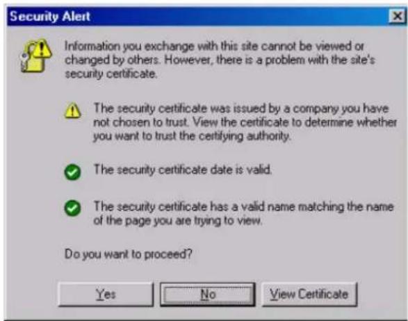
- Select Yes to accept the certificate issued by Moxa IW and then enter the AWK-5222's web browser interface secured via HTTPS/SSL. (You can see the protocol in URL is https.) Then you can use the menu tree on the left side of the window to open the function pages to access each of AWK-5222's functions.
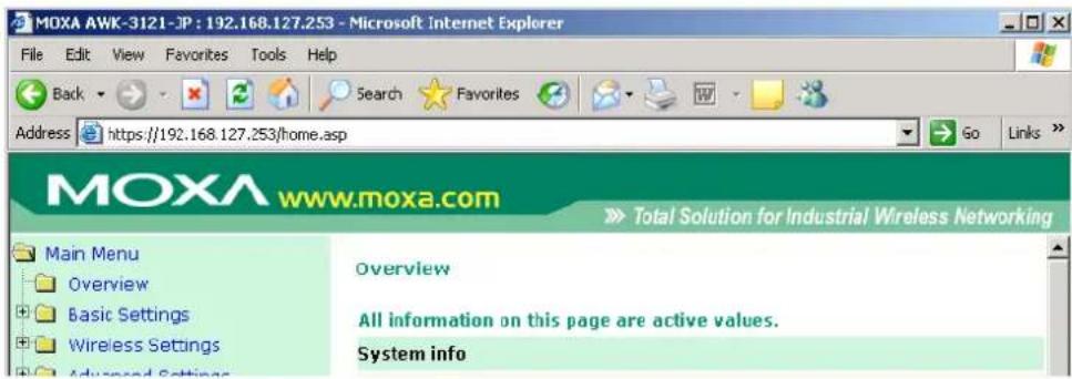
Disabling Telnet and Browser Access
If you are connecting the AWK-5222 to a public network but do not intend to use its management functions over the network, then we suggest disabling both Telnet Console and Web Configuration. Please run Maintenance → Console Settings to disable them, as shown in the following figure.
Console Settings
| HTTP console | ○ Enable | ● Disable |
| HTTPS console | ● Enable | ○ Disable |
| Telnet console | ○ Enable | ● Disable |
| SSH console | ● Enable | ○ Disable |
Submit
This chapter provides more detailed information about wireless-related technologies. The information in this chapter can help you administer your AWK-5222s and plan your industrial wireless network better.
The following topics are covered:
□ Beacon
DTIM
Fragment
□ RTS Threshold
□ STP and RSTP
The STP/RSTP Concept
▶ Differences between RSTP and STP
Beacon
A beacon is a packet broadcast by the AP to keep the network synchronized. A beacon includes the wireless LAN service area, the AP address, the Broadcast destination address, a time stamp, Delivery Traffic Indicator Maps (DTIM), and the Traffic Indicator Message (TIM). Beacon Interval indicates the frequency interval of AP.
DTIM
Delivery Traffic Indication Map (DTIM) is contained in beacon frames. It is used to indicate that broadcast and multicast frames buffered by the AP will be delivered shortly. Lower settings result in more efficient networking, while preventing your PC from dropping into power-saving sleep mode. Higher settings allow your PC to enter sleep mode, thus saving power.
Fragment
A lower setting means smaller packets, which will create more packets for each transmission. If you have decreased this value and experience high packet error rates, you can increase it again, but it will likely decrease overall network performance. Only minor modifications of this value are recommended.
RTS Threshold
RTS Threshold (256-2346) – This setting determines how large a packet can be before the Access Point coordinates transmission and reception to ensure efficient communication. This value should remain at its default setting of 2,346. When you encounter inconsistent data flow, only minor modifications are recommended.
STP and RSTP
The STP/RSTP Concept
Spanning Tree Protocol (STP) was designed to help reduce link failures in a network, and provide protection from loops. Networks that have a complicated architecture are prone to broadcast storms caused by unintended loops in the network. The STP protocol is part of the IEEE802.1D standard, 1998 Edition bridge specification.
Rapid Spanning Tree Protocol (RSTP) implements the Spanning Tree Algorithm and Protocol defined by IEEE802.1w-2001 standard. RSTP provides the following benefits:
- The topology of a bridged network will be determined much more quickly compared to STP.
- RSTP is backward compatible with STP, making it relatively easy to deploy. For example:
- Defaults to sending 802.1D-style BPDUs if packets with this format are received.
- STP (802.1D) and RSTP (802.1w) can operate on the LAN ports and WLAN ports (AP and WDS1-WDS8) of the same AWK-5222.
This feature is particularly helpful when the AWK-5222 connects to older equipment, such as legacy switches.
Differences between RSTP and STP
RSTP is similar to STP, but includes additional information in the BPDUs that allow each bridge to confirm that it has taken action to prevent loops from forming when it decides to enable a link to a neighboring bridge. Adjacent bridges connected via point-to-point links will be able to enable a link without waiting to ensure that all other bridges in the network have had time to react to the change. The main benefit of RSTP is that the configuration decision is made locally rather than network-wide, allowing RSTP to carry out automatic configuration and restore a link faster than STP.
This chapter presents additional information about this manual and product. You can also learn how to contact Moxa for technical support.
The following topics are covered:
□ About This User's Manual
☐ DoC (Declaration of Conformity)
▶ Federal Communication Commission Interference Statement
▶ R&TTE Compliance Statement
□ Firmware Recovery
□ Technical Support Contact Information
About This User's Manual
This manual is mainly designed for, but no limited to, the following hardware and firmware for the AWK-5222:
- Hardware Rev: 1.0
- Firmware Ver: 1.0
You are strongly recommended to visit Moxa's website (http://www.moxa.com) and find the latest product datasheet, firmware, QIG (Quick Installation Guide), UM (User's Manual) and related information.

NOTE
You can find out the hardware revision number of AWK-5222 on the side label.
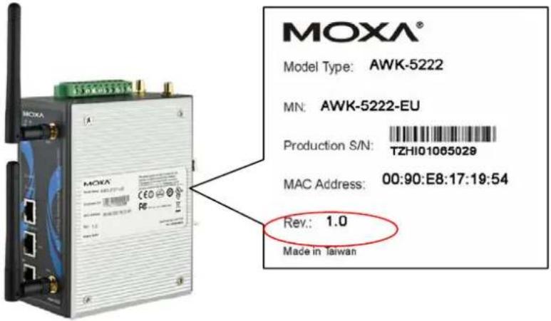
The firmware version number can be seen on the Overview page, as follow:
All information on this page are active values.
System info
| Model name | AWK-5222-US |
| Device name | AWK-5222_0013 |
| Serial No. | 13 |
| System up time | 0 days 06h:02m:04s |
| Firmware version | 1.0 Build 09042201 |
DoC (Declaration of Conformity)
Federal Communication Commission Interference Statement
This equipment has been tested and found to comply with the limits for a Class B digital device, pursuant to Part 15 of the FCC Rules. These limits are designed to provide reasonable protection against harmful interference in a residential installation. This equipment generates, uses and can radiate radio frequency energy and, if not installed and used in accordance with the instructions, may cause harmful interference to radio communications. However, there is no guarantee that interference will not occur in a particular installation. If this equipment does cause harmful interference to radio or television reception, which can be determined by turning the equipment off and on, the user is encouraged to try to correct the interference by one of the following measures:
• Reorient or relocate the receiving antenna.
- Increase the separation between the equipment and receiver.
- Connect the equipment into an outlet on a circuit different from that to which the receiver is connected.
- Consult the dealer or an experienced radio/TV technician for help.
FCC Caution: To assure continued compliance, (example – use only shielded interface cables when connecting to computer or peripheral devices). Any changes or modifications not expressly approved by the party responsible for compliance could void the user's authority to operate this equipment. This transmitter must not be co-located or operated in conjunction with any other antenna or transmitter.
FCC Radiation Exposure Statement
This equipment complies with FCC radiation exposure limits set forth for an uncontrolled environment. This equipment should be installed and operated with a minimum distance of 20 cm between the radiator & your body.
This device complies with Part 15 of the FCC Rules. Operation is subject to the following two conditions: (1) This device may not cause harmful interference, and (2) this device must accept any interference received, including interference that may cause undesired operation.
FCC 15.407(e): Within the 5.15-5.25 GHz band, U-NII devices will be restricted to indoor operations to reduce any potential for harmful interference to co-channel MSS operations.
R&TTE Compliance Statement
This equipment complies with all the requirements of DIRECTIVE 1999/5/CE OF THE EUROPEAN PARLIAMENT AND THE COUNCIL OF 9 March 1999 on radio equipment and telecommunication terminal equipment and the mutual recognition of their conformity (R&TTE).
The R&TTE Directive repeals and replaces in the directive 98/13/EEC (Telecommunications Terminal Equipment and Satellite Earth Station Equipment) as of April 8, 2000.
Safety
This equipment is designed with the utmost care for the safety of those who install and use it. However, special attention must be paid to the dangers of electric shock and static electricity when working with electrical equipment. All guidelines of this and of the computer manufacturer must therefore be allowed at all times to ensure the safe use of the equipment.
EU Countries Intended for Use
The ETSI version of this device is intended for home and office use in Austria, Belgium, Denmark, Finland, France (with Frequency channel restrictions), Germany, Greece, Ireland, Italy, Luxembourg, Portugal, Spain, Sweden, The Netherlands, and United Kingdom.
The ETSI version of this device is also authorized for use in EFTA member states Norway and Switzerland.
EU Countries Not Intended for Use
None.
Potential Restrictive Use
France: only channels 10, 11, 12, and 13.
CE Warning
This is a class B product. In a domestic environment this product may cause radio interference in which case the user may be required to take adequate measures.
Firmware Recovery
When the LEDs of FAULT, and STATE all light up simultaneously and blink at one-second interval, it means the system booting has failed. It may result from some wrong operation or uncontrollable issues, such as an unexpected shutdown during firmware update. The AWK-5222 is designed to help administrators recover such damage and resume system operation rapidly. You can refer to the following instructions to recover the firmware:
Connect to the AWK-5222's RS-232 console with 115200bps and N-8-1. You will see the following message shown on the terminal emulator every one second.
Press Ctrl-C to enter Firmware Recovery Process.....
Press Ctrl-C to enter Firmware Recovery Process.....
Press Ctrl-C to enter Firmware Recovery Process.....
Press Ctrl-C to enter Firmware Recovery Process.....
Press Ctrl-C to enter Firmware Recovery Process.....
Press Ctrl-C to enter Firmware Recovery Process.....
Press Ctrl-C to enter Firmware Recovery Process.....
Press Ctrl-C to enter Firmware Recovery Process.....
Press Ctrl-C to enter Firmware Recovery Process.....
Press Ctrl-C to enter Firmware Recovery Process....
Press Ctrl - C and the following message will appear.
Press Ctrl-C to enter Firmware Recovery Process.....
Press Ctrl-C to enter Firmware Recovery Process.....
IP address of AWK-5222 : 192.168.40.155
Netmask of AWK-5222 : 255.255.252.0
Gateway of AWK-5222 : 192.168.43.254
IP address of TFTP server : 192.168.40.142
1. Start to firmware upgrade using the above network setting immediately.
2. Change the network settings.
Enter your selection: (1-2, enter for abort):
Enter 2 to change the network setting. Specify where the AWK-5222's firmware file on the TFTP server and press y to write the settings into flash memory.
1. Start to firmware upgrade using the above network setting immediately.
2. Change the network settings.
Enter your selection: (1-2, enter for abort): 2
IP address of AWK-5222 : 192.168.1.2
IP address of TFTP server : 192.168.1.1
Netmask of AWK-5222 : 255.255.252.0
Gateway of AWK-5222 : 192.168.1.254
Update RedBoot non-volatile configuration - continue (y/n)? y
AWK-5222 restarts, and the “Press Ctrl-C to enter Firmware Recovery Process…” message will reappear. Press Ctrl-C to enter the menu and select 1 to start the firmware upgrade process.
Press Ctrl-C to enter Firmware Recovery Process.....
IP address of AWK-5222 : 192.168.1.2
Netmask of AMK-5222 : 255.255.252.0
Gateway of AMK-5222 : 192.168.40.142
IP address of TFTP server : 255.255.252.0
1. Start to firmware upgrade using the above network setting immediately.
2. Change the network settings.
Enter your selection : (1-2, enter for abort): 1
Select 0 in the sub-menu to load the firmware image via LAN, and then enter the file name of the firmware to start the firmware recovery.
Load method select :
0. Load from LAN
1. Load from serial with Xmodem
q. Abort
Please select item : 0
Please input file name.
Default file name : AUK-5222.rom
User Input file name : AMK-5222_1.0.rom
Technical Support Contact Information
Customer satisfaction is our number one concern, and to ensure that customers receive the full benefit of our products, Moxa Internet Services has been set up to provide technical support, driver updates, product information, certification status, installation guide and user's manual updates.
The following services are provided:
• E-mail for technical support:
support@moxa.com (Worldwide)
support@usa.moxa.com (The Americas)
• World Wide Web (WWW) Site for product information:
http://www.moxa.com
- Moxa AirWorks AWK-5222
- User's Manual
- Moxa AirWorks AWK-5222 User's Manual
- Copyright Notice
- Trademarks
- Disclaimer
- Technical Support Contact Information www.moxa.com/support
- Chapter 1 Introduction....1-1
- Chapter 2 Getting Started....2-1
- Chapter 3 Web Console Configuration....3-1
- Chapter 4 Software Installation/Configuration ....4-1
- Chapter 5 Other Console Configurations....5-1
- Chapter 6 References....6-1
- Chapter 7 Supporting Information....7-1
- Overview
- Package Checklist
- NOTE
- Product Features
- Product Specifications
- WLAN
- Protocol
- Interface
- Power
- Mechanical
- Environment
- Regulatory Approvals\*
- ATTENTION
- Functional Design
- LED Indicators
- Beeper
- Reset Button
- Relay (Digital Output)
- Antenna
- First-time Installation and Configuration
- Step 4: Use the web-based manager to configure AWK-5222
- Step 5: Select the operation mode for the AWK-5222.
- Step 6: Test communications.
- Communication Testing
- Testing Method for one AWK-5222
- Testing Method for two or more AWK-5222s
- Function Guiding Map
- Configuration by Web Browser
- Basic Settings
- System Info Settings
- Network Settings
- Time Settings
- Wireless Settings
- Operation Mode
- Wireless Redundancy
- Wireless Bridge
- AP-Client
- WLAN1/WLAN2
- Enabling Non-Redundant (Single RF) AP
- Wireless Redundancy mode's Redundant AP
- Wireless Bridge Mode's Master
- Basic Wireless Setting
- WLAN Security Settings
- Open
- WEP
- WPA/WPA2-Personal
- WPA/WPA2-Enterprise (for Redundant AP, AP, or Master mode)
- WPA/WPA2-Enterprise (for Redundant Client, Client, or Slave mode)
- WLAN 1 WLAN Security Settings
- EAP-TLS
- EAP-TTLS
- PEAP
- Advanced Wireless Settings
- Current status
- Step 1:
- Step 2:
- Advanced Settings
- DHCP Server (for AP-Client operation mode's AP mode only)
- Packet Filters
- MAC Filter
- IP Protocol Filter
- TCP/UDP Port Filter
- RSTP Settings (for Master or Slave mode only)
- RSTP status
- Port Status
- SNMP Agent
- Private Key
- Private MIB Information Device Object ID
- Storm Protection
- Auto Warning Settings
- System Log
- System Log Event Types
- Syslog
- Syslog Event Types
- Syslog Server Settings
- E-mail Event Types
- E-mail Server Settings
- Relay
- Relay Event Types
- Trap
- Trap Event Types
- SNMP Trap Receiver Settings
- Status
- Wireless Status
- Associated Client List (for Redundant AP, AP, or Master mode only)
- DHCP Client List (for AP mode only)
- Relay Status
- DI and Power Status
- Maintenance
- Console Settings
- Ping
- Firmware Upgrade
- Config Import Export
- Load Factory Default
- Password
- Misc. Settings
- Save Configuration
- Restart
- Logout
- AWK Search Utility
- Installing AWK Search Utility
- Configuring AWK Search Utility
- Search
- Connection
- Misc.
- RS-232 Console Configuration (115200, None, 8, 1, VT100)
- Configuration by Telnet and SSH Consoles
- Configuration by Web Browser with HTTPS/SSL
- Disabling Telnet and Browser Access
- Beacon
- DTIM
- Fragment
- RTS Threshold
- STP and RSTP
- The STP/RSTP Concept
- Differences between RSTP and STP
- About This User's Manual
- DoC (Declaration of Conformity)
- Federal Communication Commission Interference Statement
- FCC Radiation Exposure Statement
- R&TTE Compliance Statement
- Safety
- EU Countries Intended for Use
- EU Countries Not Intended for Use
- Potential Restrictive Use
- CE Warning
- Firmware Recovery
- Technical Support Contact Information
Brand : Moxa
Model : AWK-5222
Category : Access Point