HM-RC-19 - Thermostat EQ-3 - Free user manual and instructions
Find the device manual for free HM-RC-19 EQ-3 in PDF.

| Product Type | Radio Thermostat |
| Brand | eQ-3 |
| Model | HM-RC-19 |
| Dimensions (approx.) | 80 x 80 x 30 mm |
| Weight (approx.) | 100 g (without batteries) |
| Power Supply | 2 x AA batteries (1.5 V) |
| Radio Frequency | 868.3 MHz (HomeMatic) |
| Range (free field) | Up to 100 m |
| Display | LCD with backlight |
| Temperature Setting Range | 5°C to 30°C |
| Switching Output | Relay, potential-free |
| Switching Voltage | Up to 230 V AC |
| Switching Current | Max. 10 A |
| Protection Class | II |
| Degree of Protection | IP20 |
| Operating Temperature | 0°C to +50°C |
| Main Functions | Heating control, temperature regulation, programming (time/date), manual override, radio communication with HomeMatic central unit |
| Mounting | Wall-mounted (included base and screws) |
| Maintenance | Clean with dry cloth; avoid moisture; replace batteries when low |
| Safety | Only use specified batteries; do not expose to extreme conditions; professional installation recommended for mains connection |
| Spare Parts | User replaceable batteries (AA); additional mounting accessories available |
| Repairability | Limited due to integrated electronics; refer to qualified technician |
Frequently Asked Questions - HM-RC-19 EQ-3
User questions about HM-RC-19 EQ-3
0 question about this device. Answer the ones you know or ask your own.
Ask a new question about this device
Download the instructions for your Thermostat in PDF format for free! Find your manual HM-RC-19 - EQ-3 and take your electronic device back in hand. On this page are published all the documents necessary for the use of your device. HM-RC-19 by EQ-3.
USER MANUAL HM-RC-19 EQ-3
text_image
HomeMatic
Bedienungsanleitung
Funk-Fernbedienung 19 Tasten HM-RC-19, HM-RC-19-B
Seite 4 - 21

Operating Manual
Radio remote control 19 button HM-RC-19, HM-RC-19-B
Page 22 - 39
Printed in Hong Kong
- English edition 12/2007
Documentation © 2007 eQ-3 Ltd., Hong KongAll rights reserved.
No parts of this manual may be reproduced or processed in any form using electronic, mechanical or chemical processes in part or in full without the prior explicit written permission of the publisher.
It is quite possible that this manual has printing errors or defects.
The details provided in this manual are checked regularly and corrections are done in the next edition. We do not assume any liability for technical or printing errors.
All registered trade marks and copyrights are acknowledged.
Printed in Hong Kong
We reserve the right to make changes due to technical advancements without prior notice.
74775 / V 1.0
Inhaltsverzeichnis
text_image
B A C D E F GA – Bedientasten (Tastenpaare)
B - Geräte-LED
natural_image
Simple diagram showing a rectangular box with a circular hole and an arrow pointing right inside a rectangular box (no text or symbols)natural_image
Pure technical line drawing of a door panel with no text or symbolsnatural_image
Technical line drawing of a device casing with internal components and dimension annotations (no text or symbols)natural_image
Pure mechanical assembly diagram showing two rotating components with arrows indicating motion (no text or symbols)1 Information concerning these instructions....23
2 Hazard information 23
3 Your radio remote control does this ....23
4 General system information on HomeMatic....25
5 General information on radio operation .....25
6 Start up....26
6.1 Installing and changing rechargeable batteries.....26
6.1.1 Installing rechargeable batteries....26
6.1.2 Changing rechargeable batteries .....26
6.1.3 Behavior after inserting the rechargeable battery .....27
6.2 Teaching....28
7 Operation....30
7.1 Simple operating functions....30
7.2 Device LED feedback .....31
7.3 Displays on the device display .....32
8 Resetting to factory status ....33
9 Changing the label cards....34
10 Error messages ....35
10.1 Device LED....35
10.1.1 Low rechargeable battery .....35
10.1.2 Command not confirmed....36
10.2 Error messages on the device display .....36
11 Maintenance and cleaning ....37
12 Technical specifications ....38
1 Information concerning these instructions
Read these instructions carefully before beginning operation with your HomeMatic components.
Keep the instructions handy for later consultation! Please hand-over the operating manual as well when you hand-over the device to other persons for use.
Symbols used:
Attention! This indicates a hazard.

Note. This section contains additional important information!
2 Hazard information
Do not open the device. It does not contain any parts to be maintained by the user. In case of a fault, please send the device to our service department.
This device is to be operated indoors only and keep away from the influences of humidity, dust and sunshine or other radiating heat sources.
3 Your radio remote control does this
Hand transmitters and remote controls are used to control the receivers that they are taught to work with. A single button can be taught to work with one or more components and address them all simultaneously. That means that pressing a single button can execute many different tasks.

text_image
B A C D E F GA – Control buttons (button pairs)
B - Device LED
C – Button for displaying messages
D - Button for displaying Alarm/Service messages
E - Button for requesting data from the Central
F - Teach button
G – Battery cabinet cover
The eight button pairs on the remote control can be taught for any HomeMatic components. The three special buttons located on the side are only functional in combination with the Home-Matic Central.
4 General system information on HomeMatic
This device is a part of the HomeMatic home control system and works with the bidirectional BidCoS® wireless protocol.
All devices are delivered in a standard configuration. The functionality of the device can also be configured with a programming device and software. Further resulting functionality and the additional functions provided in the HomeMatic system combined with other components are described in the separate Configuration Instructions and in the HomeMatic System Manual. All current technical documents and updates are provided under www.HomeMatic.com.
5 General information on radio operation
The radio transmission is on a non-exclusive transmission path which means that there is a possibility of interference occurring. Other interfering sources can be caused by switching operations, electrical motors or defective electrical devices.

The range of transmission within buildings can greatly deviate from open air distances. Besides the transmitting power and the reception characteristics of the receiver, environmental influences such as humidity in the vicinity and local structures also play an important role.
Hereby eQ-3 Entwicklung GmbH, declares that this device conforms with the essential requirements and other relevant regulations of Directive 1999/5/EC. The full declaration of conformity is provided under www.HomeMatic.com.
6 Start up
6.1 Installing and changing rechargeable batteries
6.1.1 Installing the rechargeable batteries

natural_image
Simple diagram showing a rectangle with circular holes and an arrow pointing right inside a rectangular box (no text or symbols)Open the rear battery compartment by pushing the battery cover in the direction of the arrow. Insert the three NiMH rechargeable batteries (Type HR 03) that are supplied and make sure that the polarity matches that of the markings in the battery compartment. Close the battery compartment by putting the battery compartment cover back on and pushing it in the opposite direction of the arrow until the cover clicks into place.
6.1.2 Changing rechargeable batteries
Caution! Danger of explosion if rechargeable battery is replaced improperly.

Do not throw the rechargeable batteries in the fire!
Do not short-circuit the rechargeable batteries!
Used batteries are not to be disposed of with the house-hold waste! Please dispose them at your local battery collection point!
Rechargeable batteries are subject to an aging process. They can be recharged several times without any noticeable drop in
capacity. If the rechargeable battery life should be decreased by one or two days for normal remote control usage or if the charge battery indicator is shown again even after charging, the rechargeable batteries must be replaced with new rechargeable batteries of the same type Micro NiMH (HR 03, capacity of at least 1000mAh). Following the instructions in the previous chapter in this case.
6.1.3 Behavior after inserting charged batteries
Rechargeable batteries that have been charged in an external charger can also be inserted. After inserting the rechargeable battery, the remote control will run a self-test. This runs for approx. 2 seconds. The initialization runs next. The completion is indicated with the LED test display: red, green, orange, each for a half second. If an error occurs, it is indicated with red flashing!
| One long flash, two short flashes, pause (repeated twice) | Battery power too low |
| One long flash, one short flash, pause (infinite) | Remote control defective |
If the battery power is low, as long as the power level allows, the button actuation is activated and the remote control is ready for operation. Depending on the requirements, the battery may recover and send again many times after a short break. If the power drops too low when sending, the respective error code is displayed. The symbol for low battery is shown on the display of the remote control.

If the behavior of the remote control is undefined, put the remote control in the charger. The remote control is then supplied through the charging station and should indicate normal behavior. Charge the rechargeable batteries of the remote control for a longer period of time in such cases.

The charge status display on the remote control display only shows the correct charge status if the rechargeable batteries in the remote control have been completely charged in the charging station one time. If rechargeable batteries have been charged elsewhere and are then inserted in the remote control, the status indicator indicates low batteries. This effect disappears if the remote control has been completely charged in the charging station one time.
6.2 Teaching
Please read this section completely before starting with any teaching!
The remote control supports three different modes
• Operation mode (normal operation)
- Configuration mode (for changing remote control parameters)
- Teach mode (Teaching HomeMatic components)
Training requires that both devices to be connected are put into teach mode and the desired channel is selected for training.

You can teach the eight button pairs of the remote control directly on the HomeMatic actuators. The three special buttons located on the side are only functional in combination with the HomeMatic Central.
The teach button is on the back of the hand transmitter at the right over the battery compartment cover. This button is located within a recess in the housing so that it cannot be pressed accidentally.

natural_image
Pure technical line drawing of a door panel with no text or symbolsTo actuate teach mode on the remote control, press the teach button with a pointed object. The remote control is then in configuration mode, indicated by the device LED flashing in green.
"CONFIG" is shown in the device display. (If you want to leave the configuration mode, briefly press the teach button again.) Press the operating button that you want to teach to enter teach mode. The device LED flashes orange. "LEARN" is shown in the device display. (Abort with a short press of the teach button, the device LED will then illuminate in red.)
If no teaching occurs, teach mode is automatically ended after 20 seconds. If other devices are in teach mode, these are taught.
If learning is completed successfully, it is indicated with the flashing green LED (length of time depends on whether it is still configuring).

Note: If the remote control is already taught for a center and therefore is blocked for direct training, it can still be put in teach mode as described above, the device LED is illuminated in red for 2 seconds after pressing an operating button however. Direct teaching is not possible!
| Min. 2 sec. green LED Teaching successful | |
| 2 sec red LED | Teaching failed |
| Orange flashing | Only remote control in Teach mode |
| Remote control in configuration mode and illuminated red with button actuation | Remote control already taught for center and is therefore blocked from direct teaching |
7 Operation
7.1 Simple operating functions
After teaching, simple operating functions are available.
The 16 buttons on the remote control are taught as eight separate button pairs (ON/OFF) for one receiver upon delivery, depending on from which pair the button was pressed for teaching. Switch actuators and dimmers can then be switched ON/OFF or dimming occurs by holding the button pressed. The blind actuators move up or down. The three special buttons located on the side of the remote control are only functional in combination with the HomeMatic Central.
The remote control is equipped with a vibration sensor. The background lighting of the button field is illuminated for 5
seconds when the remote is shocked or if a button is pressed. The time is extended by 5 seconds each time a shock is registered or a button is pressed while the background is illuminated.

Do not carry the remote control in a pocket or laying in your vehicle. Accidentally switching the background lighting on consumes power and reduces the time
between charging batteries!
7.2 Device LED feedback
The feedback signals apply for operation with and without the center.
No actuators have been taught yet:
Brief press of the button: LED is illuminated in orange for 1 second,
Extended button press: LED is illuminated in orange for 1 second, Button held down: LED is illuminated as long as the button is pressed and goes dark afterward.
Actuators are taught:
Brief/long press of the button: LED is illuminated in orange as long as the function transfer requires, this time depends on the number of actuators that have been taught for this button, the number of required transmission attempts and the encoding and transmission mode. After the radio transmission is complete, the LED is illuminated in either red or green for 1 second.
Green: all actuators have confirmed the (last) bi-directional command,
Red: at least one actuator has confirmed the (last) bi-directional command.
Button held down: LED is illuminated in orange as long as the button is held down and behaves as above afterward Button held down (receiver with burst transmission mode): Orange as long as transmitting, then feedback indicated with 1 second in red or
green when held pressed.
Remote control in special mode:
LED flashes slowly in green: Configuration mode (waiting for radio signal),
LED flashes quickly in green: Configuration mode is active and data is being received.
LED flashes slowly in orange: Teach mode (waiting for radio signal),
LED flashes slowly in red: Preparatory stage for resetting to factory defaults (waiting for long button press on the teach button for resetting, or brief button press for aborting).
7.3 Displays on the device display
The remote control has 16 buttons which can be assigned as you wish for teaching (adding) the various actuators. The display shows values supported by one or more symbols depending on the type of actuator added.
Dim:
bulb, Arrow up/down, %, % value (hour glass in cases)
General switching:
Switch symbol, ON/OFF
Winmatic:
Window symbol, Arrow up/down, %, % value, OPEN/CLOSE (hourglass in cases)
Keymatic:
Door symbol, "OPEN/CLOSE", (hourglass in cases)
Marquee-/roll shutter-/door control:
Roll shutter symbol, Arrow up/down, %, % value, (hourglass in cases)
More than one actuator taught on a button: Scene symbol, hourglass, "OK"
The hourglass indicates that a command or a command sequence is still being processed and feedback is awaited. The arrows in the display show a direction of movement or the direction for a value change: Open/Close, Increase/Decrease.
The display switches into dormant state after 30 seconds of being inactive and "HM" is shown on the display as is configured in the factory.
The messages on the display are in English (German) as default. The display language can be chosen through the Central however.
8 Resetting to factory status
Hold the teach button down for at least 5 seconds. The device LED starts to flash slowly in red. (If you want to abort the reset procedure at this time, you can press the teach button briefly again or wait 15 seconds. In either case, the flashing red will stop.)
To reset the device, press the teach button again for at least 5 seconds. The LED now starts to flash in red faster while holding the button down and "RESET" is shown on the display. Releasing the button completes the reset procedure and the LED is illuminated for approx. 3 seconds to confirm the reset operation.
Possible error messages:
(This error can occur now if you have a Central and have taught the device for this Central.)
If the LED does not start flashing after holding the button down for 5 seconds but is illuminated continuously, the device cannot be reset! In this case, the encoding is active using a system security key that differs from the key delivered with the system.
In order to reset the device, you must use the configuration software of the center for resetting! The procedure is described in the center software instructions.
9 Changing the label cards
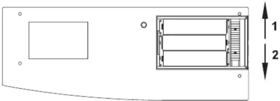
natural_image
Technical diagram of a device casing with internal components and dimension annotations (no text or symbols)First, open the battery compartment cover as described for changing batteries. A red slider switch is located under the batteries. Push the slider switch in direction 2.

text_image
Push the slide switch in direction 21Set the remote control down on the table in front of you with the buttons facing up. Flip the button cover up and pull the cover out of the device at an angle.
The lighting sheet can be accessed between the buttons now. A diffuser sheet is already mounted on it and ensures even illumination and should therefore not be removed.
Numerous labels for various applications are provided on the enclosed sheet. Choose the desired labels and separate them carefully from the sheet using the perforations provided.

natural_image
Pure mechanical assembly diagram showing two curved arrows indicating motion or force direction (no text or symbols)Slip the label card into the slot on one side next to the button to be labeled then. Bow the label card upward slightly to push it through to the opposite side in the slot. The label card should now lay flat on the lighting sheet. Repeat the process for all other label cards.
Finally, set the keypad cover back in place on the remote control and latch it with the slider switch in the battery cabinet. Insert the batteries again and close the battery compartment.
If no suitable label exists on the card provided, use the sheet of unprinted labels. These labels can be printed with a standard printer.
Templates can be downloaded under www.HomeMatic.com.
10 Error messages
10.1 Device LED
10.1.1 Low rechargeable battery
If the rechargeable batteries are too weak, the respective error code (see section "Installing and changing rechargeable batteries") is shown.
If the batteries are so weak that a reset is triggered several times in a row without transmitting successfully, no transmission will be made for following button presses and the LED will only be illuminated in red for 0.5 seconds.
10.1.2 Command not confirmed
If a receiver does not confirm a command (at least one when more than one have been taught), the device LED is illuminated in red when the transmission is complete. The error will then be found with the receiver:
- Receiver not accessible
- Receiver cannot execute command (load failure, mechanical blockage, etc.)
• Defective receiver
In addition to the feedback message on the device LED, the feedback message on the device display also enables a more exact analysis of the error that occurred.
10.2 Error messages on the device display
There are two types of error messages:
Communication error
Actuator could not execute the command
If a communication error occurs, the message "CO-ER" and the antenna symbol appear on the display. The transmit LED is illuminated in red for a short period!
If the receiver confirms an incoming radio telegram, but the command cannot be executed because of an error on the actuator side, "FAIL" appears on the remote control display (Transmit LED is illuminated in green).
If the receiver confirms the receipt of the radio command but cannot execute it (because a block is set, etc.) and indicates this on the remote control, "NAK" is shown on the display.
For a scene call, a communication error with a participant can be indicated with the message "CO-ER" (+ red transmit LED). If the command cannot be executed by at least one participant even through the telegram has been received, "FAIL" is shown on the
display (Transmit LED is illuminated in green).
If two errors of different types occur, the communication error is categorized and indicated as severe.
11 Maintenance and cleaning
The product is maintenance-free besides possibly requiring a battery change. Maintenance or repairs are only to be done by trained professionals. Clean the product using a soft, clean, dry and lint-free cloth.
To remote heavier contamination, make the cloth damp with lukewarm water. Cleaning agents that contain solvents are not to be used because it can harm the plastic housing and the labels.
12 Technical specifications
Remote control:
Radio frequency: 868.3 MHz
Typ. outdoor range: 200 m
Power supply: 3x HR03 (Micro)
Protection type: IP20
Housing: ABS
Housing colors: Pure white with silver faceplate,
Graphite black with black faceplate
Dimensions: 167 x 63 x 19 mm
(H x W x D, without key-chain)
Weight: 90 g (without rechargeable batteries)
Charger:
Power supply: Plug-in mains adapter 7.5V DC
Protection type: IP20
Housing: ABS
Housing colors: Pure white with silver faceplate,
Graphite black with black faceplate
Dimensions: 36 x 108 x 72 mm
(H x W x D, without key-chain)
Weight: 30 g (without power supply)
Subject to technical changes.

Instructions for disposal:
Do not dispose off the device as part of household garbage!
Electronic devices are to be disposed of in accordance with the guidelines concerning electrical and electronic devices
via the local collecting point for old electronic devices.

The CE sign is a free trade sign addressed exclusively to the authorities and does not include any warranty of any properties.

text_image
eQ3eQ-3 AG
Maiburger Straße 29
D-26789 Leer
www.eQ-3.com