
Open Hybrid MEM - Chauffe-eau et chaudière SIME - Free user manual and instructions
Find the device manual for free Open Hybrid MEM SIME in PDF.


| Product Type | Wall-mounted gas condensing combi boiler |
| Brand | SIME |
| Model | Open Hybrid MEM |
| Energy Source | Natural gas / LPG |
| Heating Output (Max) | 24 kW |
| Domestic Hot Water Output (Max) | 30 kW |
| DHW Flow Rate (Δt 25°C) | 12.9 l/min |
| Efficiency Class (Heating) | A (ErP) |
| Efficiency Class (Hot Water) | A |
| Dimensions (H x W x D) | 700 x 400 x 300 mm |
| Weight | 35 kg |
| Power Supply | 230 V / 50 Hz |
| Electrical Power Consumption | 120 W |
| Modulation Ratio | 1:10 |
| Ignition | Electronic |
| Expansion Vessel Capacity | 8 L |
| Max Water Pressure | 3 bar |
| Min Water Pressure | 0.5 bar |
| Flue Type | Room sealed (C13, C33) |
| NOx Class | 5 |
| Maintenance | Annual service recommended |
| Safety Features | Frost protection, anti-blocking pump, safety thermostat |
| Spare Parts Availability | Available from authorized SIME dealers |
Frequently Asked Questions - Open Hybrid MEM SIME
User questions about Open Hybrid MEM SIME
0 question about this device. Answer the ones you know or ask your own.
Ask a new question about this device
Download the instructions for your Chauffe-eau et chaudière in PDF format for free! Find your manual Open Hybrid MEM - SIME and take your electronic device back in hand. On this page are published all the documents necessary for the use of your device. Open Hybrid MEM by SIME.
USER MANUAL Open Hybrid MEM SIME
User Instructions (ENG)
Dispay impianto
MAIN INFORMATION....20
Responsibility
Terms and definitions
Identification and method to request assistance
TECHNICAL INFORMATION 21
Main components description
INFORMATION REGARDING ADJUSTMENTS....22
User instructions
INFORMATION REGARDING ADJUSTMENTS....26
Alarms
Responsibility
| Responsibility of the manufacturer | Our products are manufactured in compliance with the requirements of various applicable European Directives, and are therefore supplied with CE marking and all relative documents.Interest in quality of our products incites us towards constant improvement. We thus reserve the right to change the features specified in this document at any time and without prior notice.As manufacturers, we cannot be held responsible for the following claims:Failure to comply with product installation and user instructions.Failure or inadequate production maintenance. |
| Responsibility of the installer | The installer is responsible for installation operations, which must be carried out to perfection. The installer must comply with the following requirements:Read and comply with the requirements reported in the instructions suppliedwith the product.Set up the system in compliance with the laws in force and national and localstandards and requirements.Notify the user of the compulsory periodic maintenance and checks.Give the user instructions booklet to the user. |
| Responsibility of the user | In order to guarantee perfect system operation, the user must comply with the following requirements:Carefully read and comply with the user instructions supplied with the sys-tem.Refer to qualified operators for installation and commissioning.Qualified technical personnel is to carry out checks and maintenance operations. Incorrect installation and/or inadequate maintenance can damage persons or things.Ask the installer to show you how the system operates.Keep the user instructions in a good condition and next to the equipment forpossible quick reference.This equipment was not designed to be used by persons (including children) having reduced physical, sensory or mental abilities or having no experience or knowledge in this regard. |
Terms and definitions
| DHW | Domestic Hot Water |
| Pdc | Heat pump |
Identification and method to request assistance
| Fonderie Sime S.p.A. |
| Via Garbo, 27 - 37045 Legnago VR |
| Tel. 0442 631111 |
| Fax 0442 631291 |
Main components description
User interface
Only buttons with lit LEDs are enabled.
Keys Functionality

Alarms display (if applicable)
Flashing red light = alarm status

Esc key = Goes back to the previous menu level or main screen

Enter key = Item selection, confirmation

Down arrow key = Scroll forward

Up arrow key = Scroll back
User instructions
Main display
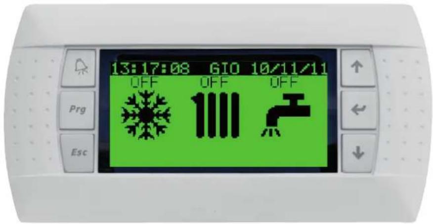
From the STANDBY screen with the SIME logo to access the main screen, press one of the following keys:


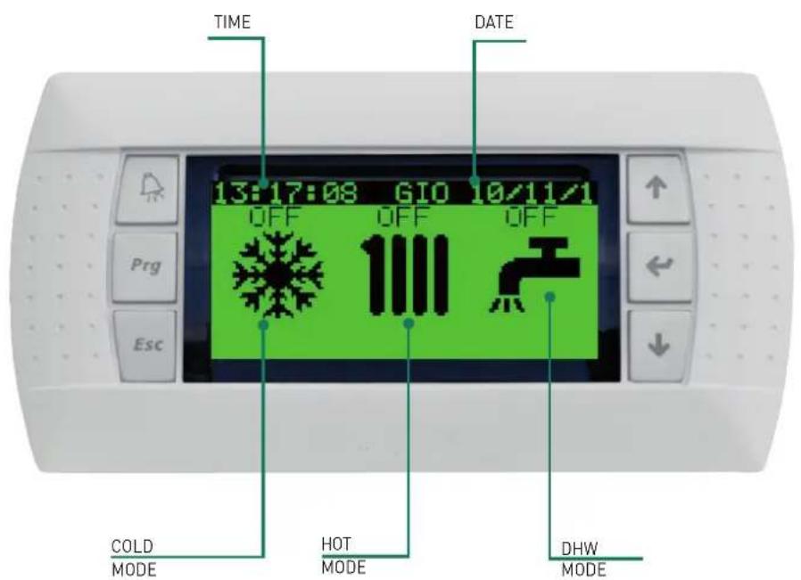
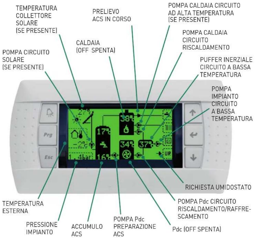
System display
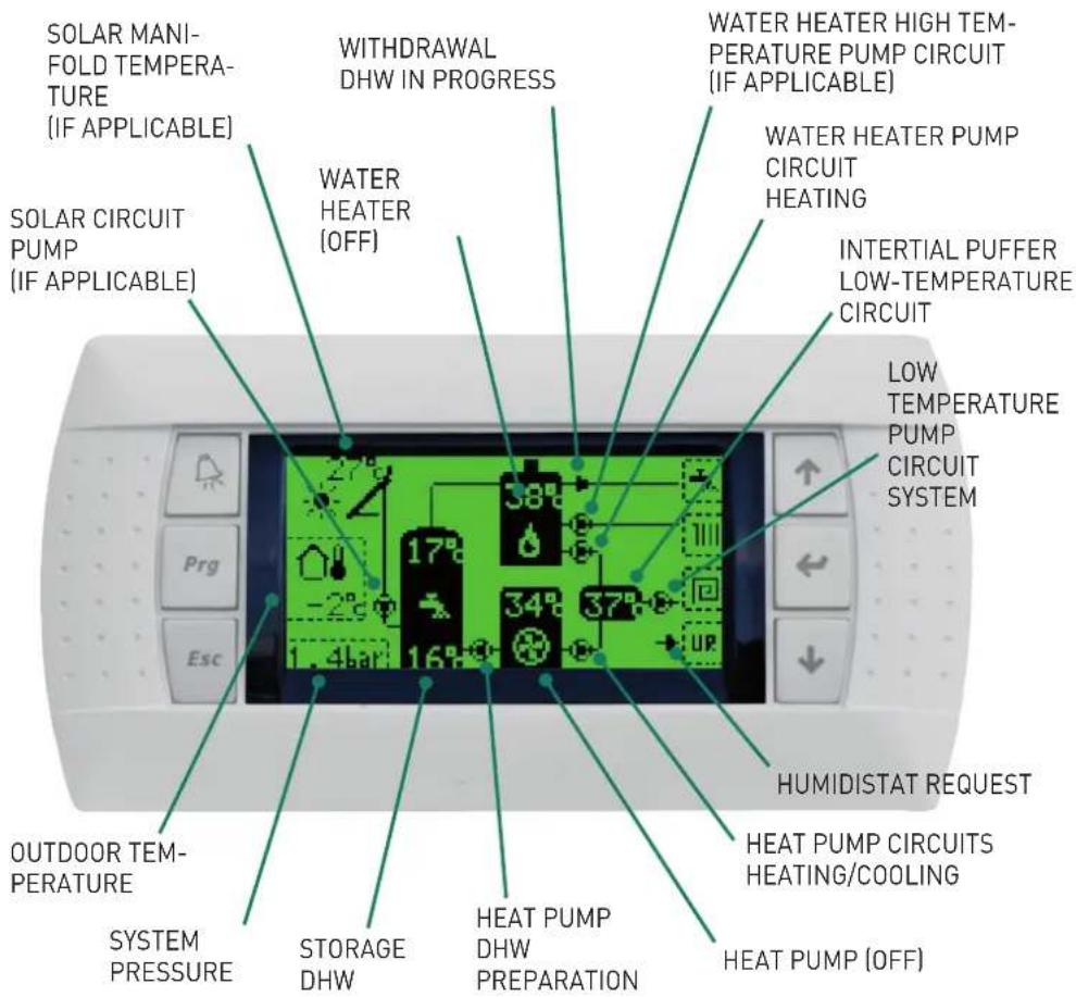
NOTE: The Display only represents the components actually present in the system.
| For each setting |
| From the STANDBY screen with the SIME logo, press one of the following keys ↑ ← ↓ to access the main screenPress • to enterSelect the mode to set using the • and keysPress • to enterSelect using the • and keysPress • to confirm or to exit |
Setting Operating mode air conditioning
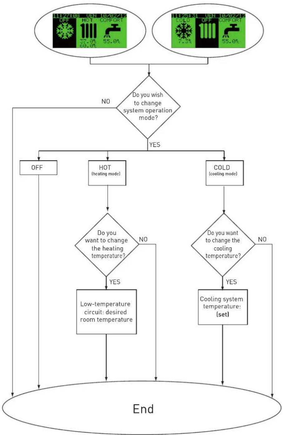
flowchart
graph TD
    A["OFF"] --> B{Do you wish to change system operation mode?}
    B -->|NO| C["End"]
    B -->|YES| D["OFF"]
    E["HOT (heating mode)"] --> F{Do you want to change the heating temperature?}
    F -->|NO| G["Low-temperature circuit: desired room temperature"]
    F -->|YES| H["COLD (cooling mode)"]
    G --> I["End"]
    H --> I
    I --> J["Cooling system temperature: (set)"]
| For each setting |
| From the STANDBY screen with the SIME logo, press one of the following keys ↑ ↔ ↓ to access the main screenPress • to enterSelect the mode to set using the • and keysPress • to enterSelect using the • and keysPress • to confirm or Esc to exit |
DHW Setting
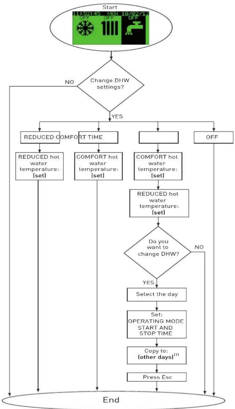
flowchart
graph TD
    A["Start"] --> B{Change DHW settings?}
    B -->|NO| C["REDUCED COMFORT TIME"]
    B -->|YES| D["COMFORT HOT WATER TEMPERATURE: (set)"]
    C --> E["REDUCED HOT WATER TEMPERATURE: (set)"]
    D --> F["COMFORT HOT WATER TEMPERATURE: (set)"]
    E --> G["REDUCED HOT WATER TEMPERATURE: (set)"]
    F --> H["COMFORT HOT WATER TEMPERATURE: (set)"]
    G --> I{Do you want to change DHW?}
    H --> I
    I -->|NO| J["Select the day"]
    I -->|YES| K["Set: OPERATING MODE START AND STOP TIME"]
    J --> L["Set: OPERATING MODE START AND STOP TIME"]
    L --> M["Copy to: (other days)11"]
    M --> N["Press Esc"]
    N --> O["End"]
(1) This function enables you to copy the time programme just set to another day or to all days of the week.
| For each setting |
| From the STANDBY screen with the SIME logo, press one of the following keys ↑ ↔ ↓ to access the main screenPress → to enterSelect the mode to set using the ▲ and keys↓Press → to enterSelect using the ▲ keys↓Press ← to confirm or Esc to exit |
Setting Date and time
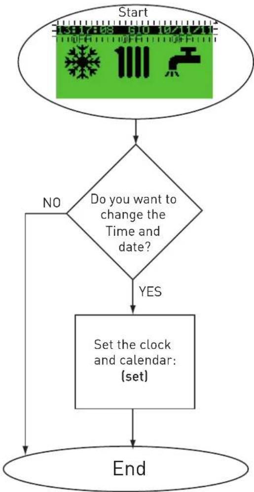
flowchart
graph TD
    A["Start"] --> B{Do you want to change the Time and date?}
    B -->|NO| C["End"]
    B -->|YES| D["Set the clock and calendar: (set)"]
    D --> C
NOTE: The control unit is set to automatically change to summer and winter time.
Alarms
Main display
Alarms are signalled by a flashing red symbol

To display current alarms, press the

key and use the

keys to
scroll.
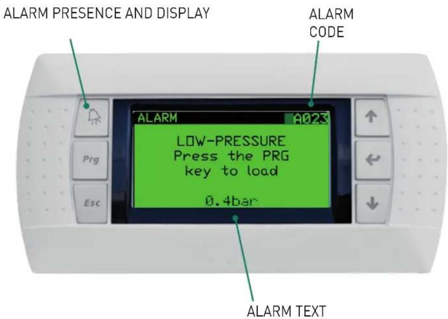
| Alarm Code | Description Solutions | |
| A001 | B1 probe failure alarm | Contact a Sime authorised technical assistance centre. |
| A002 | B2 probe failure alarm | |
| A003 | B3 probe failure alarm | |
| A004 | B4 probe failure alarm | |
| A005 | B5 probe failure alarm | |
| A018 | Solar circuit operation alarm | |
| A020 | Temperature limit accumulation overrun alarm | |
| A021 | System safety thermostat intervention alarm | |
| A023 | System Low-Pressure Alarm | Try to load the system. If the problem persists, contact a Sime authorised technical assistance centre. |
| A024 | System High-Pressure Alarm | Contact a Sime authorised technical assistance centre. |
| A050 | Modbus communication general alarm | |
| A051 | Modbus communication with water heater alarm | |
| A052 | Modbus communication with heat pump alarm | |
| A100 | General water heater alarm | |
| A200 | General heat pump alarm |
sime®
Brand : SIME
Model : Open Hybrid MEM
Category : Chauffe-eau et chaudière