
MIA-30 - Water heaters and boilers SIME - Free user manual and instructions
Find the device manual for free MIA-30 SIME in PDF.


| Product Type | Condensing sealed wall-mounted combi boiler (heating and instant domestic hot water) |
| Model | MIA-30 |
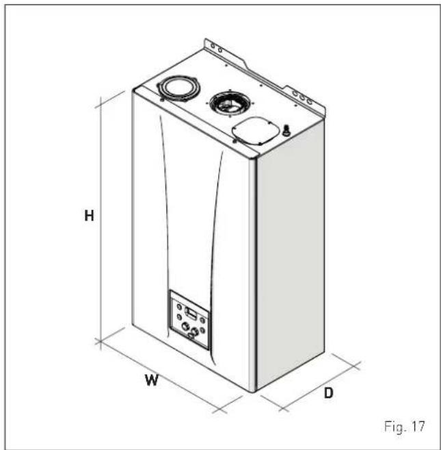
| Dimensions (H x W x D) | 700 x 420 x 262 mm |
| Weight | 27.5 kg |
| Power Supply | 230 V ~ 50 Hz, single phase |
| Maximum Electrical Power Consumption | 86 W (at full load), 4 W standby |
| Fuel Types | Natural gas (G20) and LPG (G31) – convertible via parameter setting |
| Nominal Heat Input | 24 kW (G20/G31) |
| Nominal Heat Output (80-60°C) | 23.6 kW |
| Nominal Heat Output (50-30°C) | 25.6 kW |
| Minimum Heat Output (80-60°C) | 4.6 kW |
| DHW Flow Rate (ΔT 30°C) | 14.2 l/min |
| Continuous DHW Flow Rate (ΔT 25°C / 35°C) | 17.5 / 12.5 l/min |
| Maximum Useful Efficiency (50-30°C) | 106.6% |
| Useful Efficiency at 30% Load (40-30°C) | 108.6% |
| Seasonal Space Heating Energy Efficiency Class | A |
| DHW Energy Efficiency Class | A |
| NOx Class | 6 (< 56 mg/kWh) |
| Safety Devices | Thermal safety thermostat (100°C), 3 bar relief valve, water pressure switch, delivery sensor, DHW sensor, exhaust sensor |
| Control Panel | Heating knob (20-80°C), DHW knob (10-60°C), LCD display, mode selection, reset button |
| Flue Options | Coaxial 60/100 mm or 80/125 mm; separate ducts 80 mm |
| Expansion Vessel Capacity | 7 litres, prefilled at 1.0 bar |
| Maintenance | Annual servicing required (condition of warranty); external cleaning with damp cloth; no abrasive products |
| Spare Parts | Only original Sime spare parts; power cable must be ordered as spare |
| Warranty | 1 year parts and labour (extended if registered and serviced annually) |
| Compliance | Gas Appliance Regulation (EU) 2016/426, Boiler Efficiency Directive 92/42/EEC, Low Voltage Directive 2014/35/EU, EMC Directive 2014/30/EU, Ecodesign Directive 2009/125/EC |
| Benchmark Scheme | Licensed member; commissioning and service records must be completed |
Frequently Asked Questions - MIA-30 SIME
User questions about MIA-30 SIME
0 question about this device. Answer the ones you know or ask your own.
Ask a new question about this device
Download the instructions for your Water heaters and boilers in PDF format for free! Find your manual MIA-30 - SIME and take your electronic device back in hand. On this page are published all the documents necessary for the use of your device. MIA-30 by SIME.
USER MANUAL MIA-30 SIME
Condensing sealed wall-mounted boiler
MIA-30
USER, INSTALLATION AND SERVICING INSTRUCTIONS
natural_image
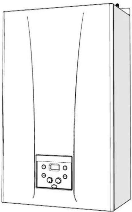
Line drawing of a rectangular appliance with a control panel and buttons (no text or symbols)ENSURE THAT THESE INSTRUCTIONS ARE LEFT FOR THE USER AFTER COMPLETION OF THE BENCHMARK SECTION
PLEASE READ THE IMPORTANT NOTICE WITHIN THIS GUIDE REGARDING YOUR BOILER WARRANTY






To consult the documentation, visit our website www.sime.it
BOILER DETAILS
please position here a sticker from installation pack

IMPORTANT NOTICE
For the first year all of our appliances are protected by our manufacturer's guarantee which covers both parts and labour.
As you would expect from Sime Ltd, it is our aim to provide our valued customers with the best in after sales and service.
To take advantage of any extended warranty offered, all you have to do is to adhere to these 3 simple conditions:
- The installation must be carried out to Manufacturers/Benchmark Standards by a Gas Safe Registered Engineer, and recorded in the installation manual.
• The appliance must be registered with both Sime Ltd and Gas Safe within 30 days of installation. - The appliance must be serviced every 12 months, within 30 days of the anniversary of the installation date, by either Sime Ltd or a Gas Safe registered engineer- ensuring that the Benchmark service record in the installation manual is completed.
Failure to comply with the above will result in only the 12 month warranty being offered. In the absence of any proof of purchase, the 12 month warranty period will commence from the date of manufacture of the boiler as shown on the appliance data plate.
SAFE HANDLING
This boiler may require 2 or more operatives to move it into its installation site, remove it from its packaging and during movement into its installation location. Manoeuvring the boiler may include the use of a sack truck and involve lifting pushing and pulling.
Caution should be exercised during these operations.
Operatives should be knowledgeable in handling techniques when performing these tasks and the following precautions should be considered:
- Grip the boiler at the base
- Be physically capable
- Use personal protective equipment as appropriate e.g. gloves, safety footwear.
During all manoeuvres and handling actions, every attempt should be made to ensure the following unless unavoidable and/or the weight is light.
- Keep back straight
- Avoid twisting at the waist
- Always grip with the palm of the hand
- Keep load as close to the body as possible
- Always use assistance
WARNING
Caution should be exercised when performing any work on this appliance.
Protective gloves and safety glasses are recommended.
- Avoid direct contact with sharp edges.
- Avoid contact with any hot surfaces.
NOTICE
Please be aware that due to the wet testing of the appliance, there may some residual water in the hydraulic circuit.
- Protect any surfaces, carpets or floorings.
- Use a suitable container to catch any water that escape when removing the protective caps from the connections.
All descriptions and illustrations provided in this manual have been carefully prepared but we reserve the right to make changes and improvements in our products that may affect the accuracy of the information contained in this manual.
Code Of Practice
For the installation, commissioning and servicing of domestic heating and hot water products
Benchmark places responsibilities on both manufacturers and installers.* The purpose is to ensure that customers** are provided with the correct equipment for their needs, that it is installed, commissioned and serviced in accordance with the manufacturer's instructions by competent persons and that it meets the requirements of the appropriate Building Regulations. Installers are required to carry out work in accordance with the following:

*The use of the word "installer" is not limited to installation itself and covers those carrying out installation, commissioning and/or servicing of heating and hot water products, or the use of supporting products (such as water treatment or test equipment).
**Customer includes householders, landlords and tenants.
© Heating and Hotwater Industry Council (HHIC)
Standards of Work
- Be competent and qualified to undertake the work required.
• Install, commission, service and use products in accordance with the manufacturer's instructions provided. - Ensure that where there is responsibility for design work, the installation is correctly sized and fit for purpose.
- Meet the requirements of the appropriate Building Regulations. Where this involves notifiable work be a member of a Competent Persons Scheme or confirm that the customer has notified Local Authority Building Control (LABC), prior to work commencing.
- Complete all relevant sections of the Benchmark Checklist/Service Record when carrying out commissioning or servicing of a product or system.
- Ensure that the product or system is left in a safe condition and, whenever possible, in good working order.
- Highlight to the customer any remedial or improvement work identified during the course of commissioning or servicing work.
- Refer to the manufacturer's helpline where assistance is needed.
- Report product faults and concerns to the manufacturer in a timely manner.
Customer Service
- Show the customer any identity card that is relevant to the work being carried out prior to commencement or on request.
- Give a full and clear explanation/demonstration of the product or system and its operation to the customer.
- Hand over the manufacturer's instructions, including the Benchmark Checklist, to the customer on completion of an installation.
- Obtain the customer's signature, on the Benchmark Checklist, to confirm satisfactory demonstration and receipt of manufacturer's instructions.
- Advise the customer that regular product servicing is needed, in line with manufacturers' recommendations, to ensure that safety and efficiency is maintained.
- Respond promptly to calls from a customer following completion of work, providing advice and assistance by phone and, if necessary, visiting the customer.
- Rectify any installation problems at no cost to the customer during the installer's guarantee period.
www.centralheating.co.uk
The Benchmark Scheme
Sime Ltd is a licensed member of the Benchmark Scheme which aims to improve the standards of installation and commissioning of domestic heating and hot water systems in the UK and to encourage regular servicing to optimise safety, efficiency and performance.
Benchmark is managed and promoted by the Heating and Hotwater Industry Council.
For more information visit www.centralheating.co.uk.
Please ensure that the installer has fully completed the Benchmark Checklist in the use and maintenance section of the installation instructions supplied with the product and that you have signed it to say that you have received a full and clear explanation of its operation.
The installer is legally required to complete a commissioning checklist as a means of complying with the appropriate Building Regulations (England and Wales).
All installations must be notified to Local Area Building Control either directly or through a Competent Persons Scheme.
A Building Regulations Compliance Certificate will then be issued to the customer who should, on receipt, write the Notification Number on the Benchmark Checklist.
This product should be serviced regularly to optimise its safety, efficiency and performance.
The service engineer should complete the relevant Service Record on the Benchmark Checklist after each service.
The Benchmark Checklist may be required in the event of any warranty work and as supporting documentation relating to home improvements in the optional documents section of the Home Information Pack.
Important Information
IT IS A STATUTORY REQUIREMENT THAT ALL GAS APPLIANCES ARE INSTALLED BY COMPETENT PERSONS, IN ACCORDANCE WITH THE GAS SAFETY (INSTALLATION AND USE) REGULATIONS (CURRENT EDITION). The manufacturer's instructions must not be taken as overriding any statutory requirements, and failure to comply with these regulations may lead to prosecution.
No modifications to the appliance should be made unless they are fully approved by the manufacturer.
GAS LEAKS: DO NOT OPERATE ANY ELECTRICAL SWITCH, OR USE A NAKED FLAME. TURN OFF THE GAS SUPPLY AND VENTILATE THE AREA BY OPENING DOORS AND WINDOWS CONTACT THE GAS EMERGENCY SERVICE ON 0800111999.

Please refer to commissioning instructions for filling in the checklist at the back of this installation guide.
Note: All Gas Safe registered installers carry a ID Card.
You can check your installer is Gas Safe Registered by calling 0800 408 5577
Please remember to carry out the following checks after installation. This will achieve complete customer satisfaction, and avoid unnecessary service calls. A charge will be made for a service visit where the fault is not due to a manufacturing defect.
- Has a correct by-pass been fitted and adjusted?
- Has the system and boiler been flushed?
- Is the system and boiler full of water, and the correct pressure showing on the pressure gauge?
- Is the Auto Air Vent open?
- Has the pump been rotated manually?
- Is the gas supply working pressure correct?
- Is the boiler wired correctly? (See installation manual).
- Has the D.H.W. flow rate been set to the customer requirements?
- Has the customer been fully advised on the correct use of the boiler, system and controls?
- Has the Benchmark Checklist in the use and maintenance section of this manual, been completed?
Dear Customer,
Thank you for purchasing a Sime Ltd MIA-30 boiler, a new-generation modulating condensing device with technical features and excellent performance, allowing you to satisfy your heating and instant domestic hot water requirements with the utmost safety and limited running costs.
RANGE
| MODEL CODE | GAS COUNCIL NUMBER | |
| MIA-30 8116647 GC No 47-283-90 | ||
NOTE: Some models may NOT be available in some countries.
COMPLIANCE
Our company declares that MIA-30 boilers comply with the following directives:
– Gas Appliances EU Regulation 2016/426
- Boiler Efficiency Directive 92/42/EEC
– Low Voltage Directive 2014/35/UUE
– Electromagnetic Compatibility Directive 2014/30/EU
- Ecodesign Directive 2009/125/EC
- Regulation (UE) N. 811/2013 - 813/2013
– Energy labelling Regulation (EU) No. 2017/1369
SYMBOLS

WARNING
To indicate actions which, if not carried out correctly, can result in injury of a general nature or may damage or cause the appliance to malfunction; these actions therefore require particular caution and adequate preparation.

ELECTRICAL HAZARD
To indicate actions which, if not carried out correctly, could lead to injury of an electrical nature; these actions therefore require particular caution and adequate preparation.

DO NOT
To indicate actions which MUST NOT BE carried out.

CAUTION
To indicate particularly important and useful information.
MANUAL STRUCTURE
This manual is organized as follows.
USER INSTRUCTIONS
TABLE OF CONTENTS 9
DESCRIPTION OF THE APPLIANCE
TABLE OF CONTENTS 15
INSTALLATION AND SERVICING INSTRUCTIONS
TABLE OF CONTENTS 25

WARNINGS
- After having unpacked the boiler ensure that it is undamaged and complete including the valve pack, hanging bracket and template.
- The appliance must be used as intended. Sime Ltd declines all responsible for any injury or damage to persons, animals, or property as a result of improper installation, adjustment, maintenance or use.
- In the event of water leaks, disconnect the appliance from the mains power supply, close the water mains and seek help from a qualified engineer.
- Periodically check that the operating pressure of the water heating system when cold is 1-1.2 bar. If required, increase the pressure or seek help from a qualified engineer.
- If the appliance is not used for a long period of time, the following operations must be carried out:
-set the main isolation switch to "OFF";
-close the gas and water valves for the water heating system.
- To ensure continued efficient operation of the appliance it is recommended that it is serviced regularly, at least once a year. This is also a condition of the boiler warranty. It is the law that any service or repair is carried out by a Gas Safe Registered engineer. Services must be recorded in the maintenance section of this installation guide.
- If the power cable is damaged, replace it with a cable ordered as a spare part with the same characteristics (type X). Assembly must be by carried out by a qualified professional.

WARNINGS
- It is recommended that all operators read this manual carefully in order to use the appliance in a safe and rational manner.
- This manual is an integral part of the appliance. It must therefore be kept for future reference and must always accompany the appliance.
- Installation and maintenance of this appliance must be carried out by a qualified company or by a professionally qualified technician in accordance with the instructions contained in the manual. Once the work is complete, the company or technician will issue a declaration of conformity with national and local technical standards and legislation in force in the country where the appliance will be used.
- Any repairs on the appliance must be carried out solely by professionally qualified personnel, using original spare parts only. Failure to comply with these instructions can jeopardise the appliance's safety and void the warranty with immediate effect.
- Fonderie SIME S.p.A. reserves the right to make improvements to its products at any time without prior notice, without compromising their essential characteristics. The graphic illustrations and/or images in this document may show optional accessories that vary according to the country in which the appliance is used.

DO NOT
- To allow children under the age of 8 to use the appliance. The appliance can be used by children no younger than 8 years old, by people with physical or cognitive disabilities, and by people lacking experience or the necessary knowledge, provided that they are supervised or have been instructed on how to use the appliance safely and that they understand the risks associated with it.
- To allow children to play with the appliance.
- To allow unsupervised children to perform user maintenance and cleaning.
- To use electrical devices or appliances such as switches, electrical appliances etc if you can smell gas. If this should happen:
-open the doors and windows to ventilate the room;
-turn the gas off at the meter;
-call the emergency service 0800 111999.
- To touch the appliance with bare feet or with any wet part of the body.
- To carry out any repair, maintenance or cleaning operation before having disconnected the appliance from the mains power by setting the main switch to "OFF", and closing the gas supply.
- To modify the safety or adjustment devices without authorization and instructions from the manufacturer.

DO NOT
- To block the condensate drain.
- To pull, detach or twist the electrical cables coming out of the appliance even if the appliance is disconnected from the mains power supply.
- To expose the boiler to atmospheric agents. These boilers can also be installed in partially covered areas, as per EN 15502, with a maximum ambient temperature of 60^ and a minimum ambient temperature of -5^ . It is generally advisable to install the boilers below weathered roofs, on the balcony or in a protected niche, to protect them from exposure to weathering agents (rain, hail and snow). All boilers provide a standard antifreeze function.
- To block or reduce the size of the ventilation openings of the room where the appliance is installed, if present.
- Remove the mains power and gas supply from the appliance if the external temperature could fall below ZERO (risk of freezing).
- To leave containers with flammable substances in the room where the appliance is installed.
- To dispose of the packaging material irresponsibly as it could be dangerous. Packaging must be disposed of as specified by the legislation in force in the country where the appliance will be used.
USER INSTRUCTIONS
TABLE OF CONTENTS
1 USING THE BOILER MIA-30 10
1.1 Control panel 10
1.2 Preliminary checks 11
1.3 Ignition 11
1.4 Adjusting the delivery temperature ..... 11
1.5 Adjusting the domestic hot water temperature ..... 11
1.6 Fault / malfunction codes 12
2 SHUTDOWN 12
2.1 Temporary shutdown....12
2.2 Shutting down for long periods 12
3 MAINTENANCE 13
3.1 Servicing....13
3.2 External cleaning....13
3.2.1 Cleaning the case 13
4 DISPOSAL 13
4.1 Disposal of the equipment (European Directive 2012/19/EU)....13
VERY IMPORTANT!
PLEASE MAKE SURE YOUR COMMISSIONING CHECKLIST AND THE SERVICE INTERVAL RECORDS ENCLOSED ARE FILLED IN CORRECTLY.
ALL GAS SAFE REGISTERED INSTALLERS CARRY A GAS SAFE ID CARD.
BOTH SHOULD BE RECORDED IN YOUR COMMISSIONING CHECKLIST AND A SERVICE INTERVAL RECORDS.
YOU CAN CHECK YOUR INSTALLER IS GAS SAFE REGISTERED
BY CALLING ON 0800 408 5500 OR ALTERNATIVELY WWW.GASSAFEREGISTER.CO.UK
1 USING THE BOILER MIA-30
1.1 Control panel
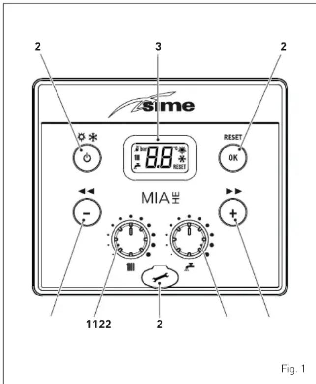
1 KNOBS
The heating knob allows the user to set the flow temperature to between 20 and 80°C during normal operation.
The domestic hot water knob allows the user to set the domestic hot water temperature to between 10 and 60°C during normal operation.
2 FUNCTIONAL BUTTONS
Press for more than one second and release to step through the operating modes (Stand-by - Summer - Winter).
This allows the engineer to scroll through the parameters or decrease the values.
+ This allows the engineer to scroll through the parameters or increase the values.
RESET This allows the engineer to confirm the selected parameter or to modify the value or to reset the appliances from a lockout failure.
Programming connector cover plug.
NOTE: pressing any one of these buttons for more than 30 seconds generates a fault on the display without preventing boiler operation. The warning disappears when the button is released.
3 DISPLAY

“SUMMER”. This symbol appears when the boiler is operating in Summer mode or if only the domestic hot water mode is enabled via the remote control. If the symbols 🙏 and 🚫 are flashing, this indicates that the chimney sweep function is active.

"WINTER". This symbol appears when the boiler is operating in Winter mode or if both the domestic hot water and heating modes are enabled via the remote control. With dedicated remote controls CR or Home, if no operating modes have been enabled both symbols and will be off.
RESET "RESET REQUIRED". This message only appears if there is a malfunction which must be or may be restored manually.

"DOMESTIC HOT WATER". This symbol is present during a request for DHW or when the chimney sweep function is operating; it flashes during the domestic hot water set point selection.

"HEATING". This symbol is present during heating operation or when the chimney sweep function is operating; it flashes during the heating set point selection.

"LOCKOUT" DUE TO NO FLAME.

"FLAME LIT".

"ALARM". This indicates that a fault has occurred. The number specifies the cause which generated the alarm (see section "Malfunction codes and possible solutions".

"MAINTENANCE REQUEST". If active, it shows it is time to perform maintenance on the boiler.
1.2 Preliminary checks

WARNING
- Should it be necessary to access the areas in the bottom part of the appliance, make sure that the system components and pipes are not hot (risk of burning).
- Before replenishing the heating system, put on protective gloves.
Prior to use the MIA-30 boiler must be installed and commissioned by a Gas Safe Registered engineer. It may be necessary for the user to occasionally have to start the boiler, for instance after a holiday or after an interruption of the gas supply. In these cases the following operations must be carried out.
- check that the gas isolation and water system valves are open
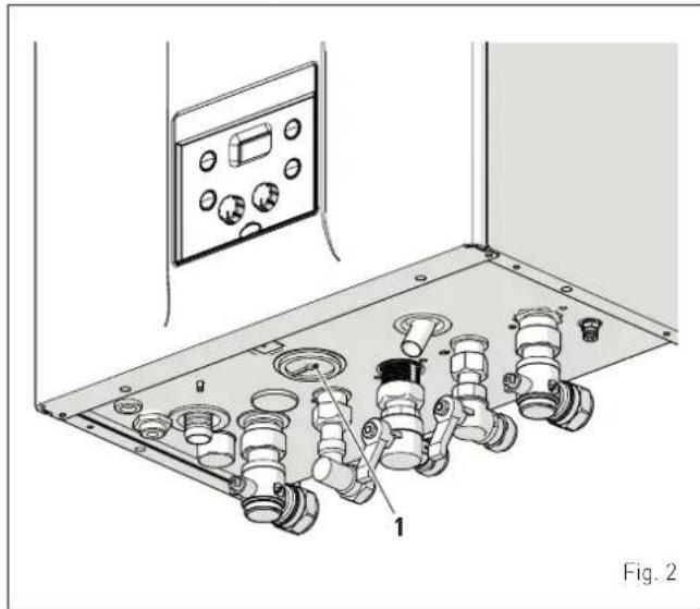
- using the pressure gauge (1) check that the pressure in the heating system, when cold, is 1-1.2 bar. If the pressure is less than this, use the external filling device to repressurise the system to 1-1.2 bar
- ensure that the filling device is turned off after use.
natural_image
Technical diagram of a mechanical assembly with labeled parts, showing internal components and a control panel (no text or symbols present)1.3 Ignition
After having carried out the preliminary checks, proceed as follows:
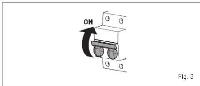
- set the main system switch to "ON"
- on the display, check that the operating mode on the display is "SUMMER" and if necessary select it by pressing and holding the button for at least 1 second. The internal temperature of the boiler will appear on the display
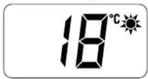
- open one or more than one hot water tap. The A should appear on the display and the boiler will ignite and stay alight until the tap is turned off.
Once the boiler has been operated in "SUMMER mode" can be selected by pressing and holding the button for at least 1 second. The internal temperature of the boiler will appear on the display. Ensure that any timers and room thermostats are in the position. The will appear on the display and the boiler will ignite.
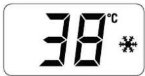
1.4 Adjusting the delivery temperature
Should you wish to increase or decrease the boiler delivery temperature, turn the dial 1111 to the desired setpoint. The value can be set to between 20°C and 80°C.
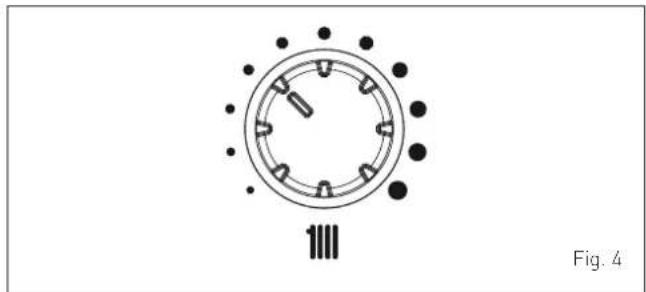
natural_image
Diagram of a circular mechanical or electrical component with radial slots and dots, labeled Fig. 4 (no text or symbols on the diagram itself)1.5 Adjusting the domestic hot water temperature
Should you wish to increase or decrease the domestic hot water temperature, turn the dial to the desired setpoint. The value can be set to between 10°C and 60°C.
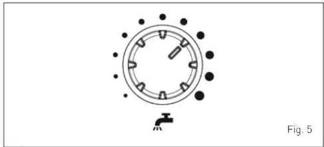
natural_image
Diagram of a circular mechanical component with evenly spaced slots and a small protrusion, labeled Fig. 5 (no text or symbols on the diagram itself)1.6 Fault / malfunction codes
If a fault/malfunction is detected during boiler operation, the message "AL" will appear on the display followed by the fault code.
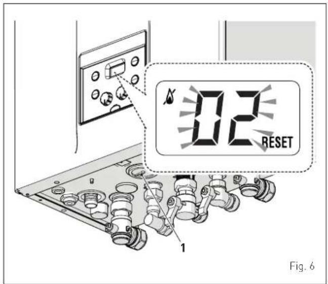
If you see alarm "02" (low water pressure in the system):
- using the pressure gauge (1) check that the pressure in the heating system, when cold, is 1-1.2 bar. If the pressure is less than this, use the external filling device to repressurise the system to 1-1.2 bar
- ensure that the filling device is turned off after use
- press and hold theOK RESET button for more than 3 seconds and check whether normal operating conditions are restored.
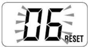
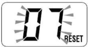
If you see alarm "06" (no flame detected) and "07" (safety thermostat intervention):
- press and hold theOK RESET button for more than 3 seconds and check whether normal operating conditions are restored.
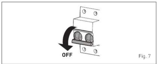
If this operation is not successful, ONLY ONE MORE ATTEMPT can be made, therefore:
- close the gas cock
- isolate the power supply
- contact the Qualified Technical Personnel.

CAUTION
Should you see an alarm not described here, contact a qualified technical professional.
2 SHUTDOWN
2.1 Temporary shutdown
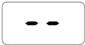
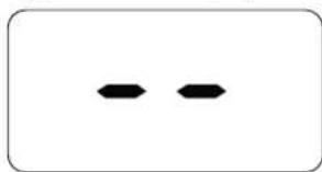
To temporarily interrupt the boiler operation press and hold the button ⏻ for at least one second, once if in "WINTER mode" or twice if in "SUMMER mode" . "-" will appear on the display the boiler will be in STAND-BY. The boiler anti freeze function will be enabled.
natural_image
Two black hexagonal shapes on a white background, enclosed in a rounded rectangle (no text or symbols)
ELECTRICAL HAZARD
The boiler will still be powered.
If the user is away temporarily, for a weekend, short trip etc and if the outside temperature is at ZERO:
- press and hold the button once if in "WINTER mode" or twice if in "SUMMER mode" to put the boiler into stand-by
- isolate the power supply
- isolate the gas cock.
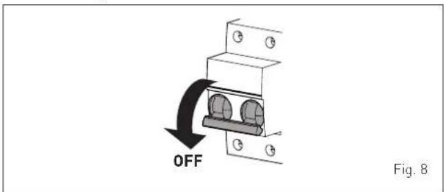

CAUTION
If the outside temperature might fall below ZERO, since the appliance is equipped with an "antifreeze function"
- ONLY PUT THE BOILER INTO STAND-BY
- leave the main system switch set to "ON" (boiler is powered)
- leave the gas cock open.
2.2 Shutting down for long periods
If the boiler is to be left unused for a long period, the following operations need to be carried out:
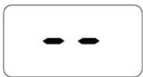
- press and hold the button ⏻ for at least 1 second, once if in "WINTER mode" 🔊 or twice if in "SUMMER mode" 🔊 to put the boiler into stand-by "-" will appear on the display
natural_image
Two black hexagonal shapes inside a rounded rectangle (no text or symbols)- isolate the power supply
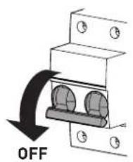
Fig. 9
3 MAINTENANCE
3.1 Servicing
As a condition of the warranty and to ensure correct operation and efficiency, it is important that the boiler is serviced every 12 months, within 30 days of the anniversary of the installation date ensure the required information is recorded in the Gas Boiler System Service Interval Record (Benchmark).

CAUTION
Maintenance must ONLY be carried out by qualified professionals who follow the indications provided in the INSTALLATION AND MAINTENANCE INSTRUCTIONS.
3.2 External cleaning

WARNING
- Should it be necessary to access the areas in the bottom part of the appliance, make sure that the system components and pipes are not hot (risk of burning).
- Before performing any maintenance, put on protective gloves.
3.2.1 Cleaning the case
When cleaning the cladding, use a cloth dampened with soap and water or alcohol for stubborn marks.

DO NOT
Do not use abrasive products.
- isolate the gas cock
- close the heating and domestic hot water isolation valves
- drain the heating and domestic hot water system if there is the risk of freezing.

CAUTION
Contact the Qualified Technical Personnel if the procedure described above cannot be easily carried out.
4 DISPOSAL
4.1 Disposal of the equipment (European Directive 2012/19/EU)
At the end of their life span, the appliance and electrical and electronic devices coming from households or classifiable as household waste must be delivered to appropriate waste collection systems, in accordance with the law and with Directive 2012/19/EU. This product was designed and manufactured for minimising its impact on the environment and on human health, but it contains components that could be detrimental if managed improperly. The symbol (crossed-out wheelie bin) depicted here and also appearing on your appliance means that the appliance at the end of its life must be managed in accordance with the law and treated as electrical and electronic waste. Before delivering the appliance for its disposal, consult the applicable provisions of the laws in force in the country where the appliance is used and get information on the authorised waste disposal facilities by contacting the relevant local offices.

DO NOT
dispose of the product with urban waste.
DESCRIPTION OF THE APPLIANCE
TABLE OF CONTENTS
5 DESCRIPTION OF THE APPLIANCE 16
5.1 Characteristics 16
5.2 Check and safety devices 16
5.3 Identification 16
5.4 Structure 17
5.5 Technical features....18
5.6 Main water circuit 19
5.7 Sensors....20
5.8 Expansion vessel 20
5.9 Circulation pump 20
5.10 Control panel 21
5.11 Wiring diagram 22
5 DESCRIPTION OF THE APPLIANCE
5.1 Characteristics
MIA-30 are condensing wall mounted boilers which Sime Ltd has produced for installation into domestic properties for heating and hot water production. The main design choices made by Sime Ltd for the MIA-30 boilers are:
- the total pre-mix microflame burner combined with a steel heat exchanger for heating and a rapid heat exchanger for DHW
- room sealed, Type C appliance. Suitable for use on sealed heating systems
- the microprocessor electronic control board, which makes the heating and domestic hot water production system easier to manage and offers the option to be connected to room thermostats or to a remote control (with Open Therm protocol) and also to an external sensor. Where connected to an external sensor, the boiler temperature varies on the basis of the external temperature, according to the selected optimal climatic curve. This provides significant energy and cost savings.
Other special features of the MIA-30 boilers are:
- the anti-freeze function which activates automatically if the temperature of the water inside the boiler falls below the threshold of the value set at parameter "tS 1.0" and, if there is an external sensor, if the external temperature falls below the threshold of the value set at parameter "tS 1.1".
- anti jamming function of the pump and diverter valve, this activates automatically every 24 hours if no request for heat has been made
- the chimney sweep function lasts 15 minutes and makes the job of the qualified technician easier when measuring the parameters and combustion efficiency
- screen display of the operating and self-diagnostic parameters with error code display when the fault occurs. This makes repair interventions easier and allows appliance operation to be restored correctly.
5.2 Check and safety devices
The MIA-30 boilers are equipped with the following check and safety devices:
- thermal safety thermostat 100°C
- 3 bar relief valve
- heating water pressure switch
- delivery sensor (SM)
- DHW sensor (SS)
- exhaust sensor (SF).

DO NOT
Do not commission or operate the appliance with safety devices which do not work or which have been tampered with.

WARNING
Safety device may only be replaced by professional qualified personnel using Sime Ltd original spare parts.
5.3 Identification
The MIA-30 boilers can be identified by means of:
1 Packaging label: this is located on the outside of the packaging and provides a code, the serial number of the boiler and the bar code
2 Energy Efficiency Label: this is positioned on the outside of the packaging to notify the User of the level of energy savings and reduced environmental pollution produced by the appliance
3 Technical Data Plate: this is located on the side of the appliance and provides the technical data, appliance performance and any other information required by law.
4 Steaker of product identification
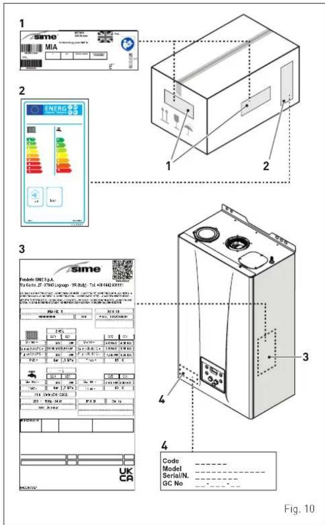

CAUTION
Tampering with, removing or failing to display the identification plate or carrying out any other operation which does not allow safe identification of the product or which may hinder installation and maintenance operations.
5.4 Structure
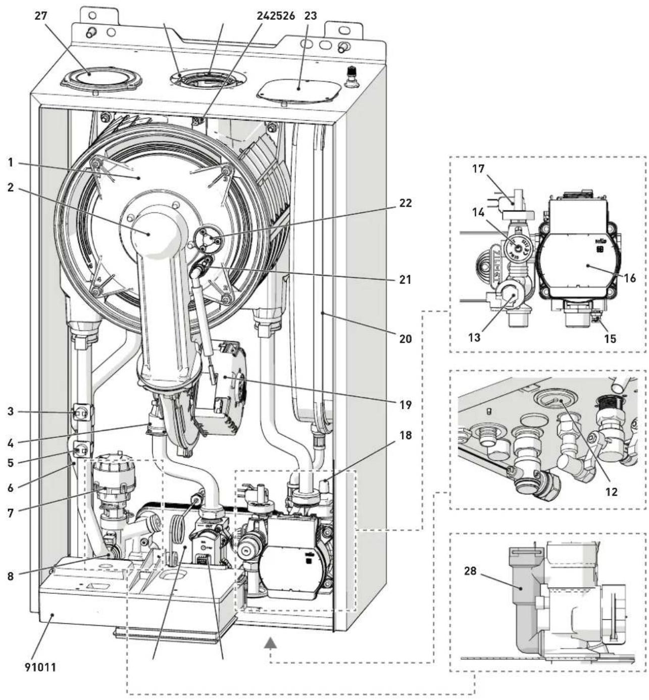
1 Combustion chamber door
2 Air/gas duct
3 Safety thermostat (TS)
4 Air-gas mixer
5 Delivery sensor (SM)
6 Condensate siphon
7 Diverter valve
8 Domestic hot water sensor (SS)
9 Control panel
10 Domestic hot water heat exchanger
11 Gas valve
12 Pressure gauge
13 Flow meter
14 System relief valve
15 Boiler drain
16 Pump
17 Water pressure switch
18 Automatic bleed valve
19 Fan
20 Expansion vessel
21 Ignition/detection electrode
22 Flame viewing window
23 Air inlet closing plate (separate ducts)
24 Exhaust sensor (SF)
25 Exhaust outlet
26 Air inlet (concentric ducts)
27 Plug/socket for attaching the air inlet pipe (separate ducts)
28 By-pass
Fig. 11
5.5 Technical features
| DESCRIPTION | MIA-30 | |
| CERTIFICATIONS | ||
| Country of intended installation GB | ||
| Fuel G20/G31 | ||
| PIN number 1312CT6307 | ||
| Category II2H3P | ||
| Type C13-C33 | ||
| Class NOx 6 (< 56 mg/kWh) | ||
| Nominal (50-30°C) Ida duplicazione! kW 30,0 | ||
| HEATING PERFORMANCE | ||
| HEAT INPUT | ||
| Nominal | kW 24 | |
| Minimum (G20-G31) | kW | 4,8 |
| HEAT OUTPUT | ||
| Nominal (80-60°C) | kW 23,6 | |
| Nominal (50-30°C) | kW 25,6 | |
| Minimum G20 (80-60°C) | kW | 4,6 |
| Minimum G20 (50-30°C) | kW | 5,0 |
| Minimum G31 (80-60°C) | kW | 4,6 |
| Minimum G31 (50-30°C) | kW | 5,0 |
| EFFICIENCY | ||
| Max useful efficiency (80-60°C) | % 98,4 | |
| Min useful efficiency (80-60°C) | % 95,5 | |
| Max useful efficiency (50-30°C) | % | 106,6 |
| Min useful efficiency (50-30°C) | % | 104,8 |
| Useful efficiency at 30% of load (40-30°C) | % | 108,6 |
| Thermal efficiency (EEC 92/42) | ★★★★★ | |
| Losses after shutdown at 50°C | W 82 | |
| DOMESTIC HOT WATER PERFORMANCE | ||
| Nominal heat input | kW 30 | |
| Minimum heat input | kW | 4,8 |
| D.H.W. flow rate ΔT 30°C | l/min 14,2 | |
| Continuous D.H.W. flow rate (ΔT 25°C / ΔT 35°C) | l/min 17,5 / 12,5 | |
| Minimum D.H.W. flow rate | l/min | 2 |
| Max / Min Pressure | bar | 7 / 0,5 |
| kPa 700 / 50 | ||
| ENERGY PERFORMANCE | ||
| HEATING | ||
| Heating seasonal energy efficiency class | A | |
| Heating seasonal energy efficiency | % 93 | |
| Sound power | dB(A) 57 | |
| DOMESTIC HOT WATER | ||
| Domestic hot water energy efficiency class | A | |
| Domestic hot water energy efficiency | % 86 | |
| Stated domestic hot water profile load | XL | |
| ELECTRICAL SPECIFICATIONS | ||
| Power supply voltage | V | 230 |
| Frequency | Hz 50 | |
| Absorbed electrical power (Qn max) | W 86 | |
| Absorbed electrical power at (Qn min) | W 55 | |
| Absorbed electrical power in stand-by | W | 4 |
| Electrical protection degree | IP | X5D |
| COMBUSTION DATA | ||
| Smoke temperature at Max/Min flow (80-60°C) | °C | 83 / 64 |
| Smoke temperature at Max/Min flow (50-30°C) | °C | 68 / 50 |
| Smoke flow Max/Min | g/s | 14,1 / 2,3 |
| CO2 at Max/Min flow rate (G20) | % 9,3 / 9,3 | |
| CO2 at Max/Min flow rate (G31) | % | 10,0 /10,0 |
| NOx measured (*) | mg/kWh 33 | |
(*) Calculated with upper calorific value (Hs)
| DESCRIPTION | MIA-30 | |
| NOZZLES - GAS | ||
| Number of nozzles No. 1 | ||
| Nozzle diameter (G20-G31) mm 5,3 | ||
| Gas consumption at Max/Min flow rate (G20) m | ^3/h 3,17 / 0,51 | |
| Gas consumption at Max/Min flow rate (G31) kg/h 2,33 / 0,37 | ||
| Gas supply pressure (G20/G31) | mbar 20 / 37 | |
| kPa 2 / 3,7 | ||
| TEMPERATURE - PRESSURE | ||
| Max operating temperature °C 85 | ||
| Heating adjustment range °C 20÷80 | ||
| Domestic hot water adjustment range °C 10÷60 | ||
| Max operating pressure | bar 3 | |
| kPa 300 | ||
| Water content in boiler l | 2,55 | |
Lower Heat Output (Hi)
G20 Hi. 9.45 kW/m³ (15°C, 1013 mbar) - G31 Hi. 12.87 kW/kg (15°C, 1013 mbar)
5.6 Main water circuit
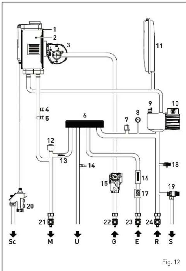
KEY:
M System flow
R System return
U Domestic hot water outlet
E Domesti hot water inlet
S Safety valve outlet
G Gas supply
Sc Condensate outlet
1 Condensing heat exchanger
2 Combustion chamber
3 Fan
4 Thermal safety thermostat (TS)
5 Delivery sensor (SM)
6 Domestic hot water heat exchanger
7 Water pressure switch
8 Pressure gauge
9 Automatic bleed valve
10 Pump
11 System expansion vessel
12 Diverter valve
13 Automatic by-pass
14 Domestic hot water sensor (SS)
15 Gas valve
16 Domestic hot water flow meter
17 Domestic hot water filter
18 Boiler drain
19 System relief valve
20 Condensate siphon outlet
21 System flow cock
22 Gas cock
23 Domestic hot water inlet cock
24 System return cock
5.7 Sensors
The sensors installed have the following characteristics:
- Dual sensor (thermal safety/output) NTC R25°C; 10kΩ β25°-85°C: 3435
- domestic hot water sensor NTC R25°C; 10kΩ B25°-85°C: 3435
- External temperature sensor NTC R25°C; 10kΩ B25°-85°C: 3435
Correspondence of Temperature Detected/Resistance
Examples of reading:
TR = 75^ R = 1925
TR = 80^ R = 1669.
| TR | 0°C | 1°C | 2°C | 3°C | 4°C | 5°C | 6°C | 7°C | 8°C | 9°C | |||
| 0°C | 27279 | 26135 | 25044 | 24004 | 23014 | 22069 | 21168 | 20309 | 19489 | 18706 | Resistance R (Ω) | ||
| 10°C | 17959 | 17245 | 16563 | 15912 | 15289 | 14694 | 14126 | 13582 | 13062 | 12565 | |||
| 20°C | 12090 | 11634 | 11199 | 10781 | 10382 | 9999 | 9633 | 9281 | 8945 | 8622 | |||
| 30°C | 8313 | 8016 | 7731 | 7458 | 7196 | 6944 | 6702 | 6470 | 6247 | 6033 | |||
| 40°C | 5828 | 5630 | 5440 | 5258 | 5082 | 4913 | 4751 | 4595 | 4444 | 4300 | |||
| 50°C | 4161 | 4026 | 3897 | 3773 | 3653 | 3538 | 3426 | 3319 | 3216 | 3116 | |||
| 60°C | 3021 | 2928 | 2839 | 2753 | 2669 | 2589 | 2512 | 2437 | 2365 | 2296 | |||
| 70°C | 2229 | 2164 | 2101 | 2040 | 1982 | 1925 | 1870 | 1817 | 1766 | 1717 | |||
| 80°C | 1669 | 1622 | 1577 | 1534 | 1491 | 1451 | 1411 | 1373 | 1336 | 1300 | |||
| 90°C | 1266 | 1232 | 1199 | 1168 | 1137 | 1108 | 1079 | 1051 | 1024 | 998 | |||
| 100°C | 973 | ||||||||||||
5.8 Expansion vessel
The expansion vessel installed on the boilers has the following characteristics:
| Description U/M MIA-30 | ||
| Total capacity l 7,0 | ||
| Prefilling pressure | kPa 100 | |
| bar 1,0 | ||
| Useful capacity l 4,45 | ||
| Maximum system content (*) | l 110 | |
(*) Conditions of:
Average operating temperature 70°C (with high temperature system 80/60°C)
Start temperature at system filling 10^ C.

CAUTION
- For systems with water content exceeding the maximum system content (as indicated in the table) an additional expansion vessel must be fitted.
- The difference in height between the relief valve and the highest point of the system cannot exceed 6 metres. If the difference is greater than 6 metres, increase the prefilling pressure of the expansion vessel and the system when cold by 0.1 bar for each meter increase.
5.9 Circulation pump
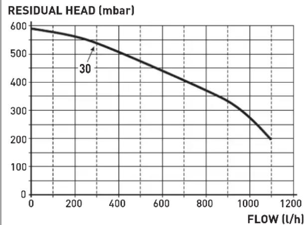
The flow-head performance curve available for the heating system is shown in the graph below.
line
| FLOW (l/h) | RESIDUAL HEAD (mbar) | | ---------- | -------------------- | | 30 | 500 |Fig. 13

CAUTION
The appliance is equipped with a by-pass which ensures water circulation in the boiler when thermostatic valves are used in the system. The heating system design should incorporate a room thermostat. Thermostatic radiator valves fitted to all radiators except the room where the room thermostat is fitted. Properties with floor areas exceeding 150squre metres should be zoned.
5.10 Control panel
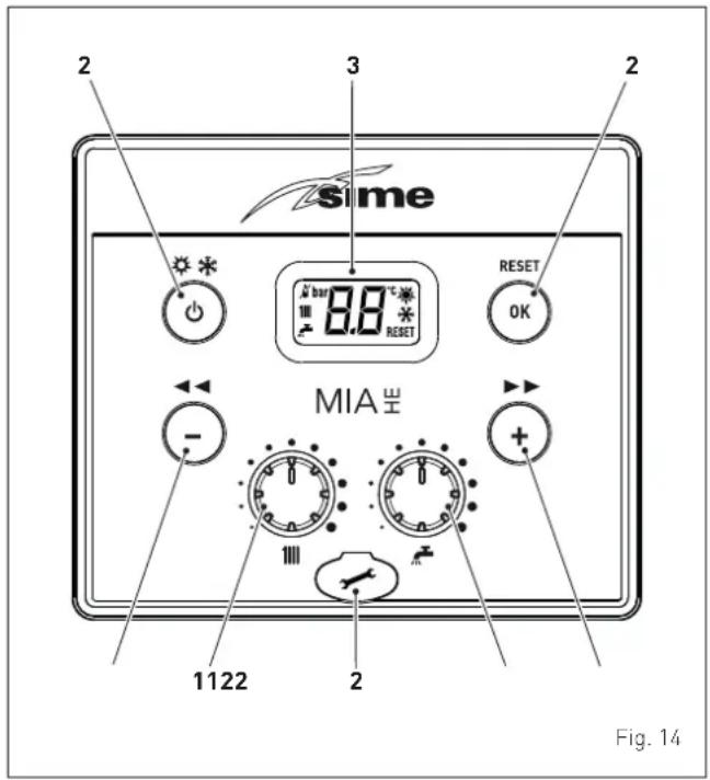
1 KNOBS
The heating knob allows the user to set the flow temperature to between 20 and 80°C during normal operation.
The domestic hot water knob allows the user to set the domestic hot water temperature to between 10 and 60°C during normal operation.
2 FUNCTIONAL BUTTONS
Press for more than one second and release to step through the operating modes (Stand-by - Summer - Winter).
This allows the engineer to scroll through the parameters or decrease the values.
+ This allows the engineer to scroll through the parameters or increase the values.
RESET This allows the engineer to confirm the selected parameter or to modify the value or to reset the appliances from a lockout failure.
Programming connector cover plug.
NOTE: pressing any one of these buttons for more than 30 seconds generates a fault on the display without preventing boiler operation. The warning disappears when the button is released.
3 DISPLAY

“SUMMER”. This symbol appears when the boiler is operating in Summer mode or if only the domestic hot water mode is enabled via the remote control. If the symbols 🙏 and 🚫 are flashing, this indicates that the chimney sweep function is active.

"WINTER". This symbol appears when the boiler is operating in Winter mode or if both the domestic hot water and heating modes are enabled via the remote control. With dedicated remote controls CR or Home, if no operating modes have been enabled both symbols and will be off.
RESET "RESET REQUIRED". This message only appears if there is a malfunction which must be or may be restored manually.

"DOMESTIC HOT WATER". This symbol is present during a request for DHW or when the chimney sweep function is operating; it flashes during the domestic hot water set point selection.
“HEATING”. This symbol is present during heating operation or when the chimney sweep function is operating; it flashes during the heating set point selection.

"LOCKOUT" DUE TO NO FLAME.

"FLAME LIT".
"ALARM". This indicates that a fault has occurred. The number specifies the cause which generated the alarm (see section "Malfunction codes and possible solutions".
5E "MAINTENANCE REQUEST". If active, it shows it is time to perform maintenance on the boiler.
5.11 Wiring diagram
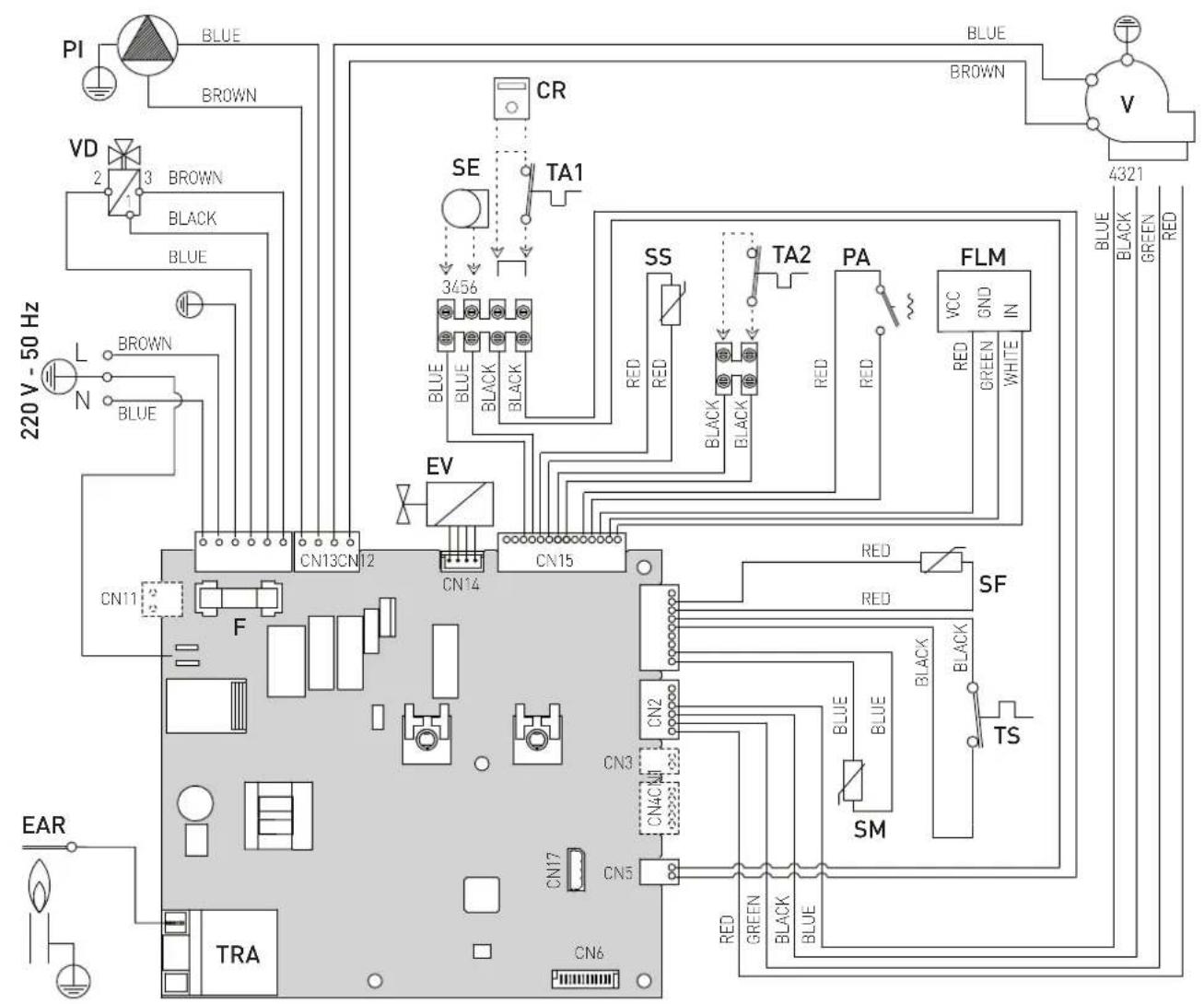
L Live
N Neutral
F Fuse (3.15AT) (3.15AT - 250V)
TRA Ignition transformer
PI Pump
V Fan
EAR Ignition / Detection electrode
EV Gas solenoid valve
SS Domestic hot water sensor (SS)
SM Delivery sensor (SM)
To connect the "TA" remove the jumper between terminals 5-6.
TS Safety thermostat
SF Exhaust sensor (SF)
FLM Flow meter
VD Diverter valve
PA Water pressure switch
TA1-TA2 Room Thermostat
SE External sensor
CR Sime EASY HOME or HOME or HOME PLUS remote control (alternative to TA1)
Fig. 15

CAUTION
Installer must:
- Connect the boiler to a 230v -50Hz single phase power supply through a fused mains switch, with at least 3mm spacing between contacts, fused at 3amps which ensures complete cut-off in overvoltage category III conditions (i.e. where there is at least 3 mm between the open contacts).
- Respect the connections L (Live) - N (Neutral).
- Ensure that the special power cable is only replaced with a cable ordered as a spare part and connected by professionally qualified personnel.

CAUTION
Installer must:
- Connect the earth wire to an effective earthing system. Sime Ltd declines all responsible for any injury or damage to persons, animals, or property as a result of failure to provide adequate earthing of the appliance.

DO NOT
Do not use water pipes for earthing the appliance.
The Benchmark Scheme
Benchmark places responsibilities on both manufacturers and installers.
The purpose is to ensure that customers are provided with the correct equipment for their needs, that it is installed, commissioned and serviced in accordance with the manufacturer's instructions by competent persons and that it meets the requirements of the appropriate Building Regulations.
The Benchmark Checklist can be used to demonstrate compliance with Building Regulations and should be provided to the customer for future reference.
Installers are required to carry out installation, commissioning and servicing work in accordance with the Benchmark Code of Practice which is available from the Heating and Hotwater Industry Council who manage and promote the Scheme.
INSTALLATION AND SERVICING INSTRUCTIONS
Installer Checklist
Please remember to carry out the following checks after installation. This will achieve complete customer satisfaction, and avoid unnecessary service calls. A charge will be made for a service visit where the fault is not
due to a manufacturing defect.
Has a correct by-pass been fitted and adjusted?
Has the system and boiler been flushed?
Is the system and boiler full of water, and the correct pressure showing on the pressure gauge?
Is the Auto Air Vent open?
Has the pump been rotated manually?
Is the gas supply working pressure correct?
Is the boiler wired correctly? (See installation manual)
Has the D.H.W. flow rate been set to the customer requirements?
Has the customer been fully advised on the correct use of the boiler, system and controls?
Has the Benchmark Checklist in the use and maintenance section of this manual, been completed?
TABLE OF CONTENTS
6 INSTALLATION 26
6.1 Receiving the product 26
6.2 Dimensions and weight.....26
6.3 Handling 26
6.4 Ventilation requirements 26
6.5 New installation or installation of a replacement appliance 27
6.6 Cleaning the system 27
6.7 Characteristics of feedwater and system treatment .. 27
6.8 Boiler installation 27
6.9 Plumbing connections....28 6.9.1 Plumbing accessories (optional)....28
6.10 Condensate outlet/collection 28
6.11 Gas supply 28
6.12 Connecting the flue 29
6.12.1 Flue Terminal Positions 29
6.12.2 Installation of coaxial flues 60/100mm - 80/125mm 30
6.12.3 Installation of separate ducts 80mm.....31
6.13 Electrical connections and External controls ..... 32
6.13.1 External temperature sensor.... 33
6.13.2 External timers and Room Thermostats... 34
6.13.3 EXAMPLE of use of the command/control device on some types of heating systems. . 34
6.14 Refilling or emptying....34
6.14.1 Method of filling a sealed system ..... 34
6.14.2 SYSTEM Filling 35
6.14.3 EMPTYING operations 35
7 COMMISSIONING 36
7.1 Preliminary operations 36
7.2 Before commissioning 36
7.2.1 Automatic self-calibrating procedure ..... 36
7.3 Parameter setting and display 37
7.4 List of parameters 37
7.5 Display of operating data and counters....39
7.6 Checks 39
7.6.1 Chimney sweep function 39
7.7 Gas conversion....40
7.8 Heating power output adjustment 41
8 MAINTENANCE 42
8.1 Servicing....42
8.2 External cleaning....42
8.2.1 Cleaning the case 42
8.3 Burner Inspection 42
8.3.1 Burner access 42
8.3.2 Cleaning the burner and the combustion chamber 43
8.3.3 Checking the ignition/detection electrode . 43
8.3.4 Final operations 43
8.4 Checks 44
8.4.1 Checking the flue 44
8.4.2 Checking the expansion vessel pressure .. 44
8.5 Circuit Board Replacement 44
8.6 Malfunction codes and possible solutions ..... 44
9 EXPLODED VIEWS 48
10 APPENDIX 1 (GUIDANCE HHIC) 55
11 APPENDIX 2 69
12 PRODUCT DATA SHEET 70
13 ANNEX AA.1 71
sime 6 INSTALLATION

CAUTION
The appliance must only be installed by the Sime Ltd Technical Service or by qualified professionals who MUST wear suitable protective safety equipment.
6.1 Receiving the product
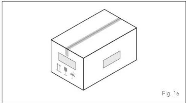
MIA-30 appliances are delivered in a single unit protected by cardboard packaging.
natural_image
Isometric line drawing of a cardboard box with internal components and label 'Fig. 16' (no text or symbols on the diagram itself)The plastic bag found inside the packaging contains the following:
- Installation, use and maintenance manual
– Paper template for boiler installation - Certificate of warranty
- Hydrostatic test certificate
- Connection pack

DO NOT
To leave packaging material around or near children since it could be dangerous. Dispose of it as prescribed by legislation in force.
6.2 Dimensions and weight
natural_image
Technical line drawing of a rectangular appliance with labeled dimensions H, W, D and internal components (no text or symbols beyond labels)| Description | MIA-30 |
| W (mm) 420 | |
| D (mm) 262 | |
| H (mm) 700 | |
| Weight (kg) 27,5 |
6.3 Handling
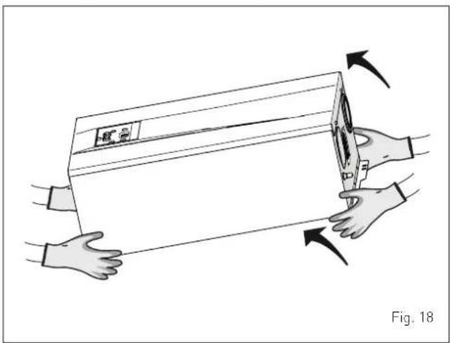
Once the packaging has been removed, the appliance is to be handled manually, tilting it slightly, lifting it and applying pressure in the points indicated in the figure.
natural_image
Illustration of hands holding a rectangular object with arrows indicating motion or force, labeled 'Fig. 18' (no text or symbols on the object itself)
DO NOT
To grip the appliance casing. Hold the "solid" parts of the appliance such as the base and structural frame.

WARNING
Use suitable tools and personal protection when removing the packaging and when handling the appliance. Observe the maximum weight that can be lifted per person.
6.4 Ventilation requirements
Detailed recommendations for the air supply are given in BS 5440-2. The following note is given for guidance. It is not necessary to have purpose provided air vents in the room or compartment that the appliance is installed.
The minimum temperature of the installation room must NOT be lower than -5 °C.

CAUTION
- Before assembling the appliance, the installer MUST make sure that the wall supports the weight.
- Remember to consider the space needed in order to access the safety/adjustment devices and to carry out maintenance interventions (see Fig. 19).
APPROXIMATE MINIMUM DISTANCES
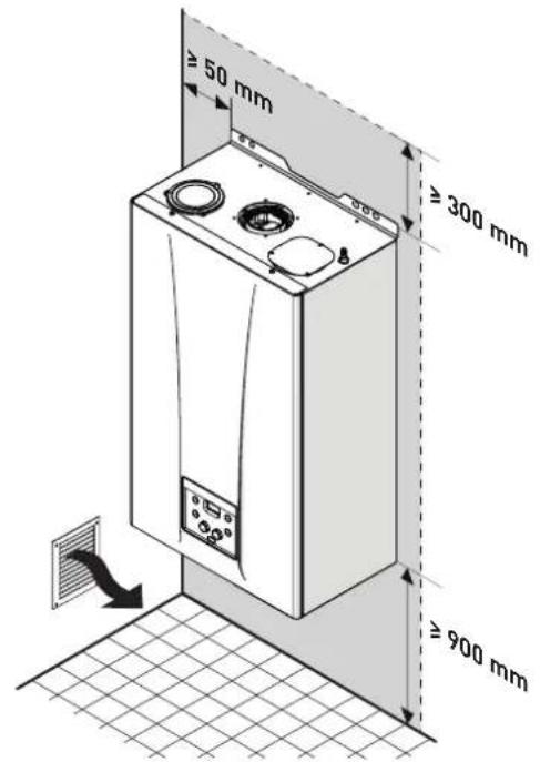
Fig. 19
6.5 New installation or installation of a replacement appliance
The boiler must be installed in a fixed location and only by specialized and qualified person in compliance with all instructions contained in this manual.
The installation of this boiler must be in accordance with the relevant requirements of the current Gas Safety (installation and use), the local building regulations and I.E.E. wiring regulations.
Detailed recommendations for air supply and fluing are given in BS5440.
The following notes are for general guidance: it is not necessary to have a purpose provided air vent in the room or compartment in which the appliance is installed.

CAUTION
It is a condition of the warranty that the boiler is installed in accordance with the instructions in this manual. The boiler must be registered with Gas Safe Register, the Benchmark record must be completed and the boiler is serviced annually and recorded in this manual.

CAUTION
If the domestic water supply is metered or should a water meter be added at a later time, a small expansion vessel should be included in the domestic water pipework.
6.6 Cleaning the system
Before connecting the boiler it is recommended that the system be flushed in accordance to BS 7593, to eliminate any foreign bodies that may be detrimental to the operating efficiency of the appliance.

CAUTION
Failure to flush and add inhibitor to the system may invalidate the warranty.
6.7 Characteristics of feedwater and system treatment
- All recirculatory systems will be subject to corrosion unless an appropriate water treatment is applied. This means that the efficiency of the system will deteriorate as corrosion sludge accumulates within the system, risking damage to pump and valves, boiler noise and circulation problems.
- Before connecting the boiler the associated central heating system must be flushed in accordance with the guidelines given in BS 7593 "Treatment of water in domestic hot water central heating systems".
- Sime Ltd recommends only the use of FERNOX products for the flushing and final treatment of the system water. This is particularly important in hard water areas. Failure to flush and add inhibitor to the system may invalidate the appliance warranty. Artificially softened water must not be used to fill the heating system. Naturally soft water areas can corrode aluminium heat exchangers. Adding Fernox F1 or Mb-1 will guard against corrosion.
- Sime Ltd promote the fitting of TF1 System filter with any new boiler installation.
- It is important to check the inhibitor concentration after installation, system modification and annually on a service visit in accordance with the manufacturer's instructions. (Note on benchmark service record this has been complete). Test kits are available from inhibitor stockists; the return of the Fernox test report should be kept with the Benchmark to validate warranty.
- Where Central heating systems are susceptible to freezing a mixture of inhibitor and anti-freeze should be added in accordance with the DWTA code of practice and the Manufactures instructions.
- The addition of sealing agents to system water is not recommended because deposits can be left in heat exchanger causing circulation issues.
6.8 Boiler installation
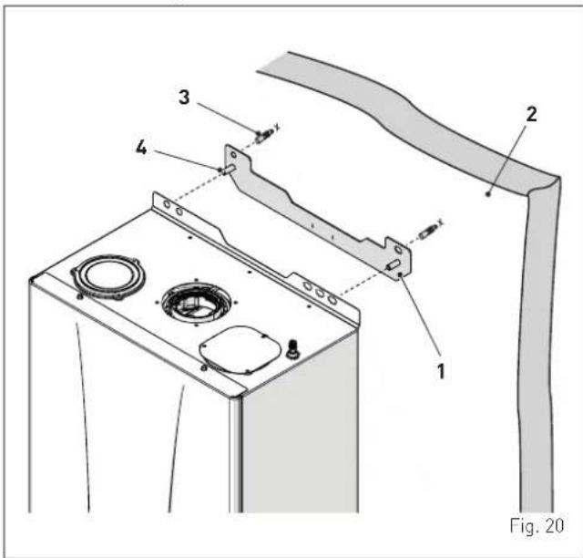
MIA-30 boilers leave the factory with a paper template for installation onto a solid wall.
For installation:
- position the bracket (1) on the wall (2), where you want to install the boiler
- check that it is straight and mark where to make the holes for the plugs
- drill the holes and insert the expansion plugs (3) which will be used to fix the bracket securely
- hook the boiler onto the pins (4) and secure it using the nuts and washers supplied.
6.9 Plumbing connections
The plumbing connections have the following characteristics and dimensions.
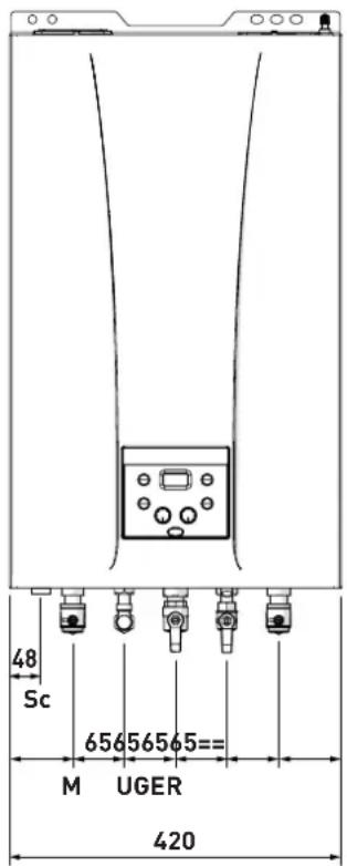
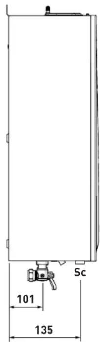
Fig. 21
| Description MIA-30 | |
| M - System flow ∅ 22 mm | |
| R - System return ∅ 22 mm | |
| U - Domestic hot water output ∅ 15 mm | |
| E - Domestic hot water inlet ∅ 15 mm | |
| G - Gas cock connection ∅ 15 mm | |
| Sc - Condensate outlet ∅ 21.5 mm | |

CAUTION
A sealed system must only be filled by a competent person (see section Method of filling a sealed system page 34).
6.9.1 Plumbing accessories (optional)
To facilitate plumbing and gas connections to the systems, the accessories as shown in the table below are available and are to be ordered separately from the boiler.
| DESCRIPTION | CODE |
| Installation plate | 8075448 |
NOTE: kit instructions are supplied with the accessory itself or are to be found on the packaging.
6.10 Condensate outlet/collection
To ensure safe disposal of the condensate produced by the flue gases, reference should be made to BS6798:2009.
The boiler incorporates a condensate trap which has a seal of 75 mm, therefore no additional trap is required.
The condensate trap can be filled prior to the installation of the flue by carefully pouring 1 litre of water into the exhaust connection.
NOTE: All pipework must have a continuous fall from the boiler and must be resistant to corrosion by condensate, copper or steel is NOT suitable. It should be noted that the connection of a condensate pipe to a drain may be subject to local building control requirements (Dealing with Condensate - see Appendix 1).
6.11 Gas supply
MIA-30 boilers leave the factory prearranged for gas G20 and can also work with G31 without the need for any type of mechanical conversion. Simply select parameter"03" (see "Parameter setting and display") page 37 and set the type of gas to be used.
If changing the type of gas to be used, carry out the entire appliance "COMMISSIONING" phase (page 36).
The gas connection must be made using seamless steel or copper tube.
Where the piping has to pass through walls, a suitable insulating sleeve must be provided.
When sizing gas piping, from the meter to the boiler, take into account both the volume flow rates (consumption) in m3/h and the relative density of the gas in question.
The sections of the piping making up the system must be such as to guarantee a supply of gas sufficient to cover the maximum output available from the boiler, limiting pressure loss between the gas meter and any apparatus being used to not greater than 1.0 mbar for family II gases (natural gas).
An adhesive data badge is sited inside the front panel; it contains all the technical data identifying the boiler and the type of gas for which the boiler is arranged.

WARNING
Once installation has been completed, check that the joints are air tight as indicated in the installation Standards.

CAUTION
It is recommended that the gas line has a suitable filter.

CAUTION
If the gas supply is changed from G20 to G31, mark the box on the TECHNICAL DATA PLATE.
G31 - 37 mbar

6.12 Connecting the flue

CAUTION
- The appliance must be installed as a room sealed device and unless stated in writing from the manufacturer, in accordance with the current edition of BS 5440-1. The information shown in this manual is for guidance and parts identification.

CAUTION
- Prior to fitting the flue, the condensate trap can be filled by carefully pouring water into the exhaust section of the flue connection.
6.12.1 Flue Terminal Positions
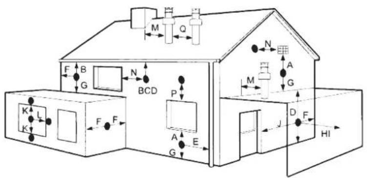
| Terminal position Minimum spacing | ||
| A Directly below an openable window, air vent or any other ventilation opening | 300 mm | 12 in |
| B Below guttering, drain pipes or soil pipes (**) | 75 mm | 3 in |
| C/D Below eaves, balconies or carport roof (*) | 200 mm | 8 in |
| E From vertical drain pipes or soil pipes | 75 mm | 3 in |
| F From internal or external corners | 300 mm | 12 in |
| G Above adjacent ground, roof or balcony level | 300 mm | 12 in |
| H From a boundary or surface facing the boiler | 600 mm | 24 in |
| I From a terminal facing the terminal | 1,200 mm | 48 in |
| J From an opening in the carport (eg door, window into dwelling) | 1,200 mm | 48 in |
| K Vertically from a terminal on the same wall | 1,500 mm | 60 in |
| L Horizont. from a terminal on the same wall | 300 mm | 12 in |
| M Horizont. from a vertical terminal to a wall | 300 mm | 12 in |
| N Horizont. from an openable window or other opening | 300 mm | 12 in |
| P Above an openable window or other opening | 300 mm | 12 in |
| Q From an adjacent vertical terminal | 600 mm | 24 in |
(*) This dimension to be used with ventilated soffits. With unvented soffits this can be reduced to 75 mm and further reduced to 25 mm when a flue shield is used to protect from the effects of heat and condensation.
(**) This can be reduced to 25 mm but it may be necessary to protect the surfaces from the effects of heat and condensation.
- If the terminal discharges into a pathway or passageway check that combustion products will not cause nuisance and that the terminal will not obstruct the passageway.
- Where the lowest part of the terminal is fitted less than 2 m [78 in] above ground, above a balcony or above a flat roof to which people have access, the terminal MUST be protected by a purpose designed guard.
- The air inlet/outlet flue duct MUST NOT be closer than 10 mm (0.4 in) to combustible material.
- In certain weather conditions the terminal may emit a plume of steam. This is normal but positions where this would cause a nuisance should be avoided.
Fig. 22
6.12.2 Installation of coaxial flues 60/100mm - 80/125mm
Coaxial flue kits that are supplied separately. The diagrams below, illustrate some examples of fluing options allowed and the maximum lengths than can be achieved. It is essential that a flue gas analysis point is made available directly above the boiler.
IMPORTANT:
- The insertion of each additional 90^ bend with a diameter of 60/100 (code 8095850) reduces the available section by 1.5 meters.
- The insertion of each additional 90^ bend with a diameter of 80/125 (code 8095870) reduces the available section by 2 meters.
- Each additional 45^ curve installed a diameter of 60/100 (code 8095950) reduces the available length by 1.0 metres.
- Each additional 45^ curve installed a diameter of 80/125 (code 8095970) reduces the available length by 1.0 metres.
HORIZONTAL FLUES MUST BE LEVEL
NOTE: Before connecting accessories, it is always advisable to lubricate the internal part of the gaskets with silicon products. Avoid using oils and greases.
| Model | Length of pipe ∅ 60/100 | Length of pipe ∅ 80/125 | ||||
| H(m) | V(m) | H(m) | V(m) | |||
| Min. | Max. | Min. | Max. | |||
| MIA-30 | 6 | 1,3 | 7 | 10 | 1,2 | 13 |
LIST OF 60/100 ACCESSORIES
1a Coaxial duct kit L. 790 code 8096250
1b Telescopic coaxial duct kit L. 695 code 8098605
2a Extension L. 1000 code 8096150
2b Extension L. 500 code 8096151
3 Vertical extension L. 140 with coupling code 8086950
5 Tile for joint code 8091300
6 Terminal for roof exit L. 1285 code 8091212 (includes 8086950)
LIST OF 080/125 ACCESSORIES
1 Coaxial duct kit L. 785 code 8096253
2a Extension L. 1000 code 8096171
2b Extension L. 500 code 8096170
3 Adapter for ø 80/125 code 8093150
5 Tile for joint code 8091300
6 Terminal for roof exit L. 1285 code 8091212 (includes 8086950)
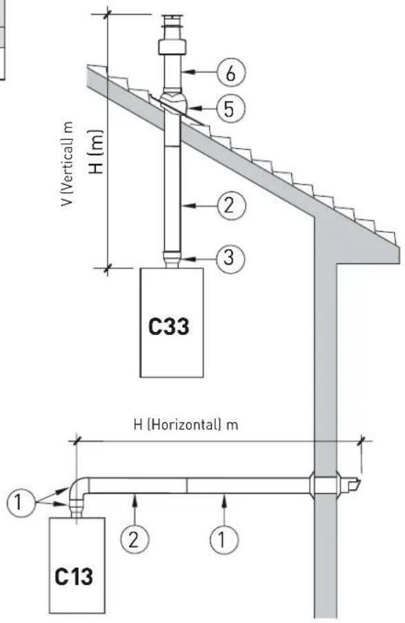
Fig. 23
6.12.3 Installation of separate ducts 80mm
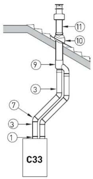
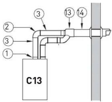
The boiler can be installed with separate air inlet and exhaust ducts. The figure below illustrate some examples of the fluing options allowed and the associated losses of the accessories. The total load loss is the sum of the load losses of the accessories used. The maximum load loss must not exceed 15 mm H2O, and the maximum flue length must not exceed 25 m inelt and exhaust.
NOTE
Before connecting accessories, it is always advisable to lubricate the internal part of the gaskets with silicon products. Avoid using oils and greases.
| MIA-30Load loss - mm H_2O | ||
| Inlet Exhaust | ||
| 1 Air/smoke divider, code 8089912 0 0 | ||
| 2 90° bend, code 8077450 (6 pcs) | 0.25 | 0.30 |
| 3a Extension 80mm L. 1000, code 8077351 (6 pcs) | 0.20 | 0.20 |
| 3b Extension 80mm L. 500, code 8077350 (6 pcs) | 0.10 | 0.10 |
| 7 45° bend, code 8077451 (6 pcs) | 0.20 | 0.20 |
| 9 Inlet/ exhaust fitting, code 8091401 | -- | -- |
| 10 Articulated tile, code 8091300 | -- | -- |
| 11 Vertical roof terminal, code 8091204 * | 1.10 | 0.15 |
| 13 Inlet/ exhaust fitting, code 8091401 | -- | -- |
| 14 Coaxial Terminal, code 8091204 * | 1.10 | 0.15 |
| * This loss includes the losses with use of item 9 or 13 | ||
Fig. 24
Plug/socket for attaching the air inlet pipe (separate ducts)
The plug (1) must be modified as detailed below before it can be used:
– disassemble the plug (1) from the boiler
- remove the pre-cut bottom (2) from inside the plug
- turn the plug over and refit it on the opening it was removed from, first slotting in the gasket (3). The cylindrical part should be facing upwards; the first part of the piping will be attached here.
NOTE: If the combustion air inlet duct needs to be connected to the right attachment, move the air inlet closing plate (4) from the right to the left and proceed with modifying the plug (1) as described above.
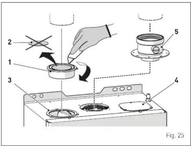
KEY:
1 Plug/socket for attaching the air inlet pipe (separate ducts)
2 Pre-cut bottom
3 Gasket
4 Air inlet closing plate
5 Smoke outlet collar
CAUTION
- The maximum total length of the ducts, obtained by adding the lengths of the inlet and outlet pipes, is determined by the load losses of the individual accessories used and must not exceed 15 H20 mm.
- For all boiler versions, the total extension for ducts 80 mm must not in any case exceed 25 m (inlet) + 25 m (outlet).
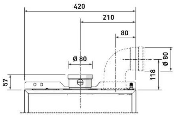
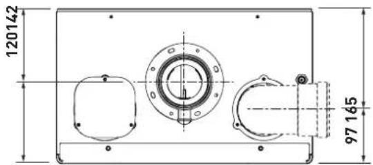
Fig. 26
6.13 Electrical connections and External controls
The boiler is supplied with a mains cable. Connect the boiler to a 230V -50Hz single phase power supply through a fused mains switch, with at least 3 mm spacing between contacts, fused at 3 amps.
If this cable needs to be replaced, an original spare must be requested from Sime Ltd.
The heating control of the boiler can be achieved by connection of either a volt free room thermostat, room thermostat/timer or a dedicated control (listed below). For connection details see section "External timers and Room Thermostats").
| DESCRIPTION CODE | |
| External sensor kit (β=3435, NTC 10KOhm at 25°C) | 8094101 |
| Power cable (dedicated) 6329477 | |
| Remote control EASY HOME (not supplied) 8092279 | |
| Remote control HOME (not supplied) 8092280 | |
| Remote control HOME PLUS (not supplied) 8092281 |

CAUTION
Only qualified persons in compliance with the instructions contained in this manual are permitted to install, commission and maintain this boiler. The installation of this boiler must be in accordance with the relevant requirements of the current Gas Safety (installation and use) Regulation 1998, the local building regulations, and I.E.E. wiring regulations.

WARNING
Before carrying out any interventions described:
- isolate the power supply
- isolate the gas cock
- avoid contact with any hot surfaces.
To make the electrical connections:
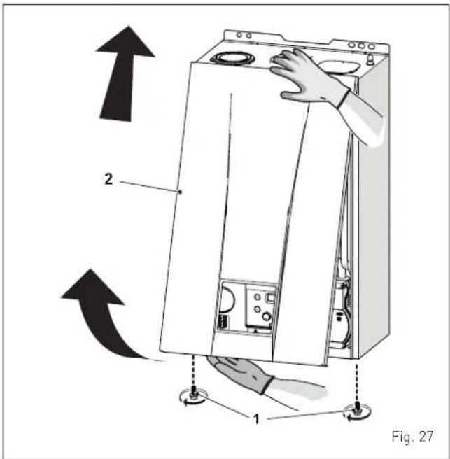
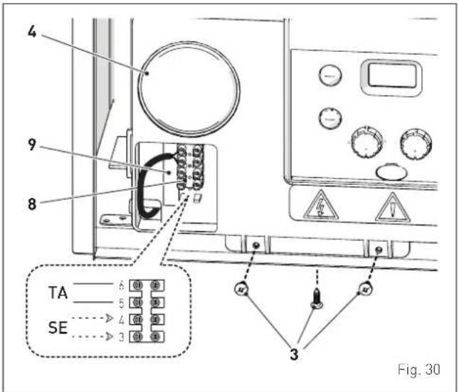
- remove the screws (1), pull the front panel (2) forwards and release it from the top by lifting it
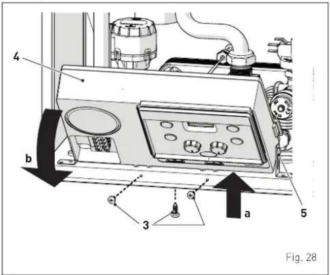
- remove the screws (3) securing the control panel (4)
- move the panel (4) upwards (a) but keeping it in the side guides (5) to the end of travel
- bring it forwards and down (b) until it is horizontal
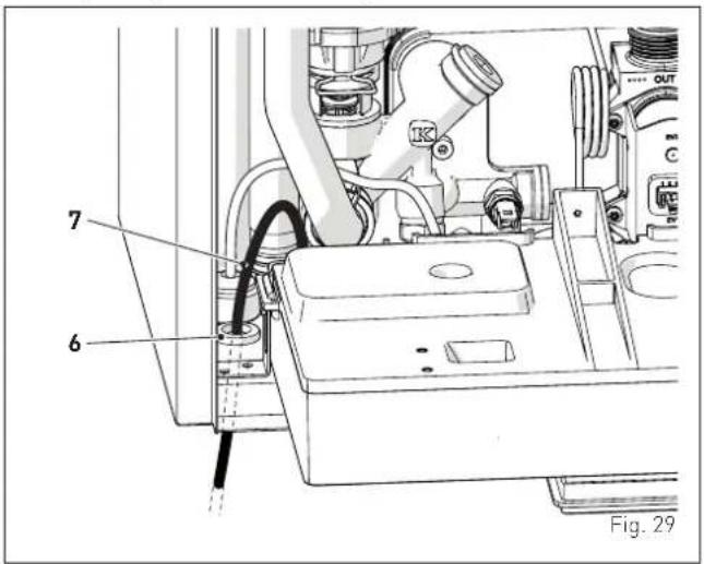
- insert the connection wires through the grommet (6) and the opening (7) on the control panel
- bring the control panel (4) to the original position and secure it with the screws (3) which were removed previously
- connect the component wires to the terminal board (8) following the indications provided on the data plate (9) and as shown in section "Wiring diagram".

CAUTION
It is compulsory:
- to use an omnipolar cut-off switch, disconnect switch, in compliance with EN standards (contact opening of at least 3 mm)
- if the power cable is to be replaced, that ONLY a special cable is used with a factory produced re-wired connector, ordered as a spare part and connected by a professionally qualified person
- to connect the earth wire to an effective earthing system (*)
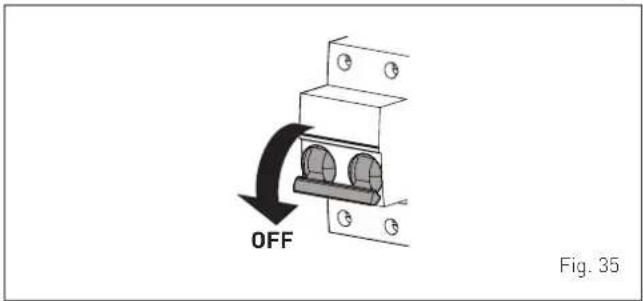
- that before any work is done on the boiler, the mains power is disconnected by setting the main system switch to "OFF".
(*) Sime Ltd declines all responsible for any injury or damage to persons, animals, or property as a result of failure to provide adequate earthing of the appliance.

DO NOT
Do not use water pipes for earthing the appliance.
6.13.1 External temperature sensor
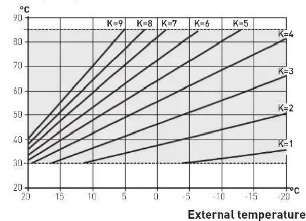
The boiler is designed for connection to an external temperature sensor code 8094101, which will automatically regulate the central heating delivery temperature.
This means that the delivery temperature of the boiler can vary on the basis of the external temperature depending on the climatic curve selected from those shown in the diagram (Fig. 31).
When fitting the sensor on the outside of the building, follow the instructions provided on the packaging of the product itself.
Climatic curve
Delivery temperature
line
| External temperature | K=1 | K=2 | K=3 | K=4 | K=5 | K=6 | K=7 | K=8 | K=9 | | --------------------- | ---- | ---- | ---- | ---- | ---- | ---- | ---- | ---- | ---- | | 20 | 30 | 30 | 30 | 30 | 30 | 30 | 30 | 30 | 30 | | 15 | 30 | 30 | 30 | 30 | 30 | 30 | 30 | 30 | 30 | | 10 | 30 | 30 | 30 | 30 | 30 | 30 | 30 | 30 | 30 | | 5 | 30 | 30 | 30 | 30 | 30 | 30 | 30 | 30 | 30 | | 0 | 30 | 30 | 30 | 30 | 30 | 30 | 30 | 30 | 30 | | -5 | 30 | 30 | 30 | 30 | 30 | 30 | 30 | 30 | 30 | | -10 | 30 | 30 | 30 | 30 | 30 | 30 | 30 | 30 | 30 | | -15 | 30 | 30 | 30 | 30 | 30 | 30 | 30 | 30 | 30 | | -20 | 30 | 30 | 30 | 30 | 30 | 30 | 30 | 30 | 30 |Fig. 31

CAUTION
If there is an external sensor, turn the heating knob until the required curve K has been selected within the range K=0.0 - K=9.0 in order to select the optimal climatic curve for the system and therefore the delivery temperature based on the external temperature.
6.13.2 External timers and Room Thermostats
The heat demand can be by a "clean contact" conforming to EN607301 connected to TA (see section "Wiring diagram") or by use of a dedicated Sime Remote Control (Home or Home Plus). The boiler will automatically detect when a dedicated control is connected.
6.13.3 EXAMPLE of use of the command/control device on some types of heating systems
KEY
M System flow
R System return
CR Remote control
SE External temperature sensor
TA Room thermostat for boiler activation
TZ1÷TZ3 Room thermostat for the zone
VZ1-VZ3 Zone valves
RL1-RL3 Zone relays
P1-P3 Zone pump
TSB Low temperature safety thermostat
ONE DIRECT ZONE system, external sensor and room thermostat.
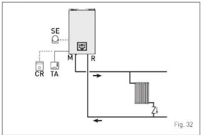
flowchart
graph TD
    A["CR"] --> B["TA"]
    C["SE"] --> D["M"]
    D --> E["R"]
    F["Zener Diode"] --> G["Diode symbol"]
    style A fill:#f9f,stroke:#333
    style B fill:#ccf,stroke:#333
    style C fill:#cfc,stroke:#333
    style D fill:#fcc,stroke:#333
    style E fill:#ffc,stroke:#333
    style F fill:#fcc,stroke:#333
    style G fill:#cff,stroke:#333
MULTI ZONE system - with zone valve, room thermostat and external sensor.
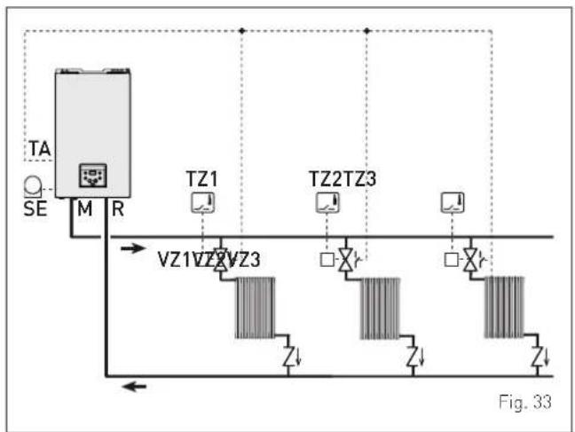
flowchart
graph TD
    TA["TA"] --> M["M"]
    SE["SE"] --> M
    M --> R["R"]
    R --> VZ1["VZ1"]
    R --> VZ2["VZ2"]
    R --> VZ3["VZ3"]
    VZ1 --> Z1["Z1"]
    VZ2 --> Z2["Z2"]
    VZ3 --> Z3["Z3"]
    TZ1["TZ1"] --> Z1
    TZ2["TZ2"] --> Z2
    TZ3["TZ3"] --> Z3
    style TA fill:#f9f,stroke:#333
    style SE fill:#ccf,stroke:#333
    style M fill:#cfc,stroke:#333
    style R fill:#fcc,stroke:#333
    style VZ1 fill:#ffc,stroke:#333
    style VZ2 fill:#ffc,stroke:#333
    style VZ3 fill:#ffc,stroke:#333

CAUTION
Set the parameter "tS 1.7 = DELAY SYSTEM PUMP ACTIVATION to allow the opening of zone valve VZ."
MULTI ZONE system - with pump, room thermostat and external sensor.
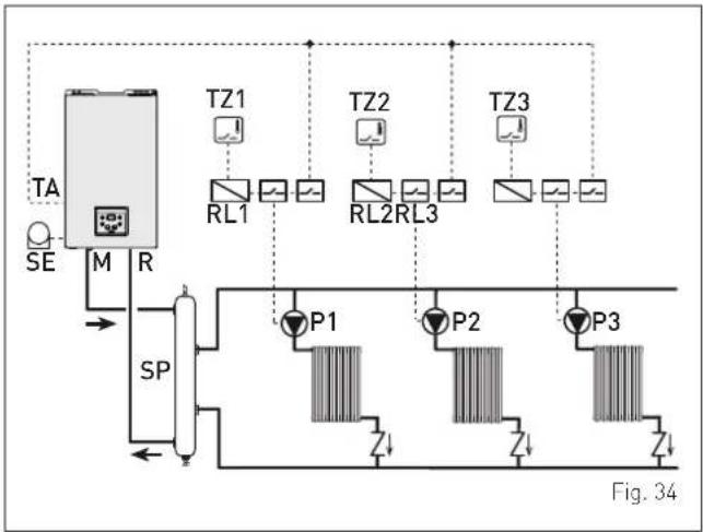
flowchart
graph TD
    A["TA"] --> B["SE"]
    B --> C["M"]
    C --> D["R"]
    D --> E["SP"]
    E --> F["P1"]
    E --> G["P2"]
    E --> H["P3"]
    F --> I["Z↓"]
    G --> J["Z↓"]
    H --> K["Z↓"]
    L["TZ1"] --> M["RL1"]
    N["TZ2"] --> O["RL2"]
    P["TZ3"] --> Q["RL3"]
    style A fill:#f9f,stroke:#333
    style L fill:#ccf,stroke:#333
    style N fill:#ccf,stroke:#333
    style P fill:#ccf,stroke:#333
    style Q fill:#ccf,stroke:#333
6.14 Refilling or emptying
Before carrying out the operation described below, isolate the boiler power supply.
Ensure that the inhibitor concentration is correct on refilling.
6.14.1 Method of filling a sealed system
A sealed system must only be filled by a competent person using a method similar to that shown in figure below.

flowchart
graph LR
    A["Heating circuit return"] --> B["Stop valve"]
    B --> C["Hose unions"]
    C --> D["Filling loop temporarily connected"]
    D --> E["Double chech valve assembly"]
    E --> F["Test cock"]
    F --> G["Stop valve"]
    G --> H["Mains water supply"]
6.14.2 SYSTEM Filling
Remove the front panel:
- remove the two screws (1), pull the front panel (2) forwards and release it from the top by lifting it.

Fig. 37
Domestic hot water circuit:
- open the domestic hot water inlet isolation valve (4)
- open each of the DHW taps until air is expelled.
Heating circuit:
- open the isolation and air bleeding valves in the highest points of the system
- loosen the automatic bleed valve (3)
- open the heating circuit isolation valves (8) and (9)
- activate the filling system "Method of filling a sealed system", and fill the heating system until a pressure of 1-1.2 bar is shown on the pressure gauge (5)
- stop the filling system
- check that there is no air in the system by bleeding all the radiators and the circuit on the high points of the system. Connect a suitable pipe and use the heat exchanger bleed point (10) to vent the primary heat exchanger
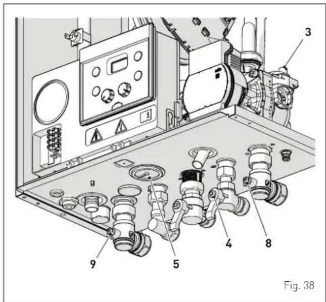
NOTE: to completely remove all air from the system, it is recommended that this operation is repeated a number of times.
- check the pressure on the pressure gauge (5) and if necessary top up until the correct pressure reading appears
- close the automatic bleed valve (3)
- it is recommended that the condensate trap is filled prior to fitting the flue, by carefully pouring water into the exhaust connection.
Refit the front panel of the boiler hooking it on at the top, pushing it forwards and securing it with the screw (1) which was removed previously.
6.14.3 EMPTYING operations
Domestic hot water circuit:
- close the domestic hot water circuit isolation valve (4)
- open one or more than one hot water taps and drain the domestic hot water circuit.
Boiler:
- loosen the automatic bleed valve (3)
- close the heating circuit isolation valves (8) and (9)
- connect a rubber hose to the boiler drain valve (7) and open it
- when it has fully emptied, close the drain valve (7)
- close the automatic bleed valve (3).
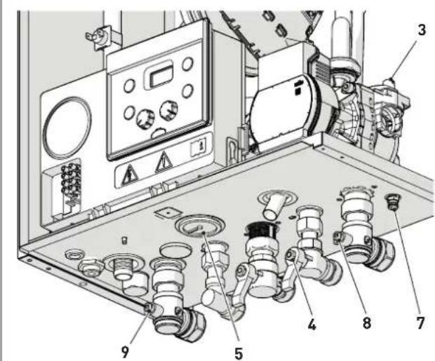
Fig. 39
7.1 Preliminary operations

WARNING
- Should it be necessary to access the areas in the bottom part of the appliance, make sure that the system components and pipes are not hot (risk of burning).
- Before replenishing the heating system, put on protective gloves.
Before commissioning the appliance, check that:
- the type of gas is correct for the appliance
- the gas isolation valves for the heating system and the water system are open
- the system pressure as shown on the pressure gauge when the system is cold, is between 1 and 1.2 bar
- the pump impeller rotates freely
- the siphon has been filled
- the flue is fitted correctly.
7.2 Before commissioning
After having carried out the preliminary operations, proceed as follows:
- set the main system switch to "ON"
- the type of gas for which the boiler has been calibrated, "nG" (methane) or "LG" (LPG,) will appear followed by the power. Finally "-"will appear on the display
natural_image
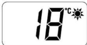
Two black diamond shapes inside a rounded rectangle (no text or symbols)- press the button ⏻ once for at least 1 second to select "SUMMER mode" ⚙. The value of the delivery sensor detected at that moment will appear on the display
7.2.1 Automatic self-calibrating procedure
Carry out the "Automatic self-calibrating procedure" as follows:
- turn the domestic hot water knob as far as it will go.
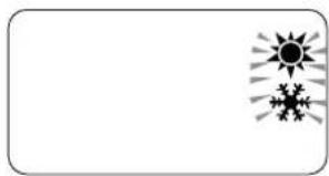
- press and hold down the buttons OK and + at the same time for approximately 12 seconds until the flashing symbols and ✕ appear on the display
natural_image
Simple line drawing of two sun icons above a starburst shape, no text or symbols present- as soon as the symbols begin to flash, release the buttons OK and + and press the button ⏻, within 3 seconds
- the "Automatic self-calibrating procedure" starts
- to dissipate the heat, tun on one or more DHW taps
- the values flash on the display: "99" (maximum value), followed by an "intermediate value" and finally "00" (minimum value)

It may take up 15 minutes for the "self-calibrating procedure" to end and the message "SUMMER mode" to reappear on the display Once the procedure has terminated:
- close the taps opened previously and check that the appliance shuts down.
If there is a fault, the message "AL" will appear on the display followed by the fault code (eg. "06" - no flame detected).
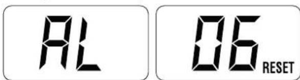

CAUTION
To restore the start conditions press and hold the button OK RESET for more than 3 seconds. This operation can be performed up to a maximum of 6 times without the "self-calibrating procedure" being interrupted.
- press the button once to select "WINTER mode". The value of the heating water temperature detected at that moment will appear on the display
- operate the heating controls and check that the boiler starts and operates correctly
- using the procedure shown in section "Chimney sweep function" complete inlet working gas pressure test and a flue gas analysis.
- record in Benchmark commissioning Check list (page 46).
7.3 Parameter setting and display
To go into the parameter menu:
- from the selected mode (eg. WINTER)
- press the buttons— and OK (approximately 5 seconds) at the same time until "tS" (installer) appears on the 2 digits of the display which alternate with "0.1" (parameter number) and a "5" (set value)
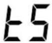

- press the button+ to scroll up the list of parameters and then - to scroll down the list
NOTE: holding the buttons + or - increases the speed of the scrolling movement.
- once the required parameter has been reached, press the button OK for approximately 3 seconds to confirm and access the set value which will then flash and can then be modified

- to modify the value in the permitted range, press the buttons + to increase it or - to decrease it
- once the required value has been reached, press the button OK to confirm.
When all the parameter modifications have been made, exit the parameter menu by pressing and holding down the buttons — and OK at the same time for approximately 5 seconds until the initial screen is displayed.
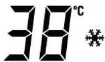
7.4 List of parameters
| Type | No. | Description Range U/M Step Default | ||||
| CONFIGURATION | ||||||
| tS 0.1 | Index s | showing boiler power in kW 1 = 30 kW - 1 - | ||||
| tS 0.2 | Hydraulic configuration | 0 = combi1 = system2 = N/A3 = N/A4=instant with solar power input5 = open vent6 = boiler with heat pump | -10 | |||
| tS 0.3 | Gas Type Configuration | 0 = G201 = G31 | -10 | |||
| tS 0.4 | Combustion configuration | 0 = sealed chamber with combustion control1 = open chamber with smoke thermostat2 = Low Nox | -10 | |||
| tS 0.8 | External sensor value correction -5 .. +5 °C 10 | |||||
| tS | 0.9 | Ignition fan speed | 80 .. 160 | RPMx25 | 1 | 128 |
| DOMESTIC HOT WATER - HEATING | ||||||
| tS | 1.0 | Boiler Antifreeze Threshold | 0 .. +10 | °C | 1 | 3 |
| tS 1.1 | External Sensor Antifreeze Threshold--- = Disabled | -9 .. +5 °C 1 | -2 | |||
| tS | 1.2 | Heating Curve Incline | 0 .. 80 | - | 1 | 20 |
| tS | 1.3 | Minimum Heating Temperature Adjustment | 20 .. Par tS 1.4 | °C | 1 | 20 |
| tS | 1.4 | Maximum Heating Temperature Adjustment | Par tS 1.3 .. 80 | °C | 1 | 80 |
| tS | 1.5 | Maximum power in CH mode | 0 .. 100 | % | 1 | 100 |
| tS 1.6 | Heating Post-Circulation Time | 0 .. 99 | seconds x 10 | 1 | 3 | |
| tS 1.7 | Heating Pump Activation Delay | 0 .. 60 | seconds x 10 | 1 | 0 | |
| tS | 1.8 | Heating Re-ignition Delay | 0 .. 60 | Min | 1 | 3 |
| tS 1.9 | Domestic Hot Water Modulation with Flow meter | 0 = Disabled1 = Enabled | -11 | |||
| tS | 2.0 | Maximum power domestic hot water | 0 .. 100 | % | 1 | 100 |
| Type No. Description Range U/M Step Default | ||||||
| tS 2.1 | Minimum power heating/domestic hot water (premixed) | 0 .. 100 % 1 0 | ||||
| tS 2.2 | Domestic hot water preheating enabling | 0 = OFF1 = ON | - 1 0 | |||
| tS 2.5 | Auxiliary TA function | 0 = according to TA1 = TA Antifreeze2 = domestic hot water disabled | - 1 0 | |||
| tS 2.6 | Zone Valve / Pump Relaunch Delay 0 .. 99 Min 1 1 | |||||
| tS 2.8 | DHW activation delay with solar power | 0 .. 30 Min 1 0 | ||||
| tS 2.9 | Anti-legionella Function (Only hot water tank) | --- = Disabled50 .. 80 | - 1 -- | |||
| tS | 3.0 | Maximum domestic hot water temperature | 35 .. 67 | °C | 1 | 60 |
| tS 3.5 | Digital / analogue Pressure switch | 0 = water pressure switch1 = water pressure transducer (with ALL 09)2 = water pressure transducer (without ALL 09) | - 1 0 | |||
| tS | 3.9 | Modulating pump minimum speed | 20 .. 100 | % | 1 | 30 |
| tS 4.0 | Modulating Pump Speed | --- = No modulationAU = Automatic 30 .. 100 | % | 10 | AU | |
| tS | 4.1 | ΔT Modulating pump delivery/Return | 10 .. 40 | °C | 1 | 20 |
| tS 4.2 | Select heat pump or boiler convenience (only if tS 0.2 = 6) | -20 .. 30 | °C | - 5 | ||
| tS 4.3 | Heat pump boiler aid activation delay (only if tS 0.2 = 6) | 1 .. 180 Min | - 20 | |||
| tS 4.7 | System | pump forcing (only in winter mode) | 0 = Disabled1 = Enabled | - 1 0 | ||
| RESET | ||||||
| tS | 4.8 | INST Parameter set to default | 0 .. 1 | - | - | 0 |
In the event of a fault/malfunction the message "AL" will appear on the display alternating with the alarm number eg. "AL 04" (Domestic Hot Water Sensor Fault).
Before repairing the fault:
- disconnect the appliance from the mains power by setting the main switch to "OFF"
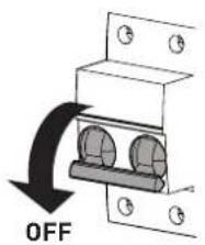
Fig. 40
- as a precautionary measure, close the gas isolation valve.
Resolve the problem and start-up the boiler again.
NOTE: after having repaired the fault, when the alarm number appears on the display together with the message RESET (see figure), press the button OK (RESET) for approximately 3 seconds to start the appliance up again.
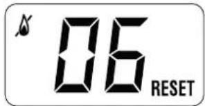
7.5 Display of operating data and counters
Access the operating data "In" and the counters "CO" as follows:
- from the operating screen in the mode enabled at that moment (WINTER or SUMMER)
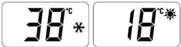
- go into "INFO" by pressing the buttons + and - at the same time for more than 3 seconds until "In" appears alternating with "0.0" (information number) and "25" (eg. value)

From this point, the technician has 2 options:
- scroll through the list of "info" and "counters" by pressing the button+. This way, scrolling will be in sequence
- display the "activated alarms" (no more than 10) by pressing the button - . Once in this section, proceed with button + or - .
When all the values have been displayed, exit the menu by pressing and holding down the button OK for approximately 5 seconds until the initial screen is displayed.
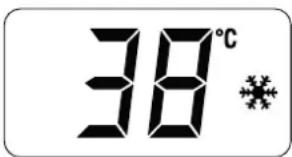
TABLE OF INFORMATION DISPLAYED
| Type | No. | Description Range U/M Step | |||
| In 0.0 SW version | |||||
| In 0.1 External sensor (SE) - 9 .. 99 °C 1 | |||||
| In 0.2 | Delivery sensor temperature (SM) | - 9 .. 99 °C 1 | |||
| In 0.3 | Exhaust temperature [SF] | - 9 .. 99 °C 1 | |||
| In 0.4 | Domestic hot water sensor temperature [SS] | - 9 .. 99 °C 1 | |||
| In 0.5 AUX | auxiliary sensor - 9 .. 99 °C 1 | ||||
| In 0.6 | Actual heating SET temperature | Par. 13 ... Par. 14 | °C | 1 | |
| In | 0.7 | Power level | 0 .. 99 | % | 1 |
| In 0.8 DHW | Flow rate 0 .. | 99 l/min | 0 | 1 | |
| In 0.9 | Water pressure transducer reading (when fitted) | 0 .. 99 | bar | 0.1 | |
| In 1.0 | Actual speed fan number | 0 .. 99 | RPM x 100 | 1 | |
TABLE OF COUNTER DISPLAYED
| Type | No. | Description | Range | U/M | Step |
| CO | 0.0 | total no. of boiler operating hours | 0 .. 99 | h x 1000 | 0.1; from 0.0 to 9.9; 1; from 10 to 99 |
| CO | 0.1 | total no. of burner operating hours | 0 .. 99 | h x 1000 | 0.1; from 0.0 to 9.9; 1; from 10 to 99 |
| CO | 0.2 | total no. of burner ignitions | 0 .. 99 | h x 1000 | 0.1; from 0.0 to 9.9; 1; from 10 to 99 |
| CO | 0.3 | total no. faults | 0 .. 99 | x 1 | 1 |
| CO | 0.4 | total no. of times installer parameters "IS"accessed | 0 .. 99 | x 1 | 1 |
| CO | 0.5 | total no. of times OEM parameters accessed | 0 .. 99 | x 1 | 1 |
| CO | 0.6 | Countdown to the next service | 1 .. 199 | months | 1 |
TABLE OF ACTIVATED ALARMS/FAULTS
| Type | No. | Description |
| AL | 00 | Last activated alarm/fault |
| AL | 01 | Last but one activated alarm/fault |
| AL | 02 | Third from last activated alarm/fault |
| AL | 03 | Previous activated alarm/fault |
| AL | 04 | Previous activated alarm/fault |
| AL | 05 | Previous activated alarm/fault |
| AL | 06 | Previous activated alarm/fault |
| AL | 07 | Previous activated alarm/fault |
| AL | 08 | Previous activated alarm/fault |
| AL | 09 | Previous activated alarm/fault |
7.6 Checks
7.6.1 Chimney sweep function
The chimney sweeper function is used by the qualified maintenance technician to check the mains gas pressure, detect the combustion parameters and to measure the combustion efficiency. A combustion analysis should not be conducted until a satisfactory inlet working pressure test has been completed.
This function lasts 15 minutes and is activated by proceeding as follows:
- if the panel (2) has not already been removed, remove the two screws (1), pull the front panel (2) forwards and release it from the top by lifting it
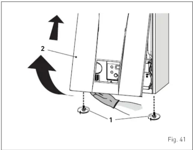
sime
- remove the screws (3) securing the control panel (4)
- move the panel (4) upwards (a) but keeping it in the side guides (5) to the end of travel
- bring it forwards and down (b) until it is horizontal
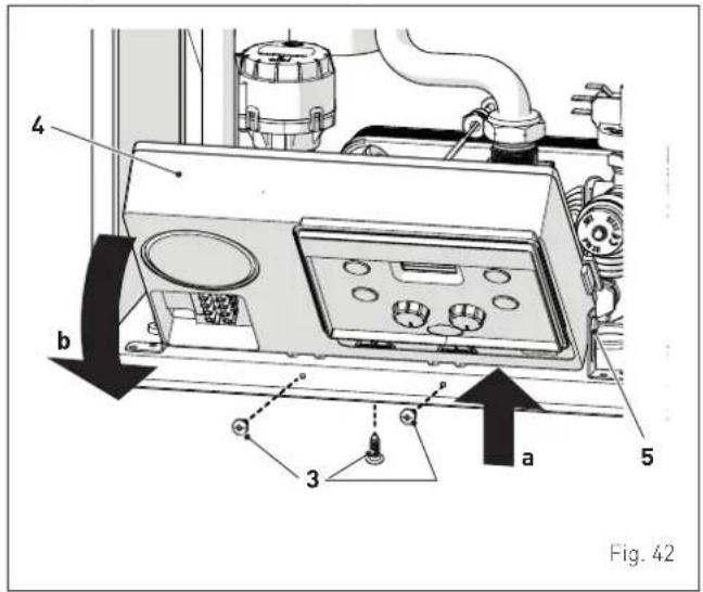
- isolate the gas cock
- loosen the screw of the "mains pressure" point (6) and connect a pressure gauge
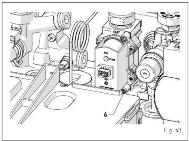
natural_image
Technical line drawing of a mechanical assembly with labeled components (no readable text or symbols)- open the gas cock
- power the boiler by setting the main switch to "ON"
- press the button ⏻ until "SUMMER" mode ⚙ has been selected
- press and hold down the buttonsOK and + at the same time for approximately 10 seconds until the message "Hi" appears on the display together with the flashing symbols and
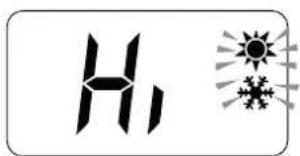
- to dissipate the heat, tun on one or more DHW taps
- press the button+ to make the boiler operate at maximum power "Hi" and check that the mains gas pressure value on the pressure gauge is correct
- disconnect the pressure gauge, carefully close the pressure point (6), test for gas tightness, put the control panel back to the original position and refit the front panel (2). Now conduct a flue gas analysis as detailed in APPENDIX 2
- take a reading of the combustion data and measure the combustion efficiency
- press the button— to make the boiler operate at minimum power "Lo". The message "Lo" will appear on the display together with the flashing symbols 🎨 and 🌐

- take the combustion data reading
- press the button ⏻ to exit the "Chimney sweep Procedure". The boiler water delivery temperature will appear on the display
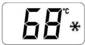
- close the hot water taps that were previously opened
- ensure the required information is recorded in the Gas Boiler System Commissioning Checklist (Benchmark).
Gas supply pressure
| Type of gas G20 G31 | ||
| Pressure (mbar) 20 37 |
NOTE: There are negligible losses of working gas pressure attributable to the boiler as the gas cock is connected directly to the gas valve.
7.7 Gas conversion
MIA-30 can work with G20 or G31 without the need for any mechanical conversion. Simply select parameter "tS 0.3" (see "Parameter setting and display") and set the type of gas to be used, then carry out the entire appliance "Automatic self-calibrating procedure" phase described on page 36.
7.8 Heating power output adjustment
To comply with Building regulations, the heating output must be set according to the requirements of the installed heating system.
This is done by adjustment of "parameter 15" (tS 1.5).
Calculate the heating requirements of the heating system in kW. Determine what that value is, as a % of the nominal heat output of the boiler, see table "Technical features" page 18.
Access the parameters as shown in "Parameter setting and display" page 37, and adjust the parameter 15 (tS 1.5) to that % value
Example:
- Heating system with 8 radiators, average 1.5 kW per radiator total heat
- Requirement 12 kW (8 x 1.5)
- Maximum nominal heat output of boiler = 23.6 kW
- Parameter 15 (tS 1.5) = 12/23.6 = 50.8%. Set tS 1.5 to 51%.

CAUTION
As a condition of the warranty and to ensure correct operation and efficiency, it is important that the boiler is serviced every 12 months, within 30 days of the anniversary of the installation date ensure the required information is recorded in the Gas Boiler System Service Interval Record (page 47) (Benchmark).
8 MAINTENANCE
8.1 Servicing
As a condition of the warranty and to ensure correct operation and efficiency, it is important that the boiler is serviced every 12 months, within 30 days of the anniversary of the installation date ensure the required information is recorded in the Gas Boiler System Service Interval Record (Benchmark).

CAUTION
- Only qualified persons in compliance with the instructions contained in this manual are permitted to install, commission and maintain this boiler. Suitable protective safety equipment MUST be worn. The installation of this boiler must be in accordance with the relevant requirements of the current Gas Safety (installation and use), the local building regulations, and I.E.E. wiring regulations. - Make sure that the system components and pipes are not hot (risk of burning).

WARNING
Before carrying out any interventions described:
- isolate the power supply
- isolate the gas cock
- avoid contact with any hot surfaces.
8.2 External cleaning
8.2.1 Cleaning the case
When cleaning the cladding, use a cloth dampened with soap and water or alcohol for stubborn marks.

DO NOT
Do not use abrasive products.
8.3 Burner Inspection
8.3.1 Burner access
To access the internal parts of the boiler:
- remove the screws (1), pull the front panel (2) forwards and release it from the top by lifting it
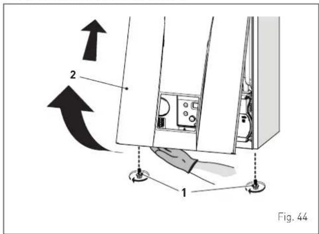
- remove the screws (3) securing the control panel (4)
- move the panel (4) upwards (a) but keeping it in the side guides (5) to the end of travel
- bring it forwards and down (b) until it is horizontal
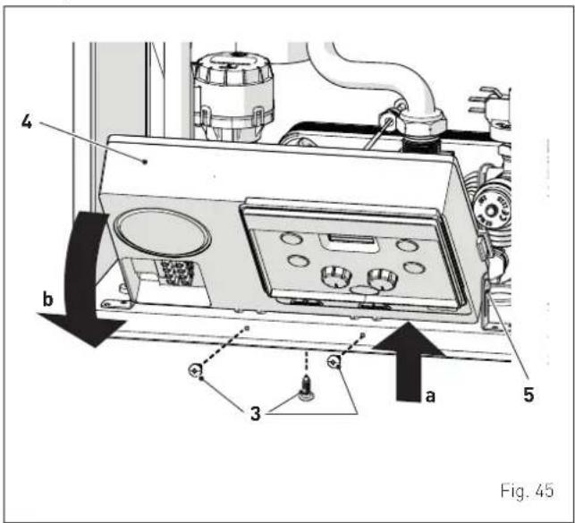
- unscrew the swivel joint (6)
- extract the connectors (7) from the fan and disconnect the electrode cable (8)
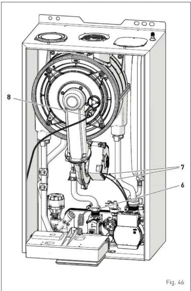
- Unscrew the four nuts (9) securing the combustion chamber door (10)
- pull the fan/sleeve/door unit (11) forwards and remove it
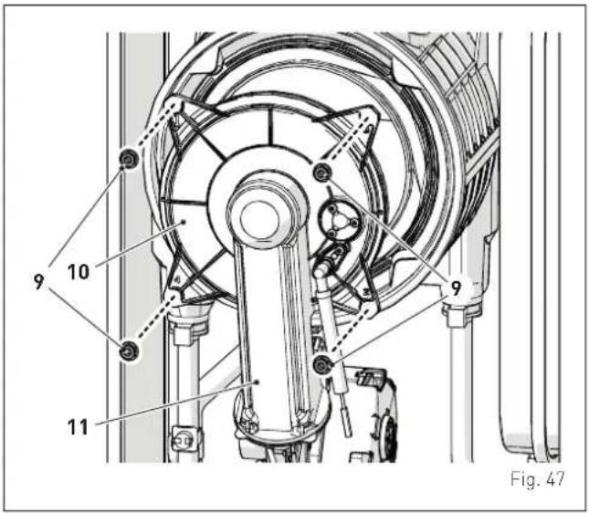

CAUTION
Work carefully when removing the assembly (11) to prevent any damage occurring to the internal insulation of the combustion chamber and the door seal.
- loosen the four nuts (12) securing the fan (13) and remove it.
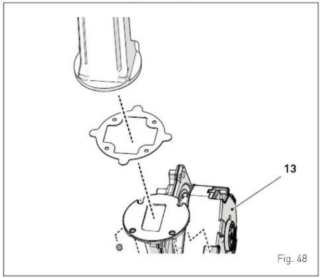
8.3.2 Cleaning the burner and the combustion chamber
The combustion chamber and the burner do not require any particular maintenance. Simply brush them with a soft brush.
8.3.3 Checking the ignition/detection electrode
Check the state of the ignition/detection electrode and replace if necessary. Check the measurements as per the drawing whether the ignition/detection electrode is replaced or not.
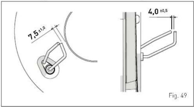
8.3.4 Final operations
After having cleaned the combustion chamber and the burner: - remove any carbon residue
- check that the seal and the insulation of the door (10) to the combustion chamber are undamaged. Replace if necessary
- refit the assembly by carrying out the same operations for removal but in the reverse order and tighten the screws (9) of the door to the combustion chamber
- mount the nozzle (16) back on and adjust it so that the flared part faces downwards, as shown in the figure
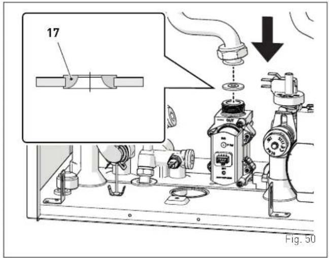
- reconnect the connections to the fan and the electrode.
8.4 Checks
8.4.1 Checking the flue
Check that the flue is undamaged and complete.
8.4.2 Checking the expansion vessel pressure
It is recommended that the expansion vessel on the water side is drained and that the prefilling pressure is not less than 1 bar. If this is not the case, pressurize it to the correct value (see section "Expansion vessel").
Once the checks described above have been completed:
- refill the boiler as described in section "SYSTEM Filling"
- check that the siphon has been filled correctly
- Start the boiler, activate the "Chimney sweep function" and carry out combustion analysis as detailed in Appendix 2
- refit the front panel securing it with the two screws which were removed previously.
8.5 Circuit Board Replacement
Should the circuit board be replace, the engineer MUST set the parameters as indicated in this table and in the sequence shown.
| Type No. | Description | Setting for MIA-30 |
| tS 0.1 | Index showing boiler power in kW1 = 30 | |
| tS 0.2 | Hydraulic configuration0 = combi1 = system2 = N/A3 = N/A4=instant with solar power input5 = open vent | |
| tS 0.3 | Gas Type Configuration0 = G20; 1 = G31 |
To enter "Parameter setting and display" refer to the indications provided in the specific section.
Once the parameters in the table have been set, you must carry out the entire phase of "Automatic self-calibrating procedure" described in the specific section.
If the gas valve and/or the ignition/detection electrode, and/or the burner, and/or the fan are replaced, the engineer must still carry out the entire phase of "Automatic self-calibrating procedure" described in the specific section.
8.6 Malfunction codes and possible solutions
LIST OF MALFUNCTION/FAULT ALARMS
| Type | No. Fault Solution | ||
| AL 01 | Smoke thermostat | - Contact the Technical Assistance Centre | |
| AL 02 | Low water pressure in system | - Restore pressure- Check for any leaks in the system | |
| AL 04 | Domestic hot water sensor fault (return sensor fault for T models) | - Check connections- Check the sensor is working | |
| AL 05 | Delivery sensor (SM) fault | - Check connections- Check the sensor is working | |
| AL 06 | No flame detection | - Check the integrity of the electrode and check that it is not grounded- Check gas availability and pressure- Check the operation of the gas valve | |
| AL 07 | Safety thermostat (TS), intervention | - Check the sensor or thermostat connections- Deaerate the system- Check the bleed valve- Replace the sensor or the thermostat- Check that the pump impeller is not blocked | |
| AL 08 | Fault in the flame detection circuit | - Check the integrity of the electrode and check that it is not grounded- Check the operation of the gas valve | |
| AL 09 | No water circulating in the system | - Check the rotation of the pump rotor- Check the electrical connections- Replace the pump | |
| Type No. Fault Solution | |||
| AL 10 | Auxiliary sensor fault | - Check the hydraulic con-figuration using "tS 0.2"- Check the electrical con-nection | |
| AL 11 | Gas valve modulator disconnected | - Check the electrical con-nection | |
| AL 12 | Domestic hot water sensor fault in tank mode | - Set the parameter tS 0.4 (Combustion configuration) to 0 | |
| AL 13 | Exhaust sensor (SF) intervention | - Check the sensor is working- Replace the smoke probe | |
| AL 14 | Exhaust sensor (SF) fault | - Replace the smoke probe- Check the electrical con-nection of the smoke probe- Contact the Technical Assistance Centre | |
| AL 15 | Fan check cable dis-connected | - Check the connection cable between the fan and the board | |
| AL 18 | Condensate level fault | - Check for any clogging in the pipe which takes the condensate to the siphon- Check that the siphon is not clogged | |
| AL 28 | Maximum number of consecutive resets reached (6) | - Wait 1 hour and try un-blocking the board again- Contact the Technical Assistance Centre | |
| AL 30 | Return sensor fault (boiler sensor fault for T models) | - Replace the return probe- Check parameters- Contact the Technical Assistance Centre | |
| AL 37 | Fault due to low net-work voltage | - Check the voltage- Contact your network provider | |
| AL 40 | Incorrect supply frequency detected | - Contact your network provider | |
| AL 41 | Flame loss more than 6 consecutive times | - Check the ignition/detection electrode- Check the gas supply (open valve)- Check mains gas pressure | |
| AL 42 | Button fault | - Check that buttons are working | |
| AL 43 | Open Therm communi-cation fault | - Check the OT electric connection | |
| AL 44 | No flame valve opening time sum anomaly | - Check for the presence of water hammer on the hot water system and, if present, mount a water hammer arrestor- Check for any abnormal requests on the room thermostat- Contact the Technical Assistance Centre | |
| AL 56 | Lock for ΔT delivery/return over max limit (open vent) | - Contact the Technical Assistance Centre | |
| AL 57 | Lock for flow temper-ature (FT) check (open vent) | - Contact the Technical Assistance Centre | |
| AL 62 | Self-calibrating proce-dure is required | - Carry out the self-calibrating procedure (see the specific section) | |
| AL 72 | Incorrect positioning of the delivery sensor | - Check delivery sensor operation and position | |
| AL 74 | Second delivery sensor fault | - Check second delivery sensor operation and position | |
| AL 77 | EV2 SGV current max/min absolute limits error | - Check gas valve and board | |
| AL 78 | EV2 SGV current upper limit error | - Check gas valve and board | |
| AL 79 | EV2 SGV current lower limit error | - Check gas valve and board | |
| Type | No. Fault Solution | ||
| AL 80 | Fault on the valve control logic line/valve cable damaged | - Check gas valve and board | |
| AL 81 | Lockout due combustion during start-up | - Check for blockage in flue- Check air diaphragm (for BF models)- Check gas calibration- Bleed the air from the gas circuit | |
| AL 82 | Block due to numerous combustion control failures | - Check electrode- Check outlets- Check air diaphragm (for BF models)- Check gas calibration | |
| AL 83 | Irregular combustion (temporary error) | - Check for blockage in flue- Check air diaphragm (for BF models)- Check gas calibration | |
| AL 84 | Flow rate reduced for (presumed) low pressure on mains gas | - Check gas flow rate | |
| AL 88 | Internal error (board component protection) | - Check the board is working- Replace board | |
| AL 89 | Unstable combustion feedback signal error | - Check electrode- Check outlets- Check air diaphragm (for BF models)- Check gas calibration | |
| AL 90 | Combustion set cannot be reached error | - Check electrode- Check outlets- Check air diaphragm (for BF models)- Check gas calibration | |
| ALL 91 | Gas valve out of range - Recalibrate the gas valve | ||
| AL 92 | System has reached maximum air correction error (at the minimum flow rate) | - Check electrode- Check outlets- Check air diaphragm (for BF models)- Check gas calibration | |
| AL 93 | Combustion set cannot be reached error | - Check electrode- Check outlets- Check air diaphragm (for BF models)- Check gas calibration | |
| AL 95 | Flame signal micro interruptions error | - Check electrode- Check board- Check electric power supply- Check gas calibration | |
| AL 96 | Lockout due to flue (exhaust) blockage | - Check for blockage in flue- Check the smoke outlet and electrode position (not touching the burner) | |
| AL 98 | SW error, board start-up | - Contact the Technical Assistance Centre | |
| AL 99 | General board error | - Contact the Technical Assistance Centre | |
| - | - | Frequent relief valve intervention | - Check circuit pressure- Check expansion vessel |
| - | - | Limited production of domestic hot water | - Check the diverter valve- Check that plate heat exchanger is clean- Check domestic hot water circuit valve |
GAS BOILER SYSTEM COMMISSIONING CHECKLIST & WARRANTY VALIDATION RECORD
| Address: | ||||||||||||||||||||
| Boiler make and model: | ||||||||||||||||||||
| Boiler serial number: | ||||||||||||||||||||
| Commissioned by (PRINT NAME): Gas Safe registration number: | ||||||||||||||||||||
| Company name: Telephone number: | ||||||||||||||||||||
| Company email: Company address: | ||||||||||||||||||||
| Commissioning date: | ||||||||||||||||||||
| Heating and hot water system complies with the appropriate Building Regulations? Yes | ||||||||||||||||||||
| Optional: Building Regulations Notification Number (if applicable): | ||||||||||||||||||||
| Time, temperature control and boiler interlock provided for central heating and hot water Yes | ||||||||||||||||||||
| Boiler Plus requirements (tick the appropriate box(s)) | ||||||||||||||||||||
| Boiler Plus option chosen for combination boiler in ENGLAND | Weather compensation Smart thermostat with automisation and optimisation | |||||||||||||||||||
| Load compensation Flue Gas Heat Recovery | ||||||||||||||||||||
| Time and temperature control to hot water Cylinder thermostat and programmer/timer Combination boiler | ||||||||||||||||||||
| Zone valves pre-existing Fitted Not required | ||||||||||||||||||||
| Thermostatic radiator valves pre-existing Fitted Not required | ||||||||||||||||||||
| Automatic bypass to system pre-existing Fitted Not required | ||||||||||||||||||||
| Underfloor heating | pre-existing Fitted Not required | |||||||||||||||||||
| Water quality | ||||||||||||||||||||
| The system has been flushed, cleaned and a suitable inhibitor applied upon final fill, in accordance with BS7593 and boiler manufacturers' instructions Yes | ||||||||||||||||||||
| What system cleaner was used? | Brand: | Product: | ||||||||||||||||||
| What inhibitor was used? | Brand: | Product: | ||||||||||||||||||
| Primary water system filter | pre-existing Fitted Not required | |||||||||||||||||||
| CENTRAL HEATING MODE measure and record (as appropriate) | ||||||||||||||||||||
| Gas rate (for combination boilers complete DHW mode gas rate) | m3/hr | or | ft3/hr | |||||||||||||||||
| Central heating output left at factory settings? | Yes | No | ||||||||||||||||||
| If no, what is the maximum central heating output selected? | kW | |||||||||||||||||||
| Dynamic gas inlet pressure | mbar | |||||||||||||||||||
| Central heating flow temperature | °C | |||||||||||||||||||
| Central heating return temperature | °C | |||||||||||||||||||
| System correctly balanced/rebalanced? Yes | ||||||||||||||||||||
| COMBINATION BOILERS ONLY | ||||||||||||||||||||
| Is the installation in a hard water area (above 200ppm)? | Yes | No | ||||||||||||||||||
| Water scale reducer/softener pre-existing | Fitted | Not required | ||||||||||||||||||
| What type of scale reducer/softener has been fitted? | Brand: | Product: | ||||||||||||||||||
| Water meter fitted? | Yes | No | ||||||||||||||||||
| If yes- DHW expansion vessel | pre-existing | Fitted | Not required | |||||||||||||||||
| Pressure reducing valve | pre-existing | Fitted | Not required | |||||||||||||||||
| DOMESTIC HOT WATER MODE Measure and record | ||||||||||||||||||||
| Gas rate | m3/hr | or | ft3/hr | |||||||||||||||||
| Dynamic gas inlet pressure at maximum rate | mbar | |||||||||||||||||||
| Cold water inlet temperature | °C | |||||||||||||||||||
| Hot water has been checked at all outlets | Yes | Temperature | °C | |||||||||||||||||
| CONDENSATE DISPOSAL | ||||||||||||||||||||
| The condensate drain has been installed in accordance with the manufacturers' instructions and/or BS5546/BS6798 Yes Yes | ||||||||||||||||||||
| Point of termination Internal External (only where internal termination impractical) | ||||||||||||||||||||
| Method of disposal Gravity Pumped | ||||||||||||||||||||
| ALL INSTALLATIONS | ||||||||||||||||||||
| Record the following | At max rate: | CO ppm CO2 % CO/CO2 Ratio | CO ppm CO2 % CO/CO2 Ratio | CO ppm CO2 % CO/CO2 Ratio | CO ppm CO2 % CO/CO2 Ratio | CO ppm CO2 % CO/CO2 Ratio | CO ppm CO2 % CO/CO2 Ratio | CO ppm CO2 % CO/CO2 Ratio | CO ppm CO2 % CO/CO2 Ratio | CO ppm CO2 % CO/CO2 Ratio | CO ppm Co2 % CO/CO2 Ratio | |||||||||
| Where possible, has a flue integrity check been undertaken in accordance with manufacturers' instructions, and readings are correct? Yes | Yes | |||||||||||||||||||
| The operation of the boiler and system controls have been demonstrated to and understood by the customer Yes | Yes | |||||||||||||||||||
| The manufacturers' literature, including Benchmark Checklist and Service Record, has been explained and left with the customer Yes | Yes | |||||||||||||||||||
| Commissioning Engineer's signatureCustomer's signature(To confirm satisfactory demonstration and receipt of manufacturers' literature) | ||||||||||||||||||||
* All installations in England and Wales must be notified to Local Authority Building Control (LABC) either directly or through a Competent Persons Scheme. A Building Regulations Compliance Certificate will then be issued to the customer.
© Heating and Hotwater Industry Council (HHIC)

www.centralheating.co.uk
SERVICE & INTERIM BOILER WORK RECORD
It is recommended that your boiler and heating system are regularly serviced and maintained, in line with manufacturers' instructions, and that the appropriate service / interim work record is completed.
Service provider
When completing a service record (as below), please ensure you have carried out the service as described in the manufacturers' instructions. Always use the manufacturers' specified spare parts.
| SERVICE/INTERIM WORK ON BOILER delete as appropriate | Date: | ||||
| Engineer name: Company name: | |||||
| Telephone N: Gas Safe registration N °: | |||||
| Max rate CO ppm CO 2 % CO/CO 2 | |||||
| Min rate CO ppm CO 2 % CO/CO 2 | |||||
| Where possible, has a flue integrity check been undertaken in accordance with manufacturers' instructions, and readings are correct?° | yes | ||||
| Gas rate: m | 3/h OR ft | 3/h | |||
| Were parts fitted?delete as appropriate Yes No | |||||
| Parts fitted: | |||||
| System inhibitor concentration has been checked and appropriate action taken, in accordance with BS 7593 and boiler manufacturers' instructions. A | yes n/a | ||||
| Comments: | |||||
| Signature: | |||||
*A System inhibitor efficacy test is required on every annual service in accordance with the manufacturers' instructions and BS 7593. It is only acceptable to not have undertaken this if the service engineers attendance visit was in between annual services to attend a non-water facing component.
| SERVICE/INTERIM WORK ON BOILER delete as appropriate | Date: | ||||
| Engineer name: Company name: | |||||
| Telephone N°: Gas Safe registration N | |||||
| Max rate CO ppm CO 2 % CO/CO 2 | |||||
| Min rate CO ppm CO 2 % CO/CO 2 | |||||
| Where possible, has a flue integrity check been undertaken in accordance with manufacturers' instructions, and readings are correct?* | yes | ||||
| Gas rate: m | 3/h OR ft | 3/h | |||
| Were parts fitted? delete as appropriate | Yes No | ||||
| Parts fitted: | |||||
| System inhibitor concentration has been checked and appropriate action taken, in accordance with BS 7593 and boiler manufacturers' instructions. * | yes n/a | ||||
| Comments: | |||||
| Signature: | |||||
*A System inhibitor efficacy test is required on every annual service in accordance with the manufacturers' Instructions and BS 7593. It is only acceptable to not have undertaken this if the service engineers attendance visit was in between annual services to attend a non-water facing component.
| SERVICE/INTERIM WORK ON BOILER delete as appropriate | Date: | ||||
| Engineer name: Company name: | |||||
| Telephone N°: Gas Safe registration N % | |||||
| Max rate CO ppm CO | 2 % CO/CO 2 | ||||
| Min rate CO ppm CO | 2 % CO/CO 2 | ||||
| Where possible, has a flue integrity check been undertaken in accordance with manufacturers' instructions, and readings are correct?" | yes | ||||
| Gas rate: m | 3h OR ft | 3/h | |||
| Were parts fitted?delete as appropriate Yes No | |||||
| Parts fitted: | |||||
| System inhibitor concentration has been checked and appropriate action taken, in accordance with BS 7593 and boiler manufacturers' instructions. * | yes n/a | ||||
| Comments: | |||||
| Signature: | |||||
*A System inhibitor efficacy test is required on every annual service in accordance with the manufacturers' instructions and BS 7593. It is only acceptable to not have undertaken this if the service engineers attendance visit was in between annual services to attend a non-water facing component.
| SERVICE/INTERIM WORK ON BOILER delete as appropriate | Date: | ||||
| Engineer name: Company name: | |||||
| Telephone N: Gas Safe registration N °C | |||||
| Max rate CO ppm CO 2 % CO/CO 2 | |||||
| Min rate CO ppm CO 2 % CO/CO 2 | |||||
| Where possible, has a flue integrity check been undertaken in accordance with manufacturers' instructions, and readings are correct?" | yes | ||||
| Gas rate: m | 3/h OR ft | 3/h | |||
| Were parts fitted?delete as appropriate Yes No | |||||
| Parts fitted: | |||||
| System inhibitor concentration has been checked and appropriate action taken, in accordance with BS 7593 and boiler manufacturers' instructions. * | yes n/a | ||||
| Comments: | |||||
| Signature: | |||||
"A System inhibitor efficacy test is required on every annual service in accordance with the manufacturers' instructions and BS 7593. It is only acceptable to not have undertaken this if the service engineers attendance visit was in between annual services to attend a non-water facing component.
| SERVICE/INTERIM WORK ON BOILER delete as appropriate | Date: | ||||
| Engineer name: Company name: | |||||
| Telephone N°: Gas Safe registration N °C | |||||
| Max rate CO ppm CO 2 % CO/CO 2 | |||||
| Min rate CO ppm CO 2 % CO/CO 2 | |||||
| Where possible, has a flue integrity check been undertaken in accordance with manufacturers' instructions, and readings are correct?" | yes | ||||
| Gas rate: m | 3/h OR ft | 3/h | |||
| Were parts fitted?delete as appropriate Yes No | |||||
| Parts fitted: | |||||
| System inhibitor concentration has been checked and appropriate action taken, in accordance with BS 7593 and boiler manufacturers' instructions. * | yes n/a | ||||
| Comments: | |||||
| Signature: | |||||
*A System inhibitor efficacy test is required on every annual service in accordance with the manufacturers' instructions and BS 7593. It is only acceptable to not have undertaken this if the service engineers attendance visit was in between annual services to attend a non-water facing component.
| SERVICE/INTERIM WORK ON BOILER delete as appropriate | Date: | ||||
| Engineer name: Company name: | |||||
| Telephone N° Gas Safe registration N % | |||||
| Max rate CO ppm CO 2 % CO/CO 2 | |||||
| Min rate CO ppm CO 2 % CO/CO 2 | |||||
| Where possible, has a flue integrity check been undertaken in accordance with manufacturers' instructions, and readings are correct?" | yes | ||||
| Gas rate: m | 3/h OR ft | 3/h | |||
| Were parts fitted?delete as appropriate Yes No | |||||
| Parts fitted: | |||||
| System inhibitor concentration has been checked and appropriate action taken, in accordance with BS 7593 and boiler manufacturers' instructions. * | yes n/a | ||||
| Comments: | |||||
| Signature: | |||||
*A System inhibitor efficacy test is required on every annual service in accordance with the manufacturers' instructions and BS 7593. It is only acceptable to not have undertaken this if the service engineers attendance visit was in between annual services to attend a non-water facing component.
* All installations in England and Wales must be notified to Local Authority Building Control (LABC) either directly or through a Competent Persons Scheme. A Building Regulations Compliance Certificate will then be issued to the customer.
© Heating and Hotwater Industry Council (HHIC)

www.centralheating.co.uk
9 EXPLODED VIEWS
Frame
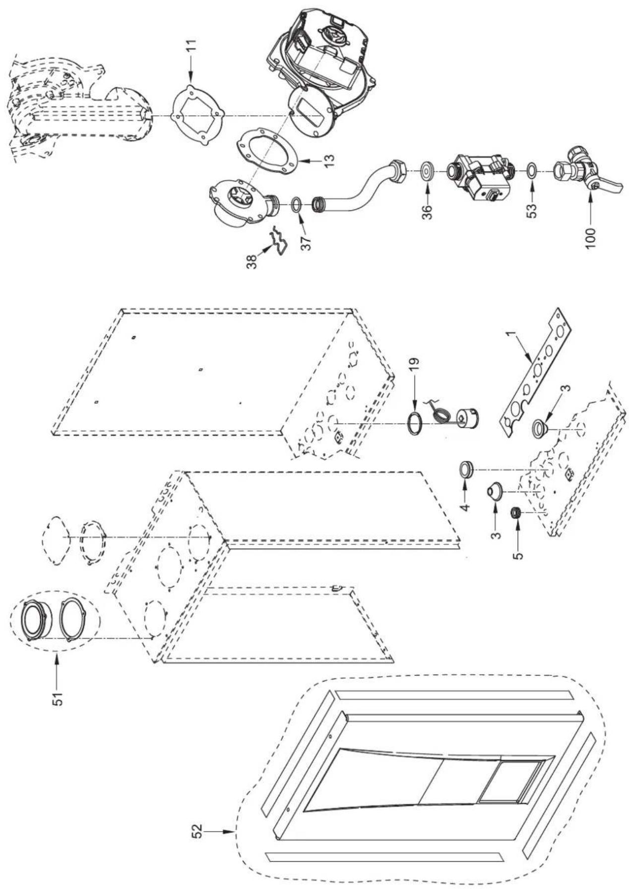
Hydraulic assembly
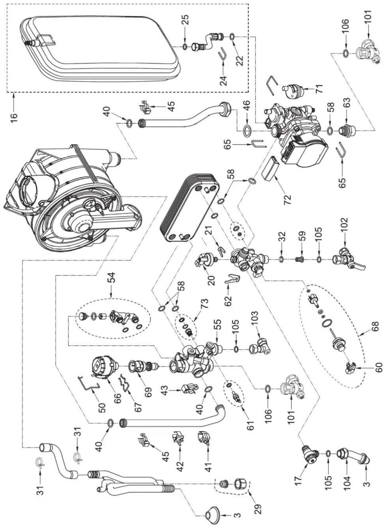
Exchanger / Combustion
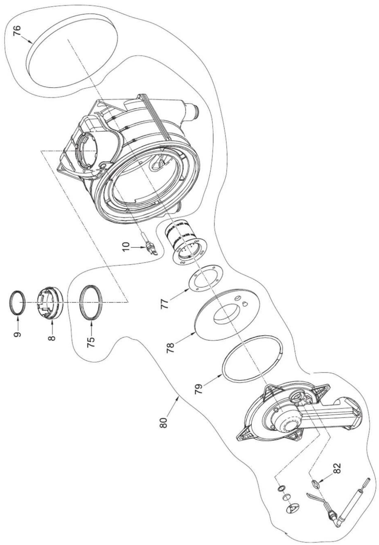
Control panel
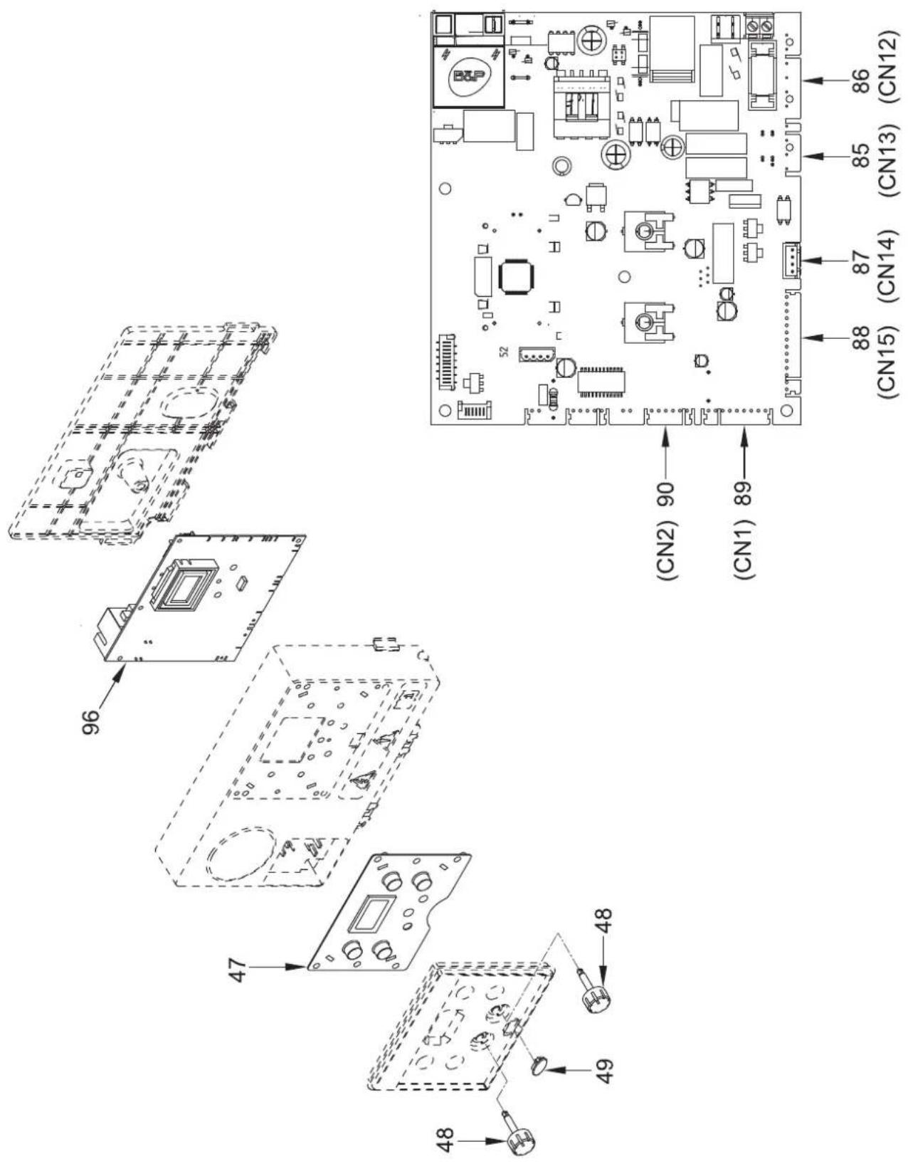
Additional components
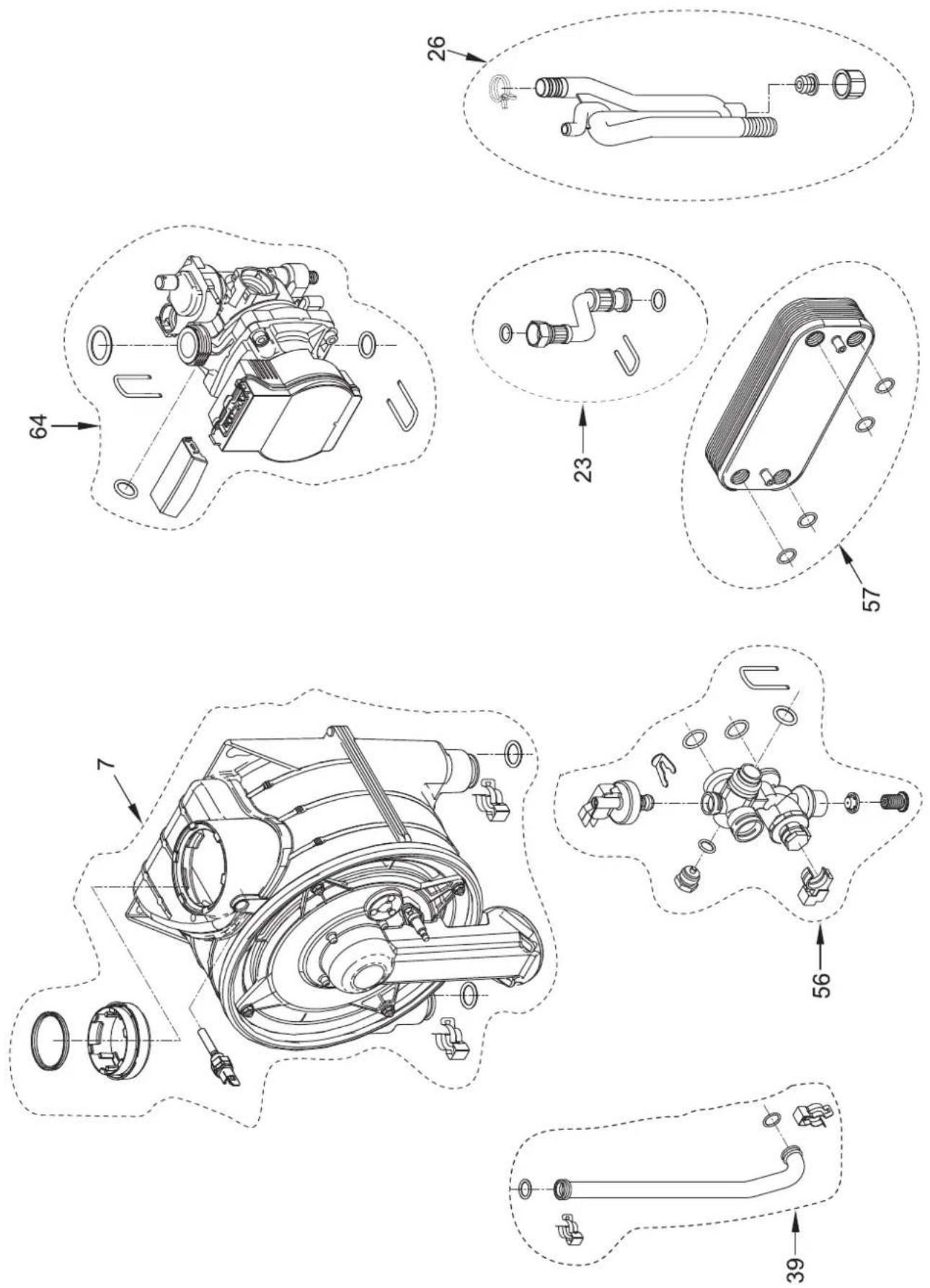
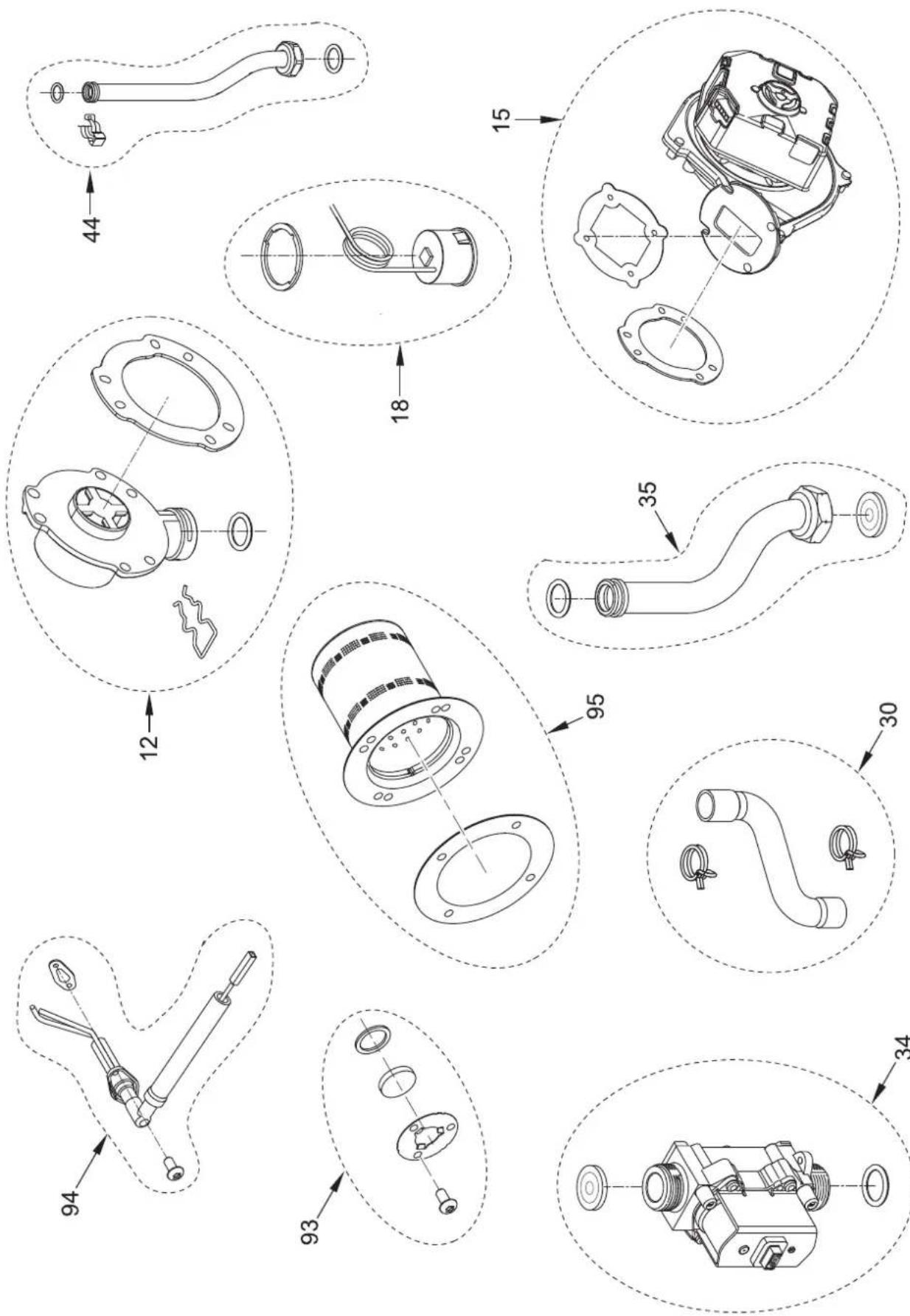
| Pos. | Code Description | Advised parts |
| 001 6 | 229885 Hydraulic group gasket | |
| 002 6 | 226750 Silicone pipe ring øi28 | |
| 003 6 | 226752 Silicone pipe ring øi12 | |
| 004 2 | 214023 Cable-clamp | |
| 005 6 | 226719 Bushing | |
| 007 6 | 281678 Heat exchanger+or+spring C | |
| 008 6 | 296548 Reducer DN 80-60 | |
| 009 6 | 248875 Gasket ∅ 60 | |
| 010 6 | 277130 Probe NTC D.4X40 A | |
| 011 6 | 174816 Gasket for fan flange C | |
| 012 6 | 281750 Group air/gas mixer C | |
| 013 6 | 028716 Gasket for fan/mixer C | |
| 015 6 | 281682 Fan + gasket A | |
| 016 6 | 281673 Expans. vess.+flex+spring C | |
| 017 6 | 040225 Pressure relief valve 1/2" 3 ba | C |
| 018 6 | 281670 Hydrometer + gasket | C |
| 019 6 | 229881 Gasket | |
| 020 6 | 037512 Water pressure switch | B |
| 021 6 | 226639 Spring clip | |
| 022 6 | 226476 ORing diam.15x2 | C |
| 023 6 | 281632 Flex pipe MF3/8" L=200 + or | |
| 024 6 | 226643 Pipe fixing spring | |
| 025 2 | 030226 Gasket ∅ 10,2x14,8x2 | C |
| 026 6 | 281764 Water trap group | C |
| 029 5 | 171635 Cap + gasket for water trap kit | C |
| 030 6 | 281662 Flexible pipe L=210 + spring | C |
| 031 2 | 051150 Clamp diam. 25 | |
| 032 6 | 281442 Water rate adjuster 14 l/min | C |
| 034 6 | 281751 Gas valve+gaskets+instr.sheet | A |
| 035 6 | 281752 Pipe connecting gas valve-mixer | |
| 036 6 | 050469 Nozzle 530 met | |
| 037 6 | 226477 Rubber gasket OR ∅ 17x3 | C |
| 038 6 | 226636 D.H.W. elektrovalve fix.spring | |
| 039 6 | 281675 Flowing pipe C.H.system+or | |
| 040 6 | 226412 O-ring 3068 C | |
| 041 6 | 231372 Temperature sensor | A |
| 042 6 | 146729 100¢C safety stat | A |
| 043 6 | 226601 Spring for heat exchanger conne | |
| 044 6 | 281676 Return pipe C.H.system + or | |
| 045 6 | 226619 Spring for heat exchanger conne | |
| 046 2 | 030267 Piracriten gasket ∅ 30x17x2 | C |
| 047 6 | 305130 Rubber button | |
| 048 6 | 290170 Knob ∅ 20 | |
| 049 6 | 305140 Rubber cap | |
| 050 6 | 226638 Divertor valve motor spring cli | |
| 051 6 | 281674 Group air intake | C |
| 052 6 | 281667 Front panel + insulators | A |
| Pos. | Code Description | Advised parts |
| 053 20 | 030249 Gasket ∅ 24x17x3 | |
| 054 63 | 19653 External by-pass kit C | |
| 055 62 | 65866 C.H. flow manifold | C |
| 056 62 | 81640 C.H. ret.manif+or+wat.pres+filte | C |
| 057 63 | 19690 kit 12 plate heat exchanger + o | C |
| 058 62 | 226475 ORing diam.18,64x3,53 | C |
| 059 62 | 22003 D.H.W. filter | C |
| 060 61 | 131440 Flowmeter sensor B | |
| 061 62 | 281519 Plunged sensor + gasket | A |
| 062 62 | 226645 Spring clip | |
| 063 61 | 120560 Pump nipple 3/4" | |
| 064 62 | 281681 Circulat. pump + gasket | B |
| 065 62 | 226644 Spring clip for rotating connec | |
| 066 60 | 087332 Motor for diverting valve | B |
| 067 | 6226636 D.H.W. elektrovalve fix.spring | |
| 068 63 | 19651 Flowmeter + sensor group | A |
| 069 63 | 19654 Shutter group | C |
| 071 60 | 13182 Automatic air vent C | |
| 072 63 | 19647 Circulateur top cover | |
| 073 62 | 281859 Restraint valve + seeger ring | |
| 075 62 | 248876 Smoke outlet gasket ø80 mm | C |
| 076 63 | 326951 Rear insulation + springs | |
| 077 63 | 326942 Gasket for burner flange | C |
| 078 63 | 326952 Front insulation | |
| 079 63 | 326953 Sealing | |
| 080 63 | 326980 Burner-door group | |
| 082 63 | 326950 Gasket for ignition electrode | C |
| 085 63 | 329482 Pump-fan CN13 connection | |
| 086 63 | 329477 6 pole cable connector CN12 | |
| 087 63 | 323876 4 pole cable connector CN14 | |
| 088 63 | 329473 14 pole cable connector CN15 | |
| 089 63 | 325671 9 pole cable connector CN1 | B |
| 090 63 | 329474 6 pole cable connector CN2 | |
| 093 62 | 281753 Peephole kit | |
| 094 62 | 281754 Ignit.-ionis.elect.+`asket kit | B |
| 095 80 | 76118 Burner + gasket kit | |
| 096 63 | 324931 Main PCB | |
| 100 61 | 177530 Gas cock 3/4" F x 15 | |
| 101 61 | 177505 Ball cock 3/4" x 22 | C |
| 102 61 | 177506 Ball cock 1/2" x 15 | C |
| 103 61 | 142330 Quarter bend 1/2" x 15 | C |
| 104 61 | 157660 Pressure relief valve drain pip | |
| 105 20 | 30227 Gasket ∅ 12x18x2 | |
| 106 20 | 30228 Gasket ∅ 17x24x2 | C |
| 700 52 | 202304 Complete control panel | |
| 701 63 | 316259 5 pole cable connector | B |
| 703 51 | 184817 Fitting cocks kit | C |
10 APPENDIX 1 (GUIDANCE HHIC)
Manufacturers Instructions
Manufacturer's instructions must be followed for the correct connection of the condensate discharge pipe from the boiler as this may vary due to the design of the boiler. For example a visible air break and trap is not required if there is a trap with a minimum condensate seal of 75mm incorporated into the boiler.
Internal Pipe Run In Unheated Spaces
Condensate discharge pipes that are routed in an unheated space such as a loft or garage should be insulated to prevent freezing.
Internal Condensate Pipe Discharge Termination
Internal condensate discharge pipework must be a minimum of 19mm ID (typically 22mm OD) plastic pipe or as per manufacturer's instructions and this should "fall" a minimum of 45mm per metre away from the boiler, taking the shortest practicable route to the termination point. (45mm as per BS6798, 52mm per metre as per industry practice is specified in the following diagrams)
To minimise the risk of freezing during prolonged sub-zero conditions, an internal “gravity discharge point” such as an internal soil stack (preferred method), internal kitchen, utility room or bathroom waste pipe e.g. from a sink, basin, bath or shower should be adopted, where possible.
Note - A suitable permanent connection to the foul waste pipe should be used. Figures 1, 2(a), 2(b) show appropriate connection methods.

HEATING & HOTWATER INDUSTRY COUNCIL
Figure 1 – Connection of condensate discharge pipe to internal soil and vent stack. Note – Check manufacturer's instructions to see if an air break is required.
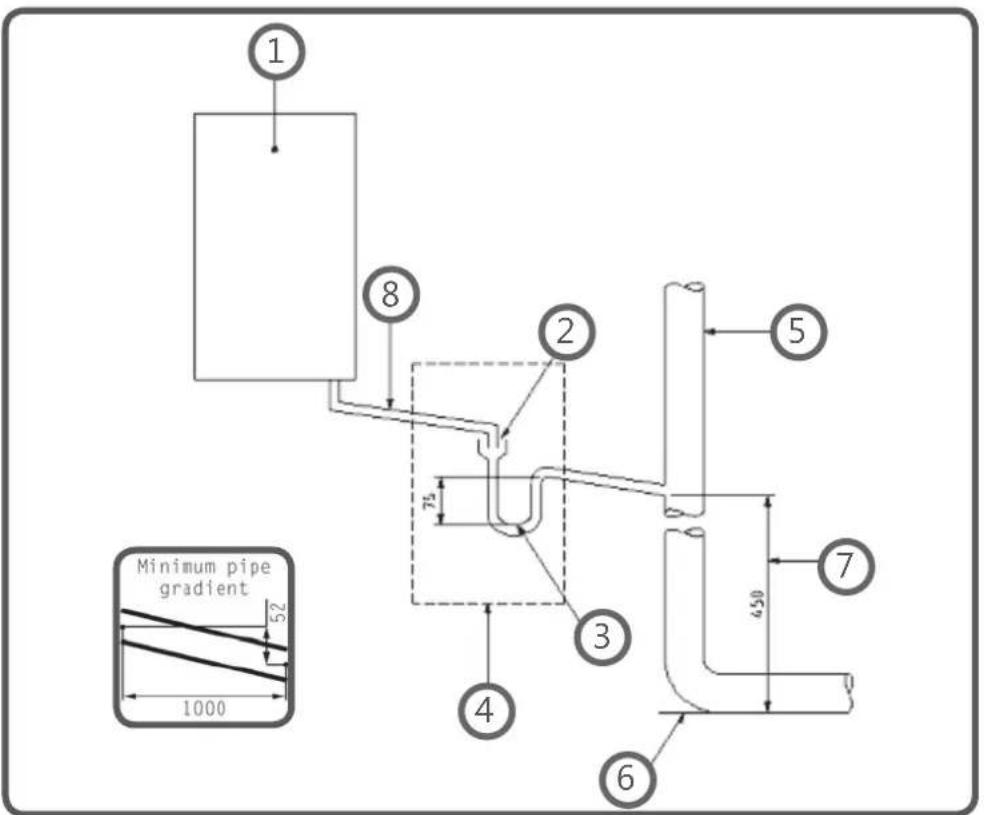
Key
1 Boiler
2 Visible air break
3 75 mm trap
4 Visible air break and trap not required if there is a trap with a minimum condensate seal of 75 mm incorporated into the boiler
5 Soil and vent stack
6 Invert
7 450 mm minimum up to three storeys
8 Minimum internal diameter 19 mm
Internal Condensate Pipe Discharge Termination
Figure 2(a) – Connection of a condensate discharge pipe downstream of a sink, basin, bath or shower waste trap.
Note – Check manufacturer's instructions to see if an air break is required.
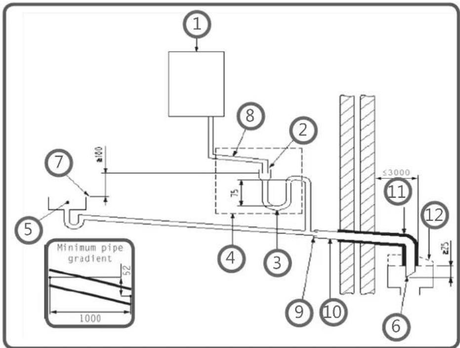
Key
1 Boiler
2 Visible air break
3 75 mm trap
4 Visible air break and trap not required if there is a trap with a minimum condensate seal of 75 mm incorporated into the boiler. In this case the 100 mm is measured to the trap in the boiler.
5 Sink, basin, bath or shower
6 Open end of condensate discharge pipe direct into gully 25 mm min below grating but above water level; end cut at 45°
Note - the maximum external condensate discharge length is 3 metres
7 Sink lip
8 Minimum internal diameter 19 mm
9 Pipe size transition
10 Minimum internal diameter 30 mm
11 Water/weather proof insulation
12 Drain cover/leaf guard
Internal Condensate Pipe Discharge Termination
Figure 2(b) – Connection of a condensate discharge pipe upstream of a sink, basin, bath or shower waste trap
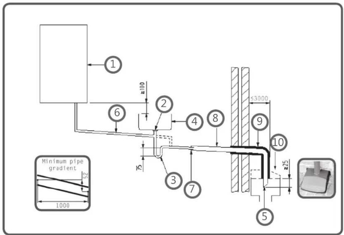
Key
1 Boiler
2 Visible air break at plug hole - alternative connection can be below sink trap
3 75 mm sink, basin, bath or shower waste trap
4 Sink, basin, bath or shower with integral overflow
5 Open end of condensate discharge pipe direct into gully 25 mm min below grating but above water level; end cut at 45°
Note – the maximum external condensate discharge length is 3 metres
6 Minimum internal diameter 19 mm
7 Pipe size transition
8 Minimum internal diameter 30 mm
9 Water/weather proof insulation
10 Fit drain cover/leaf guard

HEATING & HOTWATER INDUSTRY COUNCIL
October 2018 Issue 1.0
Internal Condensate Pipe Discharge Termination
The possibility of waste pipes freezing downstream of the connection point should be considered when determining a suitable connection point - e.g. a slightly longer pipe run to an internal soil stack may be preferable to a shorter run connecting into a kitchen waste pipe discharging directly through the wall to an external drain.
Note - Where "gravity discharge" to an internal termination is not physically possible (e.g. the discharge point is above the appliance location, or access is obstructed by a doorway), or where very long internal pipe runs would be required to reach a suitable discharge point, then a condensate pump should be used.
External waste pipes from kitchens, utility rooms or bathrooms such as sink, basin, and bath or shower waste outlets should be insulated with waterproof UV resistant, class 0 material, terminated below the grid but above the water line and a drain/leaf guard fitted. The waste pipe should be cut at 45 degrees where it terminates into the grid. (See insulation section for guidance on suitable materials).
Condensate Pumps
Use of a Condensate Pump to an Internal Termination
Condensate can be removed using a proprietary condensate pump, of a specification recommended by the boiler or pump manufacturer. In order to minimise the risk of freezing during prolonged sub-zero spells, one of the following methods internal to the property for terminating the boiler condensate pump to a foul water discharge point should be adopted such as an internal soil stack (preferred method), internal kitchen, utility room or bathroom waste pipe such as sink, basin, and bath or shower waste. Figure 3 shows a typical connection method.
October 2018 Issue 1.0

HEATING & HOTWATER INDUSTRY COUNCIL
Internal Condensate Pipe Discharge Termination
Figure 3 – Connection of a condensate pump - typical method (NB manufacturer's detailed instructions should be followed).
Note – Any external pipe work should be insulated, pipe cut at 45 degrees and a drain/ leaf guard fitted.
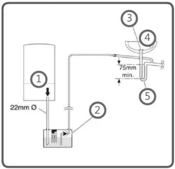
Key
1 Condensate discharge from boiler
2 Condensate pump
3 Visible air break at plug hole
4 Sink or basin with integrated overflow
5 75mm sink waste trap
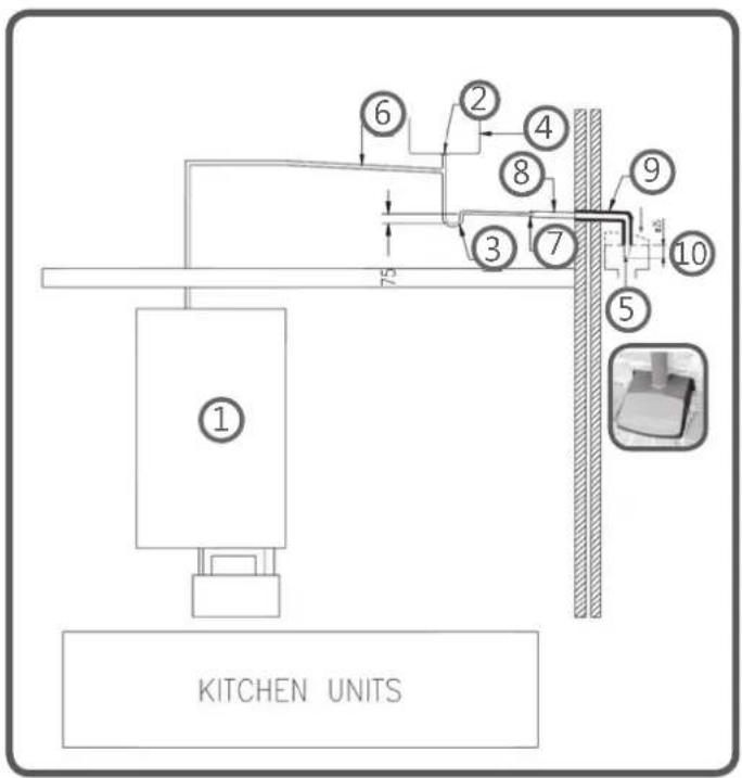
Key
1 Boiler
2 Visible air break at plug hole
3 75 mm sink, basin, bath or shower waste trap
4 Sink, basin, bath or shower with integral overflow
5 Open end of condensate discharge pipe direct into gully 25 mm min below grating but above water level; end cut at 45° Note – the maximum external condensate discharge length is 3 metres
6 Minimum internal diameter 19 mm
7 Pipe size transition
8 Minimum internal diameter 30 mm
9 Water/weather proof insulation
10 Fit drain cover/leaf guard
External Connections
External Connections
Only fit an external boiler condensate drain connection if an internal gravity or pumped connection is impractical to install.
The pipe work from the boiler should be of a minimum 19mm ID or as per manufacturer's instructions and the condensate discharge pipe shall be run in a standard drainpipe material, e.g. poly (vinyl chloride) (PVC), un-plasticized poly (vinyl chloride) (PVC-U), acrylonitrile butadiene-styrene (ABS), polypropylene (PP) or chlorinated poly (vinyl chloride) (PVC-C).
Note - Fixing centres for brackets should be a maximum of 300mm for flexible pipe and 500mm for solid pipe and manufacturer's recommendations should be followed.
The condensate pipe should be run internally as far as possible before going externally and the pipe diameter should be increased to a minimum of 30mm ID (typically 32mm OD) before it passes through the wall. The angle of the pipe should slope downwards by at least 3 degrees as it passes through the wall to assist in maintaining a good velocity as the condensate exits the building.
The external pipe run should be kept as short as possible to a maximum of 3 metres, taking the most direct and "most vertical" route to the discharge point, with no horizontal sections in which condensate might collect.
External Connections
Figure 4 – Connection of condensate discharge pipe to external soil and vent stack
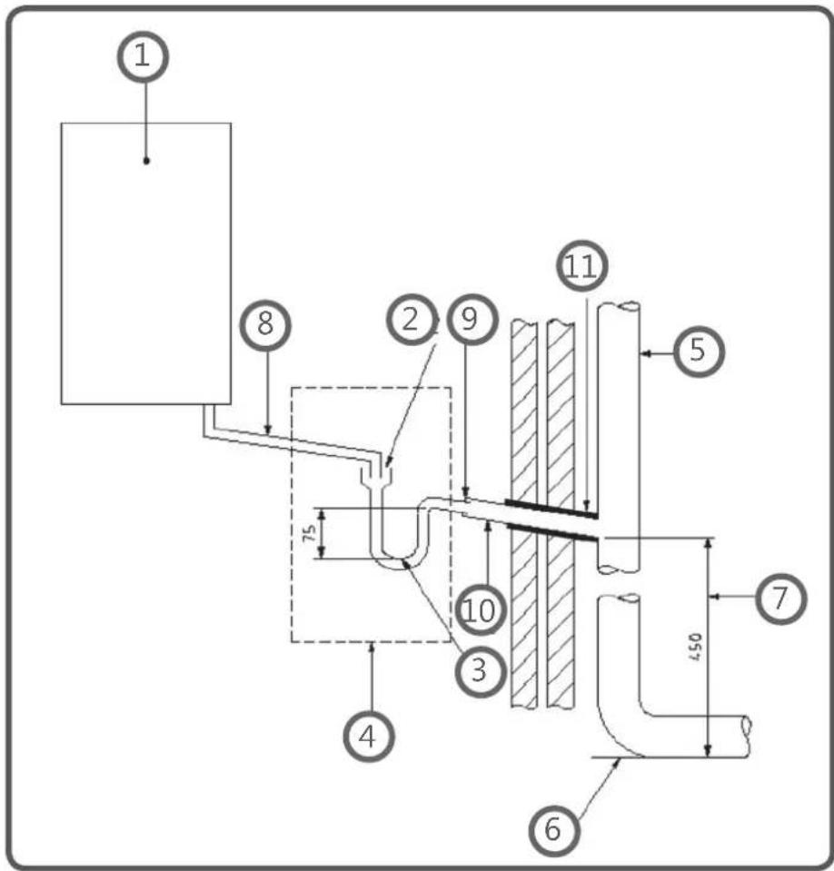
Key
1 Boiler
2 Visible air break
3 75 mm trap
4 Visible air break and trap not required if there is a trap with a minimum condensate seal of 75mm incorporated into the boiler.
5 Soil and vent stack
6 Invert
7 450mm minimum upto three storeys
8 Minimum internal diameter 19 mm
9 Pipe size transition point
10 Minimum internal diameter 30mm
11 Water/weather proof insulation

HEATING & HOTWATER INDUSTRY COUNCIL
October 2018 Issue 1.0
External Connections
Alternative Solutions
Cold weather protection methods approved or endorsed by boiler manufacturers and/or service organisations may be adopted if these are considered suitable by the parties involved. It is the responsibility of the manufacturer of these products to ensure they have completed the necessary testing or calculations to ensure the product offers suitable protection to prevent the condensate pipe from freezing. The product manufacturer should provide information as to what level of external temperature and for what time period the product can protect against sub-zero temperatures, i.e. -15°C for 48 hours. BS6798 refers to devices that pump the condensate produced by a condensing boiler to a fine misting nozzle in the boiler flue terminal so that the condensate is discharged with the hot flue gas. (BS6798 section 6.3.8 note 4). The boiler manufacturer's instructions will provide advice regarding fitting and siting of the flue terminal to ensure safe disposal of the condensate.
Additional Measures
At least one of the following measures should be fitted in addition to the measures detailed above for external condensate discharge pipes
- Insulate external pipe with a minimum thickness of insulation to be 19mm "O" class PVC coated material.
- Fit trace heating – with insulation as recommended by manufacturer.
• Fit internal auxiliary(additional) high volume syphon unit
Auxiliary Syphon – Fitted Internally
Auxiliary siphons fitted inside the premises assist with the siting of the boiler where an external condensate pipe must be fitted. The storage capacity of the auxiliary siphon increases the volume of condensate discharge reducing the risk of freezing. A further reduction in the potential for the pipe to freeze is achieved when combined with the external insulation requirements.

HEATING & HOTWATER INDUSTRY COUNCIL
External Connections
Electric Trace Heating
Trace heating with an external thermostat can be fitted to the external condensate pipe to raise the temperature of the condensate pipe in freezing conditions. Trace heating takes the form of an electrical heating element run in physical contact along the length of the condensate pipe. The pipe is usually covered with thermal insulation to retain heat losses from the pipe. Heat generated by the element then maintains the temperature of the pipe. If such a system is used then the installation instructions of the trace heating manufacturer and any specific recommendations regarding pipe diameter, insulation, etc. should be followed. All other relevant guidance on condensate discharge pipe installation should also be followed.
Insulation Materials
Insulation used for external condensate pipes, sink or washing machine waste pipes should be of class 'O' grade with an outer coating that is weather proof, bird/animal proof, and UV resistant finish. A minimum of 19mm thick insulation is recommended for 32mm external pipes.
Use of Air Breaks In Condensate Discharge Pipes
Heating engineers should follow manufacturer's instructions on the use of air breaks in condensate discharge pipes. A visible air break is not required if the boiler condensate trap has a minimum condensate seal of 75mm incorporated into the boiler.
Connecting to a rain water downpipe/External Soil Stack
When an external soil stack or rain water downpipe is used as the termination (NB only permissible if this downpipe passes to a combined foul and rainwater drainage system) an external air break must be installed between the condensate discharge pipe and the downpipe to avoid reverse flow of rainwater/sewage into the boiler should the downpipe itself become flooded or frozen.
Figure 5 shows a suitable connection method. Pipe insulation should be fitted.
External Connections
Figure 5 – External termination to rainwater downpipe (NB only combined foul/rainwater drain)
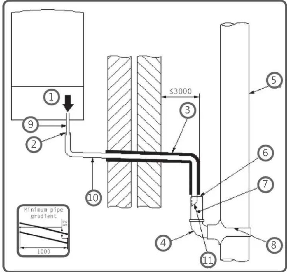
Key
1 Condensate discharge pipe from boiler
2 Pipe size transition point
3 Water/weather proof insulation
4 43mm 90° male/female bend
5 External rain water pipe into foul water
6 External air break
7 Air gap
8 68mm PVCu strap on fitting
9 Minimum internal diameter 19mm
10 Minimum internal diameter 30mm
11 End cut at 45°
External Connections
External Termination of the Condensate Pipe
Where the condensate discharge pipe is terminated over an open foul drain or gully, the pipe should terminate below the grating level, but above water level, in order to minimise “wind chill” at the open end. Pipe drainage and resistance to freezing will be improved if the termination end of the condensate pipe is cut at 45 degrees as opposed to a straight cut.
The use of a drain cover (such as those used to prevent blockage by leaves) must be fitted to offer further protection from wind chill. Figure 6 (following page) shows a suitable connection method. Where the condensate drain pipe terminates in a purpose-designed soakaway (see BS 6798:2014 or boiler installation manual for soakaway design requirements) any above-ground section of condensate discharge pipe should be run and insulated as described above. Figure 7 (following page) shows a suitable connection method.
Unheated Areas in Buildings
Internal condensate drainage pipes run in unheated areas such as lofts, basements and garages should be treated as external connections and insulated accordingly. Weather proof materials may not be necessary and should be assessed by the heating engineer.
Use of Air Breaks In Condensate Discharge Pipes
Installers should follow the manufacturer's instructions on the use of air breaks in condensate discharge pipes. A visible air break and trap is not required if the boiler condensate trap has a minimum condensate seal of 75 mm incorporated into the boiler.
External Connections
Figure 6 – External drain, gully or rainwater hopper
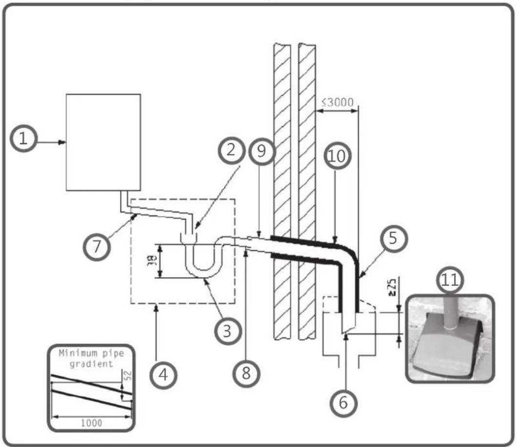
Key
1 Boiler
2 Visible air break
3 38mm minimum trap
4 Visible air break and trap not required if there is a trap with a minimum condensate seal of 38 mm incorporated into the boiler – refer to manufacturers instructions
5 External length of pipe 3 m maximum
6 Open end of condensate discharge pipe direct into gully 25 mm min below grating but above water level; end cut at 45°
7 Minimum internal diameter 19 mm
8 Pipe size transition point
9 Minimum internal diameter 30 mm
10 Water/weather proof insulation
11 Fit drain cover/leaf guard
External Connections
Figure 7 – Example of a purpose made soakaway
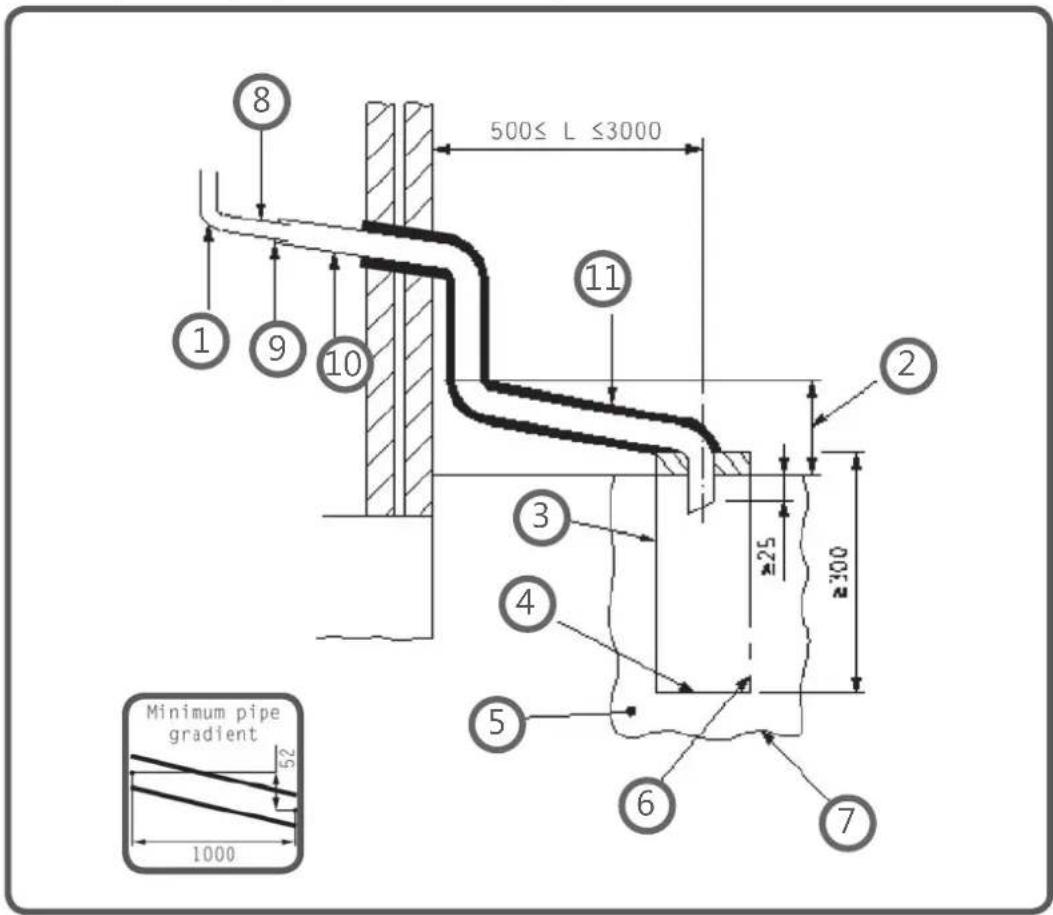
Key
1 Condensate discharge pipe from boiler
2 Ground (this section of the condensate discharge pipe may be run either above or below round level); End cut at 45°
3 Diameter 100 mm minimum plastic tube
4 Bottom of tube sealed
5 Limestone chippings
6 Two rows of three 12 mm holes at 25 mm centres, 50 mm from bottom of tube and facing away from house
7 Hole depth 400 mm minimum by 300 mm diameter
8 Minimum internal diameter 19 mm
9 Pipe size transition point
10 Minimum internal diameter 30 mm
11 Water/weather proof insulation

HEATING & HOTWATER INDUSTRY COUNCIL
October 2018 Issue 1.0
11 APPENDIX 2
FLOWCHART FOR CO AND COMBUSTION RATIO CHECK ON COMMISSIONING A CONDENSING BOILER
PRIOR TO CO AND COMBUSTION RATIO CHECK
The installation instructions should have been followed, gas type verified and gas supply pressure/rate checked as required prior to commissioning.
As part of the installation process, ESPECIALLY WHERE A FLUE HAS BEEN FITTED BY PERSONS OTHER THAN THE BOILER INSTALLER, visually check the integrity of the whole flue system to confirm that all components are correctly assembled, fixed and supported. Check that manufacturer's maximum flue lengths have not been exceeded and all guidance has been followed [e.g. Gas Safe Technical Bulletin TB008].
The flue gas analyser should be of the correct type, as specified by BS 7967
Prior to its use, the flue gas analyser should have been maintained and calibrated as specified by the manufacturer. The installer must have the relevant competence for use of the analyser.
Check and zero the analyser IN FRESH AIR as per analyser manufacturer's instructions.
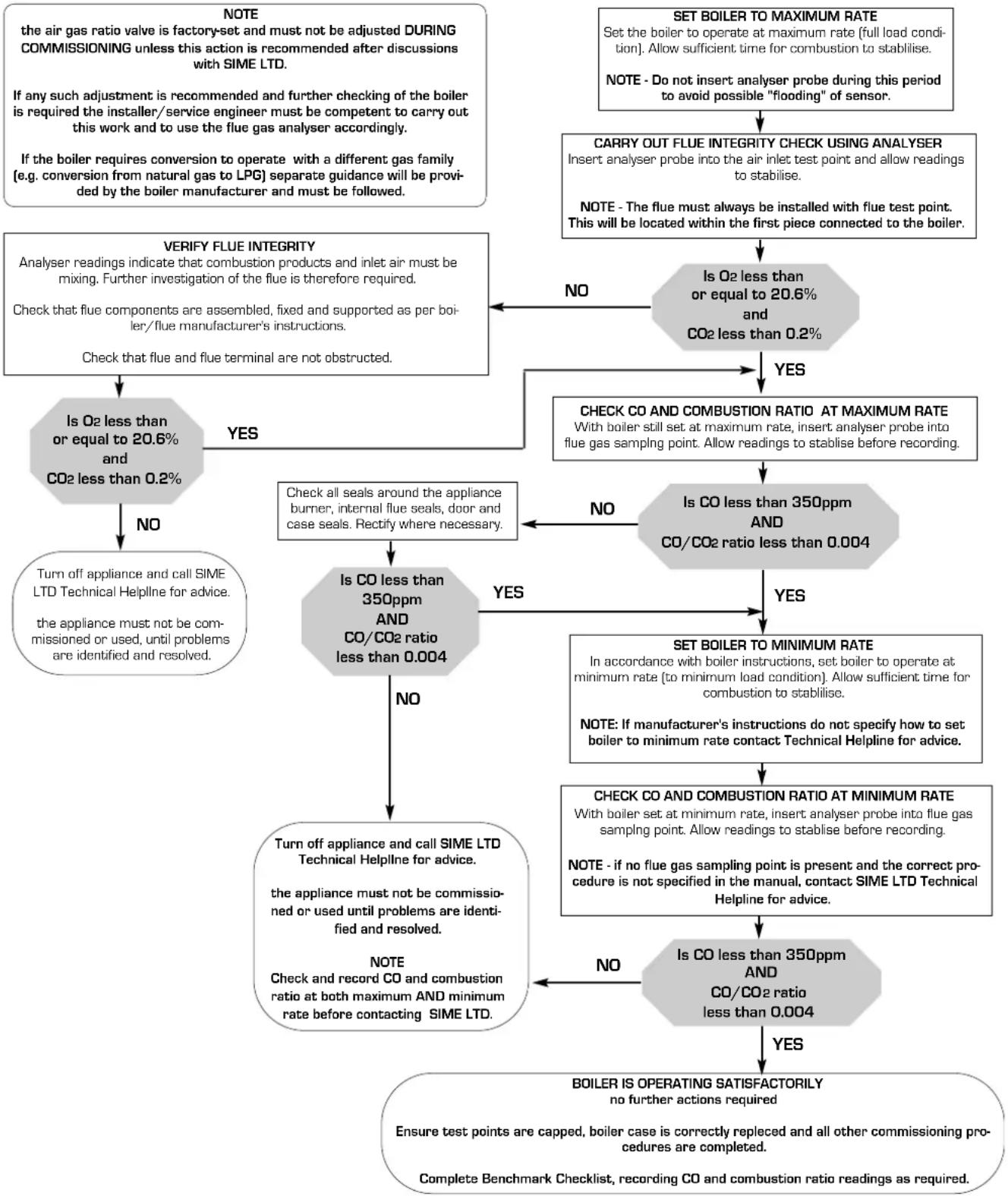
flowchart
graph TD
    A["NOTE\nthe air gas ratio valve is factory-set and must not be adjusted DURING COMMISSIONING unless this action is recommended after discussions with SIME LTD.\nIf any such adjustment is recommended and further checking of the boiler is required the installer/service engineer must be competent to carry out this work and to use the flue gas analyser accordingly.\nIf the boiler requires conversion to operate with a different gas family (e.g. conversion from natural gas to LPG) separate guidance will be provided by the boiler manufacturer and must be followed."] --> B{Is O2 less than or equal to 20.6% and CO2 less than 0.2%}
    B -->|NO| C["Turn off appliance and call SIME LTD Technical Helpline for advice.\nthe appliance must not be commissioned or used, until problems are identified and resolved."]
    B -->|YES| D{Is CO less than 350ppm AND CO/CO2 ratio less than 0.004}
    D -->|NO| E["Turn off appliance and call SIME LTD Technical Helpline for advice.\nthe appliance must not be commissioned or used until problems are identified and resolved.\nNOTE\nCheck and record CO and combustion ratio at both maximum AND minimum rate before contacting SIME LTD."]
    D -->|YES| F["SET BOILER TO MAXIMUM RATE\nSet the boiler to operate at maximum rate [full load condition"]. Allow sufficient time for combustion to stabilise.\nNOTE - Do not insert analyser probe during this period to avoid possible "flooding" of sensor.]
    D -->|YES| G["CHECK CO AND COMBUSTION RATIO AT MAXIMUM RATE\nWith boiler still set at maximum rate, insert analyser probe into flue gas sampling point. Allow readings to stabilise before recording."]
    D -->|NO| H["Is CO less than 350ppm AND CO/CO2 ratio less than 0.004"]
    H --> I["SET BOILER TO MINIMUM RATE\nIn accordance with boiler instructions, set boiler to operate at minimum rate [to minimum load condition"]. Allow sufficient time for combustion to stabilise.\nNOTE: If manufacturer's instructions do not specify how to set boiler to minimum rate contact Technical Helpline for advice.]
    H -->|YES| J["CHECK CO AND COMBUSTION RATIO AT MINIMUM RATE\nWith boiler set at minimum rate, insert analyser probe into flue gas sampling point. Allow readings to stabilise before recording.\nNOTE - if no flue gas sampling point is present and the correct procedure is not specified in the manual, contact SIME LTD Technical Helpline for advice."]
    J --> K["Is CO less than 350ppm AND CO/CO2 ratio less than 0.004"]
    K --> L["BOILER IS OPERATING SATISFACTORILY\nno further actions required\nEnsure test points are capped, boiler case is correctly replaced and all other commissioning procedures are completed.\nComplete Benchmark Checklist, recording CO and combustion ratio readings as required."]
    B -->|NO| M["Is O2 less than or equal to 20.6% and CO2 less than 0.2%"]
    M --> N["VERIFY FLUE INTEGRITY\nAnalyser readings indicate that combustion products and inlet air must be mixing. Further investigation of the flue is therefore required.\nCheck that flue components are assembled, fixed and supported as per boiler/flue manufacturer's instructions.\nCheck that flue and flue terminal are not obstructed."]
    M -->|NO| N
12 PRODUCT DATA SHEET
 | |
| MIA-30 | |
| D.H.W load profile declared | XL |
| C.H. energy efficiency class |  |
| D.H.W. energy efficiency class |  |
| Heat output (kW) | 24 |
| C.H. annual energy consumption (GJ) | 44 |
| D.H.W. annual combustible consumption (GJ) | 17 |
| C.H. seasonal energy efficiency (%) | 93 |
| D.HW. energy efficiency (%) | 86 |
| Sound power dB(A) | 57 |
| Specific precautionary measures to be adopted at the time of assembly, installation or maintenance of the equipment are contained in the boiler instruction manualConforming to Annex IV (item 2) of the Delegated Regulations (EU) No. 811/2013 which supplements Directive 2010/30/EU | |
13 ANNEX AA.1
| Information requirements for boiler space heaters, boiler combination heaters | ||||||||
| Model(s): MIA-30 | ||||||||
| Condensing boiler: Yes | ||||||||
| Low-temperature boiler: Yes | ||||||||
| B11 boiler: No | ||||||||
| Cogeneration space heater: No Equipped with a supplementary heater: No | ||||||||
| Combination heater: Yes | ||||||||
| Item | Symbol | Value | Unit | Item | Symbol | Value | Unit | |
| Nominal heat output for space heating | P_n | 24 | kW | Seasonal space heating energy efficiency | ns | 93 | % | |
| For boiler space heaters and boiler combination heaters: useful heat output | For boiler space heaters and boiler combination heaters: useful efficiency | |||||||
| At nominal heat output and high-temperature regime* | P_6 | 23,6 | kW | At nominal heat output and high-temperature regime (*) | n4 | 87,9 | % | |
| At 30% of nominal heat output and low-temperature regime* | P_1 | 7,8 | kW | At 30% of nominal heat output and low-temperature regime (*) | n1 | 97,7 | % | |
| Auxiliary electricity consumption | Other items | |||||||
| At full load | el_mex | 0,043 | kW | Standby heat loss | Pstby | 0,082 | kW | |
| At part load | el_min | 0,012 | kW | Ignition burner power consumption | Pign | 0 | kW | |
| In standby mode | PSB | 0,004 | kW | Emissions of nitrogen oxides | NOx | 37 | mg/kWh | |
| For combination heaters: | ||||||||
| Declared load profile | XL | Water heating energy efficiency | nwh | 86 | % | |||
| Daily electricity consumption Qelec | 0,123 | kWh | Daily fuel consumption | Qfuel | 22,555 | kWh | ||
| Contact details Fonderie S.p.A. Via Garbo 27, 37045 Legnago (VR) ITALIA | ||||||||
| a. High-temperature regime means 60°C return temperature at heater inlet and 80°C feed temperature at heater outlet.b. Low-temperature regime means for condensing boilers 30°C, for low-temperature boilers 37°C and for other heaters 50°C return temperature. (*) The yield data have been calculated using the higher heating value. | ||||||||
sime
Sime Ltd
1a Blue Ridge Park
Thunderhead Ridge
Glasshoughton, Castleford, WF10 4UA
Phone: 0345 901 1114
Fax: 0345 901 1115
www.sime.co.uk
Email: enquiries@sime.co.uk
- Condensing sealed wall-mounted boiler
- MIA-30
- USER, INSTALLATION AND SERVICING INSTRUCTIONS
- IMPORTANT NOTICE
- SAFE HANDLING
- WARNING
- NOTICE
- Code Of Practice
- Standards of Work
- Customer Service
- The Benchmark Scheme
- Important Information
- COMPLIANCE
- SYMBOLS
- ELECTRICAL HAZARD
- DO NOT
- CAUTION
- MANUAL STRUCTURE
- USER INSTRUCTIONS
- DESCRIPTION OF THE APPLIANCE
- INSTALLATION AND SERVICING INSTRUCTIONS
- WARNINGS
- TABLE OF CONTENTS
- USING THE BOILER MIA-30 10
- SHUTDOWN 12
- MAINTENANCE 13
- DISPOSAL 13
- VERY IMPORTANT!
- USING THE BOILER MIA-30
- Control panel
- KNOBS
- FUNCTIONAL BUTTONS
- DISPLAY
- Preliminary checks
- Ignition
- Adjusting the delivery temperature
- Adjusting the domestic hot water temperature
- Fault / malfunction codes
- SHUTDOWN
- Temporary shutdown
- Shutting down for long periods
- MAINTENANCE
- Servicing
- External cleaning
- Cleaning the case
- DISPOSAL
- Disposal of the equipment (European Directive 2012/19/EU)
- DESCRIPTION OF THE APPLIANCE 16
- DESCRIPTION OF THE APPLIANCE
- Characteristics
- Check and safety devices
- Identification
- Structure
- KEY:
- Sensors
- Correspondence of Temperature Detected/Resistance
- Expansion vessel
- Circulation pump
- Control panel
- Wiring diagram
- Installer must:
- Installer Checklist
- Has the pump been rotated manually?
- Has the D.H.W. flow rate been set to the customer requirements?
- INSTALLATION 26
- COMMISSIONING 36
- MAINTENANCE 42
- EXPLODED VIEWS 48
- APPENDIX 1 (GUIDANCE HHIC) 55
- APPENDIX 2 69
- PRODUCT DATA SHEET 70
- ANNEX AA.1 71
- sime 6 INSTALLATION
- Receiving the product
- Dimensions and weight
- Handling
- Ventilation requirements
- New installation or installation of a replacement appliance
- Cleaning the system
- Characteristics of feedwater and system treatment
- Boiler installation
- Plumbing connections
- Plumbing accessories (optional)
- Condensate outlet/collection
- Gas supply
- Connecting the flue
- Flue Terminal Positions
- Installation of coaxial flues 60/100mm - 80/125mm
- IMPORTANT:
- HORIZONTAL FLUES MUST BE LEVEL
- LIST OF 60/100 ACCESSORIES
- LIST OF 080/125 ACCESSORIES
- Installation of separate ducts 80mm
- NOTE
- Plug/socket for attaching the air inlet pipe (separate ducts)
- Electrical connections and External controls
- External temperature sensor
- Climatic curve
- External timers and Room Thermostats
- EXAMPLE of use of the command/control device on some types of heating systems
- ONE DIRECT ZONE system, external sensor and room thermostat.
- MULTI ZONE system - with zone valve, room thermostat and external sensor.
- MULTI ZONE system - with pump, room thermostat and external sensor.
- Refilling or emptying
- Method of filling a sealed system
- SYSTEM Filling
- Remove the front panel:
- Domestic hot water circuit:
- Heating circuit:
- EMPTYING operations
- Boiler:
- Preliminary operations
- Before commissioning
- Automatic self-calibrating procedure
- Parameter setting and display
- List of parameters
- Display of operating data and counters
- Checks
- Chimney sweep function
- sime
- Gas conversion
- Heating power output adjustment
- Example:
- MAINTENANCE
- Servicing
- External cleaning
- Cleaning the case
- Burner Inspection
- Burner access
- Cleaning the burner and the combustion chamber
- Checking the ignition/detection electrode
- Final operations
- Checks
- Checking the flue
- Checking the expansion vessel pressure
- Circuit Board Replacement
- Malfunction codes and possible solutions
- SERVICE & INTERIM BOILER WORK RECORD
- Service provider
- EXPLODED VIEWS
- Control panel
- APPENDIX 1 (GUIDANCE HHIC)
- Manufacturers Instructions
- Internal Condensate Pipe Discharge Termination
- Key
- Condensate Pumps
- Use of a Condensate Pump to an Internal Termination
- External Connections
- Alternative Solutions
- Additional Measures
- Auxiliary Syphon – Fitted Internally
- Electric Trace Heating
- Insulation Materials
- Use of Air Breaks In Condensate Discharge Pipes
- Connecting to a rain water downpipe/External Soil Stack
- External Termination of the Condensate Pipe
- Unheated Areas in Buildings
- APPENDIX 2
- PRIOR TO CO AND COMBUSTION RATIO CHECK
- PRODUCT DATA SHEET
- ANNEX AA.1
- Sime Ltd
Brand : SIME
Model : MIA-30
Category : Water heaters and boilers