
10A18-4C - Electronic board Daytronic - Free user manual and instructions
Find the device manual for free 10A18-4C Daytronic in PDF.


| Product Type | Signal Conditioning Module |
| Model | 10A18-4C |
| Brand | Daytronic |
| Number of Channels | 4 |
| Input Type | Analog Voltage/Current |
| Output Type | Analog or Digital (depending on configuration) |
| Power Supply | +15V to +24V DC, 200 mA |
| Dimensions (W x H x D) | 4.5 x 1.5 x 6.0 inches (114 x 38 x 152 mm) |
| Weight | 0.5 lbs (0.23 kg) |
| Operating Temperature | 0 to 50 °C |
| Storage Temperature | -20 to 70 °C |
| Signal Isolation | 1500 Vrms |
| Bandwidth | 10 kHz |
| Input Impedance | 1 MΩ |
| Output Range | ±10 V |
| Accuracy | ±0.1% of full scale |
| Protection Features | Overvoltage, reverse polarity, short-circuit |
| Mounting | Panel mount or DIN rail |
| Connection | Screw terminals |
| Maintenance | Clean with dry cloth; no user-serviceable parts |
| Safety | Follow ESD precautions; disconnect power before servicing |
| Spare Parts | Contact Daytronic or authorized distributor |
| Warranty | 1 year limited warranty |
| Compliance | CE, RoHS |
Frequently Asked Questions - 10A18-4C Daytronic
User questions about 10A18-4C Daytronic
0 question about this device. Answer the ones you know or ask your own.
Ask a new question about this device
Download the instructions for your Electronic board in PDF format for free! Find your manual 10A18-4C - Daytronic and take your electronic device back in hand. On this page are published all the documents necessary for the use of your device. 10A18-4C by Daytronic.
USER MANUAL 10A18-4C Daytronic
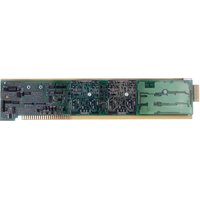
The Model 10A18-4C is a high-bandwidth conditioner card designed for temperature measurement using 100- Ω platinumResistance Temperature Detectors (RTD's) of either DIN (European) or American design.* It produces an output voltage that is linearly related to actual temperature instead of resistance—with selectable accuracy (depending on the operating measurement range) of up to ±0.2° C (see Fig. 1). Since the 10A18-4C provides its own per-channel temperature curve fitting, no further system-level linearization is required.
Precision constant-current excitation is provided for four independent sensor channels, which may be intermixed as required. RTD inputs are normally set for four-wire cabling, with nominal excitation of one milliampere and input impedance exceeding 10 MΩ, to eliminate common self-heating and cable-loading errors. However, for an RTD channel with a shared “+SIGNAL” and “+CURRENT” line, three-wire mode is available, if desired, via an internal jumper setting (as explained in Section 3.a, below).
ADDITIONAL 10A18-4C SPECIFICATIONS
RTD Types: Platinum; DIN (European) or American standard with "ice-point" of 100 ohms(ONLY)
Linear Range and Accuracy: -200.0°C to +600.0°C full-scale for each RTD standard (DIN and American); accuracy of linearization will depend on the selected RTD standard and the selected operating range (see Fig. 1, which shows worst-case error that could occur for a 10A18-4C card operating at an ambient temperature of 25° ± 10° C, six months after calibration)**; automatically selected—on an individual channel basis—when the channel is configured; System 10 channel “type” codes assigned to 10A18-4C data channels are given in Table 2, Section 3.b, below
Excitation (per channel): Nominal 1 mA
Amplifier (per channel): Low-drift, linearized by current feedback
Normal-Mode Range: ±350 mV operating; ±5 V without instrument damage
(cont'd)
* F or the 10A18-4C, "American" standard conforms to NIST "Reference Function."
** With proper calibration, each operating range can be expressed, if desired, in degrees Fahrenheit (see Section 3.b). Note that the expected linearity deviation for most temperature measurements within the 10A18-4C's full -200°C to +600°C range are substantially less than the maximum error values given in Fig. 1. More detailed information is available on request from the Daytronic factory, if error reduction below the limits shown in Fig. 1 is desired. Note also that, while measurement accuracy is independent of the system using the 10A18-4C card, final measurement resolution will, in general, depend on the system. In System 10, the resolution is limited by the readout to a maximum resolution of approximately one part in 30,000 (e.g., ± 0.01°C for measurements up to 300°C ).
Common-Mode Range (expressed as lead-wire resistance rejection, 100 Ω maximum) 0.004%/Ω (4-wire)
Input Impedance (Differential): Greater than 10 MΩ
Offset: Initial: ±5 μV; vs. Temperature: ±0.2 μV/°C; vs. Time: ±1 μV/month
Gain Accuracy: ±0.02% of full scale
Gain Stability: vs. Temperature: ±25 ppm/°C; vs. Time: ±20 ppm/month
Filter (per channel): 3-pole modified Butterworth; 3 dB down at 10 Hz; 60 dB down at 190 Hz
Step-Response Settling Time (Full-Scale Output):
To 1% of final value: 65 msec
To 0.1% of final value: 85 msec
To 0.02% of final value: 100 msec
Fig. 1 Range-Dependent Accuracy of the Model 10A18-4C

Fig. 1(a) For DIN Standard Platinum RTD's (α=0.00385)

Fig. 1(b) For American Standard Platinum RTD's ( α0=0.00392 )
Outputs: 10.000 mV/°C for DIN-standard transducers; 10.218 mV/°C for American-standard transducers
Auxiliary Outputs: Filtered outputs available on mainframe wire-wrap pins
2 TRANSDUCER CONNECTIONS
The Model 10A18-4C's I/O CONNECTOR mates with Daytronic CONDITIONER CONNECTOR No. 60322, shown in Fig. 1.5 (in Manual Section 1.E.1). Standard four-wire RTD cabling is shown in Fig. 2(a), below. With separate excitation and sense lines, this mode of cabling normally yields the highest measurement accuracy. However, any 10A18-4C input channel can be set to accommodate the alternative three-wire cabling shown in Fig. 2(b). THE APPROPRIATE JUMPER SETTING MUST BE MADE FOR EACH 10A18-4C CHANNEL, DEPENDING ON WHETHER 4-WIRE OR 3-WIRE Cabling IS BEING USED FOR THAT CHANNEL (see the instructions in Section 3.a, below). Table 1 gives standard pin assignments for the I/O Connector.
IMPORTANT: When cabling the 10A18-4C, you can ensure static protection by connecting the SHIELD wire to Pin 10 as well as to the connector ground lug, as shown in Fig. 2.
Fig. 2 Model 10A18-4C Transducer Cabling


Table 1 Model 10A18-4C Pin Assignments
| I/O Connector Conditioner Conditioner Pin Channel Line Number Number Function | ||
| 1 | 1 | +SIGNAL |
| A | 1 | -SIGNAL |
| 2 | 1 | +CURRENT |
| B | 1 | -CURRENT |
| 3 | 2 | +SIGNAL |
| C | 2 | -SIGNAL |
| 4 | 2 | +CURRENT |
| D | 2 | -CURRENT |
| 5 | 3 | +SIGNAL |
| E | 3 | -SIGNAL |
| 6 | 3 | +CURRENT |
| F | 3 | -CURRENT |
| 7 | 4 | +SIGNAL |
| H | 4 | -SIGNAL |
| 8 | 4 | +CURRENT |
| J | 4 | -CURRENT |
| 10 SHIELD9,K,L Not Committed | ||
3
SETUP AND/OR OPERATING CONSIDERATIONS
3.a SETTING A 10A18-4C CHANNEL FOR FOUR-WIRE OR THREE-WIRE RTD CABLING
When the Model 10A18-4C is shipped, all four channels are normally set for the four-wire RTD cabling shown in Fig. 1(a), above, since this mode of cabling normally yields the highest accuracy. If you wish to use the three-wire cabling shown in Fig. 1(b) for a given 10A18-4C channel, you should
- Remove the 10A18-4C card from its mainframe slot. For "Card Insertion and Removal," see Manual Section 1.B. Since the 10A18-4C is "hot-pluggable," you need NOT turn off mainframe power before removing the card.
- Refer to Fig. 3, below, and locate the four sets of "RTD CABLING" PROGRAMMING JUMPER PINS, one for each channel, on the top (component) side of the card. One "minijumper" is provided for each channel, for interconnecting any two adjacent jumper pins.
- Position the jumper for each active channel as shown in Fig. 3 to set the desired wiring mode for that channel.
- Reinsert the 10A18-4C card into its mainframe slot.
3.b CONFIGURATION AND CALIBRATION
For initial configuration of ANALOG INPUT CHANNELS dedicated to a specific Model 10A18-4C card when used in System 10, see the following section, along with the general remarks on System 10 "real-channel" configuration in Manual Section 1.G.1 and elsewhere in the System 10 Guidebook.
CALCULATED CALIBRATION
In System 10, the initial configuration and CALCULATED CALIBRATION of a 10A18-4C channel (No. "x") involve direct entry of the channel's TYPE CODE, SCALING FACTOR ("m" coefficient), and ZERO OFFSET ("b" term) via the corresponding mnemonic commands. The values of these parameters that are entered will depend on the RTD type, range, and desired engineering units (°C or °F), as given in Table 2, below. For
Fig. 3 10A18-4C "RTD CABLING" Programming Jumper Pins

increased accuracy, you may perform a subsequent TWO-POINT (DEADWEIGHT) calibration of a 10A18-4C channel in System 10, as explained below.*
In the following procedure, Channel No. "x" is a System 10 "REAL CHANNEL" sourced by a 10A18-4C card. Note that, with the exception of the LOCATE (LCT) command (Step 2), each of the commands can be applied to a continuous range of channels by entering the command in "range" form, where the single channel-number argument "x" is replaced by "x TO y" (indicating all channels from Channel No. x to and including Channel No. y).
- Turn ON the system EEPROM SWITCH.
- Make sure that Channel No. x has been assigned the proper A-SLOT / SUBCHANNEL "location." See Manual Section 1.G.2 for details on the LOCATE (LCT) command.
- Apply a RESET (RST) command to Channel No. x:
RST x [CR]
The channel will be retyped as "55" (i.e., a direct millivolt reading from the system's internal Called Signal Bus). Its SCALING FACTOR ("m") will be changed to "5000" and its ZERO OFFSET ("b") to "0." Its current "location" (LCT) assignment will not be affected.
- Apply the following commands to Channel No. x, using the values of "v," "m," and "b" given in Table 2 for the channel's specific TC type and range:
TYP x = v [CR]
EMMx = m [CR]
BEE x = b [CR]
Be sure to enter the “m” value as shown (with a “0” or “00” after the decimal point), if you want your measurement readout to be in tenths or hundredths of a degree, respectively.
Table 2 Calibration Values for a 10A18-4C Channel
| RTD Standard Range & Resolution ("v") ("m") ("b") | ype Code Scaling Factor Zer | |||
| DIN -200.0°C to +600.0°C 72 | 500.0 | 0.0 | ||
| DIN -200.00°C to +300.00°C | 71 | 250.00 | 0.00 | |
| DIN -328.0°F to +1112.0°F | 72 | 900.0 | 32.0 | |
| DIN -250.00°F to +250.00°F | 70 | 225.00 | 32.00 | |
| American -200.0°C to +600.0°C | 72 | 489.4 | 0.0 | |
| American -200.00°C to +300.00°C | 71 | 244.88 | 0.00 | |
| American -328.0°F to +1112.0°F | 72 | 880.8 | 32.0 | |
| American -250.00°F to +250.00°F | 70 | 220.39 | 32.00 | |
- Use the FILTER (FIL) command to apply to Channel No. x a level of digital smoothing that is appropriate to your application:
FIL x = f [CR]
where "f" is an integer from 0 through 9 (0 = no smoothing; 9 = highest amount of smoothing). An "f" value of 1, 2, or 3 is suggested for an RTD range with tenth-of-a-degree resolution, and a value from 4 through 9 for a range with hundredth-of-a-degree resolution (see Manual Section 2.G.2 for a complete explanation of the FIL command).
- Turn OFF the system EEPROM SWITCH.
TWO-POINT (DEADWEIGHT) CALIBRATION
If the above procedure does not yield sufficient accuracy, additional TWO-POINT (DEADWEIGHT) calibration may be performed on a real-time basis via the standard ZERO (ZRO) and FORCE (FRC) commands—but only when independently and accurately known temperature references are available (preferably the high and low extremes to which the sensor will be subjected). The mainframe's EEPROM Write Protect Switch must be ON for these commands to be effective. See Manual Section 1.G.5 for a general discussion of this conventional "zero and span" calibration technique.


Brand : Daytronic
Model : 10A18-4C
Category : Electronic board