
GFx320 - Measurement FLIR - Free user manual and instructions
Find the device manual for free GFx320 FLIR in PDF.


| Product Type | Gas Detection Thermal Camera |
| Brand | FLIR |
| Model | GFx320 |
| Dimensions (HxWxD) | Approx. 292 x 128 x 170 mm (11.5 x 5.0 x 6.7 in) |
| Weight | Approx. 1.2 kg (2.65 lbs) including battery |
| Power Supply | Rechargeable Li-ion battery (7.4 V, 4.2 Ah), AC adapter |
| Battery Life | Approx. 3.5 hours continuous operation |
| Detector Type | Cooled InSb (Indium Antimonide) |
| Spectral Range | 3.2–3.3 µm (MWIR) |
| Thermal Sensitivity | < 25 mK at 30°C |
| Temperature Range | -20°C to 350°C (-4°F to 662°F) |
| Accuracy | ±1°C or ±1% of reading |
| Display | 4.3-inch touchscreen LCD, 800x480 pixels |
| Video Output | HDMI, USB 2.0 |
| Storage | SD card (up to 32 GB) |
| Main Functions | Gas leak detection, infrared imaging, temperature measurement, video recording, image capture |
| Care & Cleaning | Clean with a soft, dry cloth; avoid solvents; protect lens with cap when not in use |
| Safety | Do not point at sun or intense heat sources; use in accordance with local regulations; wear appropriate PPE |
| Spare Parts & Repairability | Spare batteries, charger, lens caps, hard case; authorized service centers available; check FLIR website |
| General Information | Designed for industrial gas detection (e.g., methane, VOCs); rugged IP54 rated; operating temp -15°C to 55°C |
Frequently Asked Questions - GFx320 FLIR
User questions about GFx320 FLIR
0 question about this device. Answer the ones you know or ask your own.
Ask a new question about this device
Download the instructions for your Measurement in PDF format for free! Find your manual GFx320 - FLIR and take your electronic device back in hand. On this page are published all the documents necessary for the use of your device. GFx320 by FLIR.
USER MANUAL GFx320 FLIR
User's manual FLIR GFx3xx series
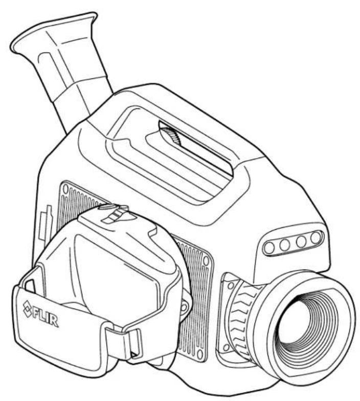
natural_image
Line drawing of a digital camera with no visible text or symbolsImportant note
Before operating the device, you must read, understand, and follow all instructions, warnings, cautions, and legal disclaimers.
Důležitá poznámka
User's manual FLIR GFx3xx series
Table of contents
1 Disclaimers ....1
1.1 Legal disclaimer ....1
1.2 U.S. Government Regulations....1
1.3 Copyright ......1
1.4 Quality assurance ....2
1.5 Patents....2
1.6 EULA Terms 2
1.7 EULA Terms ....3
2 Safety information ....4
2.1 Cautions and warnings related to a classified (hazardous) area......4
2.2 General cautions and warnings 6
2.2.1 Table of entity parameters .....9
2.2.2 Battery warning label 9
2.2.3 Laser warning label....9
2.2.4 Laser rules and regulations .....9
2.2.5 Compliance marking 9
2.2.6 Applicable markings 10
2.2.7 Certifications.... 10
2.2.8 Explosive (hazardous) environment 11
2.2.9 Safety.... 11
3 Notice to user 12
3.1 User-to-user forums 12
3.2 Calibration.... 12
3.3 Accuracy 12
3.4 Disposal of electronic waste 12
3.5 Training 12
3.6 Documentation updates 12
3.7 Note about authoritative versions.... 13
4 Customer help 14
4.1 General 14
4.2 Submitting a question 14
4.3 Downloads 15
5 Conditions of Use for Ex Equipment 16
6 Important note about training and applications.... 17
6.1 General 17
7 Important information about FLIR GFx3xx series service 18
8 List of accessories and services 19
9 Introduction....23
10 Example images....24
10.1 General 24
10.2 Images 24
11 Quick start guide....25
11.1 Starting the camera for the first time.... 25
11.2 Detecting a gas leak 30
11.2.1 Procedure 30
11.2.2 Related topics 31
11.3 Detecting a temperature....32
11.3.1 Procedure 32
11.3.2 Related topics 33
12 FLIR GFx3xx series general instrument check 34
13 A note about ergonomics 35
13.1 General 35
13.2 Figure 35
13.3 Related topics.... 36
14 Camera parts 37
14.1 View from the left 37
14.1.1 Figure.... 37
14.1.2 Explanation.... 37
14.2 View from the right 38
14.2.1 Figure.... 38
14.2.2 Explanation.... 38
14.3 View from the rear.... 39
14.3.1 Figure.... 39
14.3.2 Explanation.... 39
14.4 View from the rear with open cover 40
14.4.1 Figure.... 40
14.4.2 Explanation.... 40
14.5 Battery condition LED indicator.... 41
14.5.1 Figure.... 41
14.5.2 Explanation.... 41
14.6 Power LED indicator 41
14.6.1 Figure.... 41
14.6.2 Explanation.... 42
14.7 Laser pointer 42
14.7.1 General.... 42
14.7.2 Figure.... 42
14.7.3 Laser warning label 42
14.7.4 Laser rules and regulations 43
14.8 Serial number 43
14.8.1 General.... 43
14.8.2 Figure.... 43
15 Screen elements 44
15.1 Mode selector 44
15.1.1 Figure.... 44
15.1.2 Explanation.... 44
15.2 Result table and measurement tools 44
15.2.1 Figure.... 44
15.2.2 Explanation.... 44
15.3 Toolbox, indicators, and other objects.... 45
15.3.1 Figure.... 45
15.3.2 Explanation.... 45
ieving a good image 46
16.1 General 46
16.2 Adjusting the infrared camera focus 46
16.2.1 Figure.... 46
16.2.2 Procedure 46
16.3 Adjusting an image.... 47
16.3.1 General.... 47
16.3.2 Explanation of the adjustment methods.... 47
16.3.3 Procedure (Auto).... 47
16.3.4 Figure.... 47
16.3.5 Procedure (HSM) 47
16.3.6 Procedure (Manual) 47
16.4 Selecting a suitable temperature range.... 48
16.4.1 About temperature ranges.... 48
16.4.2 Understanding the temperature scale 48
16.4.3 Changing the temperature range 49
16.5 Selecting a suitable color palette 49
16.5.1 Procedure 49
16.6 Enabling or disabling histogram mode 49
16.6.1 General.... 49
16.6.2 Procedure 49
16.7 Enabling or disabling inverted color palette.... 50
16.7.1 Procedure 50
16.8 Changing object parameters 50
16.8.1 General.... 50
16.8.2 Types of parameters 50
16.8.3 Recommended values.... 50
16.8.4 Procedure 51
16.8.5 Related topics 51
17 Connecting external devices.... 52
17.1 General 52
17.2 Figure 52
17.3 Explanation 52
17.4 Formatting memory cards 53
18 Handling the camera.... 54
18.1 Charging the camera battery 54
18.1.1 Charging the battery using the power supply cable 54
18.1.2 Charging the battery using the stand-alone battery charger 54
18.2 Installing and removing the camera battery.... 55
18.2.1 Installing the battery.... 55
18.2.2 Removing the battery 56
18.3 Turning on the camera 56
18.3.1 Procedure 56
18.4 Turning off the camera 57
18.4.1 Procedure 57
18.5 Adjusting the viewing angle of the viewfinder.... 57
18.5.1 General.... 57
18.5.2 Figure.... 57
18.5.3 Procedure 57
18.6 Adjusting the viewfinder's dioptric correction 57
18.6.1 General.... 57
18.6.2 Figure.... 58
18.6.3 Procedure 58
18.7 Adjusting the camera grip 58
18.7.1 General.... 58
18.7.2 Figure.... 58
18.7.3 Procedure 58
18.8 Opening the display.... 59
18.8.1 Figure.... 59
18.9 Adjusting the viewing angle of the display.... 59
18.9.1 General.... 59
18.9.2 Figure.... 59
18.9.3 Procedure 60
18.10 Adjusting the infrared camera focus 60
18.10.1 Figure.... 60
18.10.2 Procedure 60
18.11 Using the zoom function 60
18.11.1 General.... 60
18.11.2 Procedure 60
18.12 Operating the laser pointer.... 61
18.12.1 Figure.... 61
18.12.2 Procedure 61
18.13 Laser warning label 62
18.14 Laser rules and regulations 62
18.15 Assigning functions to the programmable button.... 62
18.15.1 General.... 62
18.15.2 Procedure 62
19 Working with views and images.... 63
19.1 Saving infrared images.... 63
19.1.1 General.... 63
19.1.2 Image capacity 63
19.1.3 Saving an infrared image directly to an SD Memory Card....63
19.1.4 Previewing and saving an infrared image to an SD Memory Card 63
19.2 Opening an image.... 64
19.2.1 General.... 64
19.2.2 Procedure 64
19.3 Changing settings related to image presentation.... 64
19.3.1 General.... 64
19.3.2 Procedure 65
19.4 Editing a saved image.... 65
19.4.1 General.... 65
19.4.2 Procedure 65
19.5 Deleting a file.... 66
19.5.1 Procedure 66
20 Working with measurement tools 67
20.1 Laying out a measurement tool 67
20.1.1 General 67
20.1.2 Procedure 67
20.2 Moving or resizing a measurement tool.... 67
20.2.1 General.... 67
20.2.2 Procedure 67
20.3 Creating & setting up a difference calculation 67
20.3.1 General.... 67
20.3.2 Procedure 68
20.4 Changing object parameters 68
20.4.1 General.... 68
20.4.2 Types of parameters 68
20.4.3 Recommended values.... 69
20.4.4 Procedure 69
20.4.5 Related topics 69
21 Programming the camera 70
21.1 General 70
21.2 Procedure 70
22 Recording video clips 71
22.1 General 71
22.2 Procedure 71
23 Changing settings 72
23.1 General 72
23.2 Procedure 72
24 Technical data.... 73
24.1 Online field-of-view calculator 73
24.2 Note about technical data 73
24.3 Note about authoritative versions.... 73
24.4 FLIR GFx320 14.5° fixed lens 74
24.5 FLIR GFx320 24° fixed lens.... 79
25 Mechanical drawings 84
26 EU Declaration of conformity 87
27 MET Compliance Data Report (truncated).... 89
28 IEC/IECEE/Intertek Test Report (truncated).... 92
29 IEC/IECEE/Intertek CB Test Certificate 95
30 MET Laboratories Test Certificate (truncated).... 98
31 MET Laboratories Letter of Certification.... 100
32 Element Type Examination Certificate (truncated) 102
33 IECEx Technical Report: GB/EMT/ExTR16.0015/00 104
34 IECEx Quality Assessment Report: GB/EMT/QAR16.0003/00 106
35 Cleaning the camera 108
35.1 Camera housing, cables, and other items.... 108
35.1.1 Liquids.... 108
35.1.2 Equipment.... 108
35.1.3 Procedure 108
35.2 Infrared lens 108
35.2.1 Liquids.... 108
35.2.2 Equipment.... 108
35.2.3 Procedure 108
36 Cooler maintenance.... 110
36.1 General 110
36.2 Signs to watch for 110
37 Detectable gases.... 111
37.1 General 111
37.2 Gases that can be detected by FLIR GFx3xx 111
38 Why do some gases absorb infrared energy? 115
39 About FLIR Systems 118
39.1 More than just an infrared camera 119
39.2 Sharing our knowledge 120
39.3 Supporting our customers.... 120
40 Terms, laws, and definitions.... 121
41 Thermographic measurement techniques 123
41.1 Introduction 123
41.2 Emissivity.... 123
41.2.1 Finding the emissivity of a sample.... 123
41.3 Reflected apparent temperature.... 127
41.4 Distance 127
41.5 Relative humidity 127
41.6 Other parameters.... 127
42 About calibration.... 128
42.1 Introduction 128
42.2 Definition—what is calibration? 128
42.3 Camera calibration at FLIR Systems 128
42.4 The differences between a calibration performed by a user and that performed directly at FLIR Systems.... 129
42.5 Calibration, verification and adjustment.... 129
42.6 Non-uniformity correction.... 130
42.7 Thermal image adjustment (thermal tuning) 130
43 History of infrared technology.... 131
44 Theory of thermography.... 134
44.1 Introduction 134
44.2 The electromagnetic spectrum.... 134
44.3 Blackbody radiation.... 135
44.3.1 Planck's law 136
44.3.2 Wien's displacement law.... 137
44.3.3 Stefan-Boltzmann's law 138
44.3.4 Non-blackbody emitters.... 139
44.4 Infrared semi-transparent materials.... 141
45 The measurement formula.... 142
46 Emissivity tables 146
46.1 References.... 146
46.2 Tables 146
1
Disclaimers
1.1 Legal disclaimer
All products manufactured by FLIR Systems are warranted against defective materials and workmanship for a period of one (1) year from the delivery date of the original purchase, provided such products have been under normal storage, use and service, and in accordance with FLIR Systems instruction.
Uncooled handheld infrared cameras manufactured by FLIR Systems are warranted against defective materials and workmanship for a period of two (2) years from the delivery date of the original purchase, provided such products have been under normal storage, use and service, and in accordance with FLIR Systems instruction, and provided that the camera has been registered within 60 days of original purchase.
Detectors for uncooled handheld infrared cameras manufactured by FLIR Systems are warranted against defective materials and workmanship for a period of ten (10) years from the delivery date of the original purchase, provided such products have been under normal storage, use and service, and in accordance with FLIR Systems instruction, and provided that the camera has been registered within 60 days of original purchase.
Products which are not manufactured by FLIR Systems but included in systems delivered by FLIR Systems to the original purchaser, carry the warranty, if any, of the particular supplier only. FLIR Systems has no responsibility whatsoever for such products.
The warranty extends only to the original purchaser and is not transferable. It is not applicable to any product which has been subjected to misuse, neglect, accident or abnormal conditions of operation. Expendable parts are excluded from the warranty.
In the case of a defect in a product covered by this warranty the product must not be further used in order to prevent additional damage. The purchaser shall promptly report any defect to FLIR Systems or this warranty will not apply.
FLIR Systems will, at its option, repair or replace any such defective product free of charge if, upon inspection, it proves to be defective in material or workmanship and provided that it is returned to FLIR Systems within the said one-year period.
FLIR Systems has no other obligation or liability for defects than those set forth above.
No other warranty is expressed or implied. FLIR Systems specifically disclaims the implied warranties of merchantability and fitness for a particular purpose.
FLIR Systems shall not be liable for any direct, indirect, special, incidental or consequential loss or damage, whether based on contract, tort or any other legal theory.
This warranty shall be governed by Swedish law.
Any dispute, controversy or claim arising out of or in connection with this warranty, shall be finally settled by arbitration in accordance with the Rules of the Arbitration Institute of the Stockholm Chamber of Commerce. The place of arbitration shall be Stockholm. The language to be used in the arbitral proceedings shall be English.
1.2 U.S. Government Regulations
This product may be subject to U.S. Export Regulations. Please send any inquiries to exportquestions@flir.com.
1.3 Copyright
© 2016, FLIR Systems, Inc. All rights reserved worldwide. No parts of the software including source code may be reproduced, transmitted, transcribed or translated into any language or computer language in any form or by any means, electronic, magnetic, optical, manual or otherwise, without the prior written permission of FLIR Systems.
The documentation must not, in whole or part, be copied, photocopied, reproduced, translated or transmitted to any electronic medium or machine readable form without prior consent, in writing, from FLIR Systems.
Names and marks appearing on the products herein are either registered trademarks or trademarks of FLIR Systems and/or its subsidiaries. All other trademarks, trade names or company names referenced herein are used for identification only and are the property of their respective owners.
1.4 Quality assurance
The Quality Management System under which these products are developed and manufactured has been certified in accordance with the ISO 9001 standard.
FLIR Systems is committed to a policy of continuous development; therefore we reserve the right to make changes and improvements on any of the products without prior notice.
1.5 Patents
000439161; 000653423; 000726344; 000859020; 001707738; 001707746; 001707787; 001776519; 001954074; 002021543; 002021543-0002; 002058180; 002249953; 002531178; 002816785; 002816793; 011200326; 014347553; 057692; 061609; 07002405; 100414275; 101796816; 101796817; 101796818; 102334141; 1062100; 11063060001; 11517895; 1226865; 12300216; 12300224; 1285345; 1299699; 1325808; 1336775; 1391114; 1402918; 1404291; 1411581; 1415075; 1421497; 1458284; 1678485; 1732314; 17399650; 1880950; 1886650; 2007301511414; 2007303395047; 2008301285812; 2009301900619; 20100060357; 2010301761271; 2010301761303; 2010301761572; 2010305959313; 2011304423549; 2012304717443; 2012306207318; 2013302676195; 2015202354035; 2015304259171; 204465713; 204967995; 2106017; 2107799; 2115696; 2172004; 2315433; 2381417; 2794760001; 3006596; 3006597; 303330211; 4358936; 483782; 484155; 4889913; 4937897; 4995790001; 5177595; 540838; 579475; 584755; 599392; 60122153; 6020040116815; 602006006500.0; 6020080347796; 6020110003453; 615113; 615116; 664580; 664581; 665004; 665440; 67023029; 6707044; 677298; 68657; 69036179; 70022216; 70028915; 70028923; 70057990; 7034300; 710424; 7110035; 7154093; 7157705; 718801; 723605; 7237946; 7312822; 7332716; 7336823; 734803; 7544944; 7606484; 7634157; 7667198; 7809258; 7826736; 8018649; 8153971; 8212210; 8289372; 8340414; 8354639; 8384783; 8520970; 8565547; 8595689; 8599262; 8654239; 8680468; 8803093; 8823803; 8853631; 8933403; 9171361; 9191583; 9279728; 9280812; 9338352; 9423940; 9471970; 9595087; D549758.
1.6 EULA Terms
- You have acquired a device ("INFRARED CAMERA") that includes software licensed by FLIR Systems AB from Microsoft Licensing, GP or its affiliates ("MS"). Those installed software products of MS origin, as well as associated media, printed materials, and "online" or electronic documentation ("SOFTWARE") are protected by international intellectual property laws and treaties. The SOFTWARE is licensed, not sold. All rights reserved.
- IF YOU DO NOTAGREE TO THIS END USER LICENSE AGREEMENT ("EULA"), DO NOT USE THE DEVICE OR COPY THE SOFTWARE. INSTEAD, PROMPTLY CONTACT FLIR Systems AB FOR INSTRUCTIONS ON RETURN OF THE UNUSED DEVICE(S) FOR A REFUND. ANY USE OF THE SOFTWARE, INCLUDING BUT NOT LIMITED TO USE ON THE DEVICE, WILL CONSTITUTE YOUR AGREEMENT TO THIS EULA (OR RATIFICATION OF ANY PREVIOUS CONSENT).
- GRANT OF SOFTWARE LICENSE. This EULA grants you the following license:
- You may use the SOFTWARE only on the DEVICE.
NOT FAULT TOLERANT. THE SOFTWARE IS NOT FAULT TOLERANT. FLIR Systems AB HAS INDEPENDENTLY DETERMINED HOW TO USE THE SOFTWARE IN THE DEVICE, AND MS HAS RELIED UPON FLIR Systems AB TO CONDUCT SUFFICIENT TESTING TO DETERMINE THAT THE SOFTWARE IS SUITABLE FOR SUCH USE.
NO WARRANTIES FOR THE SOFTWARE. THE SOFTWARE is provided "AS IS" and with all faults. THE ENTIRE RISK AS TO SATISFACTORY QUALITY, PERFORMANCE, ACCURACY, AND EFFORT (INCLUDING LACK OF NEGLIGENCE) IS WITH YOU. ALSO, THERE IS NO WARRANTY AGAINST INTERFERENCE WITH YOUR ENJOYMENT OF THE SOFTWARE OR AGAINST INFRINGEMENT. IF YOU HAVE RECEIVED ANY WARRANTIES REGARDING THE DEVICE OR THE SOFTWARE, THOSE WARRANTIES DO NOT ORIGINATE FROM, AND ARE NOT BINDING ON, MS.
No Liability for Certain Damages. EXCEPT AS PROHIBITED BY LAW, MS SHALL HAVE NO LIABILITY FOR ANY INDIRECT, SPECIAL, CONSEQUENTIAL OR INCIDENTAL DAMAGES ARISING FROM OR IN CONNECTION WITH THE USE OR PERFORMANCE OF THE SOFTWARE. THIS LIMITATION SHALL APPLY EVEN IF ANY REMEDY FAILS OF ITS ESSENTIAL PURPOSE. IN NO EVENT SHALL MS BE LIABLE FOR ANY AMOUNT IN EXCESS OF U.S. TWO HUNDRED FIFTY DOLLARS (U.S.\$250.00).
Limitations on Reverse Engineering, Decompilation, and Disassembly. You may not reverse engineer, decompile, or disassemble the SOFTWARE, except and only to the extent that such activity is expressly permitted by applicable law notwithstanding this limitation.
- SOFTWARE TRANSFER ALLOWED BUT WITH RESTRICTIONS. You may permanently transfer rights under this EULA only as part of a permanent sale or transfer of the Device, and only if the recipient agrees to this EULA. If the SOFTWARE is an up grade, any transfer must also include all prior versions of the SOFTWARE.
- EXPORT RESTRICTIONS. You acknowledge that SOFTWARE is subject to U.S. export jurisdiction. You agree to comply with all applicable international and national laws that apply to the SOFTWARE, including the U.S. Export Administration Regulations, as well as end-user, end-use and destination restrictions issued by U.S. and other governments. For additional information see http://www.microsoft.com/exporting/.
1.7 EULA Terms
Qt4 Core and Qt4 GUI, Copyright ©2013 Nokia Corporation and FLIR Systems AB. This Qt library is a free software; you can redistribute it and/or modify it under the terms of the GNU Lesser General Public License as published by the Free Software Foundation; either version 2.1 of the License, or (at your option) any later version. This library is distributed in the hope that it will be useful, but WITHOUT ANY WARRANTY; without even the implied warranty of MERCHANTABILITY or FITNESS FOR A PARTICULAR PURPOSE. See the GNU Lesser General Public License, http://www.gnu.org/licenses/lgpl-2.1.html. The source code for the libraries Qt4 Core and Qt4 GUI may be requested from FLIR Systems AB.
2
Safety information
2.1 Cautions and warnings related to a classified (hazardous) area
| WARNING | ||
| Do not connect the camera to an external device while the camera is in a classified (hazardous) area. An explosion can occur. This can cause injury or death to persons and damage to the equipment. | ||
| WARNING | ||
| Do not replace the memory card while the camera is in a classified (hazardous) area. An explosion can occur. This can cause injury or death to persons and damage to the equipment. | ||
| WARNING | ||
| Do not open the cover for the connector and battery compartment while the camera is in a classified (hazardous) area. An explosion can occur. This can cause injury or death to persons and damage to the equipment. | ||
| WARNING | ||
| Do not replace the battery while the camera is in a classified (hazardous) area. An explosion can occur. This can cause injury or death to persons and damage to the equipment. | ||
| WARNING | ||
| Only connect ATEX/IECEx-approved intrinsically safe equipment to the USB mini-B and HDMI ports. If you do not obey this, an explosion can occur. This can cause injury or death to persons and damage to the equipment. | ||
| WARNING | ||
| Do not charge the battery in a classified (hazardous) area. An explosion can occur. This can cause injury or death to persons and damage to the equipment. | ||
| WARNING | ||
| Do not take the following items (that FLIR Systems supplies) into a classified (hazardous) area. An explosion can occur. This can cause injury or death to persons and damage to the equipment. | ||
| Product name Item part number | Sales part number | |
| Battery charger, incl. power supply with multi plugs | 1196210 T197692 | |
| Cigarette lighter adapter kit, 12 VDC, 1.2 m/3.9 ft. | 1910490 T198509 | |
| Hard transport case T199466 | T199466ACC | |
| HDMI to DVI cable 1.5 m T910816 | T910816ACC | |
| HDMI to HDMI cable 1.5 m T910815ACC | ||
| Screwdriver TX20 | T911309 | T911309ACC |
| Power supply, incl. multi plugs | T910814 T910814 | |
| USB cable Std A <-> Mini-B | 1910423 1910423 | |
| CAUTION | ||
| You must only use this charger when you charge the battery: Manufactured by Ten Pao industrial Co. Ltd.,IECEE CB reference certificate No. JPTUV-035588-M1 (supplied by TUV Rheinland Japan Ltd.), FLIR item part number 1196210 (FLIR sales part number T197692). FLIR Systems supplies the charger and the battery packs with the camera equipment. If you do not obey this, damage to the equipment can occur and the protection that the equipment gives can become unsatisfactory. | ||
| CAUTION | ||
| Only use the camera with a battery that has the item part number T199183 on it (that FLIR Systems supplies). If you do not obey this, damage to the equipment can occur and the protection that the equipment gives can become unsatisfactory. | ||
| CAUTION | ||
| Only use the camera with the following accessories (that FLIR Systems supplies). If you do not obey this,the protection that the equipment gives can become unsatisfactory. | ||
| Product name Item part number | ber Sales part number | |
| Hand strap T129728 T129728ACC | ||
| Neck strap T129729 | T129729ACC | |
| Lens cap T129739 T129739ACC | ||
| Lens cap strap T129867 | T129867ACC | |
| CAUTION | ||
| Do not connect a power supply to the battery while the battery is in the camera. Damage to the camera can occur. | ||
| CAUTION | ||
| Inside a classified (hazardous) area, only use the camera in a temperature range between -20°C to +40°C (-4°F to +104°F). This is the certification temperature range for explosive atmospheres.Outside a classified (hazardous) area, do not use the camera in temperatures more than +50°C (+122°F).High temperatures can cause damage to the camera. | ||
| CAUTION | ||
| Do not remove the infrared lens. If you do not obey this, the protection that the equipment gives can be-come unsatisfactory. | ||
| CAUTION | ||
| Do not make markings on the camera. Markings include labels, engravings, printing, melting, and so forth.If you do not obey this, the protection that the equipment gives can become unsatisfactory. | ||
| CAUTION | ||
| Make sure that you do not use a torque value that is more than 80 Ncm on the Torx T20 screw. Damage to the camera can occur if you do not obey this. | ||
Note The encapsulation rating is only applicable when all the openings on the camera are sealed with their correct covers, hatches, or caps. This includes the compartments for data storage, batteries, and connectors.
2.2 General cautions and warnings
| WARNING |
| Applicability: Class A digital devices.This equipment generates, uses, and can radiate radio frequency energy and if not installed and used in accordance with the instruction manual, may cause interference to radio communications. It has been tested and found to comply with the limits for a Class A computing device pursuant to Subpart J of Part 15 of FCC Rules, which are designed to provide reasonable protection against such interference when operated in a commercial environment. Operation of this equipment in a residential area is likely to cause interference in which case the user at his own expense will be required to take whatever measures may be required to correct the interference. |
| WARNING |
| Applicability: Cameras with one or more laser pointers.Do not look directly into the laser beam. The laser beam can cause eye irritation. |
| WARNING |
| Applicability: Cameras with one or more batteries.Do not disassemble or do a modification to the battery. The battery contains safety and protection devices which, if damage occurs, can cause the battery to become hot, or cause an explosion or an ignition. |
| WARNING |
| Applicability: Cameras with one or more batteries.If there is a leak from the battery and you get the fluid in your eyes, do not rub your eyes. Flush water and immediately get medical care. The battery fluid can cause injury to your eyes if you do this. |
| WARNING |
| Applicability: Cameras with one or more batteries.Do not continue to charge the battery if it does not become charged in the specified charging time. If you continue to charge the battery, it can become hot and cause an explosion or ignition. Injury to persons can occur. |
| WARNING |
| Applicability: Cameras with one or more batteries.Only use the correct equipment to remove the electrical power from the battery. If you do not use the correct equipment, you can decrease the performance or the life cycle of the battery. If you do not use the correct equipment, an incorrect flow of current to the battery can occur. This can cause the battery to become hot, or cause an explosion. Injury to persons can occur. |
| WARNING |
| Make sure that you read all applicable MSDS (Material Safety Data Sheets) and warning labels on containers before you use a liquid. The liquids can be dangerous. Injury to persons can occur. |
| CAUTION |
| Do not point the infrared camera (with or without the lens cover) at strong energy sources, for example, devices that cause laser radiation, or the sun. This can have an unwanted effect on the accuracy of the camera. It can also cause damage to the detector in the camera. |
| CAUTION |
| Applicability: Cameras with one or more batteries.Do not attach the batteries directly to a car's cigarette lighter socket, unless FLIR Systems supplies a specific adapter to connect the batteries to a cigarette lighter socket. Damage to the batteries can occur. |
| CAUTION |
| Applicability: Cameras with one or more batteries.Do not connect the positive terminal and the negative terminal of the battery to each other with a metal object (such as wire). Damage to the batteries can occur. |
| CAUTION |
| Applicability: Cameras with one or more batteries.Do not get water or salt water on the battery, or permit the battery to become wet. Damage to the batteries can occur. |
| CAUTION |
| Applicability: Cameras with one or more batteries.Do not make holes in the battery with objects. Damage to the battery can occur. |
| CAUTION |
| Applicability: Cameras with one or more batteries.Do not hit the battery with a hammer. Damage to the battery can occur. |
| CAUTION |
| Applicability: Cameras with one or more batteries.Do not put your foot on the battery, hit it or cause shocks to it. Damage to the battery can occur. |
| CAUTION |
| Applicability: Cameras with one or more batteries.Do not put the batteries in or near a fire, or into direct sunlight. When the battery becomes hot, the built-in safety equipment becomes energized and can stop the battery charging procedure. If the battery becomes hot, damage can occur to the safety equipment and this can cause more heat, damage or ignition of the battery. |
| CAUTION |
| Applicability: Cameras with one or more batteries.Do not put the battery on a fire or increase the temperature of the battery with heat. Damage to the battery and injury to persons can occur. |
| CAUTION |
| Applicability: Cameras with one or more batteries.Do not solder directly onto the battery. Damage to the battery can occur. |
 | CAUTION |
| Applicability: Cameras with one or more batteries.Do not use the battery if, when you use, charge, or put the battery in storage, there is an unusual smell from the battery, the battery feels hot, changes color, changes shape, or is in an unusual condition. Speak with your sales office if one or more of these problems occurs. Damage to the battery and injury to persons can occur. | |
 | CAUTION |
| Applicability: Cameras with one or more batteries.The temperature range through which you can charge the battery is 0°C to +45°C (+32°F to +113°F), except for the Korean market: +10°C to +45°C (+50°F to +113°F). If you charge the battery at temperatures out of this range, it can cause the battery to become hot or to break. It can also decrease the performance or the life cycle of the battery. | |
 | CAUTION |
| Applicability: Cameras with one or more batteries.The temperature range through which you can remove the electrical power from the battery is -15°C to +50°C (+5°F to +122°F), unless other information is specified in the user documentation or technical data. If you operate the battery out of this temperature range, it can decrease the performance or the life cycle of the battery. | |
 | CAUTION |
| Applicability: Cameras with one or more batteries.When the battery is worn, apply insulation to the terminals with adhesive tape or equivalent materials before you discard it. Damage to the battery and injury to persons can occur if you do not do this. | |
 | CAUTION |
| Applicability: Cameras with one or more batteries.Remove any water or moisture on the battery before you install it. Damage to the battery can occur if you do not do this. | |
 | CAUTION |
| Do not apply solvents or equivalent liquids to the camera, the cables, or other items. Damage to the battery and injury to persons can occur. | |
 | CAUTION |
| Be careful when you clean the infrared lens. The lens has an anti-reflective coating which is easily damaged. Damage to the infrared lens can occur. | |
 | CAUTION |
| Do not use too much force to clean the infrared lens. This can cause damage to the anti-reflective coating. | |
 | CAUTION |
| Applicability: Cameras with a viewfinder.Make sure that the beams from the intensive energy sources do not go into the viewfinder. The beams can cause damage to the camera. This includes the devices that emit laser radiation, or the sun. | |
Note The GPS module cannot retrieve GPS data when the camera is used inside buildings. Further, displaying GPS data is dependent on many factors, such as terrain, high buildings around the camera, and the number of detected satellites.
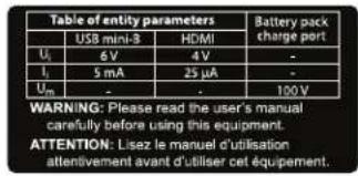
2.2.1 Table of entity parameters
The table shows the maximum input parameters for each port of the camera.
Table 2.1 Table of entity parameters
| Parameter (see note) | JSB mini-B HDMI Battery | y pack charge | port |
| U_i | 6 V 4 V | — | |
| I_i | 5 mA 25 μA | — | |
| U_m | — — | 100 V |
U_i = the maximum input voltage.
I_i = the maximum input current.
U_m = the maximum r.m.s. AC or DC voltage.
2.2.2 Battery warning label
The following warning label is affixed to the inside of the back cover:
2.2.3 Laser warning label
A laser warning label with the following information is affixed to the camera:
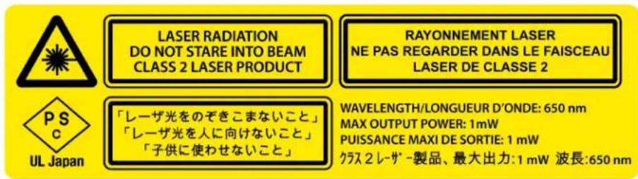
2.2.4 Laser rules and regulations
Wavelength: 635 nm. Maximum output power: 1 mW.
This product complies with 21 CFR 1040.10 and 1040.11 except for deviations pursuant to Laser Notice No. 50, dated June 24, 2007.
2.2.5 Compliance marking
2.2.5.1 Figure
A marking with the following information is laser-etched into the bottom of the camera housing:
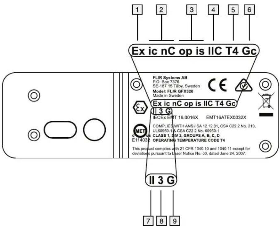
2.2.5.2 Explanation
- Ex = Explosion protection.
- Protection Type Codes: ic = intrinsic safe, nC = sealed device.
- Inherently safe optical device.
- Gas Group: IIC = acetylene, hydrogen, ethylene, and propane.
- Temperature Classification Code: T4 = <135 °C (<275 °F).
- Equipment Group: Group I = Mines, Group II = Other.
- Equipment Category: 3 = Equipment suitable for use in Zone 2.
-
G = Gas.
-
Equipment Protection Level (EPL): EPL is linked to the intended use and zones. Gc is linked to Gas Group II, Zone 2 and constitutes minimum protection level of either n, ic or pz.
2.2.6 Applicable markings
 | |
 | CE |
2.2.7 Certifications
- ATEX/IECEx, Ex ic nC op is IIC T4 Gc II 3 G
• ANSI/ISA-12.12.01-2013, Class I Division 2
• CSA 22.2 No. 213, Class I Division 2
2.2.8 Explosive (hazardous) environment
Standards related to explosive (hazardous) environment that the camera complies with:
• IEC 60079-0:2011
• IEC 60079-11:2011
• IEC 60079-15:2010 (partial)
• IEC 60079-28:2015
• BS EN 60079-0:2012
• BS EN 60079-11:2012
• BS EN 60079-15:2010
• BS EN 60079-28:2015
• ANSI/ISA-12.12.01-2013
• CSA 22.2 No. 213
• ATEX directive 2014/34/EU
2.2.9 Safety
Standards related to safety that the camera complies with:
• EN/UL/IEC 60950-1
3.1 User-to-user forums
Exchange ideas, problems, and infrared solutions with fellow thermographers around the world in our user-to-user forums. To go to the forums, visit:
http://forum.infraredtraining.com/
3.2 Calibration
Gas detection: no re-calibration recommendation. The ability to detect gases is not influenced by the calibration and will not degrade over time.
Temperature measurement: annual re-calibration recommended.
3.3 Accuracy
For very accurate results, we recommend that you wait 5 minutes after you have started the camera before measuring a temperature.
For cameras where the detector is cooled by a mechanical cooler, this time period excludes the time it takes to cool down the detector.
3.4 Disposal of electronic waste
As with most electronic products, this equipment must be disposed of in an environmentally friendly way, and in accordance with existing regulations for electronic waste.
Please contact your FLIR Systems representative for more details.
3.5 Training
To read about infrared training, visit:
- http://www.infraredtraining.com
- http://www.irtraining.com
- http://www.irtraining.eu
3.6 Documentation updates
Our manuals are updated several times per year, and we also issue product-critical notifications of changes on a regular basis.
To access the latest manuals, translations of manuals, and notifications, go to the Download tab at:
http://support.flir.com
It only takes a few minutes to register online. In the download area you will also find the last releases of manuals for our other products, as well as manuals for our historical and obsolete products.
3.7 Note about authoritative versions
The authoritative version of this publication is English. In the event of divergences due to translation errors, the English text has precedence.
Any late changes are first implemented in English.
4
Customer help
FLIR Customer Support Center
Home Answers Ask a Question Product Registration Downloads My Staff Service
FLIR Customer support
Get the most out of your FLIR products
Get Support foJ Your FLIR Products
Welcome to the FLIR Customer Support Center. This portal will help you as a FLIR customer to get the most out of your FLIR products. The portal gives you access to:
• The FLIR knowledgebase
- Ask our support team (requires registration)
• Software and documentation (requires registration)
• FLIR service contacts
Find Answers
We store all resolved problems in our solution database. Search by product, category, keywords, or phrases.
Search by Keyword
Search All Answers
See All Popular Answers
To find a datasheet for a current product, click on a picture.
To find a datasheet for a legacy product, click here.
FLIR Ex

FLIR EXX

FLIR Kxx

FLIR T4Box

FLIR T60x

EUR G300

henmaCAM ^TM
Gas FindIR

FLIR GF3xx

FLIR AD

FLIR Ax5

FLIR A3xx

More...
Product catalog
Please right-click the links below and select Save Target As... to save the file.
US Letter (28 Mb)
34(27.4 MB)
Important legal disclaimer, dangers, warnings, and cautions
Accessories
4.1 General
For customer help, visit:
http://support.flir.com
4.2 Submitting a question
To submit a question to the customer help team, you must be a registered user. It only takes a few minutes to register online. If you only want to search the knowledgebase for existing questions and answers, you do not need to be a registered user.
When you want to submit a question, make sure that you have the following information to hand:
- The camera model
• The camera serial number
- The communication protocol, or method, between the camera and your device (for example, SD card reader, HDMI, Ethernet, USB, or FireWire)
• Device type (PC/Mac/iPhone/iPad/Android device, etc.)
- Version of any programs from FLIR Systems
• Full name, publication number, and revision number of the manual
4.3 Downloads
On the customer help site you can also download the following, when applicable for the product:
- Firmware updates for your infrared camera.
- Program updates for your PC/Mac software.
- Freeware and evaluation versions of PC/Mac software.
- User documentation for current, obsolete, and historical products.
- Mechanical drawings (in *.dxf and *.pdf format).
- Cad data models (in *.stp format).
- Application stories.
• Technical datasheets. - Product catalogs.
Conditions of Use for Ex Equipment
| WARNING |
| Do not connect the camera to an external device while the camera is in a classified (hazardous) area. An explosion can occur. This can cause injury or death to persons and damage to the equipment. |
| WARNING |
| Do not replace the memory card while the camera is in a classified (hazardous) area. An explosion can occur. This can cause injury or death to persons and damage to the equipment. |
| WARNING |
| Do not open the cover for the connector and battery compartment while the camera is in a classified (hazardous) area. An explosion can occur. This can cause injury or death to persons and damage to the equipment. |
| WARNING |
| Do not replace the battery while the camera is in a classified (hazardous) area. An explosion can occur. This can cause injury or death to persons and damage to the equipment. |
| WARNING |
| Only connect ATEX/IECEx-approved intrinsically safe equipment to the USB mini-B and HDMI ports. If you do not obey this, an explosion can occur. This can cause injury or death to persons and damage to the equipment. |
| CAUTION |
| You must only use this charger when you charge the battery: Manufactured by Ten Pao industrial Co. Ltd., IECEE CB reference certificate No. JPTUV-035588-M1 (supplied by TUV Rheinland Japan Ltd.), FLIR item part number 1196210 (FLIR sales part number T197692). FLIR Systems supplies the charger and the battery packs with the camera equipment. If you do not obey this, damage to the equipment can occur and the protection that the equipment gives can become unsatisfactory. |
| CAUTION |
| Only use the camera with a battery that has the item part number T199183 on it (that FLIR Systems supplies). If you do not obey this, damage to the equipment can occur and the protection that the equipment gives can become unsatisfactory. |
Note The encapsulation rating is only applicable when all the openings on the camera are sealed with their correct covers, hatches, or caps. This includes the compartments for data storage, batteries, and connectors.
6
Important note about training and applications
6.1 General
Infrared inspection of gas leaks, furnaces, and high-temperature applications—including infrared image and other data acquisition, analysis, diagnosis, prognosis, and reporting—is a highly advanced skill. It requires professional knowledge of thermography and its applications, and is, in some countries, subject to certification and legislation.
Consequently, we strongly recommend that you seek the necessary training before carrying out inspections. Please visit the following site for more information:
http://www.infraredtraining.com
7
Important information about FLIR GFx3xx series service
- Service must only be performed by an authorized FLIR service department.
- Contact the service department before shipping the camera. Many problems can be resolved on the phone—if so, the camera does not need to be shipped.
- If the camera has been subject to shock or vibration, it should be sent to an authorized FLIR service department for control.
List of accessories and services
| Product name Item part number Sales part number | |||
| Battery T199183 T199183ACC |  WARNING WARNING | ||
| Do not replace this item inside a classified (hazardous) area. An explosion can occur. An explosion can cause death or injury to persons and damage to the equipment. | |||
| Battery charger, incl. power supply with multi plugs | 1196210 T197692 | [1743] WARNING | |
| Do not take this item into a classified (hazardous) area. An explosion can occur. An explosion can cause death or injury to persons and damage to the equipment. | |||
| Cigarette lighter adapter kit, 12 VDC, 1.2 m/3.9 ft. | 1910490 T198509 | [4374] WARNING | |
| Do not take this item into a classified (hazardous) area. An explosion can occur. An explosion can cause death or injury to persons and damage to the equipment. | |||
| FLIR IR Camera Player | N/A DSW-10000 | ||
| FLIR Reporter Professional (license only) | N/A T198586 | ||
| FLIR ResearchIR Max + HSDR 4 (hardware sec. dev.) | N/A T198697 | ||
| FLIR ResearchIR Max + HSDR 4 (printed license key) | N/A | T199014 | |
| FLIR ResearchIR Max + HSDR 4 Upgrade (printed license key) | N/A | T199044 | |
| FLIR ResearchIR Max 4 (hardware sec. dev.) | N/A T198696 | ||
| FLIR ResearchIR Max 4 (printed license key) | N/A | T199013 | |
| FLIR ResearchIR Max 4 Upgrade (printed license key) | N/A T199043 | ||
| FLIR ResearchIR Standard 4 (hardware sec. dev.) | N/A T198731 | ||
| FLIR ResearchIR Standard 4 (printed license key) | N/A | T199012 | |
| FLIR ResearchIR Standard 4 Upgrade (printed license key) | N/A T199042 | ||
| FLIR Tools N/A T198584 | |||
| FLIR Tools+ (download card incl. license key) | N/A T198583 | ||
| FLIR VideoReport | N/A | T198585 | |
| Hand strap T129728 T129728ACC | |||
| Hard transport case T199466 | T199466ACC | WARNINGDo not take this item into a classified (hazardous) area.An explosion can occur.An explosion can cause death or injury to persons and damage to the equipment. | |
| HDMI to DVI cable 1.5 m | T910816 | T910816ACC | WARNINGDo not take this item into a classified (hazardous) area.An explosion can occur.An explosion can cause death or injury to persons and damage to the equipment. |
| HDMI to HDMI cable 1.5 m | T910815 | T910815ACC | WARNINGDo not take this item into a classified (hazardous) area.An explosion can occur.An explosion can cause death or injury to persons and damage to the equipment. |
| Lens cap T129739 | T129739ACC | ||
| Lens cap strap T129867 | T129867ACC | ||
| Memory card SDHC 4 GB | T911650 | T911650ACC | |
| WARNING | |||
| Do not replace this item inside a classified (hazardous) area. An explosion can occur. An explosion can cause death or injury to persons and damage to the equipment. | |||
| Neck strap T129729 | T129729ACC | ||
| Power supply, incl. multi plugs | T910814 T910814 | ||
| WARNING | |||
| Do not take this item into a classified (hazardous) area. An explosion can occur. An explosion can cause death or injury to persons and damage to the equipment. | |||
| Screwdriver TX20 T911309 | T911309ACC | ||
| WARNING | |||
| Do not take this item into a classified (hazardous) area. An explosion can occur. An explosion can cause death or injury to persons and damage to the equipment. | |||
| ThermoVisionTM Lab-VIEW® Digital Toolkit Ver. 3.3 | N/A T198566 | ||
| ThermoVisionTM System Developers Kit Ver. 2.6 | N/A T198567 | ||
| USB cable Std A <-> Mini-B | 1910423 1910423 | ||
| [KEZH] WARNINGDo not take this item into a classified (hazardous) area. An explosion can occur. An explosion can cause death or injury to persons and damage to the equipment. | |||
Note FLIR Systems reserves the right to discontinue models, parts or accessories, and other items, or to change specifications at any time without prior notice.
Introduction
natural_image
Black FLIR camera with visible lens and control panel (no text or symbols on body)Thank you for choosing a FLIR GFx3xx series camera from FLIR Systems.
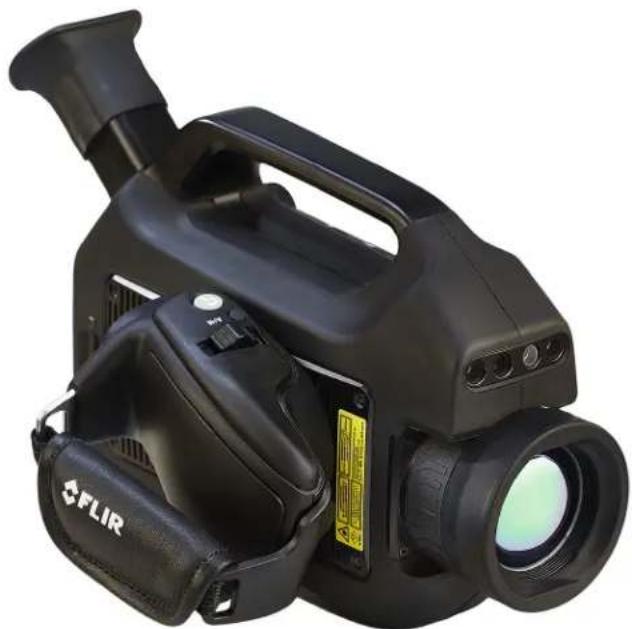
The FLIR GFx3xx series camera is an infrared camera for optical gas imaging (OGI) in explosive atmospheres that visualizes and pinpoints leaks of methane and other volatile organic compounds (VOCs), without the need to shut down the operation. The portable camera also greatly improves operator safety, by detecting emissions at a safe distance, and helps to protect the environment by tracing leaks of environmentally harmful gases.
The FLIR GFx3xx series camera is used in industrial settings such as oil refineries, natural gas processing plants, offshore platforms, chemical/petrochemical industries, and biogas and power generation plants.
Main features:
• Certified for use in an explosive atmosphere.
- Improved efficiency: The FLIR GFx320 reduces revenue loss by pinpointing gas leaks quickly and efficiently, and from a distance. It also reduces the inspection time by allowing a broad area to be scanned rapidly and without the need to interrupt the industrial process. The FLIR GFx320 is also used for temperature measurement, which makes it even more useful for predictive maintenance.
- Increased worker safety: OGI allows gas leaks to be detected in a non-contact mode and from a safe distance. This reduces the risk of the user being exposed to invisible and potentially harmful or explosive chemicals. With a FLIR GFx320 gas imaging camera it is easy to scan areas of interest that are difficult to reach with conventional methods. The camera is ergonomically designed, with a bright LCD and tiltable viewfinder, which facilitates its use over a full working day.
- Protecting the environment: Several VOCs are dangerous to human health or cause harm to the environment, and are usually governed by regulations. Even small leaks can be detected and documented using the FLIR GFx320 camera.
Example images
10.1 General
This section contains example images from various applications.
Note Gas leaks are easier to see in live image mode, which is the reason the leaks are indicated with a red dot in the images below.
10.2 Images
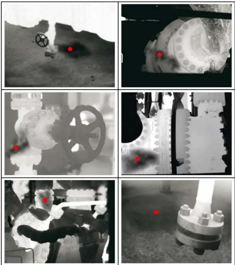
Quick start guide
11.1 Starting the camera for the first time
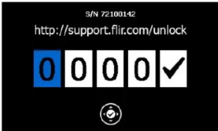
The first time you start the camera, you need to unlock the camera by entering a camera unique code. The code is based on the serial number of the camera. To get the camera unique code, you must log in with a FLIR Customer Support account and register the camera. If you already have an existing FLIR Customer Support account, you can use the same login credentials.
Follow this procedure:
-
Before operating the camera, you must read, understand, and follow the warnings, cautions, and notes in sections, page and 5 Conditions of Use for Ex Equipment, page 16.
-
Charge the battery for four hours, or until the green battery condition LED glows continuously.
Note Do this at room temperature.
-
Put the battery into the battery compartment.
-
Insert a memory card into the card slot.
-
Close the cover and tighten the Torx T20 screw to 80 N cm.
-
Push the Ⓐ button to turn on the camera. This displays the following dialog box:

Note When the camera is turned on, a mechanical cooler will begin cooling down the infrared detector. The mechanical cooler has a sound that resembles a subdued motor. This sound is normal. When the cooling procedure is completed, there is a distinct change of the sound.
- Use a computer or other device with internet access and go to the following website:
http://support.flir.com/unlock
This displays the following dialog:
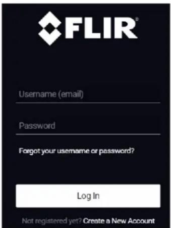
- To log in with your existing FLIR Customer Support account, do the following:
8.1. Enter your Username and Password.
8.2. Click Log In.
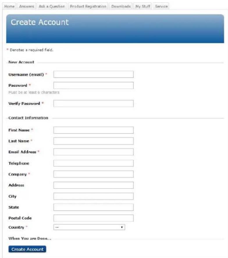
- To create a new FLIR Customer Support account, do the following:
9.1. Click Create a New Account.
9.2. Enter the required information and click Create Account.
FLIR Customer Support Center
- On the camera, push the joystick. This displays a dialog box. The serial number (S/N) of the camera is displayed at the top of the screen.
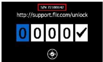
Note The serial number is also available on a label in the battery compartment, see section 14.8 Serial number, page 43.
- On the computer, enter the serial number of the camera and click Validate.
FLIR Customer Support Center
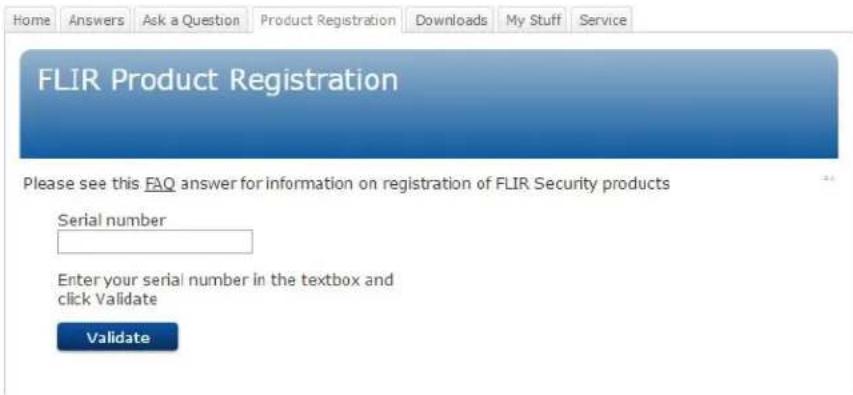
- When the serial number is validated, click Continue.
FLIR Customer Support Center
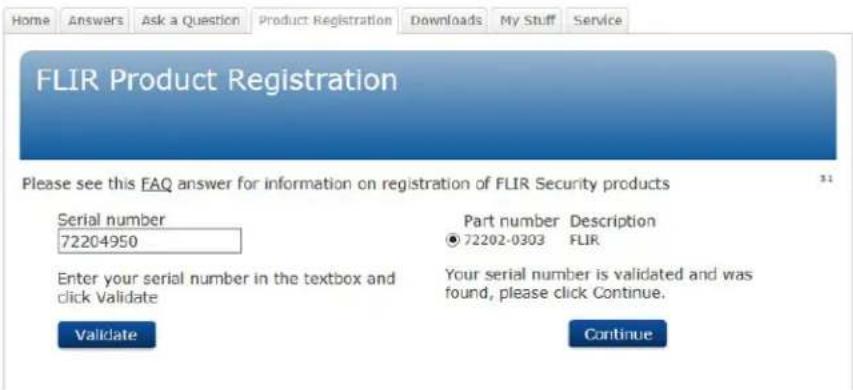
- Enter the required information and click Register Product.
FLIR Customer Support Center
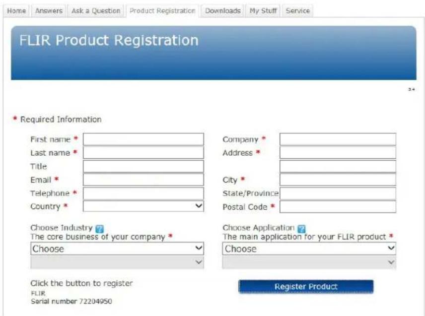
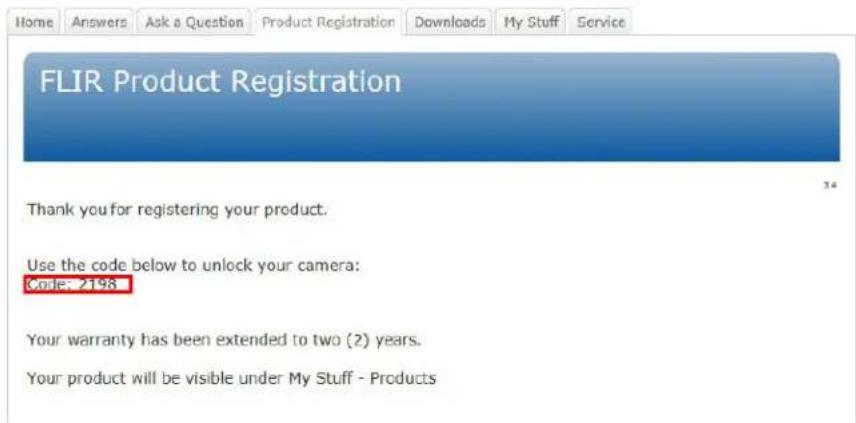
- When the registration is completed, the four-digit code is displayed.
FLIR Customer Support Center
Note
- The code is also sent by e-mail to the address registered with your FLIR Customer Support account.
-
The code is also displayed in your FLIR Customer Support portal under My Stuff > Products.
-
On the camera, do the following to enter the code:
-
Move the joystick up/down to select a digit.
- Move the joystick left/right to navigate to the previous/next digit.
- When all digits have been entered, move the joystick right to selecPush the joystick to confirm.
-
Depending on the entered code, one of the following will happen:
-
If the entered code is correct, is momentarily displayed. Then the unlock dialog box closes.
-
If the entered code is incorrect, is momentarily displayed. Then the unlock dialog is zeroed and you can enter the code again.
-
The camera is now fully operational and, depending on the status of the cool-down procedure, a progress bar or a video image is displayed.
- To turn off the camera, push and hold a button until the progress bar that is displayed on the screen reaches the end.
Note The next time you turn on the camera, it will be fully operational from its start-up. You do not have to go through the unlock procedure again.
11.2 Detecting a gas leak
11.2.1 Procedure
Follow this procedure:
-
Before operating the camera, you must read, understand, and follow the warnings, cautions, and notes in sections, page and 5 Conditions of Use for Ex Equipment, page 16.
-
Charge the battery until the green battery condition LED glows continuously.
Note Do this at room temperature.
- Put the battery into the battery compartment.
- Insert a memory card into the card slot.
-
Close the cover and tighten the Torx T20 screw to 80 N cm.
-
Push the Ⓐ button to turn on the camera. A mechanical cooler will begin cooling down the infrared detector. A test image and a progress bar are displayed during cooldown. When the cooling procedure is completed, a video image will be displayed.
Note
- The mechanical cooler has a sound that resembles a subdued motor. This sound is normal. When the cooling procedure is completed, there is a distinct change in the sound.
-
The cooling procedure typically takes 7 minutes. At high ambient temperatures the cooling time may increase 30% or more.
-
Wait until the cooling procedure is completed. Then turn the mode wheel to enter video mode.
- Push the temperature range button, then do the following:
8.1. Move the joystick up/down to choose a suitable temperature range for your object.
8.2. Push the temperature range button to confirm and leave the setup mode.
-
Aim the camera toward the target of interest.
-
Adjust the infrared camera focus by doing the following:
-
For far focus, rotate the focus ring counter-clockwise (looking at the front of the lens).
-
For near focus, rotate the focus ring clockwise (looking at the front of the lens).
-
If there is a gas leak, and the gas is one of the gases that the camera can detect, yo will now see the leak on the screen. The leak will resemble a smoke plume emanating from the point of the leak.
-
To start recording a video clip, push the button.
- To stop recording a video clip, push a button again. This will display a preview dialog box.
- To save the video clip, move the joystick to select and push the joystick.
- To move the video clip to a computer, do one of the following:
- Remove the memory card and insert it in a card reader connected to a computer.
- Connect a computer to the camera using a USB Mini-B cable.
Note To enable file transfer via the USB port, the USB mode setting must be set
to Mass Storage Device. The setting is made in setup mode in the Camera tab. Select USB mode > Mass Storage Device.
- Move the video clip from the card or camera using a drag-and-drop operation.
- To turn off the camera, push and hold rebutton until the progress bar that is displayed on the screen reaches the end.
11.2.2 Related topics
• 18.1.1 Charging the battery using the power supply cable, page 54
• 18.1.2 Charging the battery using the stand-alone battery charger, page 54
• 18.2.1 Installing the battery, page 55
• 17 Connecting external devices, page 52
• 20.1 Laying out a measurement tool, page 67
• 19.1 Saving infrared images, page 63
• 22 Recording video clips, page 71
• 37 Detectable gases, page 111
11.3 Detecting a temperature
11.3.1 Procedure
Follow this procedure:
-
Before operating the camera, you must read, understand, and follow the warnings, cautions, and notes in sections, page and 5 Conditions of Use for Ex Equipment, page 16.
-
Charge the battery until the green battery condition LED glows continuously.
Note Do this at room temperature.
-
Put the battery into the battery compartment.
-
Insert a memory card into the card slot.
-
Close the cover and tighten the Torx T20 screw to 80 N cm.
-
Push the Ⓐ button to turn on the camera. A mechanical cooler will begin cooling down the infrared detector. A test image and a progress bar are displayed during cooldown. When the cooling procedure is completed, a video image will be displayed.
Note
- The mechanical cooler has a sound that resembles a subdued motor. This sound is normal. When the cooling procedure is completed, there is a distinct change in the sound.
-
The cooling procedure typically takes 7 minutes. At high ambient temperatures the cooling time may increase 30% or more.
-
Wait until the cooling procedure is completed. Then turn the mode wheel to enter camera mode.
- Push the temperature range button, then do the following:
8.1. Move the joystick up/down to choose a suitable temperature range for your object.
8.2. Push the temperature range button to confirm and leave the setup mode.
-
Aim the camera toward the target of interest.
-
Adjust the infrared camera focus by doing the following:
-
For far focus, rotate the focus ring counter-clockwise (looking at the front of the lens).
-
For near focus, rotate the focus ring clockwise (looking at the front of the lens).
-
Add a spotmeter by doing the following:
11.1. Push the button to display a menu.
11.2. Move the joystick left/right to the Edit tab.
11.3. Move the joystick up/down to Add spot.
11.4. Push the joystick. A spotmeter is now displayed in the middle of the screen. The spotmeter temperature is displayed in the result table in the top left corner of the screen.
11.5. Move the joystick up/down/left/right to move the spotmeter on the screen.
11.6. Push the button to leave the setup mode.
-
To save an image directly, push and hold a button for more than one second.
-
To move the image to a computer, do one of the following:
- Remove the memory card and insert it in a card reader connected to a computer.
- Connect a computer to the camera using a USB Mini-B cable.
Note To enable file transfer via the USB port, the USB mode setting must be set to Mass Storage Device. The setting is made in setup mode in the Camera tab. Select USB mode > Mass Storage Device.
- Move the image from the card or camera using a drag-and-drop operation.
- To turn off the camera, push and hold a button until the progress bar that is displayed on the screen reaches the end.
11.3.2 Related topics
• 18.1.1 Charging the battery using the power supply cable, page 54
• 18.1.2 Charging the battery using the stand-alone battery charger, page 54
• 18.2.1 Installing the battery, page 55
• 17 Connecting external devices, page 52
• 20.1 Laying out a measurement tool, page 67
• 19.1 Saving infrared images, page 63
12
FLIR GFx3xx series general instrument check
The following general instrument check process ensures that the camera can detect the intended gas compounds with the same sensitivity as when originally manufactured.
- Make sure that the camera powers on.
- Make sure that the camera completes the cool-down process and produces a live infrared image.
- Make sure that the camera does not report any error messages on startup.
- Make sure that the camera focuses properly.
- Make sure that the camera is able to engage HSM mode.
A note about ergonomics
13.1 General
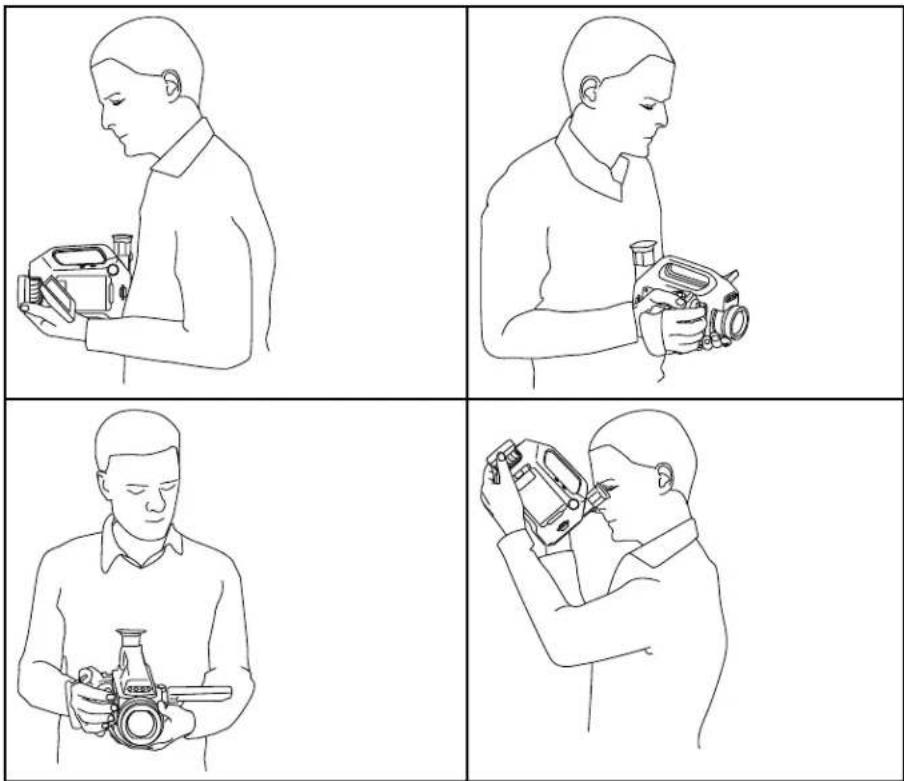
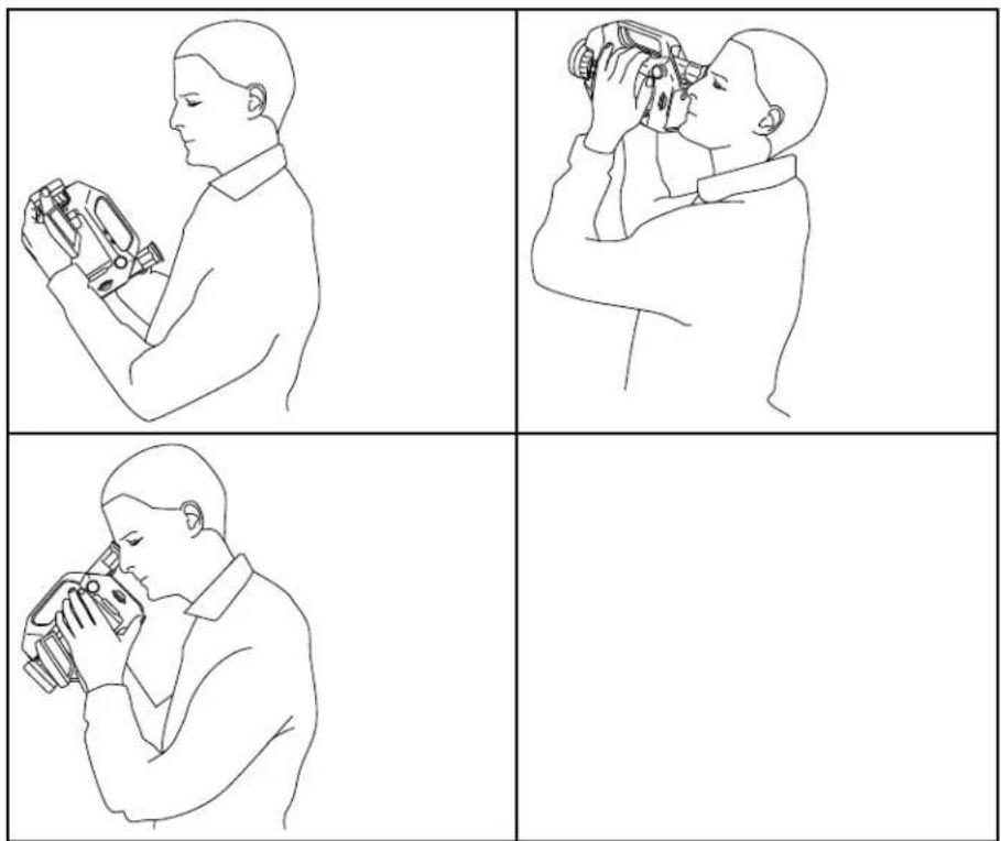
To prevent overstrain injuries, it is important that you hold the camera ergonomically correct. This section gives advice and examples on how to hold the camera.
Note Please note the following:
• Always tilt the viewfinder to fit your work position.
• Always adjust the viewing angle of the display to fit your work position.
• Always adjust the camera grip to fit your work position.
- When you hold the camera, make sure that you support the camera housing with your left hand too. This decreases the strain on your right hand.
13.2 Figure
13.3 Related topics
• 18.5 Adjusting the viewing angle of the viewfinder, page 57
• 18.7 Adjusting the camera grip, page 58
• 18.9 Adjusting the viewing angle of the display, page 59
Camera parts
14.1 View from the left
14.1.1 Figure
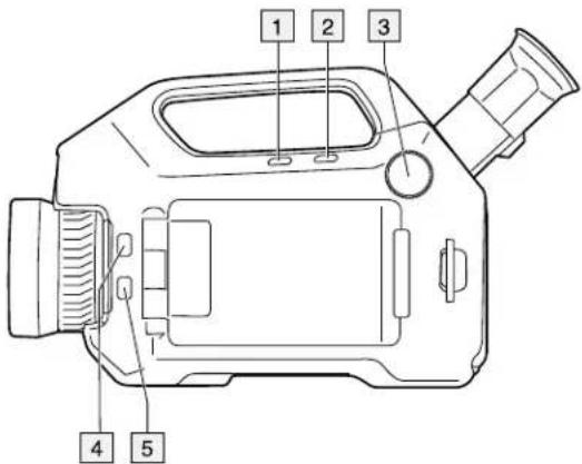
14.1.2 Explanation
-
Programmable button for one of the following functions:
-
Change the zoom factor.
- Hide/show graphics.
- Change the polarity.
- Change the palette.
You program the button in setup mode in the Preferences tab.
-
Temperature range button.
-
Mode wheel with the following modes:
-
Camera mode: Save images.
• Video mode: Record video clips and video sequences. - Archive mode: View saved images, video clips, and video sequences.
- Program mode: Set up periodical saving of images.
-
Setup mode: Change the general settings.
-
Laser button.
- Button to go between infrared mode and digital camera mode.
14.2 View from the right
14.2.1 Figure
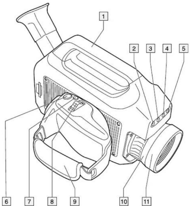
14.2.2 Explanation
- Camera handle.
- Digital camera lamp. When you are in digital camera mode, you turn on the lamps by pushing the joystick.
- Digital video camera.
- Laser pointer.
- Digital camera lamp. When you are in digital camera mode, you turn on the lamps by pushing the joystick.
6. S button (Preview/Save).
Function in camera mode:
- To preview an image before saving it, push and release the button.
• To save an image directly, push and hold the button for more than 1 second.
Function in video mode:
• To start recording a video clip, push the button.
- To stop recording a video clip, push the button again.
- Push and release the button to change the image adjustment method between Auto, Manual, and HSM.
- Push and hold down the button for more than 1 second to perform a non-uniformity correction (NUC).
Note
- Performing an NUC is typically not needed during normal operating procedures.
The NUC should be performed against a uniform temperature scene. Otherwise, the present image will create an artifact that will appear as a superimposed ghost image. If this occurs, restart the camera. - When an NUC has been performed, an asterisk (*) is displayed in the result table, indicating that the measurement may be affected. The asterisk disappears when the camera is restarted.
-
For more information, see section 42 About calibration, page 128.
-
ZOOM button.
Function:
- When an image is in preview or archive mode, push the button left/right to adjust the zoom.
-
When an image is in live mode, the button has no function.
-
Hand strap.
- Focus ring on the infrared lens.
- Infrared lens.
14.3 View from the rear
14.3.1 Figure
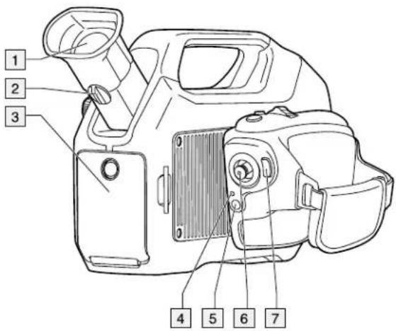
14.3.2 Explanation
- Viewfinder.
- Adjustment knob for the viewfinder's diopter correction.
-
Cover for the connector and battery compartment. The cover is fastened with a Torx screw (T20).
-
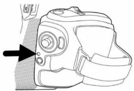
Power LED indicator.
-
Ⓞ button (On/off).
Function:
- To turn on the camera, push and release the button. - To turn off the camera, push and hold the button until the progress bar that is displayed on the screen reaches the end.
- Joystick.
Function:
- To navigate in menus and dialog boxes, move the joystick up/down/left/right. - To change values, move the joystick up/down/left/right. - To select or confirm choices, push the joystick.
- button (Menu/Back).
14.4 View from the rear with open cover
14.4.1 Figure
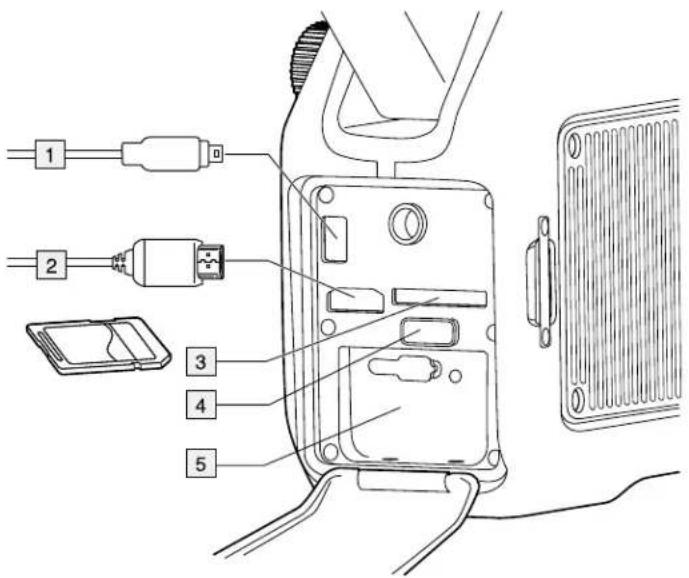
14.4.2 Explanation
- USB Mini-B cable (to connect the camera to a computer).
- HDMI cable (for live video output).
- Memory card slot.
- Battery release button.
- Battery.

WARNING
Do not open the cover for the connector and battery compartment while the camera is in a classified (hazardous) area. An explosion can occur. This can cause injury or death to persons and damage to the equipment.
| CAUTION |
| Make sure that you do not use a torque value that is more than 80 Ncm on the Torx T20 screw.to the camera can occur if you do not obey this. |
| CAUTION |
| Only use the camera with a battery that has the item part number T199183 on it (that FLIR Syste plies). If you do not obey this, damage to the equipment can occur and the protection that the eq gives can become unsatisfactory. |
14.5 Battery condition LED indicator
14.5.1 Figure
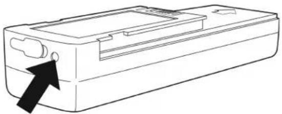
natural_image
Line drawing of a rectangular electronic device with a black arrow pointing to its side panel (no text or symbols)14.5.2 Explanation
This table gives an explanation of the battery condition LED indicator:
| Type of signal Explanation | |
| The LED is red and glows continuously. The battery needs to be charged.. | |
| The LED is green and flashes. The battery is being charged. | |
| The LED is green and glows continuously. The battery is fully charged. | |
| The LED is off. The power supply or the stand-alone batterycharger is disconnected from the battery. | |
14.6 Power LED indicator
14.6.1 Figure
natural_image
Line drawing of a camera module with no text or symbols14.6.2 Explanation
This table gives an explanation of the power LED indicator:
| Type of signal Explanation | |
| The LED is off. The camera is off. | |
| The LED is green. The camera is on. |
14.7 Laser pointer
14.7.1 General
The camera has a laser pointer. When the laser pointer is on, you will see a laser dot approximately at the target.
14.7.2 Figure
This figure shows the difference in position between the laser pointer and the optical center of the infrared lens. The laser pointer and the optical axis are parallel.
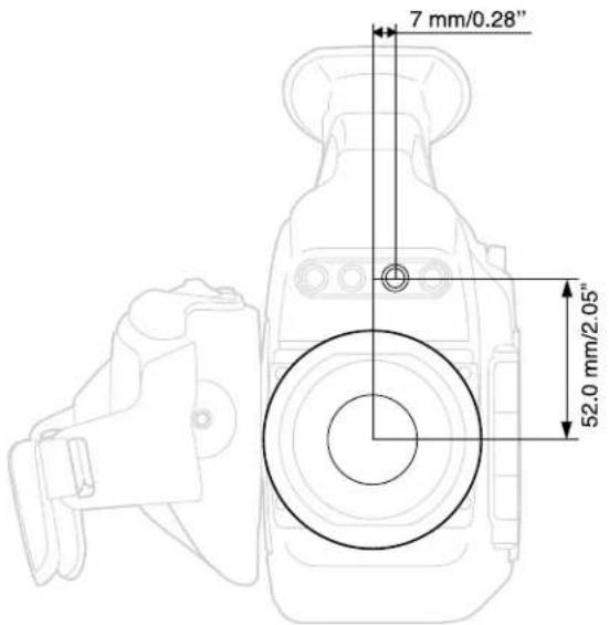
| WARNING |
| Do not look directly into the laser beam. The laser beam can cause eye irritation. |
Note The symbol is displayed on the screen when the laser pointer is on.
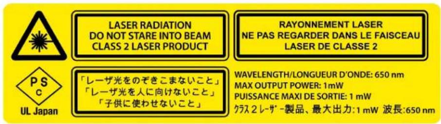
14.7.3 Laser warning label
A laser warning label with the following information is affixed to the camera:
14.7.4 Laser rules and regulations
Wavelength: 635 nm. Maximum output power: 1 mW.
This product complies with 21 CFR 1040.10 and 1040.11 except for deviations pursuant to Laser Notice No. 50, dated June 24, 2007.
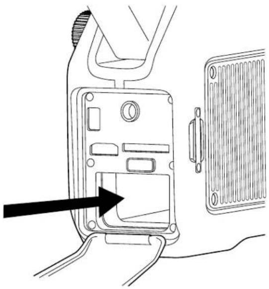
14.8 Serial number
14.8.1 General
The serial number of the camera is provided on a label in the battery compartment.
14.8.2 Figure
natural_image
Line drawing of a device panel with an arrow pointing to a component, next to a grid-like structure (no text or symbols)Screen elements
15.1 Mode selector
Note To select the mode, turn the mode when on the left side of the camera.
15.1.1 Figure
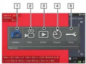
15.1.2 Explanation
- Camera mode.
- Video mode: Record video clips (*.mp4) and video sequences (*.seq).
- Archive mode: View saved images and video sequences.
- Program mode: Set up periodical saving of images.
- Setup mode: Change the general settings.
15.2 Result table and measurement tools
15.2.1 Figure
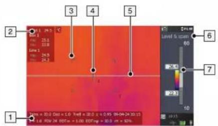
15.2.2 Explanation
- Status bar.
- Result table.
- Area (measurement tool).
- Spotmeter (measurement tool).
- Line (measurement tool).
- Adjustment method indicator.
- Temperature scale.
15.3 Toolbox, indicators, and other objects
Note To display the menu, push the button.
15.3.1 Figure
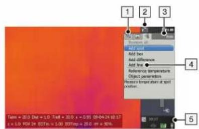
15.3.2 Explanation
- Menu tab.
- Mode indicator.
- Menu tab name.
- Menu item.
- Status indicators:
• Time.
- Date.
- GPS indicator.
- USB indicator.
- Power indicator.
- Memory card indicator. The indicator shows the amount of free space on the memory card. As a warning, the indicator will turn yellow and then red as the amount of free space decreases.
Achieving a good image
16.1 General
A good image depends on several different settings, although some settings affect the image more than other.
These are the settings you need to experiment with:
- Adjusting the infrared camera focus.
- Adjusting the image, using Auto, Manual, or HSM (= High Sensitivity Mode).
- Selecting a suitable temperature range.
- Selecting a suitable color palette.
- Enabling or disabling histogram mode.
- Enabling or disabling inverted color palette.
- Changing object parameters.
This section explains how to change these settings.
16.2 Adjusting the infrared camera focus
Note Do not touch the lens surface when you adjust the infrared camera focus. If this happens, clean the lens according to the instructions in 35.2 Infrared lens, page 108.
16.2.1 Figure
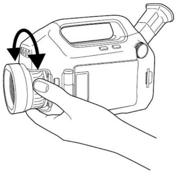
natural_image
Line drawing of a hand holding a digital camera with an arrow indicating rotation (no text or symbols)16.2.2 Procedure
Do one of the following:
- For far focus, rotate the focus ring counter-clockwise (looking at the front of the lens)
- For near focus, rotate the focus ring clock-wise (looking at the front of the lens)
16.3 Adjusting an image
16.3.1 General
Depending on camera model, an image can be adjusted in several different ways.
16.3.2 Explanation of the adjustment methods
| Auto An adjustment | method that will automatically adjust the image for best brightness and contrast. |
| HSM HSM = High | Sensitivity Mode.An adjustment method that is specifically designed for gas detection applicationWorking in this mode, you can change the sensitivity to optimize the image qu |
| Manual An adjustment | method where you manually set the suitable temperature level and temperature span according to the temperature of the objects in the scene.For gas detection applications, this mode lets you center on the temperatures around the background of the gas, so as to make the gas appear more clear |
16.3.3 Procedure (Auto)
Follow this procedure to adjust an image using the Auto method:
- Turn the mode wheel
- Push the A/M button to select Auto. The image will now be continuously adjusted for best image brightness and contrast.
16.3.4 Figure
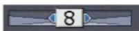
This figure shows the HSM slider:
16.3.5 Procedure (HSM)
Follow this procedure to adjust an image using the HSM method:
- Turn the mode wheel

- Push the A/M button to select HSM. To change the sensitivity, move the joystick left/right.
You will need to experiment with this setting until you get a clear image of a verified gap leak.
16.3.6 Procedure (Manual)
Follow this procedure to adjust an image using the Manual method:
- Turn the mode wheel

-
Push the A/M button to select Manual, then do one of the following:
-
To change the temperature level, move the joystick up/down.
- To change the temperature span, move the joystick left/right.
16.4 Selecting a suitable temperature range
16.4.1 About temperature ranges
16.4.1.1 General
The camera has three different types of ranges. Within each type of range, there are several subranges. You must choose a suitable range for your object.
16.4.1.2 Types of temperature ranges
| Type | Name | Example Explanation | |
| 1 | Characteristic temperature range | -40^ to +350^ ( -40^ to +662^ ) | All temperatures the camera can register.This range is the total sum of the temperature ranges (type no. 2 below). |
| 2 Temperature range | +10^ to +50^ ( +50^ to +122^ ) | The span of temperatures that the camera can register with the current settings.This type of range is a subrange to type no. 1 above. | |
| 3 Temperature span | +23.8^ to +25.9^ ( +74.8^ to +78.6^ ) | The range of temperatures that the camera registers when aimed at a particular scene with a particular temperature range set. |
16.4.2 Understanding the temperature scale
16.4.2.1 Figure
16.4.2.2 Explanation
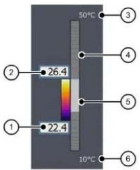
- Currently set minimum temperature in the temperature span (= range of type 3 in the table 16.4.1.2 Types of temperature ranges, page 48).
-
Currently set maximum temperature in the temperature span (= range of type 3 in the table 16.4.1.2 Types of temperature ranges, page 48).
-
Currently set maximum temperature in the range that the camera can register with the current settings (= range of type 2 in the table 16.4.1.2 Types of temperature ranges, page 48).
- Indicator that represents the temperature range (= range of type 2 in the table 16.4.1.2 Types of temperature ranges, page 48).
- Indicator that represents the temperature span (= range of type 3 in the table 16.4.1.2 Types of temperature ranges, page 48).
- Currently set minimum temperature in the range that the camera can register with the current settings (= range of type 2 in the table 16.4.1.2 Types of temperature ranges, page 48).
16.4.3 Changing the temperature range
16.4.3.1 Procedure
Follow this procedure to change the temperature range:
- Do one of the following:
- Push the temperature range button on the left side of the camera.
- Push the button, then select Adjust temp. range.
- Move the joystick up/down to choose a suitable temperature range for your object.
- Push the temperature range button to confirm and leave the setup mode.
16.5 Selecting a suitable color palette
16.5.1 Procedure
-
Turn the mode wheel to or
-
Push the button to display a menu.
-
Move the joystick left/right to go to the Image tab.
-
Move the joystick up/down to go to select Color palette.
-
Push the joystick to enable the list of palettes.
-
Move the joystick up/down to select a new palette.
-
Push the joystick.
-
Push the button to leave the setup mode.
16.6 Enabling or disabling histogram mode
16.6.1 General
Histogram mode is an image-displaying method that evenly distributes the color information over the existing temperatures of the image.
16.6.2 Procedure
-
Turn the mode wheel to or
-
Push the button to display a menu.
-
Move the joystick left/right to go to the Image tab.
-
Move the joystick up/down to go to select Histogram.
-
Push the joystick to enable/disable the setting.
-
Push the button to leave the setup mode.
16.7 Enabling or disabling inverted color palette
16.7.1 Procedure
- Turn the mode wheel
- Push the button to display a menu.
- Move the joystick left/right to go to the Image tab.
- Move the joystick up/down to go to select Invert palette.
- Push the joystick to enable/disable the setting.
- Push the button to leave the setup mode.
16.8 Changing object parameters
16.8.1 General
For accurate measurements, you must set the object parameters. You can do this locally or globally. This procedure describes how to change the object parameters globally.
16.8.2 Types of parameters
The camera can use these object parameters:
- Emissivity, i.e., how much radiation an object emits, compared to the radiation of a theoretical reference object of the same temperature (called a “blackbody”). The opposite of emissivity is reflectivity. The emissivity determines how much of the radiation originates from the object as opposed to being reflected by it.
- Reflected apparent temperature, which is used when compensating for the radiation from the surroundings reflected by the object into the camera. This property of the object is called reflectivity.
- Object distance, i.e., the distance between the camera and the object of interest.
- Atmospheric temperature, i.e., the temperature of the air between the camera and the object of interest.
- Relative humidity, i.e., the relative humidity of the air between the camera and the object of interest.
- External optics temperature, i.e., the temperature of any protective windows etc. that are set up between the camera and the object of interest. If no protective window or protective shield is used, this value is irrelevant.
- External optics transmission, i.e., the optical transmission of any protective windows, etc. that are set up between the camera and the object of interest.
16.8.3 Recommended values
If you are unsure about the values, the following values are recommended:
| Emissivity 0.95 | |
| Distance 1.0 m (3.3 ft.) | |
| Reflected apparent temperature | +20°C (+69°F) |
| Relative humidity 50% | |
| Atmospheric temperature | +20°C (+69°F) |
16.8.4 Procedure
Follow this procedure to change the object parameters globally:
- Turn the mode wheel to or
- Push the button to display a menu.
- Move the joystick left/right to go to the Edit tab.
- Move the joystick up/down to select Object parameters.
- Push the joystick to display a dialog box.
- Move the joystick up/down to select the parameter you want to change, then push the joystick.
- Move the joystick up/down to change the value, then push the joystick.
- Push the button to confirm and leave the setup mode.
Note
- Of the seven parameters above, emissivity and reflected apparent temperature are the two most important to set correctly in the camera.
- To change object parameters locally, first select a measurement tool in the toolbox, then select Use local parameters. Change the local parameters by selecting Edit local parameters, then edit them in the same way as for global object parameters.
16.8.5 Related topics
- For in-depth information about parameters, and how to correctly set emissivity and reflected apparent temperature, see 41 Thermographic measurement techniques.
Connecting external devices
17.1 General
You can connect the following external devices to the camera:
- A video monitor or projector, connected using an HDMI cable.
- A computer, to move images and other files to and from the camera.
• An SD memory card.
• An SDHC memory card.
The connectors for the external devices are protected by the connector and battery compartment cover. The cover is fastened with a Torx screw (T20).
Note Before operating the camera, you must read, understand, and follow the warnings, cautions, and notes in sections, page and 5 Conditions of Use for Ex Equipment, page 16.
17.2 Figure
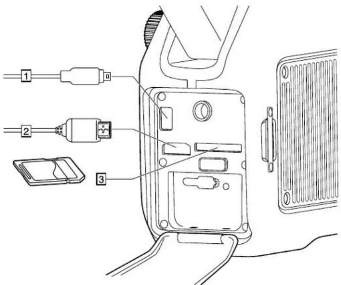
17.3 Explanation
- To connect a computer to the camera to move images and files to and from the camera, use a USB Mini-B cable and this connector.
- To play live video from the camera on an external video monitor using the HDMI protocol (High Definition Multimedia Interface), use an HDMI cable and this connector.
- To insert a memory card, use this card slot.
Note The connectors on the card must face down when inserting the card.
17.4 Formatting memory cards
For best performance, memory cards should be formatted to the FAT (FAT16) file system. Using FAT32-formatted memory cards may result in inferior performance. To format a memory card to FAT (FAT16), follow this procedure:
- Insert the memory card into a card reader that is connected to a computer running Microsoft Windows.
- In Windows Explorer, select My Computer and right-click the memory card.
- Select Format.
- Under File system, select FAT.
- Click Start.
Note
- SDHC memory cards that are 4 GB or larger can only be formatted to the FAT32 file system.
Handling the camera
18.1 Charging the camera battery

WARNING
Make sure that you install the socket-outlet near the equipment and that it is easy to get access to.
Note
- You must charge the battery for 4 hours before starting the camera for the first time. After that, you must charge the battery whenever a warning message for low battery power is displayed on the screen.
- The battery has a battery condition LED indicator. When the green LED glows continuously, the battery is fully charged.
- Charge the battery at room temperature.
18.1.1 Charging the battery using the power supply cable
18.1.1.1 Procedure
Follow this procedure to charge the battery using the power supply cable:
- Before operating the camera, you must read, understand, and follow the warnings, cautions, and notes in sections, page and 5 Conditions of Use for Ex Equipment, page 16.
- Remove the battery from the camera.
- Connect the power supply cable plug to the connector on the battery. The connector is protected by a rubber cover.
- Connect the power supply wall plug to a mains supply.
- When the green LED of the battery condition indicator glows continuously, disconnect the power supply cable.
18.1.1.2 Related topics
- For information about the battery condition LED indicator, see 14.5 Battery condition LED indicator, page 41.
- For information on how to install and remove the battery, see 18.2.1 Installing the battery, page 55 and 18.2.2 Removing the battery, page 56.
18.1.2 Charging the battery using the stand-alone battery charger
18.1.2.1 Procedure
Follow this procedure to charge the battery using the stand-alone battery charger:
- Before operating the camera, you must read, understand, and follow the warnings, cautions, and notes in sections, page and 5 Conditions of Use for Ex Equipment, page 16.
- Put the battery in the stand-alone battery charger.
- Connect the power supply cable plug to the connector on the stand-alone battery charger.
- Connect the power supply wall plug to a mains supply.
- When the green LED of the battery condition indicator glows continuously, disconnect the power supply cable.
18.1.2.2 Related topics
- For information about the battery condition LED indicator, see 14.5 Battery condition LED indicator, page 41.
- For information on how to install and remove the battery, see 18.2.1 Installing the battery, page 55 and 18.2.2 Removing the battery, page 56.
18.2 Installing and removing the camera battery
18.2.1 Installing the battery
Note Use a clean, dry cloth to remove any water or moisture on the battery before you install it.
18.2.1.1 Procedure
Follow this procedure:
-
Before operating the camera, you must read, understand, and follow the warnings, cautions, and notes in sections, page and 5 Conditions of Use for Ex Equipment, page 16.
-
Unscrew the Torx T20 screw and open the battery compartment cover.
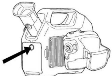
natural_image
Line drawing of a DSLR camera with an arrow pointing to the left side (no text or symbols present)- Push the battery into the battery compartment. The battery makes a click when it locks in place.
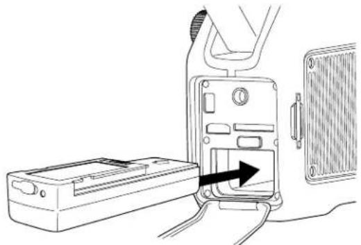
natural_image
Line drawing of a device with an open box and cable, showing internal components and a hand holding a cable (no text or symbols)- Close the cover and tighten the Torx T20 screw to 80 N cm.
18.2.2 Removing the battery
18.2.2.1 Procedure
Follow this procedure:
-
Before operating the camera, you must read, understand, and follow the warnings, cautions, and notes in sections, page and 5 Conditions of Use for Ex Equipment, page 16.
-
Turn off the camera.
-
Unscrew the Torx T20 screw and open the battery compartment cover.
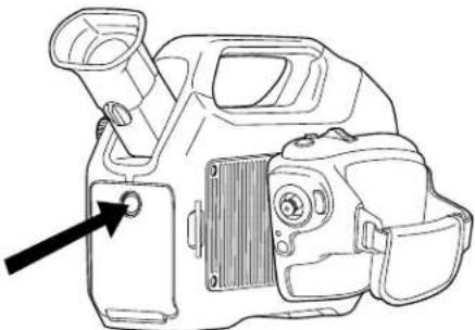
natural_image
Line drawing of a digital camera with an arrow pointing to the button (no text or symbols present)- Push the release button for the battery.
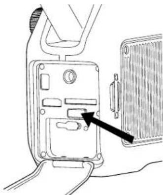
natural_image
Line drawing of a device panel with an arrow pointing to a component (no text or symbols present)- Pull out the battery from the battery compartment.
18.3 Turning on the camera
18.3.1 Procedure
To turn on the camera, push and release button.
Note
- The mechanical cooler has a sound that resembles a subdued motor. This sound is normal. When the cooling procedure is completed, there is a distinct change in the sound.
- The cooling procedure typically takes 7 minutes. At high ambient temperatures the cooling time may increase 30% or more.
18.4 Turning off the camera
18.4.1 Procedure
To turn off the camera, push and hold the button until the progress bar that is displayed on the screen reaches the end.
18.5 Adjusting the viewing angle of the viewfinder
18.5.1 General
To make your working position as comfortable as possible, you can adjust the viewing angle of the viewfinder.
18.5.2 Figure
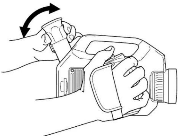
natural_image
Line drawing of hands using a handheld device to interact with a device (no text or symbols present)18.5.3 Procedure
To adjust the viewfinder, tilt the viewfinder up or down.
18.6 Adjusting the viewfinder's dioptric correction
18.6.1 General
The viewfinder's dioptric correction can be adjusted for your eyesight.
18.6.2 Figure
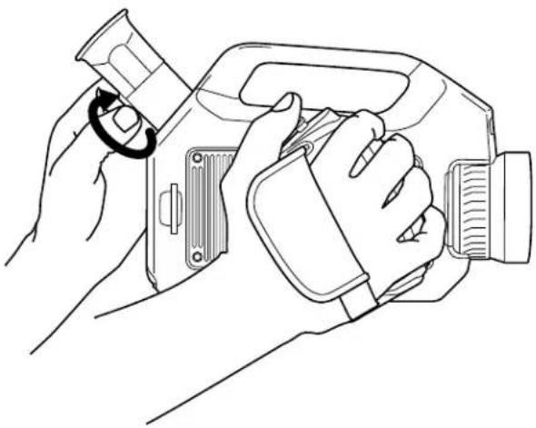
natural_image
Line drawing of hands operating a handheld device with a circular component (no text or symbols)18.6.3 Procedure
To adjust the viewfinder's dioptric correction, look at the displayed text or graphics on the screen and rotate the adjustment knob clockwise or counter-clockwise for best sharpness.
Note
• Maximum dioptric correction: +2
• Minimum dioptric correction: -2
18.7 Adjusting the camera grip
18.7.1 General
To make your working position as comfortable as possible, you can adjust the angle of the camera grip.
18.7.2 Figure
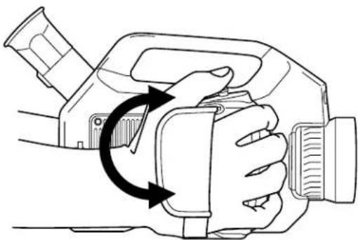
natural_image
Line drawing of a hand operating a camera with a circular arrow indicating rotational motion (no text or symbols)18.7.3 Procedure
To adjust the camera grip, rotate the camera grip clockwise or counter-clockwise.
18.8 Opening the display
18.8.1 Figure
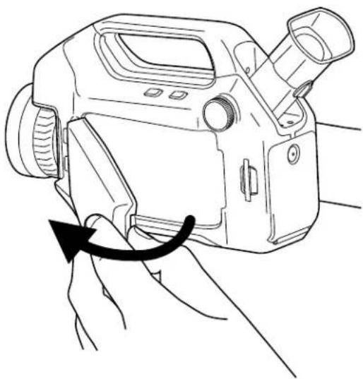
natural_image
Line drawing of a digital camera with a hand adjusting the lens (no text or symbols)18.9 Adjusting the viewing angle of the display
18.9.1 General
To make your working position as comfortable as possible, you can adjust the viewing angle of the display.
18.9.2 Figure
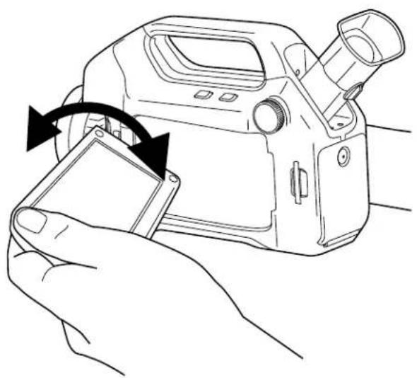
natural_image
Line drawing of a hand holding a digital camera with an arrow indicating rotation (no text or symbols)18.9.3 Procedure
To adjust the viewing angle of the display, rotate the display clockwise or counterclockwise.
18.10 Adjusting the infrared camera focus
Note Do not touch the lens surface when you adjust the infrared camera focus. If this happens, clean the lens according to the instructions in 35.2 Infrared lens, page 108.
18.10.1 Figure
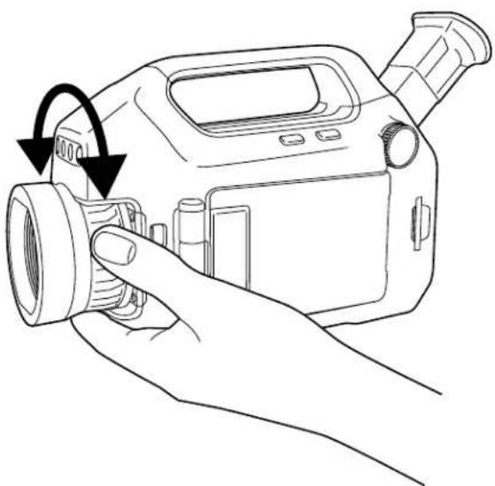
natural_image
Line drawing of a hand holding a digital camera with an arrow indicating rotation (no text or symbols)18.10.2 Procedure
Do one of the following:
- For far focus, rotate the focus ring counter-clockwise (looking at the front of the lens)
- For near focus, rotate the focus ring clock-wise (looking at the front of the lens)
18.11 Using the zoom function
18.11.1 General
You can zoom in on infrared images in preview or archive mode. This enables you to view details in an image.
18.11.2 Procedure
Do one of the following:
- To zoom into or out of a live image, choose Zoom on the second tab in the menu system, then use the joystick.
- To zoom into or out of an image in preview or archive mode, put ZOOM button left/right.
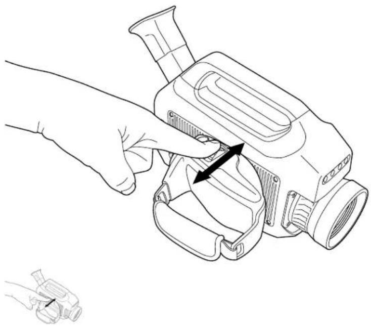
natural_image
Line drawing of a hand holding a digital camera with an arrow indicating the grip (no text or symbols present)18.12 Operating the laser pointer
18.12.1 Figure
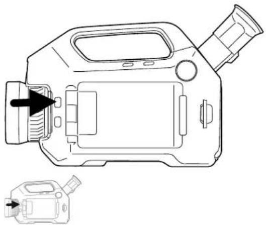
natural_image
Line drawing of a vintage camera with a left-side inset showing internal components (no text or symbols)18.12.2 Procedure
Follow this procedure to operate the laser pointer:
- To turn on the laser pointer, push and hold the laser button.
- To turn off the laser pointer, release the laser button.

WARNING
Do not look directly into the laser beam. The laser beam can cause eye irritation.
Note The symbol ⚠️ is displayed on the screen when the laser pointer is on.
18.13 Laser warning label
A laser warning label with the following information is affixed to the camera:
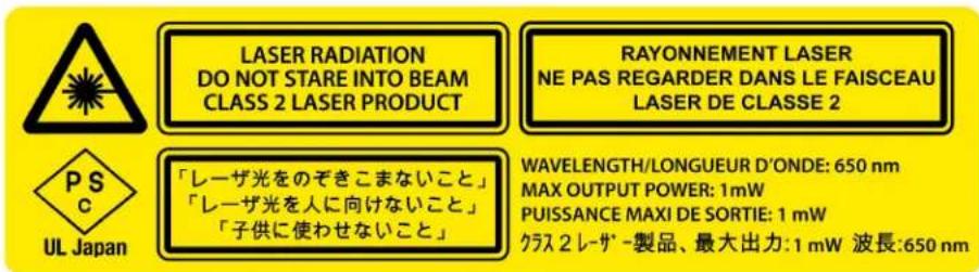
18.14 Laser rules and regulations
Wavelength: 635 nm. Maximum output power: 1 mW.
This product complies with 21 CFR 1040.10 and 1040.11 except for deviations pursuant to Laser Notice No. 50, dated June 24, 2007.
18.15 Assigning functions to the programmable button
18.15.1 General
The camera has a programmable button. You can assign one of the following functions to the programmable button:
- Change the zoom factor.
- Hide/show graphics.
- Change the polarity.
- Change the palette.
18.15.2 Procedure
Follow this procedure:
- Turn the mode wheel to enter setup mode.
- Select the Preferences tab and push the joystick.
- Select Programmable button and push the joystick.
- Select one of the functions and push the joystick.
- To leave the setup mode, turn the mode wheel and select another mode.
Working with views and images
19.1 Saving infrared images
19.1.1 General
You can save one or more images to an SD Memory Card.
19.1.2 Image capacity
The approximate number of images that can be saved on an SD Memory Card is 2,000 per GB.
19.1.3 Saving an infrared image directly to an SD Memory Card
19.1.3.1 General
You can save an image directly to an SD Memory Card, without previewing the image first.
19.1.3.2 Procedure
Follow this procedure to save an image directly to an SD Memory Card:
- Turn the mode wheel

- To save an image without previewing, push and hold a button for more than one second.
19.1.4 Previewing and saving an infrared image to an SD Memory Card
19.1.4.1 General
You can preview an image before you save it to an SD Memory Card. This lets you do or or more of the following tasks before you save the image:
- Edit measurements.
- Adjust the image.
- Add a digital photo.
- Delete an image.
19.1.4.2 Procedure
Follow this procedure to preview and save an image to an SD Memory Card:
- Turn the mode wheel

-
Push and release the S button. This will display a preview dialog box.
-
You can now do one or more of the following tasks before you save the image. Move the joystick to go to a task and push the joystick to select the task.
-
Select to edit measurement tools.
- Select + to adjust the image.
- Select to add a digital photo to the image. You turn on the digital camera lamps by pushing the joystick. Push the button to take a digital photo.
- Select to delete the image.
- Select H to save the image.
19.2 Opening an image
19.2.1 General
When you save an image, you store the image on an SD Memory Card. To display the image again, you can open it from the SD Memory Card.
19.2.2 Procedure
Follow this procedure to open an image:
- Turn the mode wheel to enter archive mode. This displays the archive overview or an image at full size.
-
In the archive overview, you can do the following:
-
Move the joystick up/down/left/right to select the image you want to view.
-
Push the joystick. This displays the selected image at full size.
-
When an image is displayed at full size, you can do the following:
-
Push the joystick or the button to edit the measurements, adjust the image, or delete the image. This displays a menu.
- Move the joystick left/right to view the previous/next image.
-
Move the joystick up to return to the archive overview.
-
To leave the archive mode, turn the mode wheel and select another mode.
19.3 Changing settings related to image presentation
19.3.1 General
In live mode, you can enable/disable a variety of settings relating to image presentation. These settings include:
- Zoom, i.e., zoom into or out of images.
- Hide/show graphics, i.e. hide or show the on-screen graphics.
-
Change the color palette, i.e. the colors that are used to display the temperatures in the infrared image.
-
Invert polarity, i.e. change the image polarity from white = hot to black = hot.
- Histogram equalization, i.e., an image-displaying method that evenly distributes the color information over the existing temperatures of the image.
Note In preview and archive mode, you can do the following related to image presentation:
ZOOM
- Push the ZOOM button left/right to zoom into or out of the image.
- Depending on the function you have assigned to the programmable button, you can hide/show graphics, change the polarity, or change the palette. For more information, see section 18.15 Assigning functions to the programmable button, page 62.
19.3.2 Procedure
- Turn the mode wheel


- Push the button to display a menu.
- Move the joystick left/right to go to the Image tab.
- Move the joystick up/down to go to select the setting that you want to change.
- Push the joystick to enable/disable the setting.
(If you select Zoom you can change the zoom factor by moving the joystick up/down.)
- Push the button to leave the setup mode.
19.4 Editing a saved image
19.4.1 General
You can edit a saved image. You can do one or more of the following tasks:
- Edit measurements.
- Adjust the image.
- Delete the image.
19.4.2 Procedure
Follow this procedure:
- Open the image at full size in the archive. For more information, see section 19.2 Opening an image, page 64.
- Push the joystick or the 📋. This displays a menu.
-
You can now do one or more of the following tasks. Move the joystick to go to a task and push the joystick to select the task.
-
Select to edit measurement tools.
- Select + to adjust the image.
Note You can only adjust an image that has been saved in Auto or Manual mode.
An image saved in HSM mode cannot be adjusted. For more information, see section 16.3 Adjusting an image, page 47.
- Select to delete the image.
- Select H to save any changes and exit edit mode.
19.5 Deleting a file
19.5.1 Procedure
Follow this procedure to delete an image file, a video clip, or a video sequence:
- Turn the mode wheel to enter archive mode. This displays the archive overview or an image at full size.
- If an image is displayed at full size, move the joystick up to go to the archive overview.
-
Move the joystick up/down/left/right to select the image you want to delete.
-
Push the button to display a menu.
-
Move the joystick up/down to select one of the following:
-
Delete
-
Delete all
-
Push the joystick.
-
Confirm the deletion and push the joystick.
Working with measurement tools
20.1 Laying out a measurement tool
20.1.1 General
To measure a temperature, you use one or several measurement tools, such as a spot-meter, a box, etc.
20.1.2 Procedure
Follow this procedure to lay out measurement tool:
- Turn the mode wheel to or
- Push the button to display a menu.
- Move the joystick left/right to go to the Edit tab.
- Move the joystick up/down to select the measurement tool you want to lay out.
- Push the joystick. The measurement tool has now been created on the screen.
20.2 Moving or resizing a measurement tool
20.2.1 General
You can move and resize a measurement tool.
20.2.2 Procedure
Note This procedure assumes that you have previously laid out a measurement tool on the screen.
Follow this procedure to move or resize a measurement tool:
- Turn the mode wheel to or
- Push the button to display a menu.
- Move the joystick left/right to go to the Edit tab.
- Move the joystick up/down to select the measurement tool that you want to move or resize.
- Push the joystick to display a menu.
- Move the joystick up/down to select Move or Resize.
- Move the joystick up/down and left/right to move or resize the measurement tool.
- Push the joystick to confirm.
- Push the button to leave the setup mode.
20.3 Creating & setting up a difference calculation
20.3.1 General
A difference calculation returns the difference between the values of two known measurement results, or between the value of a measurement result and the reference temperature.
20.3.2 Procedure
Note This procedure assumes that you have previously laid out at least two measurement tools on the screen.
Follow this procedure to create and set up a difference calculation:
-
Turn the mode wheel to or
-
Push the button to display a menu.
-
Move the joystick left/right to go to the Edit tab.
-
Move the joystick up/down to select Add difference.
-
Push the joystick to display a dialog box.
-
Do the following and push the joystick to confirm each choice:
6.1. To select the first function in the difference calculation, select Function 1 and push the joystick. Move the joystick up/down to select the measurement tool you want to use for this function.
6.2. (Not applicable if there is only one measurement tool.) To select the ID of the measurement tool, select Id and push the joystick. Move the joystick up/down to select the ID.
6.3. (Not applicable to spotmeter and reference temperature.) To select the result type of the measurement tool (Min., Max., Avg.), select Type and push the joystick. Move the joystick up/down to select the result type of the measurement tool.
- Do the following and push the joystick to confirm each choice:
7.1. To select the second function in the difference calculation, select Function 2 and push the joystick. Move the joystick up/down to select the measurement tool you want to use for this function.
7.2. (Not applicable if there is only one measurement tool.) To select the ID of the measurement tool, select Id and push the joystick. Move the joystick up/down to select the ID.
7.3. (Not applicable to spotmeter.) To select the result type of the measurement tool (Min., Max., Avg.), select Type and push the joystick. Move the joystick up/down to select the result type of the measurement tool.
- Push the button to confirm and leave the setup mode.
20.4 Changing object parameters
20.4.1 General
For accurate measurements, you must set the object parameters. You can do this locally or globally. This procedure describes how to change the object parameters globally.
20.4.2 Types of parameters
The camera can use these object parameters:
- Emissivity, i.e., how much radiation an object emits, compared to the radiation of a theoretical reference object of the same temperature (called a "blackbody"). The opposite of emissivity is reflectivity. The emissivity determines how much of the radiation originates from the object as opposed to being reflected by it.
- Reflected apparent temperature, which is used when compensating for the radiation from the surroundings reflected by the object into the camera. This property of the object is called reflectivity.
- Object distance, i.e., the distance between the camera and the object of interest.
- Atmospheric temperature, i.e., the temperature of the air between the camera and the object of interest.
- Relative humidity, i.e., the relative humidity of the air between the camera and the object of interest.
- External optics temperature, i.e., the temperature of any protective windows etc. that are set up between the camera and the object of interest. If no protective window or protective shield is used, this value is irrelevant.
- External optics transmission, i.e., the optical transmission of any protective windows, etc. that are set up between the camera and the object of interest.
20.4.3 Recommended values
If you are unsure about the values, the following values are recommended:
| Emissivity 0.95 | |
| Distance 1.0 m (3.3 ft.) | |
| Reflected apparent temperature | +20°C (+69°F) |
| Relative humidity 50% | |
| Atmospheric temperature | +20°C (+69°F) |
20.4.4 Procedure
Follow this procedure to change the object parameters globally:
- Turn the mode wheel
- Push the button to display a menu.
- Move the joystick left/right to go to the Edit tab.
- Move the joystick up/down to select Object parameters.
- Push the joystick to display a dialog box.
- Move the joystick up/down to select the parameter you want to change, then push the joystick.
- Move the joystick up/down to change the value, then push the joystick.
- Push the button to confirm and leave the setup mode.
Note
- Of the seven parameters above, emissivity and reflected apparent temperature are the two most important to set correctly in the camera.
- To change object parameters locally, first select a measurement tool in the toolbox, then select Use local parameters. Change the local parameters by selecting Edit local parameters, then edit them in the same way as for global object parameters.
20.4.5 Related topics
- For in-depth information about parameters, and how to correctly set emissivity and reflected apparent temperature, see 41 Thermographic measurement techniques.
21
Programming the camera
21.1 General
You can program the camera to save images periodically.
21.2 Procedure
Follow this procedure to make the camera save images periodically:
- Turn the mode wheel to . This will display the following dialog box:
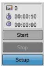
-
Move the joystick up/down to select Setup.
-
Push the joystick. This will display the following dialog box:
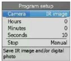
-
Push the joystick.
-
Use the joystick to set the following:
-
The type of images to save (IR image, Digital photo, IR and digital).
- The time period between which the camera will save an image (hours, minutes, seconds).
• The stop condition (timer, counter, manual) -
The timer or counter settings, if you selected one of these as stop condition.
-
Push the button.
- Move the joystick up/down to select Start.
- Push the joystick to start the periodic saving.
22.1 General
You can record infrared or visual video clips (*.mp4), as well as radiometric video sequence files (*.seq). In this mode, the camera can be regarded as an ordinary digital video camera. The video clips can be edited and played back in FLIR VideoReport.
*.seq video clips can also be handled and edited in FLIR Reporter.
22.2 Procedure
- Turn the mode wheel

-
Push the S button. The recording has now begun. A timer in the top right corner of the screen displays the elapsed recording time.
-
To stop the recording, push the button. This will display a preview dialog box.
-
You can now do one or more of the following tasks before you save the video clip.
-
Select to add a digital photo to the video clip. You turn on the digital camera lamps by pushing the joystick. Push button to take a digital photo.
- Select ▶ to play the video clip.
- Select to stop the playback of the video clip. This will also reset the playback counter to the beginning of the video clip.
- Select □ to pause/resume the playback of the video clip.
- Select to discard the video clip.
- Select H to keep the video clip.
Changing settings
23.1 General
You can change a variety of settings for the camera:
- Regional settings, such as language, date, time, etc.
- Camera settings, such as digital camera color, display intensity, etc.
- Preferences, such as user-configurable buttons, image overlay information, text size, etc. Here you can also set the camera to stamp the temperature scale into the image.
- Camera information, such as serial number, part number, used and free memory, etc. No changes are possible here, only presentation of information.
23.2 Procedure
Follow this procedure to change settings:
- Turn the mode wheel to enter setup mode.
- Move the joystick left/right to go to the desired tab.
- Move the joystick up/down to select the desired menu item.
- Push the joystick. This will highlight a setting (or display a submenu, depending on the context).
- Move the joystick up/down to change the setting.
-
Push the joystick to confirm the choice.
-
(To close a submenu, push the button.)
-
To leave the setup mode, turn the mode wheel and select another mode.
24
Technical data
Table of contents
24.1 Online field-of-view calculator.... 73
24.2 Note about technical data.... 73
24.3 Note about authoritative versions.... 73
24.4 FLIR GFx320 14.5° fixed lens....74
24.5 FLIR GFx320 24° fixed lens 79
24.1 Online field-of-view calculator
Please visit http://support.flir.com and click the photo of the camera series for field-of-view tables for all lens-camera combinations.
24.2 Note about technical data
FLIR Systems reserves the right to change specifications at any time without prior notice. Please check http://support.flir.com for latest changes.
24.3 Note about authoritative versions
The authoritative version of this publication is English. In the event of divergences due to translation errors, the English text has precedence.
Any late changes are first implemented in English.
24.4 FLIR GFx320 14.5° fixed lens
P/N: 74902-0101
Rev.: 41315
| General description |
| The FLIR GFx320 is an infrared camera for optical gas imaging (OGI) in explosive atmospheres that visualizes and pinpoints leaks of methane and other volatile organic compounds (VOCs), without the need to shut down the operation. The portable camera also greatly improves operator safety, by detecting emissions at a safe distance, and helps to protect the environment by tracing leaks of environmentally harmful gases.The FLIR GFx320 is used in industrial settings such as oil refineries, natural gas processing plants, offshore platforms, chemical/petrochemical industries, and biogas and power generation plants. |
| Benefits: |
| Certified for use in an explosive atmosphere.Improved efficiency: The FLIR GFx320 reduces revenue loss by pinpointing gas leaks quickly and efficiently, and from a distance. It also reduces the inspection time by allowing a broad area to be scanned rapidly and without the need to interrupt the industrial process. The FLIR GFx320 is also used for temperature measurement, which makes it even more useful for predictive maintenance.Increased worker safety: OGI allows gas leaks to be detected in a non-contact mode and from a safe distance. This reduces the risk of the user being exposed to invisible and potentially harmful or explosive chemicals. With a FLIR GFx320 gas imaging camera it is easy to scan areas of interest that are difficult to reach with conventional methods. The camera is ergonomically designed, with a bright LCD and tiltable viewfinder, which facilitates its use over a full working day.Protecting the environment: Several VOCs are dangerous to human health or cause harm to the environment, and are usually governed by regulations. Even small leaks can be detected and documented using the FLIR GFx320 camera. |
| Detects the following gases: benzene, ethanol, ethylbenzene, heptane, hexane, isoprene, methanol, MEK, MIBK, octane, pentane, 1-pentene, toluene, xylene, butane, ethane, methane, propane, ethylene, propylene. |
| Imaging and optical data | |
| IR resolution 320 × 240 pixels | |
| Thermal sensitivity/NETD <15 mK @ +30°C (+86°F) | |
| Field of view (FOV) | 14.5° × 10.8° |
| Minimum focus distance 0.5 m (1.64 ft.) | |
| Focal length 38 mm (1.49 in.) | |
| F-number 1.5 | |
| Focus Manual focus | |
| Zoom | 1-8x continuous, digital zoom |
| Digital image enhancement | Noise reduction filter, high sensitivity mode (HSM) |
| Detector data | |
| Detector type | Focal plane array (FPA), cooled InSb |
| Spectral range | 3.2–3.4 μm |
| Detector pitch | 30 μm |
| Sensor cooling | Stirling Microcooler (FLIR MC-3) |
| Detects following gases | Benzene, Ethanol, Ethylbenzene, Heptane, Hexane, Isoprene, Methanol, MEK, MIBK, Octane, Pentane, 1-Pentene, Toluene, Xylene, Butane, Ethane, Methane, Propane, Ethylene, Propylene |
| Electronics and data rate | |
| Full frame rate 60 Hz | |
| Image presentation | |
| Display Built-in widescreen, 4.3 in. LCD, 800 × 480 pixels | |
| Viewfinder Built-in, tiltable OLED, 800 × 480 pixels | |
| Automatic image adjustment Continuous/manual; linear or histogram based | |
| Manual image adjustment Level/span | |
| Image presentation modes | |
| Image modes IR image, visual image, high sensitivity mode (HSM) | |
| Measurement | |
| Temperature range -20°C to +350°C (-4°F to +62°F) | |
| Accuracy | ±1°C (±1.8°F) for temperature range (0°C, to +100°C, +32°F to +212°F) or ±2% of reading for temperature range (>+100°C, >+212°F) |
| Measurement analysis | |
| Spotmeter | 10 |
| Area 5 boxes with max./min./average | |
| Profile 1 live line (horizontal or vertical) | |
| Difference temperature Delta temperature between measurement functions or reference temperature | |
| Reference temperature | Manually set or captured from any measurement function |
| Emissivity correction | Variable from 0.01 to 1.0 or selected from edita materials list |
| Reflected apparent temperature correction | Automatic, based on input of reflected tempera |
| Measurement corrections | Reflected temperature, distance, atmospheric transmission, humidity, external optics |
| Set-up | |
| Menu commands | Level, spanAuto adjust continuous/manual/semi-automaticZoomPaletteStart/stop recordingStore imagePlayback/recall image |
| Color palettes | IronGrayRainbowArcticLavaRainbow HC |
| Set-up commands | 1 programmable button, overlay recording mode, local adaptation of units, language, date and time formats |
| Storage of Images | |
| Storage media Removable SD or SDHC memory | card |
| Image storage capacity 2000 images (JPEG) with | post process capability per GB on memory card |
| Image storage mode | • IR/visual images• Visual image can automatically be associated with corresponding IR image |
| Periodic image storage Every 10 seconds up to | 24 hours |
| File formats Standard JPEG, 14 bit measurement | data included |
| Geographic Information System | |
| GPS | Location data automatically added to every image from built-in GPS |
| Video recording in camera | |
| Radiometric IR video recording *.seq video clips | to memory card (7.5 and 15 Hz). |
| Non-radiometric IR video recording | • MPEG4 (up to 60 minutes/clip) to memory card• Visual image can automatically be associated with corresponding recording of non-radiometric IR video. |
| Visual video recording MPEG4 (25 minutes/clip) to memory card | |
| Video streaming | |
| Radiometric IR video streaming | Full dynamic to PC using USB cable. PC software capable of displaying the video stream include the following:• FLIR IR Camera Player• FLIR ResearchIR• FLIR Tools |
| Non-radiometric IR video streaming | RTP/MPEG4 |
| Digital camera | |
| Built-in digital camera 3.2 Mpixels, auto focus, and two video lamps | |
| Laser pointer | |
| Laser Activated by dedicated button | |
| Laser classification | Class 2 |
| Laser type | Semiconductor AlGaInP diode laser, 1 mW, 635 nm (red) |
| USB | |
| USB | USB Mini-B: Data transfer to and from PC |
| USB, standard | USB Mini-B: 2.0 high speed |
| Composite video | |
| Video out | Digital video output (image) |
| Power system | |
| Battery type | Rechargeable Li ion battery |
| Battery voltage | 7.2 V |
| Power system | |
| Battery capacity 4.4 Ah | |
| Battery operating time >3 hours at 25°C (+68°F) and typical use | |
| Charging system In camera (AC adapter or 12 V) | from a vehicle) or 2-bay charger |
| Charging time | 2.5 h to 95% capacity, charging status indicated LED's |
| Charging temperature 0°C to +45°C (+32°F to + | 13°F), except for the Korean market: +10°C to +45°C (+50°F to +113°F) |
| External power operation AC adapter 90–260 VAC | 50/60 Hz or 12 V from a vehicle (cable with standard plug, optional) |
| DC operation 8 to 15.3 V DC, polarity protected | (proprietary protected) |
| Power 8.5 W typically | |
| Start-up time Typically 7 min. @ 25°C (+77°F) | |
| Environmental data | |
| Operating temperature range -20°C to +50°C (-4°F to +122°F) | |
| Ambient temperature range (certification range for explosive atmospheres) | -20°C to +40°C (-4°F to +104°F) |
| Storage temperature range -30°C to +60°C (-22°F to +140°F) | |
| Humidity (operating and storage) | IEC 68-2-30/24 h 95% relative humidity +25°C +40°C (+77°F to +104°F) (2 cycles) |
| Explosive (hazardous) environment | IEC 60079-0:2011IEC 60079-11:2011IEC 60079-15:2010 (partial)IEC 60079-28:2015BS EN 60079-0:2012BS EN 60079-11:2012BS EN 60079-15:2010BS EN 60079-28:2015ANSI/ISA-12.12.01-2013CSA 22.2 No. 213ATEX directive 2014/34/EU |
| Low voltage | 73/23/EEC |
| RoHS | 2011/65/EU |
| WEEE | 2012/19/EU |
| EMC | The Electromagnetic Compatibility (EMC) Directive 2014/30/EUEN61000-6-4 (Emission)EN61000-6-2 (Immunity)FCC 47 CFR Part 15 class A (Emission)EN 61 000-4-8, L5 |
| Encapsulation | IP 54 (IEC 60529) |
| Shock 25 g (IEC 60068-2-27) | |
| Vibration | 2 g (IEC 60068-2-6) |
| Safety | EN/UL/IEC 60950-1 |
| Physical data | |
| Camera weight, incl. battery 2.80 kg (6.18 lbs.) | |
| Camera weight, excl. battery 2.59 kg (5.71 lbs.) | |
| Battery weight 0.21 kg (0.47 lbs.) | |
| Camera size (L × W × H) 245 × 166 × 164 mm | (9.6 × 6.5 × 6.4 in.) |
| Battery size (L × W × H) 141 × 43 × 28 mm (5.5 × 1.7 × 1.1 in.) | |
| Battery charger size (L × W × H) 158 × 122 × 25 mm (6.2 × 4.8 × 1.0 in.) | |
| Tripod mounting | UNC 1⁄4"-20 |
| Housing material Aluminum, magnesium, silicone | |
| Certifications | |
| Compliance | ATEX/IECEx, Ex ic nC op is IIC T4 GcII 3 GANSI/ISA-12.12.01-2013, Class I Division 2CSA 22.2 No. 213, Class I Division 2 |
| Shipping information | |
| Packaging, type | Cardboard box |
| List of contents | Battery chargerBattery, 2 ea.Hand strapHard transport caseHDMI-DVI cableHDMI-HDMI cableInfrared camera with lensLens cap (mounted on lens)Lens cap strapMemory cardNeck strapPower supply, incl. multi-plugsPrinted documentationScrewdriver TX20USB cable |
| EAN-13 | 7332558012574 |
| UPC-12 | 845188013721 |
| Course organization | |
| ITC | |
| ITC Trainers and Licensed Trainers | |
• T197692; Battery charger, incl. power supply with multi plugs
• T910814; Power supply, incl. multi plugs
• T911650ACC; Memory card SD Card 8 GB
• 1910423; USB cable Std A <-> Mini-B
• T198509; Cigarette lighter adapter kit, 12 VDC, 1.2 m/3.9 ft.
• T910815ACC; HDMI to HDMI cable 1.5 m
• T910816ACC; HDMI to DVI cable 1.5 m
• T129739ACC; Lens cap
• T129867ACC; Lens cap strap
• T129729ACC; Neck strap
• T129728ACC; Hand strap
• T911309ACC; Screwdriver TX20
24.5 FLIR GFx320 24° fixed lens
P/N: 74902-0102
Rev.: 41314
| General description |
| The FLIR GFx320 is an infrared camera for optical gas imaging (OGI) in explosive atmospheres that visualizes and pinpoints leaks of methane and other volatile organic compounds (VOCs), without the need to shut down the operation. The portable camera also greatly improves operator safety, by detecting emissions at a safe distance, and helps to protect the environment by tracing leaks of environmentally harmful gases.The FLIR GFx320 is used in industrial settings such as oil refineries, natural gas processing plants, offshore platforms, chemical/petrochemical industries, and biogas and power generation plants. |
| Benefits: |
| Certified for use in an explosive atmosphere.Improved efficiency: The FLIR GFx320 reduces revenue loss by pinpointing gas leaks quickly and efficiently, and from a distance. It also reduces the inspection time by allowing a broad area to be scanned rapidly and without the need to interrupt the industrial process. The FLIR GFx320 is also used for temperature measurement, which makes it even more useful for predictive maintenance.Increased worker safety: OGI allows gas leaks to be detected in a non-contact mode and from a safe distance. This reduces the risk of the user being exposed to invisible and potentially harmful or explosive chemicals. With a FLIR GFx320 gas imaging camera it is easy to scan areas of interest that are difficult to reach with conventional methods. The camera is ergonomically designed, with a bright LCD and tiltable viewfinder, which facilitates its use over a full working day.Protecting the environment: Several VOCs are dangerous to human health or cause harm to the environment, and are usually governed by regulations. Even small leaks can be detected and documented using the FLIR GFx320 camera. |
| Detects the following gases: benzene, ethanol, ethylbenzene, heptane, hexane, isoprene, methanol, MEK, MIBK, octane, pentane, 1-pentene, toluene, xylene, butane, ethane, methane, propane, ethylene, propylene. |
| Imaging and optical data | |
| IR resolution 320 × 240 pixels | |
| Thermal sensitivity/NETD <15 mK @ +30°C (+86°F) | |
| Field of view (FOV) | 24° × 18° |
| Minimum focus distance 0.3 m (1.0 ft.) | |
| Focal length 23 mm (0.89 in.) | |
| F-number 1.5 | |
| Focus Manual focus | |
| Zoom | 1-8× continuous, digital zoom |
| Digital image enhancement | Noise reduction filter, high sensitivity mode (HSI) |
| Detector data | |
| Detector type | Focal plane array (FPA), cooled InSb |
| Spectral range | 3.2–3.4 μm |
| Detector pitch | 30 μm |
| Sensor cooling | Stirling Microcooler (FLIR MC-3) |
| Detects following gases | Benzene, Ethanol, Ethylbenzene, Heptane, Hexane, Isoprene, Methanol, MEK, MIBK, Octane, Pentane, 1-Pentene, Toluene, Xylene, Butane, Ethane, Methane, Propane, Ethylene, Propylene |
| Electronics and data rate | |
| Full frame rate 60 Hz | |
| Image presentation | |
| Display Built-in widescreen, 4.3 in. LCD, 800 × 480 pixels | |
| Viewfinder Built-in, tiltable OLED, 800 × 480 pixels | |
| Automatic image adjustment Continuous/manual; linear or histogram based | |
| Manual image adjustment Level/span | |
| Image presentation modes | |
| Image modes IR image, visual image, high sensitivity mode (HSM) | |
| Measurement | |
| Temperature range -20°C to +350°C (-4°F to +62°F) | |
| Accuracy | ±1°C (±1.8°F) for temperature range (0°C, to +100°C, +32°F to +212°F) or ±2% of reading for temperature range (>+100°C, >+212°F) |
| Measurement analysis | |
| Spotmeter | 10 |
| Area 5 boxes with max./min./average | |
| Profile 1 live line (horizontal or vertical) | |
| Difference temperature Delta temperature between measurement functions or reference temperature | |
| Reference temperature | Manually set or captured from any measurement function |
| Emissivity correction | Variable from 0.01 to 1.0 or selected from edita materials list |
| Reflected apparent temperature correction | Automatic, based on input of reflected tempera |
| Measurement corrections | Reflected temperature, distance, atmospheric transmission, humidity, external optics |
| Set-up | |
| Menu commands | Level, spanAuto adjust continuous/manual/semi-automaticZoomPaletteStart/stop recordingStore imagePlayback/recall image |
| Color palettes | IronGrayRainbowArcticLavaRainbow HC |
| Set-up commands | 1 programmable button, overlay recording mode, local adaptation of units, language, date and time formats |
| Storage of Images | |
| Storage media Removable SD or SDHC memory | card |
| Image storage capacity 2000 images (JPEG) with | post process capability per GB on memory card |
| Image storage mode | • IR/visual images• Visual image can automatically be associated with corresponding IR image |
| Periodic image storage Every 10 seconds up to | 24 hours |
| File formats Standard JPEG, 14 bit measurement | data included |
| Geographic Information System | |
| GPS | Location data automatically added to every image from built-in GPS |
| Video recording in camera | |
| Radiometric IR video recording *.seq video clips | to memory card (7.5 and 15 Hz). |
| Non-radiometric IR video recording | • MPEG4 (up to 60 minutes/clip) to memory card• Visual image can automatically be associated with corresponding recording of non-radiometric IR video. |
| Visual video recording MPEG4 (25 minutes/clip) to memory card | |
| Video streaming | |
| Radiometric IR video streaming | Full dynamic to PC using USB cable. PC software capable of displaying the video stream include the following:• FLIR IR Camera Player• FLIR ResearchIR• FLIR Tools |
| Non-radiometric IR video streaming | RTP/MPEG4 |
| Digital camera | |
| Built-in digital camera 3.2 Mpixels, auto focus, and two video lamps | |
| Laser pointer | |
| Laser Activated by dedicated button | |
| Laser classification | Class 2 |
| Laser type | Semiconductor AlGaInP diode laser, 1 mW, 635 nm (red) |
| USB | |
| USB | USB Mini-B: Data transfer to and from PC |
| USB, standard | USB Mini-B: 2.0 high speed |
| Composite video | |
| Video out | Digital video output (image) |
| Power system | |
| Battery type | Rechargeable Li ion battery |
| Battery voltage | 7.2 V |
| Power system | |
| Battery capacity 4.4 Ah | |
| Battery operating time >3 hours at 25°C (+68°F) and typical use | |
| Charging system In camera (AC adapter or 12 V) | from a vehicle) or 2-bay charger |
| Charging time | 2.5 h to 95% capacity, charging status indicated LED's |
| Charging temperature 0°C to +45°C (+32°F to + | 13°F), except for the Korean market: +10°C to +45°C (+50°F to +113°F) |
| External power operation AC adapter 90–260 VAC | 50/60 Hz or 12 V from a vehicle (cable with standard plug, optional) |
| DC operation 8 to 15.3 V DC, polarity protected | (proprietary protected) |
| Power 8.5 W typically | |
| Start-up time Typically 7 min. @ 25°C (+77°F) | |
| Environmental data | |
| Operating temperature range -20°C to +50°C (-4°F to +122°F) | |
| Ambient temperature range (certification range for explosive atmospheres) | -20°C to +40°C (-4°F to +104°F) |
| Storage temperature range -30°C to +60°C (-22°F to +140°F) | |
| Humidity (operating and storage) | IEC 68-2-30/24 h 95% relative humidity +25°C +40°C (+77°F to +104°F) (2 cycles) |
| Explosive (hazardous) environment | IEC 60079-0:2011IEC 60079-11:2011IEC 60079-15:2010 (partial)IEC 60079-28:2015BS EN 60079-0:2012BS EN 60079-11:2012BS EN 60079-15:2010BS EN 60079-28:2015ANSI/ISA-12.12.01-2013CSA 22.2 No. 213ATEX directive 2014/34/EU |
| Low voltage | 73/23/EEC |
| RoHS | 2011/65/EU |
| WEEE | 2012/19/EU |
| EMC | The Electromagnetic Compatibility (EMC) Directive 2014/30/EUEN61000-6-4 (Emission)EN61000-6-2 (Immunity)FCC 47 CFR Part 15 class A (Emission)EN 61 000-4-8, L5 |
| Encapsulation | IP 54 (IEC 60529) |
| Shock 25 g (IEC 60068-2-27) | |
| Vibration | 2 g (IEC 60068-2-6) |
| Safety | EN/UL/IEC 60950-1 |
| Physical data | |
| Camera weight, incl. battery 2.72 kg (6.00 lbs.) | |
| Camera weight, excl. battery 2.50 kg (5.51 lbs.) | |
| Battery weight 0.21 kg (0.47 lbs.) | |
| Camera size (L × W × H) 245 × 166 × 164 mm | (9.6 × 6.5 × 6.4 in.) |
| Battery size (L × W × H) 141 × 43 × 28 mm (5.5 × 1.7 × 1.1 in.) | |
| Battery charger size (L × W × H) 158 × 122 × 25 mm (6.2 × 4.8 × 1.0 in.) | |
| Tripod mounting | UNC 1⁄4"-20 |
| Housing material Aluminum, magnesium, silicone | |
| Certifications | |
| Compliance | ATEX/IECEx, Ex ic nC op is IIC T4 GcII 3 GANSI/ISA-12.12.01-2013, Class I Division 2CSA 22.2 No. 213, Class I Division 2 |
| Shipping information | |
| Packaging, type | Cardboard box |
| List of contents | Battery chargerBattery, 2 ea.Hand strapHard transport caseHDMI-DVI cableHDMI-HDMI cableInfrared camera with lensLens cap (mounted on lens)Lens cap strapMemory cardNeck strapPower supply, incl. multi-plugsPrinted documentationScrewdriver TX20USB cable |
| EAN-13 | 7332558012567 |
| UPC-12 | 845188013714 |
| Course organization | |
| ITC | |
| ITC Trainers and Licensed Trainers | |
• T197692; Battery charger, incl. power supply with multi plugs
• T910814; Power supply, incl. multi plugs
• T911650ACC; Memory card SD Card 8 GB
• 1910423; USB cable Std A <-> Mini-B
• T198509; Cigarette lighter adapter kit, 12 VDC, 1.2 m/3.9 ft.
• T910815ACC; HDMI to HDMI cable 1.5 m
• T910816ACC; HDMI to DVI cable 1.5 m
• T129739ACC; Lens cap
• T129867ACC; Lens cap strap
• T129729ACC; Neck strap
• T129728ACC; Hand strap
• T911309ACC; Screwdriver TX20
Mechanical drawings
[See next page]
GFx320 24 deg
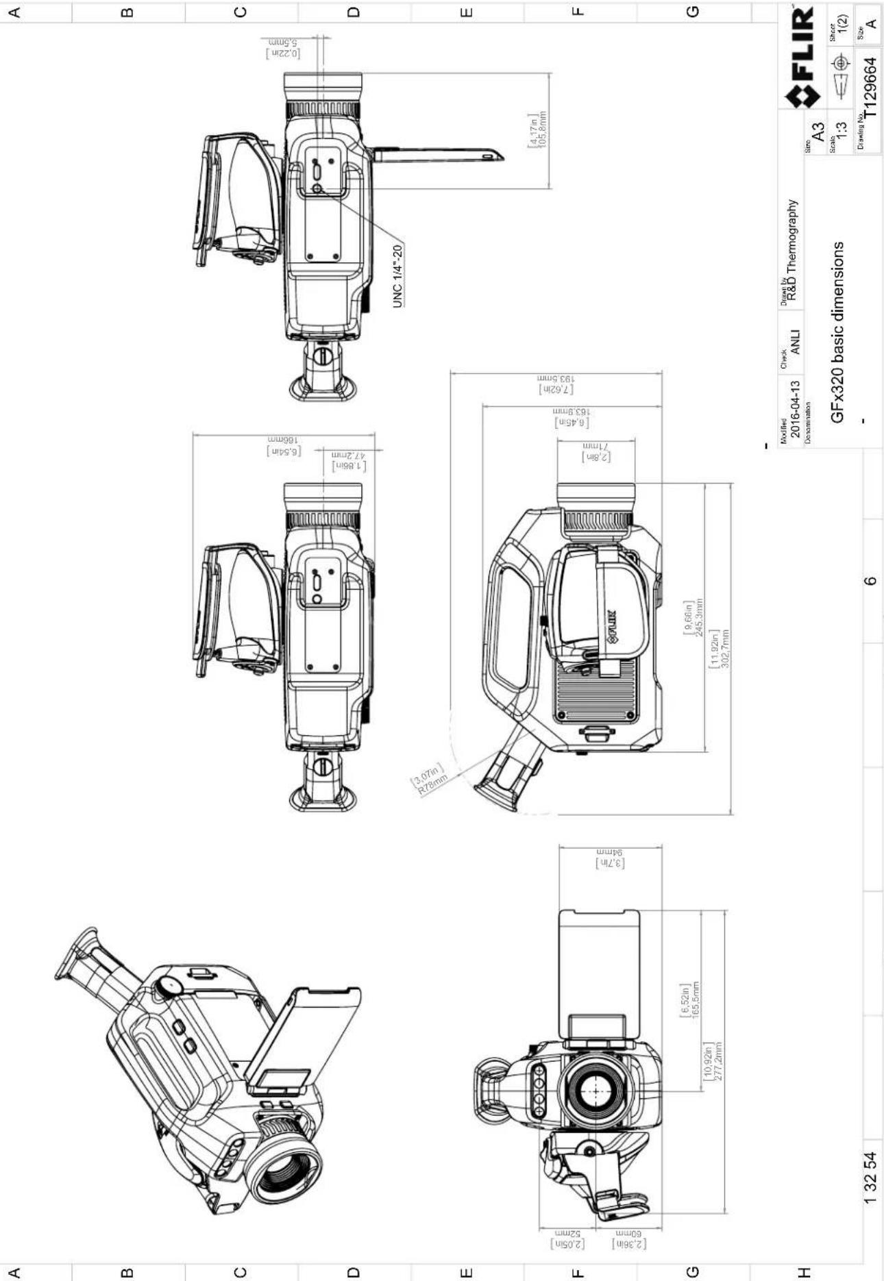
| Modified 2016-04-13 | Check ANLI | Drawn by R&D Thermography | ||
| Denomination GFx320 basic dimensions - | Size A3 | FLIR | ||
| Scale 1:3 | Sheet 1(2) | |||
| Drawing No. T129664 | Size A | |||
GFx320 14,5 deg
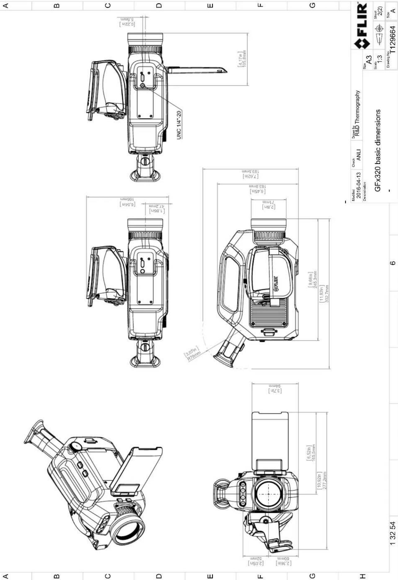
| Modified 2016-04-13 | Check ANLI | Drawn by R&D Thermography | ||
| Denomisation GFx320 basic dimensions - | Size A3 | |||
| Scale 1:3 | Sheet 2(2) | |||
| Drawing No. T129664 | Size A | |||
EU Declaration of conformity
[See next page]
EU Declaration of Conformity
This is to certify that the System listed below have been designed and manufactured to meet the requirements, as applicable, of the following EU-Directives and corresponding harmonising standards. The systems consequently meet the requirements for the CE-mark.
Directives:
2014/30/EU Electromagnetic Compatibility
2014/34/EU ATEX
2012/19/EU WEEE
Standards:
EN 61000-6-3
Emission
EN 61000-6-2
Immunity
EN 62133:2012
Safety – Batteries
IEC 60825-1
Safety - Laser
IEC 62471
Safety - Photobiological
EN 60950-1
Safety - General
BS EN 60079-0:2012+A11:2013
Explosive atmosphere - General
BS EN 60079-11:2012
Explosive atmosphere - Intrinsic
BS EN 60079-15:2010
Explosive atmosphere - Type n
BS EN 60079-28:2015
Explosive atmosphere - Optical
Notified Body
Element Materials Technology
0891 (Body no)
System:
FLIR GFx320
FLIR Systems AB
Quality Assurance
27
MET Compliance Data Report (truncated)
[See next page]
| Clause | Test |
| 22.5.2 | Before Seal Test Voltage Test (Component) |
| 22.5.1 | Conditioning (Component) |
| 22.5.3.2 | Seal Component Test (Component) Method 3 |
| 22.5.3.3 | After Seal Test Dielectric Test (Component) |
| N/A | Critical Drawings |
Compliance Test Data Report
Manufacturer/Applicant:
FLIR Systems AB
Antennvägen 6, 187 66 Täby, Sweden
/Element Materials Technology
Century Court Tolpits Lane Walford, Herts, UK WD18 9RS
Product description:
IDCA Component within the FLIR George Camera, Model GFx320.
Note: Testing will be with respect to EN/IEC 60079-15:2010 clause 22.5 as this testing is more onerous than ANSI/ISA 12.12.01:2012 and CSA/CAN C22.2 No. 213 (reaffirmed 2013) requirements.
CEIT# 17072-1: SB4293v2 (500-0525-00-07)
CEIT# 17072-2: SB4310v2 (500-0525-00-07)
CEIT# 17072-3: SB4275v2 (500-0525-00-07)
MET Laboratories, Inc.
13501 McCallen Pass
Austin, Texas 78753
(512) 287-2500
© Copyright 2016
The data in this report shall not be reproduced except in full, without the express written consent of MET Laboratories, Inc. Continued compliance or engineering data may not be used, interpreted, or presented as proof of compliance
28
IEC/IECEE/Intertek Test Report (truncated)
[See next page]
| TEST REPORTIEC 60950-1Information technology equipment – Safety –Part 1: General requirements | |
| Report Number......: 1517398STO-001Date of issue ......: 11 November 2016Total number of pages......: 76 pages | |
| Applicant's name ......: FLIR Systems ABAddress ......: Box 7376, SE-187 15 Täby, SWEDEN | |
| Test specification:Standard ......: IEC 60950-1:2005 (Second Edition) + Am 1:2009 + Am 2:2013Test procedure ......: CB SchemeNon-standard test method......: N/A | |
| Test Report Form No......: IEC60950_1FTest Report Form(s) Originator......: SGS Fimko LtdMaster TRF......: Dated 2014-02Copyright © 2014 IEC System of Conformity Assessment Schemes for Electrotechnical Equipment and Components (IECEE System). All rights reserved.This publication may be reproduced in whole or in part for non-commercial purposes as long as the IECEE is acknowledged as copyright owner and source of the material. IECEE takes no responsibility for and will not assume liability for damages resulting from the reader's interpretation of the reproduced material due to its placement and context.If this Test Report Form is used by non-IECEE members, the IECEE/IEC logo and the reference to the CB Scheme procedure shall be removed.This report is not valid as a CB Test Report unless signed by an approved CB Testing Laboratory and appended to a CB Test Certificate issued by an NCB in accordance with IECEE 02.TEST REPORT issued by an Accredited Testing Laboratory. Accredited by Swedac, no 1003, ISO/IEC 17025 | |
| General disclaimer:The test results presented in this report relate only to the object tested.This report shall not be reproduced, except in full, without the written approval of the Issuing CB Testing Laboratory. The authenticity of this Test Report and its contents can be verified by contacting the NCB, responsible for this Test Report. | |
| Test item description ......: Infrared Optical Gas Imaging CameraTrade Mark ......: FLIRManufacturer......:FLIR Systems ABModel/Type reference ......: FLIR GFX320Ratings......: 7.2VDC (battery operated), Class IIICLASS 2 LASER PRODUCT | |
| Testing procedure and testing location: | |
| ☒ CB Testing Laboratory: | Intertek Semko AB |
| Testing location/ address......: | Torshamnsgatan 43SE-164 40 Kista, SWEDEN |
| ☐ Associated CB Laboratory: | |
| Testing location/ address......: | |
| Tested by (name + signature)......: | Leif Söderlund |
| Approved by (name + signature)......: | Anna Karin Cedergren |
| ☐ Testing procedure: TMP | |
| Testing location/ address......: | |
| Tested by (name + signature)......: | |
| Approved by (name + signature)......: | |
| ☐ Testing procedure: WMT | |
| Testing location/ address......: | |
| Tested by (name + signature)......: | |
| Witnessed by (name + signature)......: | |
| Approved by (name + signature)......: | |
| ☐ Testing procedure: SMT | |
| Testing location/ address......: | |
| Tested by (name + signature)......: | |
| Approved by (name + signature)......: | |
| Supervised by (name + signature)...: | |
| ☐ Testing procedure: RMT | |
| Testing location/ address......: | |
| Tested by (name + signature)......: | |
| Approved by (name + signature)......: | |
| Supervised by (name + signature)...: | |
29
IEC/IECEE/Intertek CB Test Certificate
[See next page]
IEC SYSTEM FOR MUTUAL RECOGNITION OF TEST CERTIFICATES FOR ELECTRICAL EQUIPMENT (IECEE) CB SCHEME
CB TEST CERTIFICATE
| Product | Infrared Optical Gas Imaging Camera |
| Name and address of the applicant | FLIR Systems AB, Box 7376, 187 15 Täby, SWEDEN |
| Name and address of the manufacturer | Same as applicant |
| Name and address of the factoryNote: When more than one factory, please report on page 2 | FLIR Systems AB, Antennvägen 6, SE-187 66 Täby, SWEDEN |
| Ratings and principal characteristics | 7.2VDC (battery operated), Class III |
| Trademark (if any) | FLIR |
| Customer's Testing Facility (CTF) Stage used | - |
| Model / Type Ref. | FLIR GFX320 |
| Additional information (if necessary may also be reported on page 2) | See page 2 |
| A sample of the product was tested and found to be in conformity with | IEC 60950-1:2005+A1+A2(EN 60950-1:2006+A11+A1+A12+A2) |
| As shown in the Test Report Ref. No. which forms part of this Certificate | 1517398STO-001 |
This CB Test Certificate is issued by the National Certification Body
Intertek Semko AB
Box 1103
SE-164 22 Kista, Sweden
Int +46 8 750 00 00
Date: 11 November 2016
Intertek
Signature:
Bo Berglöf
Additional information (if necessary)
Common Modifications and Special National Conditions for CENELEC countries have been checked.
National differences for CA and US have also been checked during the testing.
CLASS 2 LASER PRODUCT
Refer to separate IEC 60825-1:2014 test report 1611196STO-001, issued by Intertek Semko AB
LED classification
Refer to separate IEC 62471:2006 test report 1611198STO-001, issued by Intertek Semko AB
END
Date: 11 November 2016
Signature:
30
MET Laboratories Test Certificate (truncated)
[See next page]
FLIR SYSTEMS AB, GFx320 Optical Gas Imaging Camera
Tested under
ANSI/ISA-12.12.01-2016 Nonincendive Electrical Equipment for Use in Class I and II, Division 2 and Class III, Divisions 1 and 2 Hazardous (Classified) Locations, Seventh Edition C22.2 NO. 213-16 – Nonincendive electrical equipment for use in Class I and II, Division 2 and Class III, Divisions 1 and 2 hazardous (classified) locations, Second Edition UL 60950-1/CSA-C22.2 NO. 60950-1 – Information Technology Equipment – Safety – Part 1: General Requirements, Second Edition
File: E114032
MET Report: 92286
Approved: Month, Date, Year
Applicant:
FLIR SYSTEMS AB
Antennvägen 6
SE-187 15 Täby
Sweden
Prepared By:
Element Materials Technology
Unit 1, Pendle Place
Skelmersdale, West Lancashire
WN8 9PN, UK
For:
MET Laboratories, Inc.
914 West Patapsco Avenue
Baltimore, Maryland 21230-3432
(410) 949-1802
This report shall not be reproduced except in full, without the express written consent of MET Laboratories, Inc.
☒ NRTL Listing MET-C Listing
□ MET Listing MET Listing for Canada
□ MET Recognition MET-C Recognition
□ MET Classification MET-C Classification
31
MET Laboratories Letter of Certification
[See next page]
December 13, 2016
FLIR Systems AB
Mr. Johan Eidefors
Antennvägen 6
PO Box 7376
SE-187 15
Täby, Sweden
Subject: FLIR Systems AB, GFx320 Optical Gas Imaging Camera
Listing Number E114032; MET Project Number 92286
Safety Standards: • UL 60950-1/CSA C22.2 No. 60950-1, Second Edition, Information Technology Equipment
• ANSI/ISA-12.12.01-2016 Nonincendive Electrical Equipment for Use in Class I and II, Division 2 and Class III, Divisions 1 and 2 Hazardous (Classified) Locations, Seventh Edition
- C22.2 NO. 213-16 – Nonincendive electrical equipment for use in Class I and II, Division 2 and Class III, Divisions 1 and 2 hazardous (classified) locations, Second Edition
Dear Mr. Eidefors:
Congratulations on successfully completing the MET Certification process for the GFx320 Optical Gas Imaging Camera. FLIR Systems AB may begin to apply the MET Mark on the previously identified product at this time in accordance with the MET Mark Utilization Agreement or the MET Applicant Contract. The report covering the above stated product is forthcoming.
Thank you for the opportunity to perform this service for FLIR Systems AB. We look forward to future opportunities with your company.
Sincerely.
MET LABORATORIES, INC.
Rick Cooper
Director,
Safety Business Line
The Nation's First Nationally Recognized Testing Laboratory MET Laboratories, Inc. is accredited by OSHA and the Standards Council of Canada.
Canadian Certification has been granted under a System 3 program as defined in ISO/IEC 17067.
NRTL
32
Element Type Examination Certificate (truncated)
[See next page]
1 TYPE EXAMINATION CERTIFICATE
2 Product or Protective System Intended for use in Potentially Explosive Atmospheres Directive 2014/34/EU – Annex VIII
3 Type Examination Certificate No.: EMT16ATEX0032X
4 Product: Optical Gas Imaging Camera, GFx320
5 Manufacturer: FLIR SYSTEMS AB,
6 Address: Antennvägen 6, SE-187 15 Täby, Sweden
7 This product and any acceptable variation thereto is specified in the schedule to this certificate and the documents therein referred to.
8 Element Materials Technology certifies that this product has been found to comply with the Essential Health and Safety Requirements relating to the design and construction of products intended for use in potentially explosive atmospheres given in Annex II to the Directive 2014/34/EU of the European Parliament and of the Council, dated 26 February 2014.
The examination and test results are recorded in the confidential report TRA-029115-33-00A.
9 Compliance with the Essential Health and Safety Requirements has been assured by compliance with:
EN 60079-0:2012/A11:2013 EN 60079-11:2012 EN 60079-15:2010
EN 60079-28:2015
Except in respect of those requirements listed at section 18 of the schedule.
10 If the sign "X" is placed after the certificate number, it indicates that the product is subject to specific conditions of use specified in the schedule to this certificate.
11 This TYPE EXAMINATION CERTIFICATE relates only to the design and construction of the specified product. Further requirements of the Directive apply to the manufacturing process and supply of this product. These are not covered by this certificate.
12 The marking of this product shall include the following:

II 3 G
Ex ic nC op is IIC T4 Gc
Rating: 8.4 V max , 7.2 V nom
This certificate and its schedules may only be reproduced in its entirety and without change. This certificate is issued in accordance with the Element Materials Technology Ex Certification Scheme.
S.P.Wisser
S P Winsor, Certification Manager
Issue date2016-12-07 Page 1 of 8 CSF356 4.0
33
IECEx Technical Report: GB/EMT/ExTR16.0015/00
[See next page]
IECEx Technical Report: GB/EMT/ExTR16.0015/00 details
| ExTR : | |
| ExTR Reference Number *: (automatic numbering) | GB/EMT/ExTR16.0015/00 |
| Status*: | Issued |
| ExTR Free Reference Number*: | TRA-029115-33-00A |
| Date of Issue*: (yyyy-mm-dd) | 2016-12-07 |
| List of Standards Covered*: | IEC 60079-0 (Ed.6.0); IEC 60079-11 (Ed.6.0); IEC 60079-15 (Ed.4); IEC 60079-28 (Ed.2) |
| Issuing ExTL*: | EMT - Element Materials Technology |
| Endorsing ExCB*: | EMT - Element Materials Technology |
| Manufacturer*: | FLIR SYSTEMS ABAntennvägen 6,SE-187 15 Täby, |
| Country of Manufacture*: | Sweden |
| Ex Protection*: | Intrinsic SafetyNon-Sparking |
| Ratings: | 8.4Vmax, 7.2Vnom (2s2p battery pack) |
| Equipment*: | Optical Gas Imaging Camera |
| Model Reference*: | GFx320 |
| Related IECEx Certificates: | IECEx EMT 16.0016X issue: 0 [Current] |
| Comment: | |
| Attachment: | |
34
IECEx Quality Assessment Report: GB/EMT/QAR16.0003/00
[See next page]
IECEx Quality Assessment Report: GB/EMT/QAR16.0003/00 details
| QAR : | |
| QAR Reference Number *:(automatic numbering) | GB/EMT/QAR16.0003/00 |
| Related QARs: | |
| Status*: | Issued |
| QAR Free Reference Number*: | TRA-029741-32-00A |
| Audit Date*:(yyyy-mm-dd) | 2016-09-06 |
| Date of Issue*:(yyyy-mm-dd) | 2016-10-14 |
| Valid until*:(yyyy-mm-dd) | 2019-09-05 |
| Site(s) audited*: | FLIR SYSTEMS AB,Antennvägen 6,SE-187 66 Täby,Sweden |
| Issuing ExCB*: | EMT - Element Materials Technology |
| Manufacturer*: | FLIR SYSTEMS AB,Antennvägen 6,SE-187 66 Täby, |
| Country of Manufacture*: | Sweden |
| Product information*: | No current certificate |
| Protection concept*: | No current certificate |
| Related IECEx Certificates:(automatic linking) | |
| Related Certificates:(manual insertion) | |
| Related IECEx Certificatesfor previous versions: | |
| Comment: | |
| Attachment: | |
Cleaning the camera
35.1 Camera housing, cables, and other items
35.1.1 Liquids
Use one of these liquids:
- Warm water
• A weak detergent solution
35.1.2 Equipment
A soft cloth
35.1.3 Procedure
Follow this procedure:
- Soak the cloth in the liquid.
- Twist the cloth to remove excess liquid.
- Clean the part with the cloth.

CAUTION
Do not apply solvents or similar liquids to the camera, the cables, or other items. This can cause damage.
35.2 Infrared lens
35.2.1 Liquids
Use one of these liquids:
- A commercial lens cleaning liquid with more than 30% isopropyl alcohol.
• 96% ethyl alcohol ( CH_5OH ).
35.2.2 Equipment
Cotton wool
| CAUTION |
| If you use a lens cleaning cloth it must be dry. Do not use a lens cleaning cloth with the liquids that are given in section 35.2.1 above. These liquids can cause material on the lens cleaning cloth to become loose.This material can have an unwanted effect on the surface of the lens. |
35.2.3 Procedure
Follow this procedure:
- Soak the cotton wool in the liquid.
- Twist the cotton wool to remove excess liquid.
- Clean the lens one time only and discard the cotton wool.
| WARNING |
| Make sure that you read all applicable MSDS (Material Safety Data Sheets) and warning labels on containers before you use a liquid: the liquids can be dangerous. |

CAUTION
- Be careful when you clean the infrared lens. The lens has a delicate anti-reflective coating.
- Do not clean the infrared lens too vigorously. This can damage the anti-reflective coating.
Cooler maintenance
36.1 General
The microcooler is designed to provide maintenance-free operation for many thousands of hours. The microcooler contains pressurized helium gas.
After several thousand hours of operation the gas pressure decreases, and cooler service is required to restore cooler performance. The cooler also contains micro ball bearings, which may exhibit wear by becoming louder.
36.2 Signs to watch for
The FLIR Systems microcooler is equipped with a closed-loop speed regulator, which adjusts the cooler motor speed to regulate the detector temperature.
Typically, the cooler runs at maximum speed for 7–10 minutes (depending on model), and then slows to about 40% of maximum speed. As the gas pressure degrades, the motor continues at maximum speed for longer and longer periods to attain operating temperature
Eventually, as the helium pressure decreases, the motor will lose the ability to achieve and/or maintain operating temperature. When this occurs, the camera must be returned to FLIR Systems Customer Service Department for service.
37.1 General
The FLIR GFx3xx camera has been engineered and designed to detect various gases, such as hydrocarbons. Within the laboratory, FLIR Systems has tested numerous gases for detection at varying concentrations.
37.2 Gases that can be detected by FLIR GFx3xx
| Common name Molecular formula Structural formula | ||
| 1-Pentene C | _5H_10 |  |
| Benzene C | _6H_6 |  |
| Butane C | _4H_10 |  |
| Ethane C | _2H_6 | — |
| Ethanol C | _2H_6O | 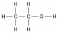 |
| Common name Molecular formula | Structural formula | |
| Ethylbenzene | C_8H_10 |  |
| Ethylene | C_2H_4 |  |
| Heptane C | _7H_16 |  |
| Hexane C | _6H_14 |  |
| Isoprene C | _5H_8 |  |
| m-Xylene C | _8H_10 |  |
| Methane CH | 4 |  |
| Methanol | CH_4O |  |
| Methyl ethyl ketone | C_4H_8O |  |
| MIBK C | _6H_10O |  |
| Octane C | _8H_18 |  |
| Pentane C | _5H_12 |  |
| Propane C | _3H_8 |  |
| Propylene | C_3H_6 |  |
| Toluene | C_7H_8 |  |
Why do some gases absorb infrared energy?
From a simplistic mechanical point of view, molecules in a gas could be compared to weights (the balls in the figures below), connected together via springs. Depending on the number of atoms, their respective size and mass, the elastic constant of the springs, molecules may move in given directions, vibrate along an axis, rotate, twist, stretch, rock, wag, etc.
The simplest gas molecules are single atoms, like helium, neon or krypton. They have no way to vibrate or rotate, so they can only move by translation in one direction at a time.
Figure 38.1 Single atom
The next most complex category of molecules is diatomic, made of two atoms such as hydrogen (H), nitrogen (M) and oxygen (O). They have the ability to tumble around their axes in addition to translational motion.
Figure 38.2 Two atoms
Then there are complex diatomic molecules, such as carbon dioxide) (C6H4) (CH4), sulfur hexafluoride (SF), and styrene (CH5CH=CH2) (these are just a few examples).
Figure 38.3 Simple mechanical model of carbon dioxide C 2 O 3 atoms per molecule
This assumption is valid for multi-atomic molecules.
chemical
Molecular structure of methane (CH₄) showing a central carbon atom bonded to four surrounding atomsFigure 38.4 Methane (CH), 5 atoms per molecule
Figure 38.5 Sulfur hexafluoride (Sf, 7 atoms per molecule
Figure 38.6 Molecular orbitals of Styrene (C5CH=CH2), 16 atoms per molecule
Their increased degrees of freedom allow multiple rotational and vibrational transitions. Because they are built from multiple atoms, they can absorb and emit heat more effectively than simple molecules. Depending on the frequency of the transitions, some of them fall into energy ranges that are located in the infrared region where the infrared camera is sensitive.
| Transition type Frequency | Spectral range | |
| Rotation of heavy molecules 10 | ^9-10^11 Hz Microwaves, above | 3 mm/0.118 in. |
| Rotation of light molecules and vibration of heavy molecules | 10^11-10^13 Hz Far infrared, between | 30 μm and 3 mm/0.118 in. |
| Vibration of light molecules. Rotation and vibration of the structure | 10^13-10^14 Hz Infrared, between | μm and 30 μm |
| Electronic transitions 10 | ^14-10^16 Hz UV-visible |
In order for a molecule to absorb or emit a photon via a transition from one state to another the molecule must have a dipole moment capable of briefly oscillating at the same frequency as the interacting photon. This quantum mechanical interaction allows the electromagnetic field energy of the photon to be captured or emitted by the molecule.
FLIR GFx3xx series cameras take advantage of the absorbing and emitting nature of certain molecules, to visualize them in black or white in their native environments. The gas visualization contrast is a function of the gas concentration multiplied by the path length (CL), the temperature difference between to background (e.g. a wall) and the gas plume temperature.
FLIR GFx3xx series focal plane arrays and optical systems are specifically tuned to very narrow spectral ranges, in the order of hundreds of nanometers, and are therefore selective. Only gases with sufficient signal strength active in the infrared region that is delimited by a narrow band pass filter can be detected.
Since the energy from the gases is very weak, all camera components are optimized to emit as little energy as possible. This is a very effective solution to provide a sufficient signal-to-noise ratio. Hence, the filter itself is maintained at a cryogenic temperature.
Below, are the measured transmittance spectra of two gases, source: Pacific Northwest National Laboratory (PNNL):
- Benzene (C 6 H 6 ), concentration length: CL=5000 ppmxm—absorbent in the MW region
- Sulfur hexafluoride (SF₆), concentration length: CL=50 ppmxm—absorbent in the LW region
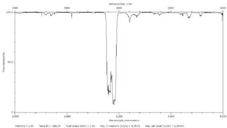
line
| Wavelength, micrometers | Transmittance (%) | | ---------------------- | ----------------- | | 2500 | 100.0 | | 2950 | 100.0 | | 3500 | 100.0 | | 3600 | 50.0 | | 3800 | 10.0 | | 4000 | 100.0 | | 4500 | 100.0 | | 5000 | 100.0 | | 5300 | 100.0 |Figure 38.7 Benzene (GH₆). Strong absorption around 3.2 - 3.3 μm, CL=5000 ppmxm, Source: PNNL
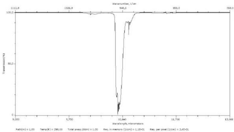
line
| Wavelength, micrometers | Transmittance (%) | | ----------------------- | ----------------- | | 9,000 | 1111.9 | | 9,750 | 1826.9 | | 10,840 | 946.0 | | 11,700 | 855.0 | | 13,000 | 769.0 |Figure 38.8 Sulfur hexafluoride (Sf). Strong absorption around 10.6 μm, CL=50 ppmxm, Source: PNNL
About FLIR Systems
FLIR Systems was established in 1978 to pioneer the development of high-performance infrared imaging systems, and is the world leader in the design, manufacture, and marketing of thermal imaging systems for a wide variety of commercial, industrial, and government applications. Today, FLIR Systems embraces five major companies with outstanding achievements in infrared technology since 1958—the Swedish AGEMA Infrared Systems (formerly AGA Infrared Systems), the three United States companies Indigo Systems, FSI, and Inframetrics, and the French company Cedip.
Since 2007, FLIR Systems has acquired several companies with world-leading expertise in sensor technologies:
• Extech Instruments (2007)
• Ifara Tecnologías (2008)
• Salvador Imaging (2009)
• OmniTech Partners (2009)
• Directed Perception (2009)
• Raymarine (2010)
• ICx Technologies (2010)
• TackTick Marine Digital Instruments (2011)
• Aerius Photonics (2011)
- Lorex Technology (2012)
- Traficon (2012)
• MARSS (2013)
• DigitalOptics micro-optics business (2013)
• DVTEL (2015)
- Point Grey Research (2016)
• Prox Dynamics (2016)
Figure 39.1 Patent documents from the early 1960s
FLIR Systems has three manufacturing plants in the United States (Portland, OR, Boston, MA, Santa Barbara, CA) and one in Sweden (Stockholm). Since 2007 there is also a
manufacturing plant in Tallinn, Estonia. Direct sales offices in Belgium, Brazil, China, France, Germany, Great Britain, Hong Kong, Italy, Japan, Korea, Sweden, and the USA—together with a worldwide network of agents and distributors—support our international customer base.
FLIR Systems is at the forefront of innovation in the infrared camera industry. We anticipate market demand by constantly improving our existing cameras and developing new ones. The company has set milestones in product design and development such as the introduction of the first battery-operated portable camera for industrial inspections, and the first uncooled infrared camera, to mention just two innovations.
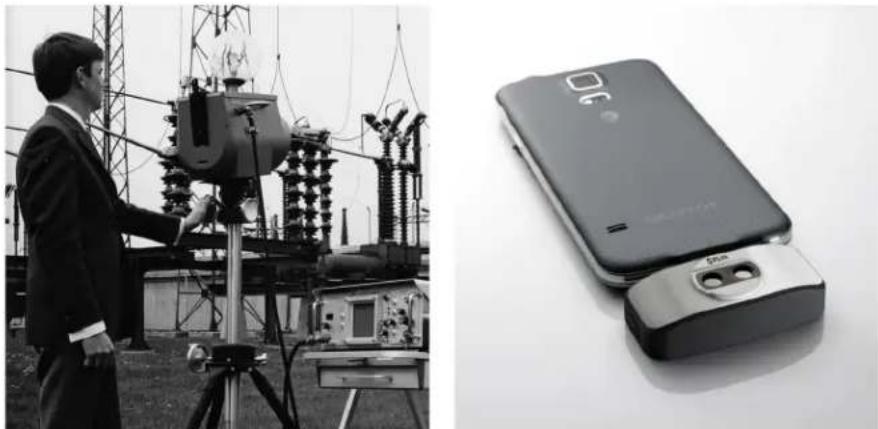
natural_image
Black-and-white photo showing a person operating a high-voltage power station with equipment, alongside a smartphone displaying the same device (no visible text or symbols)Figure 39.2 1969: Thermovision Model 661. The Figure 39.3 2015: FLIR One, an accessory to camera weighed approximately 25 kg (55 lb.), the iPhone and Android mobile phones. Weight: 90 g oscilloscope 20 kg (44 lb.), and the tripod 15 kg (3.2 oz.). (33 lb.). The operator also needed a 220 VAC generator set, and a 10 L (2.6 US gallon) jar with liquid nitrogen. To the left of the oscilloscope the Polaroid attachment (6 kg/13 lb.) can be seen.
FLIR Systems manufactures all vital mechanical and electronic components of the camera systems itself. From detector design and manufacturing, to lenses and system electronics, to final testing and calibration, all production steps are carried out and supervised by our own engineers. The in-depth expertise of these infrared specialists ensures the accuracy and reliability of all vital components that are assembled into your infrared camera.
39.1 More than just an infrared camera
At FLIR Systems we recognize that our job is to go beyond just producing the best infrared camera systems. We are committed to enabling all users of our infrared camera systems to work more productively by providing them with the most powerful camera-software combination. Especially tailored software for predictive maintenance, R & D, and process monitoring is developed in-house. Most software is available in a wide variety of languages.
We support all our infrared cameras with a wide variety of accessories to adapt your equipment to the most demanding infrared applications.
39.2 Sharing our knowledge
Although our cameras are designed to be very user-friendly, there is a lot more to thermography than just knowing how to handle a camera. Therefore, FLIR Systems has founded the Infrared Training Center (ITC), a separate business unit, that provides certified training courses. Attending one of the ITC courses will give you a truly hands-on learning experience.
The staff of the ITC are also there to provide you with any application support you may need in putting infrared theory into practice.
39.3 Supporting our customers
FLIR Systems operates a worldwide service network to keep your camera running at all times. If you discover a problem with your camera, local service centers have all the equipment and expertise to solve it within the shortest possible time. Therefore, there is no need to send your camera to the other side of the world or to talk to someone who does not speak your language.
Terms, laws, and definitions
| Term Definition | |
| Absorption and emission | The capacity or ability of an object to absorb incident radiated energy is always the same as the capacity to emit its own energy as radiation |
| Apparent temperature uncompensated | reading from an infrared instrument, containing all radiation incident on the instrument, regardless of its sources2 |
| Color palette assigns different colors to | indicate specific levels of apparent temperature. Palettes can provide high or low contrast, depending on the colors used in them |
| Conduction direct transfer of thermal energy | energy from molecule to molecule, caused by collisions between the molecules |
| Convection heat transfer mode where a fluid is brought into motion, either by gravity or another force, thereby transferring heat from one place to another | |
| Diagnostics examination of symptoms and syndromes to determine the nature of faults or failures | |
| Direction of heat transfer | Heat will spontaneously flow from hotter to colder, thereby transferring thermal energy from one place to another |
| Emissivity ratio of the power radiated by real bodies to the power that is radiated by a blackbody at the same temperature and at the same wavelength | |
| Energy conservation7 | The sum of the total energy contents in a closed system is constant |
| Exitant radiation radiation that leaves the surface of an object, regardless of its original sources | |
| Heat thermal energy that is transferred | between two objects (systems) due to their difference in temperature |
| Heat transfer rate | The heat transfer rate under steady state conditions is directly proportional to the thermal conductivity of the object, the cross-sectional area of the object through which the heat flows, and the temperature difference between the two ends of the object. It is inversely proportional to the length, or thickness, of the object |
| Incident radiation | radiation that strikes an object from its surroundings |
| IR thermography | process of acquisition and analysis of thermal information from non-contact thermal imaging devices |
| Isotherm | replaces certain colors in the scale with a contrasting color. It marks an interval of equal apparent temperature |
| Qualitative thermography thermography | that relies on the analysis of thermal patterns to reveal the existence of and to locate the position of anomalies11 |
| Quantitative thermography | thermography that uses temperature measurement to determine the seriousness of an anomaly, in order to establish pair priorities1 |
| Radiative heat transfer Heat transfer by | the emission and absorption of thermal radiation |
| Reflected apparent temperature apparent | temperature of the environment that is reflected by the target into the IR caméra |
| Spatial resolution ability of an IR camera | to resolve small objects or details |
| Temperature measure of the average k | kinetic energy of the molecules and atoms that make up the substance |
| Thermal energy total kinetic energy of | the molecules that make up the object 13 |
| Thermal gradient gradual change in tem | perature over distance 12 |
| Thermal tuning process of putting the | colors of the image on the object of analysis, in order to maximize contrast |
Thermographic measurement techniques
41.1 Introduction
An infrared camera measures and images the emitted infrared radiation from an object. The fact that radiation is a function of object surface temperature makes it possible for the camera to calculate and display this temperature.
However, the radiation measured by the camera does not only depend on the temperature of the object but is also a function of the emissivity. Radiation also originates from the surroundings and is reflected in the object. The radiation from the object and the reflected radiation will also be influenced by the absorption of the atmosphere.
To measure temperature accurately, it is therefore necessary to compensate for the effects of a number of different radiation sources. This is done on-line automatically by the camera. The following object parameters must, however, be supplied for the camera:
• The emissivity of the object
• The reflected apparent temperature
- The distance between the object and the camera
• The relative humidity
• Temperature of the atmosphere
41.2 Emissivity
The most important object parameter to set correctly is the emissivity which, in short, is a measure of how much radiation is emitted from the object, compared to that from a perfect blackbody of the same temperature.
Normally, object materials and surface treatments exhibit emissivity ranging from approximately 0.1 to 0.95. A highly polished (mirror) surface falls below 0.1, while an oxidized or painted surface has a higher emissivity. Oil-based paint, regardless of color in the visible spectrum, has an emissivity over 0.9 in the infrared. Human skin exhibits an emissivity 0.97 to 0.98.
Non-oxidized metals represent an extreme case of perfect opacity and high reflexivity, which does not vary greatly with wavelength. Consequently, the emissivity of metals is low – only increasing with temperature. For non-metals, emissivity tends to be high, and decreases with temperature.
41.2.1 Finding the emissivity of a sample
41.2.1.1 Step 1: Determining reflected apparent temperature
Use one of the following two methods to determine reflected apparent temperature:
41.2.1.1.1 Method 1: Direct method
Follow this procedure:
- Look for possible reflection sources, considering that the incident angle = reflection angle (a = b).
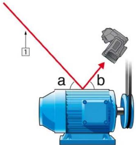
Figure 41.1 1 = Reflection source
- If the reflection source is a spot source, modify the source by obstructing it using a piece if cardboard.
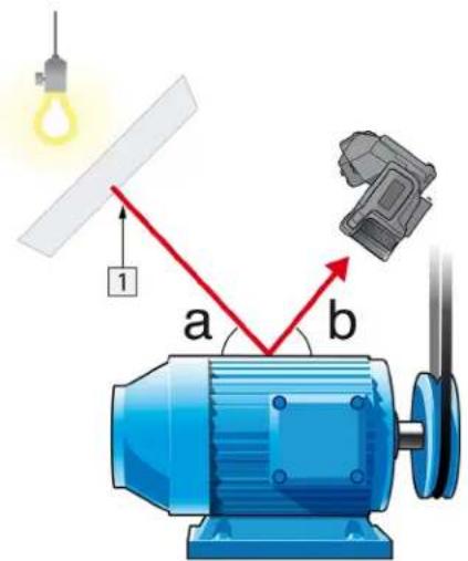
Figure 41.2 1 = Reflection source
-
Measure the radiation intensity (= apparent temperature) from the reflection source using the following settings:
-
Emissivity: 1.0
- D_obj : 0
You can measure the radiation intensity using one of the following two methods:
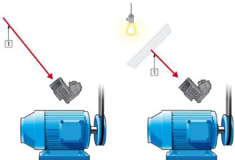
Figure 41.3 1 = Reflection source
Figure 41.4 1 = Reflection source
You can not use a thermocouple to measure reflected apparent temperature, because a thermocouple measures temperature, but apparent temperature is radiation intensity.
41.2.1.1.2 Method 2: Reflector method
Follow this procedure:
- Crumble up a large piece of aluminum foil.
- Uncrumble the aluminum foil and attach it to a piece of cardboard of the same size.
- Put the piece of cardboard in front of the object you want to measure. Make sure that the side with aluminum foil points to the camera.
-
Set the emissivity to 1.0.
-
Measure the apparent temperature of the aluminum foil and write it down. The foil is considered a perfect reflector, so its apparent temperature equals the reflected apparent temperature from the surroundings.
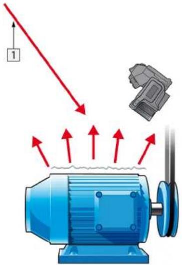
Figure 41.5 Measuring the apparent temperature of the aluminum foil.
41.2.1.2 Step 2: Determining the emissivity
Follow this procedure:
- Select a place to put the sample.
- Determine and set reflected apparent temperature according to the previous procedure.
- Put a piece of electrical tape with known high emissivity on the sample.
- Heat the sample at least 20 K above room temperature. Heating must be reasonably even.
- Focus and auto-adjust the camera, and freeze the image.
- Adjust Level and Span for best image brightness and contrast.
- Set emissivity to that of the tape (usually 0.97).
- Measure the temperature of the tape using one of the following measurement functions:
- Isotherm (helps you to determine both the temperature and how evenly you have heated the sample)
- Spot (simpler)
-
Box Avg (good for surfaces with varying emissivity).
-
Write down the temperature.
-
Move your measurement function to the sample surface.
- Change the emissivity setting until you read the same temperature as your previous measurement.
- Write down the emissivity.
Note
- Avoid forced convection
- Look for a thermally stable surrounding that will not generate spot reflections
- Use high quality tape that you know is not transparent, and has a high emissivity you are certain of
- This method assumes that the temperature of your tape and the sample surface are the same. If they are not, your emissivity measurement will be wrong.
41.3 Reflected apparent temperature
This parameter is used to compensate for the radiation reflected in the object. If the emissivity is low and the object temperature relatively far from that of the reflected it will be important to set and compensate for the reflected apparent temperature correctly.
41.4 Distance
The distance is the distance between the object and the front lens of the camera. This parameter is used to compensate for the following two facts:
- That radiation from the target is absorbed by the atmosphere between the object and the camera.
- That radiation from the atmosphere itself is detected by the camera.
41.5 Relative humidity
The camera can also compensate for the fact that the transmittance is also dependent on the relative humidity of the atmosphere. To do this set the relative humidity to the correct value. For short distances and normal humidity the relative humidity can normally be left at a default value of 50%.
41.6 Other parameters
In addition, some cameras and analysis programs from FLIR Systems allow you to compensate for the following parameters:
- Atmospheric temperature – i.e. the temperature of the atmosphere between the camera and the target
- External optics temperature – i.e. the temperature of any external lenses or windows used in front of the camera
- External optics transmittance – i.e. the transmission of any external lenses or windows used in front of the camera
42.1 Introduction
Calibration of a thermal camera is a prerequisite for temperature measurement. The calibration provides the relationship between the input signal and the physical quantity that the user wants to measure. However, despite its widespread and frequent use, the term "calibration" is often misunderstood and misused. Local and national differences as well as translation-related issues create additional confusion.
Unclear terminology can lead to difficulties in communication and erroneous translations, and subsequently to incorrect measurements due to misunderstandings and, in the worst case, even to lawsuits.
42.2 Definition—what is calibration?
The International Bureau of Weights and Measures defines calibration ^15 in the following way:
an operation that, under specified conditions, in a first step, establishes a relation between the quantity values with measurement uncertainties provided by measurement standards and corresponding indications with associated measurement uncertainties and, in a second step, uses this information to establish a relation for obtaining a measurement result from an indication.
The calibration itself may be expressed in different formats: this can be a statement, calibration function, calibration diagram, calibration curve ^7 , or calibration table.
Often, the first step alone in the above definition is perceived and referred to as being "calibration." However, this is not (always) sufficient.
Considering the calibration procedure of a thermal camera, the first step establishes the relation between emitted radiation (the quantity value) and the electrical output signal (the indication). This first step of the calibration procedure consists of obtaining a homogeneous (or uniform) response when the camera is placed in front of an extended source of radiation.
As we know the temperature of the reference source emitting the radiation, in the second step the obtained output signal (the indication) can be related to the reference source's temperature (measurement result). The second step includes drift measurement and compensation.
To be correct, calibration of a thermal camera is, strictly, not expressed through temperature. Thermal cameras are sensitive to infrared radiation: therefore, at first you obtain a radiance correspondence, then a relationship between radiance and temperature. For bolometer cameras used by non-R&D customers, radiance is not expressed: only the temperature is provided.
42.3 Camera calibration at FLIR Systems
Without calibration, an infrared camera would not be able to measure either radiance or temperature. At FLIR Systems, the calibration of uncooled microbolometer cameras with a
measurement capability is carried out during both production and service. Cooled cameras with photon detectors are often calibrated by the user with special software. With this type of software, in theory, common handheld uncooled thermal cameras could be calibrated by the user too. However, as this software is not suitable for reporting purposes, most users do not have it. Non-measuring devices that are used for imaging only do not need temperature calibration. Sometimes this is also reflected in camera terminology when talking about infrared or thermal imaging cameras compared with thermography cameras, where the latter are the measuring devices.
The calibration information, no matter if the calibration is done by FLIR Systems or the user, is stored in calibration curves, which are expressed by mathematical functions. As radiation intensity changes with both temperature and the distance between the object and the camera, different curves are generated for different temperature ranges and exchangeable lenses.
42.4 The differences between a calibration performed by a user and that performed directly at FLIR Systems
First, the reference sources that FLIR Systems uses are themselves calibrated and traceable. This means, at each FLIR Systems site performing calibration, that the sources are controlled by an independent national authority. The camera calibration certificate is confirmation of this. It is proof that not only has the calibration been performed by FLIR Systems but that it has also been carried out using calibrated references. Some users own or have access to accredited reference sources, but they are very few in number.
Second, there is a technical difference. When performing a user calibration, the result is often (but not always) not drift compensated. This means that the values do not take into account a possible change in the camera's output when the camera's internal temperature varies. This yields a larger uncertainty. Drift compensation uses data obtained in climate-controlled chambers. All FLIR Systems cameras are drift compensated when they are first delivered to the customer and when they are recalibrated by FLIR Systems service departments.
42.5 Calibration, verification and adjustment
A common misconception is to confuse calibration with verification or adjustment. Indeed, calibration is a prerequisite for verification, which provides confirmation that specified requirements are met. Verification provides objective evidence that a given item fulfills specified requirements. To obtain the verification, defined temperatures (emitted radiation) of calibrated and traceable reference sources are measured. The measurement results, including the deviation, are noted in a table. The verification certificate states that these measurement results meet specified requirements. Sometimes, companies or organizations offer and market this verification certificate as a “calibration certificate.”
Proper verification—and by extension calibration and/or recalibration—can only be achieved when a validated protocol is respected. The process is more than placing the camera in front of blackbodies and checking if the camera output (as temperature, for instance) corresponds to the original calibration table. It is often forgotten that a camera is not sensitive to temperature but to radiation. Furthermore, a camera is an imaging system, not just a single sensor. Consequently, if the optical configuration allowing the camera to "collect" radiance is poor or misaligned, then the "verification" (or calibration or recalibration) is worthless.
For instance, one has to ensure that the distance between the blackbody and the camera as well as the diameter of the blackbody cavity are chosen so as to reduce stray radiation and the size-of-source effect.
To summarize: a validated protocol must comply with the physical laws for radiance, and not only those for temperature.
Calibration is also a prerequisite for adjustment, which is the set of operations carried out on a measuring system such that the system provides prescribed indications corresponding to given values of quantities to be measured, typically obtained from measurement standards. Simplified, adjustment is a manipulation that results in instruments that measure correctly within their specifications. In everyday language, the term “calibration” is widely used instead of “adjustment” for measuring devices.
42.6 Non-uniformity correction
When the thermal camera displays "Calibrating..." it is adjusting for the deviation in response of each individual detector element (pixel). In thermography, this is called a "non-uniformity correction" (NUC). It is an offset update, and the gain remains unchanged.
The European standard EN 16714-3, Non-destructive Testing—Thermographic Testing—Part 3: Terms and Definitions, defines an NUC as “Image correction carried out by the camera software to compensate for different sensitivities of detector elements and other optical and geometrical disturbances.”
During the NUC (the offset update), a shutter (internal flag) is placed in the optical path, and all the detector elements are exposed to the same amount of radiation originating from the shutter. Therefore, in an ideal situation, they should all give the same output signal. However, each individual element has its own response, so the output is not uniform. This deviation from the ideal result is calculated and used to mathematically perform an image correction, which is essentially a correction of the displayed radiation signal. Some cameras do not have an internal flag. In this case, the offset update must be performed manually using special software and an external uniform source of radiation.
An NUC is performed, for example, at start-up, when changing a measurement range, or when the environment temperature changes. Some cameras also allow the user to trigger it manually. This is useful when you have to perform a critical measurement with as little image disturbance as possible.
42.7 Thermal image adjustment (thermal tuning)
Some people use the term “image calibration” when adjusting the thermal contrast and brightness in the image to enhance specific details. During this operation, the temperature interval is set in such a way that all available colors are used to show only (or mainly) the temperatures in the region of interest. The correct term for this manipulation is “thermal image adjustment” or “thermal tuning”, or, in some languages, “thermal image optimization.” You must be in manual mode to undertake this, otherwise the camera will set the lower and upper limits of the displayed temperature interval automatically to the coldest and hottest temperatures in the scene.
History of infrared technology
Before the year 1800, the existence of the infrared portion of the electromagnetic spectrum wasn't even suspected. The original significance of the infrared spectrum, or simply 'the infrared' as it is often called, as a form of heat radiation is perhaps less obvious today than was at the time of its discovery by Herschel in 1800.
natural_image
Portrait of a man with long hair and a crescent moon in the sky (no text or symbols visible)Figure 43.1 Sir William Herschel (1738–1822)
The discovery was made accidentally during the search for a new optical material. Sir William Herschel – Royal Astronomer to King George III of England, and already famous for his discovery of the planet Uranus – was searching for an optical filter material to reduce the brightness of the sun's image in telescopes during solar observations. While testing different samples of colored glass which gave similar reductions in brightness he was intrigued to find that some of the samples passed very little of the sun's heat, while others passed so much heat that he risked eye damage after only a few seconds' observation.
Herschel was soon convinced of the necessity of setting up a systematic experiment, with the objective of finding a single material that would give the desired reduction in brightness as well as the maximum reduction in heat. He began the experiment by actually repeating Newton's prism experiment, but looking for the heating effect rather than the visual distribution of intensity in the spectrum. He first blackened the bulb of a sensitive mercury-in-glass thermometer with ink, and with this as his radiation detector he proceeded to test the heating effect of the various colors of the spectrum formed on the top of a table by passing sunlight through a glass prism. Other thermometers, placed outside the sun's rays, served as controls.
As the blackened thermometer was moved slowly along the colors of the spectrum, the temperature readings showed a steady increase from the violet end to the red end. This was not entirely unexpected, since the Italian researcher, Landriani, in a similar experiment in 1777 had observed much the same effect. It was Herschel, however, who was the first to recognize that there must be a point where the heating effect reaches a maximum, and that measurements confined to the visible portion of the spectrum failed to locate this point.
natural_image
Portrait engraving of a man with curly hair and formal attire (no text or symbols visible)Figure 43.2 Marsilio Landriani (1746–1815)
Moving the thermometer into the dark region beyond the red end of the spectrum, Herschel confirmed that the heating continued to increase. The maximum point, when he found it, lay well beyond the red end – in what is known today as the 'infrared wavelength:
When Herschel revealed his discovery, he referred to this new portion of the electromagnetic spectrum as the 'thermometrical spectrum'. The radiation itself he sometimes referred to as 'dark heat', or simply 'the invisible rays'. Ironically, and contrary to popular opinion, it wasn't Herschel who originated the term 'infrared'. The word only began to appear in print around 75 years later, and it is still unclear who should receive credit as the originator.
Herschel's use of glass in the prism of his original experiment led to some early controversies with his contemporaries about the actual existence of the infrared wavelengths. Different investigators, in attempting to confirm his work, used various types of glass indiscriminately, having different transparencies in the infrared. Through his later experiments, Herschel was aware of the limited transparency of glass to the newly-discovered thermal radiation, and he was forced to conclude that optics for the infrared would probably be doomed to the use of reflective elements exclusively (i.e. plane and curved mirrors). Fortunately, this proved to be true only until 1830, when the Italian investigator, Melloni, made his great discovery that naturally occurring rock salt (NaCl) – which was available in large enough natural crystals to be made into lenses and prisms – is remarkably transparent to the infrared. The result was that rock salt became the principal infrared optical material, and remained so for the next hundred years, until the art of synthetic crystal growing was mastered in the 1930's.
natural_image
Portrait painting of a man in 19th-century attire seated at a scientific apparatus (no visible text or symbols)Figure 43.3 Macedonio Melloni (1798–1854)
Thermometers, as radiation detectors, remained unchallenged until 1829, the year Nobili invented the thermocouple. (Herschel's own thermometer could be read to 0.2 °C (0.036 °F), and later models were able to be read to 0.05 °C (0.09 °F)). Then a breakthrough occurred; Melloni connected a number of thermocouples in series to form the first thermopile. The new device was at least 40 times as sensitive as the best thermometer of the day for detecting heat radiation – capable of detecting the heat from a person standing three meters away.
The first so-called 'heat-picture' became possible in 1840, the result of work by Sir John Herschel, son of the discoverer of the infrared and a famous astronomer in his own right. Based upon the differential evaporation of a thin film of oil when exposed to a heat pattern focused upon it, the thermal image could be seen by reflected light where the interference effects of the oil film made the image visible to the eye. Sir John also managed to obtain primitive record of the thermal image on paper, which he called a 'thermograph'.
natural_image
Portrait of an elderly man with a beard, wearing formal attire (no visible text or symbols)Figure 43.4 Samuel P. Langley (1834–1906)
The improvement of infrared-detector sensitivity progressed slowly. Another major break-through, made by Langley in 1880, was the invention of the bolometer. This consisted of a thin blackened strip of platinum connected in one arm of a Wheatstone bridge circuit upon which the infrared radiation was focused and to which a sensitive galvanometer responded. This instrument is said to have been able to detect the heat from a cow at a distance of 400 meters.
An English scientist, Sir James Dewar, first introduced the use of liquefied gases as cooling agents (such as liquid nitrogen with a temperature of -196 °C (-320.8 °F)) in low temperature research. In 1892 he invented a unique vacuum insulating container in which it is possible to store liquefied gases for entire days. The common 'thermos bottle', used for storing hot and cold drinks, is based upon his invention.
Between the years 1900 and 1920, the inventors of the world ‘discovered’ the infrared. Many patents were issued for devices to detect personnel, artillery, aircraft, ships – and even icebergs. The first operating systems, in the modern sense, began to be developed during the 1914–18 war, when both sides had research programs devoted to the military exploitation of the infrared. These programs included experimental systems for enemy intrusion/detection, remote temperature sensing, secure communications, and ‘flying torpedo’ guidance. An infrared search system tested during this period was able to detect an approaching airplane at a distance of 1.5 km (0.94 miles), or a person more than 300 meters (984 ft.) away.
The most sensitive systems up to this time were all based upon variations of the bolometer idea, but the period between the two wars saw the development of two revolutionary new infrared detectors: the image converter and the photon detector. At first, the image converter received the greatest attention by the military, because it enabled an observer for the first time in history to literally 'see in the dark'. However, the sensitivity of the image converter was limited to the near infrared wavelengths, and the most interesting military targets (i.e. enemy soldiers) had to be illuminated by infrared search beams. Since this involved the risk of giving away the observer's position to a similarly-equipped enemy observer, it is understandable that military interest in the image converter eventually faded.
The tactical military disadvantages of so-called 'active' (i.e. search beam-equipped) thermal imaging systems provided impetus following the 1939–45 war for extensive secret military infrared-research programs into the possibilities of developing 'passive' (no search beam) systems around the extremely sensitive photon detector. During this period, military secrecy regulations completely prevented disclosure of the status of infrared-imaging technology. This secrecy only began to be lifted in the middle of the 1950's, and from that time adequate thermal-imaging devices finally began to be available to civilian science and industry.
Theory of thermography
44.1 Introduction
The subjects of infrared radiation and the related technique of thermography are still new to many who will use an infrared camera. In this section the theory behind thermography will be given.
44.2 The electromagnetic spectrum
The electromagnetic spectrum is divided arbitrarily into a number of wavelength regions, called bands, distinguished by the methods used to produce and detect the radiation. There is no fundamental difference between radiation in the different bands of the electromagnetic spectrum. They are all governed by the same laws and the only differences are those due to differences in wavelength.
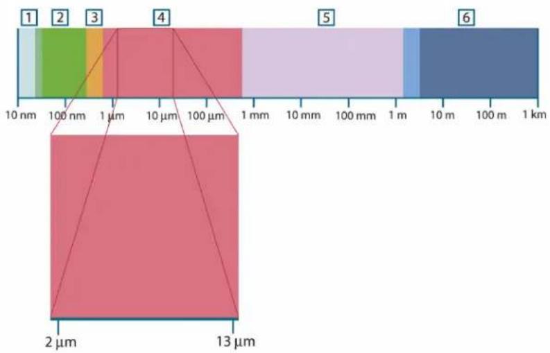
other
| Segment | Value | |---|---| | 1 | 10 nm | | 2 | 100 nm | | 3 | 1 μm | | 4 | 10 μm | | 5 | 100 μm | | 6 | 1 km | | 7 | 10 m | | 8 | 100 m | | 9 | 1 km | | 10 | 1 km | | 11 | 2 μm | | 12 | 13 μm |Figure 44.1 The electromagnetic spectrum. 1: X-ray; 2: UV; 3: Visible; 4: IR; 5: Microwaves; 6: Radiowaves.
Thermography makes use of the infrared spectral band. At the short-wavelength end the boundary lies at the limit of visual perception, in the deep red. At the long-wavelength end it merges with the microwave radio wavelengths, in the millimeter range.
The infrared band is often further subdivided into four smaller bands, the boundaries of which are also arbitrarily chosen. They include: the near infrared (0.75–3 m), the middle infrared (3–6 m), the far infrared (6–15 m) and the extreme infrared (15–100 m). Although the wavelengths are given in m (micrometers), other units are often still used to measure wavelength in this spectral region, e.g. nanometer (nm) and Ångström (Å).
The relationships between the different wavelength measurements is:
$$ 1 0 0 0 0 \mathrm{A} = 1 0 0 0 \mathrm{nm} = 1 \mu = 1 \mu \mathrm{m} $$
44.3 Blackbody radiation
A blackbody is defined as an object which absorbs all radiation that impinges on it at any wavelength. The apparent misnomer black relating to an object emitting radiation is explained by Kirchhoff's Law (after Gustav Robert Kirchhoff, 1824–1887), which states that a body capable of absorbing all radiation at any wavelength is equally capable in the emission of radiation.
natural_image
Portrait of a bearded man in formal 19th-century attire (no text or symbols visible)Figure 44.2 Gustav Robert Kirchhoff (1824–1887)
The construction of a blackbody source is, in principle, very simple. The radiation characteristics of an aperture in an isotherm cavity made of an opaque absorbing material represents almost exactly the properties of a blackbody. A practical application of the principle to the construction of a perfect absorber of radiation consists of a box that is light tight except for an aperture in one of the sides. Any radiation which then enters the hole is scattered and absorbed by repeated reflections so only an infinitesimal fraction can possibly escape. The blackness which is obtained at the aperture is nearly equal to a blackbody and almost perfect for all wavelengths.
By providing such an isothermal cavity with a suitable heater it becomes what is termed a cavity radiator. An isothermal cavity heated to a uniform temperature generates blackbody radiation, the characteristics of which are determined solely by the temperature of the cavity. Such cavity radiators are commonly used as sources of radiation in temperature reference standards in the laboratory for calibrating thermographic instruments, such as a FLIR Systems camera for example.
If the temperature of blackbody radiation increases to more than 525^ C ( 977^ F), the source begins to be visible so that it appears to the eye no longer black. This is the incipient red heat temperature of the radiator, which then becomes orange or yellow as the temperature increases further. In fact, the definition of the so-called color temperature of an object is the temperature to which a blackbody would have to be heated to have the same appearance.
Now consider three expressions that describe the radiation emitted from a blackbody.
44.3.1 Planck's law
natural_image
Portrait of a man in formal 19th-century attire, no visible text or symbolsFigure 44.3 Max Planck (1858–1947)
Max Planck (1858–1947) was able to describe the spectral distribution of the radiation from a blackbody by means of the following formula:
$$ W _ {\lambda b} = \frac {2 \pi h c ^ {2}}{\lambda^ {5} \left(e ^ {h c / \lambda k T} - 1\right)} \times 1 0 ^ {- 6} [ W a t t / m ^ {2}, \mu m ] $$
where:
| W_AB | Blackbody spectral radiant emittance at wavelength . |
| c | Velocity of light = 3 × ^8 10/s |
| h Planck's constant = 6.6 × 10 | ^-34 Joule sec. |
| k Boltzmann's constant = 1.4 × | 10 ^-23 Joule/K. |
| T Absolute temperature (K) of a | blackbody. |
| Wavelength ( m). |
Note The factor 10^-6 is used since spectral emittance in the curves is expressed in Watt/m ^2 , m.
Planck's formula, when plotted graphically for various temperatures, produces a family of curves. Following any particular Planck curve, the spectral emittance is zero at = 0 , then increases rapidly to a maximum at a wavelength and after passing it approaches zero again at very long wavelengths. The higher the temperature, the shorter the wavelength at which maximum occurs.
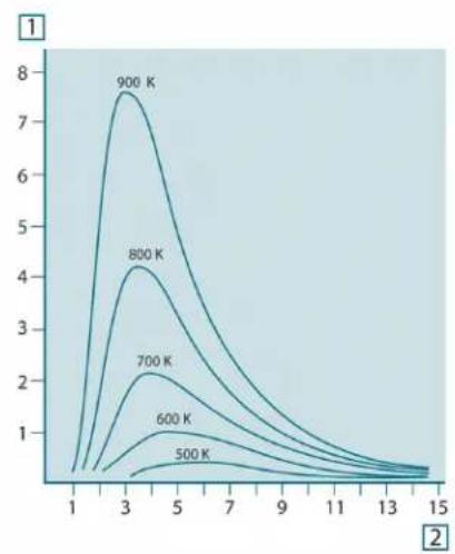
line
| Temperature | Peak Value | | ----------- | ---------- | | 900 K | ~7.5 | | 800 K | ~4.2 | | 700 K | ~2.1 | | 600 K | ~1.2 | | 500 K | ~0.8 |Figure 44.4 Blackbody spectral radiant emittance according to Planck's law, plotted for various absolute temperatures. 1: Spectral radiant emittance (W/6m 10^3( m) ); 2: Wavelength ( m )
44.3.2 Wien's displacement law
By differentiating Planck's formula with respect to , and finding the maximum, we have:
$$ \lambda_ {\max} = \frac {2 8 9 8}{T} [ \mu m ] $$
This is Wien's formula (after Wilhelm Wien, 1864–1928), which expresses mathematically the common observation that colors vary from red to orange or yellow as the temperature of a thermal radiator increases. The wavelength of the color is the same as the wavelength calculated for _max . A good approximation of the value _ex for a given blackbody temperature is obtained by applying the rule-of-thumb 3 000/T m. Thus, a very hot star such as Sirius (11 000 K), emitting bluish-white light, radiates with the peak of spectral radiant emittance occurring within the invisible ultraviolet spectrum, at wavelength 0.27 m.
natural_image
Portrait of a man in formal attire with mustache (no visible text or symbols)Figure 44.5 Wilhelm Wien (1864–1928)
The sun (approx. 6 000 K) emits yellow light, peaking at about 0.5 m in the middle of the visible light spectrum.
At room temperature (300 K) the peak of radiant emittance lies at 9.7 μm, in the far infrared, while at the temperature of liquid nitrogen (77 K) the maximum of the almost insignificant amount of radiant emittance occurs at 38 μm, in the extreme infrared wavelengths.
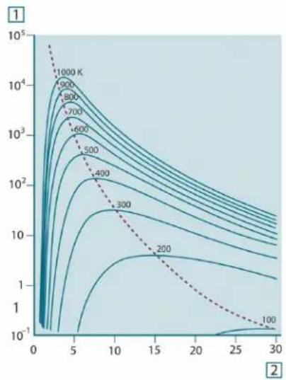
line
| Temperature (K) | Value | | --------------- | ----- | | 1000 | 10^4 | | 800 | 10^3 | | 700 | 10^2 | | 600 | 10^1 | | 500 | 10^0 | | 400 | 10^-1 | | 300 | 10^-2 | | 200 | 10^-3 | | 100 | 10^-4 |Figure 44.6 Planckian curves plotted on semi-log scales from 100 K to 1000 K. The dotted line represents the locus of maximum radiant emittance at each temperature as described by Wien's displacement law. 1: Spectral radiant emittance (W/c ( m) ); 2: Wavelength ( m ).
44.3.3 Stefan-Boltzmann's law
By integrating Planck's formula from = 0 to = , we obtain the total radiant emittance (W_b) of a blackbody:
$$ W _ {b} = \sigma T ^ {4} [ \mathrm{Watt/m} ^ {2} ] $$
This is the Stefan-Boltzmann formula (after Josef Stefan, 1835–1893, and Ludwig Boltzmann, 1844–1906), which states that the total emissive power of a blackbody is proportional to the fourth power of its absolute temperature. Graphically represents the area below the Planck curve for a particular temperature. It can be shown that the radiant emittance in the interval = 0 has only 25% of the total, which represents about the amount of the sun's radiation which lies inside the visible light spectrum.
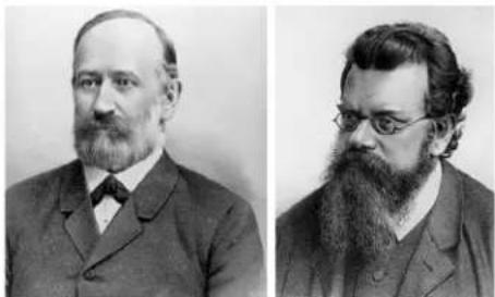
natural_image
Black-and-white portrait of two men in formal attire, one with a beard and the other with glasses (no text or symbols visible)Figure 44.7 Josef Stefan (1835–1893), and Ludwig Boltzmann (1844–1906)
Using the Stefan-Boltzmann formula to calculate the power radiated by the human body, at a temperature of 300 K and an external surface area of approx. we obtain 1 kW. This power loss could not be sustained if it were not for the compensating absorption of radiation from surrounding surfaces, at room temperatures which do not vary too drastically from the temperature of the body – or, of course, the addition of clothing.
44.3.4 Non-blackbody emitters
So far, only blackbody radiators and blackbody radiation have been discussed. However, real objects almost never comply with these laws over an extended wavelength region – although they may approach the blackbody behavior in certain spectral intervals. For example, a certain type of white paint may appear perfectly white in the visible light spectrum but becomes distinctly gray at about 2 m, and beyond 3 m it is almost black.
There are three processes which can occur that prevent a real object from acting like a blackbody: a fraction of the incident radiation may be absorbed, a fraction may be reflected, and a fraction may be transmitted. Since all of these factors are more or less wavelength dependent, the subscript is used to imply the spectral dependence of their definitions. Thus:
- The spectral absorptance = the ratio of the spectral radiant power absorbed by an object to that incident upon it.
- The spectral reflectance = the ratio of the spectral radiant power reflected by an object to that incident upon it.
- The spectral transmittance = the ratio of the spectral radiant power transmitted through an object to that incident upon it.
The sum of these three factors must always add up to the whole at any wavelength, so we have the relation:
$$ \alpha_ {\lambda} + \rho_ {\lambda} + \tau_ {\lambda} = 1 $$
For opaque materials t = 0 and the relation simplifies to:
$$ \varepsilon_ {\lambda} + \rho_ {\lambda} = 1 $$
Another factor, called the emissivity, is required to describe the fraction of the radiant emittance of a blackbody produced by an object at a specific temperature. Thus, we have the definition:
The spectral emissivity _e the ratio of the spectral radiant power from an object to that from a blackbody at the same temperature and wavelength.
Expressed mathematically, this can be written as the ratio of the spectral emittance of the object to that of a blackbody as follows:
$$ \varepsilon_ {\lambda} = \frac {W _ {\lambda o}}{W _ {\lambda b}} $$
Generally speaking, there are three types of radiation source, distinguished by the ways in which the spectral emittance of each varies with wavelength.
- A blackbody, for which = = 1
- A graybody, for which = = constant less than 1
- A selective radiator, for which varies with wavelength
According to Kirchhoff's law, for any material the spectral emissivity and spectral absorptance of a body are equal at any specified temperature and wavelength. That is:
$$ \varepsilon_ {\lambda} = \alpha_ {\lambda} $$
From this we obtain, for an opaque material (since = 1 ):
$$ \varepsilon_ {\lambda} + \rho_ {\lambda} = 1 $$
For highly polished materials approaches zero, so that for a perfectly reflecting material (i.e. a perfect mirror) we have:
$$ \rho_ {\lambda} = 1 $$
For a graybody radiator, the Stefan-Boltzmann formula becomes:
$$ W = \varepsilon \sigma T ^ {4} [ \mathrm{Watt/m} ^ {2} ] $$
This states that the total emissive power of a graybody is the same as a blackbody at the same temperature reduced in proportion to the value of from the graybody.
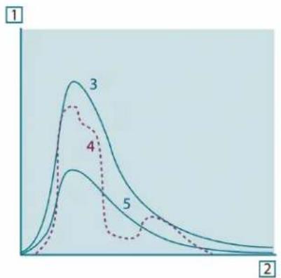
line
| Curve | Peak Position | Value | |-------|---------------|-------| | 3 | First Peak | High | | 4 | Second Peak | Medium| | 5 | Third Peak | Low |Figure 44.8 Spectral radiant emittance of three types of radiators. 1: Spectral radiant emittance; 2: Wavelength; 3: Blackbody; 4: Selective radiator; 5: Graybody.
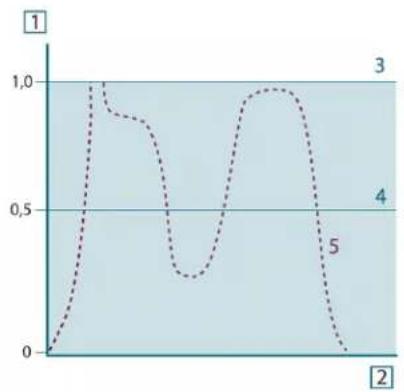
line
| x | y | | ---- | ----- | | 0 | 0.0 | | 1 | 1.0 | | 2 | 0.5 | | 3 | 1.0 | | 4 | 0.5 | | 5 | 0.0 |Figure 44.9 Spectral emissivity of three types of radiators. 1: Spectral emissivity; 2: Wavelength; 3: Blackbody; 4: Graybody; 5: Selective radiator.
44.4 Infrared semi-transparent materials
Consider now a non-metallic, semi-transparent body – let us say, in the form of a thick flat plate of plastic material. When the plate is heated, radiation generated within its volume must work its way toward the surfaces through the material in which it is partially absorbed. Moreover, when it arrives at the surface, some of it is reflected back into the interior. The back-reflected radiation is again partially absorbed, but some of it arrives at the other surface, through which most of it escapes; part of it is reflected back again. Although the progressive reflections become weaker and weaker they must all be added up when the total emittance of the plate is sought. When the resulting geometrical series is summed, the effective emissivity of a semi-transparent plate is obtained as:
$$ \varepsilon_ {\lambda} = \frac {(1 - \rho_ {\lambda}) (1 - \tau_ {\lambda})}{1 - \rho_ {\lambda} \tau_ {\lambda}} $$
When the plate becomes opaque this formula is reduced to the single formula:
$$ \varepsilon_ {\lambda} = 1 - \rho_ {\lambda} $$
This last relation is a particularly convenient one, because it is often easier to measure reflectance than to measure emissivity directly.
The measurement formula
As already mentioned, when viewing an object, the camera receives radiation not only from the object itself. It also collects radiation from the surroundings reflected via the object surface. Both these radiation contributions become attenuated to some extent by the atmosphere in the measurement path. To this comes a third radiation contribution from the atmosphere itself.
This description of the measurement situation, as illustrated in the figure below, is so far a fairly true description of the real conditions. What has been neglected could for instance be sun light scattering in the atmosphere or stray radiation from intense radiation sources outside the field of view. Such disturbances are difficult to quantify, however, in most cases they are fortunately small enough to be neglected. In case they are not negligible, the measurement configuration is likely to be such that the risk for disturbance is obvious, at least to a trained operator. It is then his responsibility to modify the measurement situation to avoid the disturbance e.g. by changing the viewing direction, shielding off intense radiation sources etc.
Accepting the description above, we can use the figure below to derive a formula for the calculation of the object temperature from the calibrated camera output.
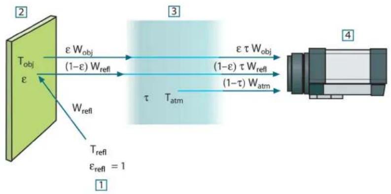
flowchart
graph LR
    A["Device"] -->|ε W_obj (1-ε) W_refi| B["T_refi = 1"]
    A -->|W_refi| C["Refl"]
    B -->|ε τ W_obj (1-ε) τ W_refi (1-τ) W_atm| D["T_atm"]
    style A fill:#90EE90,stroke:#333
    style B fill:#FFD700,stroke:#333
    style C fill:#FFA500,stroke:#333
    style D fill:#E6F2FF,stroke:#333
Figure 45.1 A schematic representation of the general thermographic measurement situation.1: Surroundings; 2: Object; 3: Atmosphere; 4: Camera
Assume that the received radiation power W from a blackbody source of temperature T_source on short distance generates a camera output signal that is proportional to the power input (power linear camera). We can then write (Equation 1):
$$ U _ {\text { source }} = C W (T _ {\text { source }}) $$
or, with simplified notation:
$$ U _ {\text { source }} = C W _ {\text { source }} $$
where C is a constant.
Should the source be a graybody with emittance , the received radiation would consequently be W_source .
We are now ready to write the three collected radiation power terms:
-
Emission from the object = εT, where ε is the emittance of the object and τ is the transmittance of the atmosphere. The object temperature is T
-
Reflected emission from ambient sources = (1 - ) where (1 - ) is the reflectance of the object. The ambient sources have the temperature T. It has here been assumed that the temperature is the same for all emitting surfaces within the halfsphere seen from a point on the object surface. This is of course sometimes a simplification of the true situation. It is, however, a necessary simplification in order to derive a workable formula, and can - at least theoretically - be given a value that represents an efficient temperature of a complex surrounding.
Note also that we have assumed that the emittance for the surroundings = 1. This is correct in accordance with Kirchhoff's law: All radiation impinging on the surrounding surfaces will eventually be absorbed by the same surfaces. Thus the emittance = 1. (Note though that the latest discussion requires the complete sphere around the object to be considered.)
- Emission from the atmosphere = (1 - τ)W where (1 - τ) is the emittance of the atmosphere. The temperature of the atmosphere is T
The total received radiation power can now be written (Equation 2):
$$ W _ {t o t} = \varepsilon \tau W _ {o b j} + (1 - \varepsilon) \tau W _ {r e f l} + (1 - \tau) W _ {a t m} $$
We multiply each term by the constant C of Equation 1 and replace the CW products by the corresponding U according to the same equation, and get (Equation 3):
$$ U _ {t o t} - \varepsilon \tau U _ {o b j} + (1 - \varepsilon) \tau U _ {r c f l} + (1 - \tau) U _ {a t m} $$
Solve Equation 3 for obj (Equation 4):
$$ U _ {o b j} = \frac {1}{\varepsilon \tau} U _ {t o t} - \frac {1 - \varepsilon}{\varepsilon} U _ {r e f l} - \frac {1 - \tau}{\varepsilon \tau} U _ {a t m} $$
This is the general measurement formula used in all the FLIR Systems thermographic equipment. The voltages of the formula are:
Table 45.1 Voltages
| U_obj | Calculated camera output voltage for a blackbody of temperature T_i.e. a voltage that can be directly converted into true requested object temperature. |
| U_tot | Measured camera output voltage for the actual case. |
| U_refl | Theoretical camera output voltage for a blackbody of temperature T_refl according to the calibration. |
| U_atm | Theoretical camera output voltage for a blackbody of temperature T_atm according to the calibration. |
The operator has to supply a number of parameter values for the calculation:
- the object emittance ,
• the relative humidity, - T_atm
- object distance (Dobj)
- the (effective) temperature of the object surroundings, or the reflected ambient temperature T_eff , and
- the temperature of the atmosphere at m
This task could sometimes be a heavy burden for the operator since there are normally no easy ways to find accurate values of emittance and atmospheric transmittance for the
actual case. The two temperatures are normally less of a problem provided the surroundings do not contain large and intense radiation sources.
A natural question in this connection is: How important is it to know the right values of these parameters? It could though be of interest to get a feeling for this problem already here by looking into some different measurement cases and compare the relative magnitudes of the three radiation terms. This will give indications about when it is important to use correct values of which parameters.
The figures below illustrates the relative magnitudes of the three radiation contributions for three different object temperatures, two emittances, and two spectral ranges: SW and LW. Remaining parameters have the following fixed values:
• τ = 0.88
• T_refl = +20^ (+68^)
• T_atm = +20^ (+68^)
It is obvious that measurement of low object temperatures are more critical than measuring high temperatures since the 'disturbing' radiation sources are relatively much stronger in the first case. Should also the object emittance be low, the situation would be still more difficult.
We have finally to answer a question about the importance of being allowed to use the calibration curve above the highest calibration point, what we call extrapolation. Imagine that we in a certain case measure 4.5 volts. The highest calibration point for the camera was in the order of 4.1 volts, a value unknown to the operator. Thus, even if the object happened to be a blackbody, i.e. obj Utot, we are actually performing extrapolation of the calibration curve when converting 4.5 volts into temperature.
Let us now assume that the object is not black, it has an emittance of 0.75, and the transmittance is 0.92. We also assume that the two second terms of Equation 4 amount to 0.5 volts together. Computation of by means of Equation 4 then results in ± 4.5 / 0.75
/ 0.92 - 0.5 = 6.0. This is a rather extreme extrapolation, particularly when considering that the video amplifier might limit the output to 5 volts! Note, though, that the application of the calibration curve is a theoretical procedure where no electronic or other limitations exist.
We trust that if there had been no signal limitations in the camera, and if it had been calibrated far beyond 5 volts, the resulting curve would have been very much the same as our real curve extrapolated beyond 4.1 volts, provided the calibration algorithm is based on radiation physics, like the FLIR Systems algorithm. Of course there must be a limit to such extrapolations.
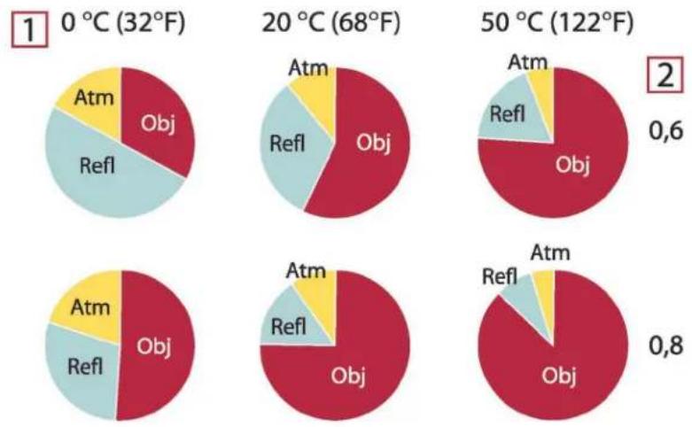
Figure 45.2 Relative magnitudes of radiation sources under varying measurement conditions (SW camera).
1: Object temperature; 2: Emittance; Obj: Object radiation; Refl: Reflected radiation; Atm: atmosphere radiation. Fixed parameters: = 0.88_eff T = 20^ (+68^) ; T_m = 20^ (+68^) .
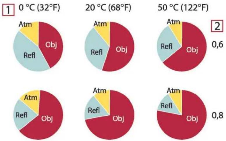
Figure 45.3 Relative magnitudes of radiation sources under varying measurement conditions (LW camera).
1: Object temperature; 2: Emittance; Obj: Object radiation; Refl: Reflected radiation; Atm: atmosphere radiation. Fixed parameters: = 0.88_effF = 20^ (+68°F); T_m = 20^ (+68°F).
This section presents a compilation of emissivity data from the infrared literature and measurements made by FLIR Systems.
46.1 References
- Mikaël A. Bramson: Infrared Radiation, A Handbook for Applications, Plenum press, N. Y
- William L. Wolfe, George J. Zissis: The Infrared Handbook, Office of Naval Research, Department of Navy, Washington, D.C.
- Madding, R. P.: Thermographic Instruments and systems. Madison, Wisconsin: University of Wisconsin – Extension, Department of Engineering and Applied Science.
- William L. Wolfe: Handbook of Military Infrared Technology, Office of Naval Research, Department of Navy, Washington, D.C.
- Jones, Smith, Probert: External thermography of buildings..., Proc. of the Society of Photo-Optical Instrumentation Engineers, vol.110, Industrial and Civil Applications of Infrared Technology, June 1977 London.
- Paljak, Pettersson: Thermography of Buildings, Swedish Building Research Institute, Stockholm 1972.
- Vlcek, J: Determination of emissivity with imaging radiometers and some emissivities at = 5 m . Photogrammetric Engineering and Remote Sensing.
- Kern: Evaluation of infrared emission of clouds and ground as measured by weather satellites, Defence Documentation Center, AD 617 417.
- Öhman, Claes: Emittansmätningar med AGEMA E-Box. Teknisk rapport, AGEMA 1999. (Emittance measurements using AGEMA E-Box. Technical report, AGEMA 1999.)
- Matteï, S., Tang-Kwor, E: Emissivity measurements for Nextel Velvet coating 811-21 between -36^ AND 82^ .
- Lohrengel & Todtenhaupt (1996)
- ITC Technical publication 32.
- ITC Technical publication 29.
- Schuster, Norbert and Kolobrodov, Valentin G. Infrarotthermographie. Berlin: Wiley-VCH, 2000.
Note The emissivity values in the table below are recorded using a shortwave (SW) camera. The values should be regarded as recommendations only and used with caution.
46.2 Tables
Table 46.1 T: Total spectrum; SW: 2–5 μm; LW: 8–14 μm, LLW: 6.5–20 μm; 1: Material; 2: Specification; 3: Temperature in °C; 4: Spectrum; 5: Emissivity: 6: Reference
| 1 2 3 4 5 | 6 | ||||
| 3M type 35 | Vinyl electrical tape (several colors) | < 80 | LW | ≈ 0.96 | 13 |
| 3M type 88 | Black vinyl electrical tape | < 105 | LW | ≈ 0.96 | 13 |
| 3M type 88 | Black vinyl electrical tape | < 105 | MW | < 0.96 | 13 |
| 3M type Super 33 + | Black vinyl electrical tape | < 80 | LW | ≈ 0.96 | 13 |
| Aluminum1 2 3 4 5 6 | anodized sheet | 100 | T | 0.55 | 2 |
| Aluminum anodized, black, dull | 70 | SW | 0.67 9 | ||
| Aluminum anodized, black, dull | 70 LW 0.95 9 | ||||
| Aluminum anodized, light gray, dull | 70 | SW | 0.61 9 | ||
| Aluminum anodized, light gray, dull | 70 LW 0.97 9 | ||||
| Aluminum as received, plate 100 T 0.09 4 | |||||
| Aluminum as received, sheet 100 T 0.09 2 | |||||
| Aluminum cast, blast cleaned | 70 | SW | 0.47 9 | ||
| Aluminum cast, blast cleaned | 70 LW 0.46 9 | ||||
| Aluminum dipped in HNO 3, plate | 100 T 0.05 4 | ||||
| Aluminum foil | 27 10 μm 0.04 3 | ||||
| Aluminum foil | 27 3 μm 0.09 3 | ||||
| Aluminum | oxidized, strongly | 50-500 | T | 0.2-0.3 | 1 |
| Aluminum polished | 50-100 | T 0.04-0.06 1 | |||
| Aluminum polished | plate 100 T 0.05 4 | ||||
| Aluminum polished | sheet 100 T 0.05 2 | ||||
| Aluminum rough surface | 20-50 | T 0.06-0.07 1 | |||
| Aluminum roughened | 27 10 μm 0.18 3 | ||||
| Aluminum roughened | 27 3 μm 0.28 3 | ||||
| Aluminum sheet, 4 | samples differently scratched | 70 | SW | 0.05-0.08 9 | |
| Aluminum sheet, 4 | samples differently scratched | 70 LW 0.03-0.06 9 | |||
| Aluminum vacuum deposited | 20 T 0.04 2 | ||||
| Aluminum weathered, heavily | 17 | SW | 0.83-0.94 5 | ||
| Aluminum bronze | 20 T 0.60 1 | ||||
| Aluminum hydroxide | powder | T 0.28 1 | |||
| Aluminum oxide | activated, powder | T 0.46 1 | |||
| Aluminum oxide | pure, powder (alumina) | T 0.16 1 | |||
| Asbestos | board | 20 T 0.96 1 | |||
| Asbestos | fabric | T 0.78 1 | |||
| Asbestos | floor tile | 35 | SW | 0.94 7 | |
| Asbestos | paper | 40-400 | T 0.93-0.95 1 | ||
| Asbestos powder T | 0.40-0.60 1 | ||||
| Asbestos slate 20 | T 0.96 1 | ||||
| Asphalt paving | 4 LLW 0.967 | 8 | |||
| Brass | dull, tarnished | 20-350 | T 0.22 1 | ||
| Brass | oxidized | 100 | T 0.61 2 | ||
| Brass | oxidized | 70 | SW | 0.04-0.09 9 | |
| Brass | oxidized | 70 LW 0.03-0.07 9 | |||
| Brass | oxidized at 600°C | 200-600 | T 0.59-0.61 1 | ||
| Brass | polished | 200 | T 0.03 1 | ||
| Brass | polished, highly | 100 | T 0.03 2 | ||
| Brass | rubbed with 80-grit emery | 20 T 0.20 2 | |||
| Brass | sheet, rolled | 20 T 0.06 1 | |||
| Brass | sheet, worked with emery | 20 T 0.2 | 1 | ||
| Brick | alumina | 17 | SW | 0.68 5 | |
| Brick | common | 17 | SW | 0.86-0.81 5 | |
| Brick | Dinas silica, glazed, rough | 1100 | T 0.85 1 | ||
| Brick | Dinas silica, refractory | 1000 | T 0.66 1 | ||
| Brick | Dinas silica, un-glazed, rough | 1000 | T 0.80 1 | ||
| Brick | firebrick | 17 | SW | 0.68 5 | |
| Brick | fireclay | 1000 | T 0.75 1 | ||
| Brick | fireclay | 1200 | T 0.59 1 | ||
| Brick | fireclay | 20 T 0.85 1 | |||
| Brick | masonry | 35 | SW | 0.94 7 | |
| Brick | masonry, plastered | 20 T 0.94 1 | |||
| Brick | red, common | 20 T 0.93 2 | |||
| Brick | red, rough | 20 T 0.88-0.93 1 | |||
| Brick | refractory, corundum | 1000 | T 0.46 1 | ||
| Brick | refractory, magnesite | 1000-1300 | T 0.38 1 | ||
| Brick | refractory, strongly radiating | 500-1000 T 0.8-0.9 | 1 | ||
| Brick | refractory, weakly radiating | 500-1000 T 0.65-0.75 1 | |||
| Brick | silica, 95% SiO | 1230 | T 0.66 1 | ||
| Brick | sillimanite, 33% SiO2, 64% AlO3 | 1500 | T 0.29 1 | ||
| Brick waterproof | 17 | SW | 0.87 5 | ||
| Bronze phosphor bronze 70 | SW | 0.08 9 | |||
| Bronze phosphor bronze 70 LW 0.06 9 | |||||
| Bronze polished 50 T 0.1 | 1 | ||||
| Bronze porous, rough 50–150 | T | 0.55 1 | |||
| Bronze powder | T | 0.76–0.80 | 1 | ||
| Carbon | candle soot | 20 T 0.95 | 2 | ||
| Carbon | charcoal powder | T | 0.96 1 | ||
| Carbon | graphite powder | T | 0.97 1 | ||
| Carbon | graphite, filed surface | 20 T 0.98 | 2 | ||
| Carbon | lampblack | 20–400 | T | 0.95–0.97 | 1 |
| Chipboard | untreated | 20 | SW | 0.90 6 | |
| Chromium | polished 50 T | 0.10 1 | |||
| Chromium | polished | 500–1000 | T | 0.28–0.38 | 1 |
| Clay | fired | 70 T 0.91 | 1 | ||
| Cloth | black | 20 T 0.98 | 1 | ||
| Concrete | 20 T 0.92 | 2 | |||
| Concrete | dry | 36 SW | 0.95 7 | ||
| Concrete | rough | 17 SW | 0.97 5 | ||
| Concrete | walkway | 5 | LLW | 0.974 | 8 |
| Copper | commercial, burnished | 20 T 0.07 | 1 | ||
| Copper | electrolytic, carefully polished | 80 T 0.018 | 1 | ||
| Copper | electrolytic, polished | -34 | T | 0.006 | 4 |
| Copper | molten | 1100–1300 | T | 0.13–0.15 | 1 |
| Copper | oxidized | 50 T 0.6–0.7 | 1 | ||
| Copper | oxidized to blackness | T | 0.88 1 | ||
| Copper | oxidized, black | 27 T 0.78 | 4 | ||
| Copper | oxidized, heavily | 20 T 0.78 | 2 | ||
| Copper | polished 50–100 | T | 0.02 1 | ||
| Copper | polished 100 | T | 0.03 2 | ||
| Copper | polished, commercial | 27 T 0.03 | 4 | ||
| Copper | polished, mechanical | 22 T 0.015 | 4 | ||
| Copper | pure, carefully prepared surface | 22 T 0.008 | 4 | ||
| Copper | scraped | 27 T 0.07 | 4 | ||
| Copper dioxide | powder T 0.84 1 | ||||
| Copper oxide | red, powder T 0.70 1 | ||||
| Ebonite T 0.89 1 | |||||
| Emery | coarse 80 T 0.85 1 | ||||
| Enamel | 20 T 0.9 | 1 | |||
| Enamel | lacquer | 20 T 0.85–0.95 | 1 | ||
| Fiber board | hard, untreated | 20 | SW | 0.85 6 | |
| Fiber board | masonite | 70 | SW | 0.75 9 | |
| Fiber board | masonite | 70 LW 0.88 | 9 | ||
| Fiber board | particle board | 70 | SW | 0.77 9 | |
| Fiber board | particle board | 70 LW 0.89 | 9 | ||
| Fiber board | porous, untreated | 20 | SW | 0.85 6 | |
| Glass pane (float glass) | non-coated | 20 LW 0.97 | 14 | ||
| Gold | polished | 130 | T 0.018 | 1 | |
| Gold | polished, carefully | 200–600 | T 0.02–0.03 | 1 | |
| Gold | polished, highly | 100 | T 0.02 2 | ||
| Granite | polished | 20 LLW 0.849 | 8 | ||
| Granite | rough | 21 | LLW | 0.879 | 8 |
| Granite | rough, 4 different samples | 70 | SW | 0.95–0.97 | 9 |
| Granite | rough, 4 different samples | 70 LW 0.77–0.87 | 9 | ||
| Gypsum | 20 T 0.8–0.9 | 1 | |||
| Ice: See Water | |||||
| Iron and steel | cold rolled | 70 | SW | 0.20 9 | |
| Iron and steel | cold rolled | 70 LW 0.09 | 9 | ||
| Iron and steel | covered with red rust | 20 T 0.61–0.85 | 1 | ||
| Iron and steel | electrolytic | 100 | T | 0.05 | 4 |
| Iron and steel | electrolytic | 22 T 0.05 4 | |||
| Iron and steel | electrolytic | 260 | T | 0.07 | 4 |
| Iron and steel | electrolytic, carefully polished | 175–225 | T 0.05–0.06 | 1 | |
| Iron and steel | freshly worked with emery | 20 T 0.24 1 | |||
| Iron and steel | ground sheet | 950–1100 | T | 0.55–0.61 | 1 |
| Iron and steel | heavily rusted sheet | 20 T 0.69 2 | |||
| Iron and steel | hot rolled | 130 | T 0.60 | 1 | |
| Iron and steel | hot rolled | 20 T 0.77 1 | |||
| Iron and steel | oxidized | 100 | T 0.74 | 4 | |
| Iron and steel oxidized 100 T 0.74 1 | |||||
| Iron and steel oxidized 1227 T 0.89 4 | |||||
| Iron and steel oxidized 125-525 T 0.78-0.82 1 | |||||
| Iron and steel oxidized 200 T 0.79 2 | |||||
| Iron and steel oxidized 200-600 T 0.80 1 | |||||
| Iron and steel oxidized strongly 50 | T 0.88 1 | ||||
| Iron and steel oxidized strongly 500 | T 0.98 1 | ||||
| Iron and steel polished 100 | T 0.07 2 | ||||
| Iron and steel polished | 400-1000 | T | 0.14-0.38 | 1 | |
| Iron and steel polished sheet | 750-1050 | T | 0.52-0.56 | 1 | |
| Iron and steel rolled sheet 50 | T 0.56 1 | ||||
| Iron and steel rolled, freshly | 20 | T 0.24 1 | |||
| Iron and steel rough, plane surface | 50 | T 0.95-0.98 1 | |||
| Iron and steel rusted red, sheet 22 | T 0.69 4 | ||||
| Iron and steel rusted, heavily 17 | SW | 0.96 5 | |||
| Iron and steel rusty, red 20 | T 0.69 1 | ||||
| Iron and steel shiny oxide layer, sheet, | 20 | T 0.82 1 | |||
| Iron and steel shiny, etched 150 | T 0.16 1 | ||||
| Iron and steel wrought, carefully polished | 40-250 | T 0.28 1 | |||
| Iron galvanized | heavily oxidized | 70 | SW | 0.64 9 | |
| Iron galvanized | heavily oxidized | 70 | LW | 0.85 | 9 |
| Iron galvanized | sheet | 92 | T 0.07 4 | ||
| Iron galvanized | sheet, burnished | 30 | T | 0.23 | 1 |
| Iron galvanized | sheet, oxidized | 20 | T | 0.28 | 1 |
| Iron tinned | sheet | 24 | T | 0.064 | 4 |
| Iron, cast | casting | 50 | T 0.81 1 | ||
| Iron, cast | ingots | 1000 T 0.95 1 | |||
| Iron, cast | liquid | 1300 T 0.28 1 | |||
| Iron, cast | machined | 800-1000 | T | 0.60-0.70 | 1 |
| Iron, cast | oxidized 100 T 0.64 2 | ||||
| Iron, cast | oxidized 260 T 0.66 4 | ||||
| Iron, cast | oxidized 38 | T 0.63 4 | |||
| Iron, cast | oxidized 538 T 0.76 4 | ||||
| Iron, cast | oxidized at 600°C | 200-600 T 0.64-0.78 | 1 | ||
| Iron, cast | polished | 200 T 0.21 1 | |||
| Iron, cast | polished | 38 | T 0.21 4 | ||
| Iron, cast | polished | 40 | T 0.21 2 | ||
| Iron, cast unworked | 900-1100 T 0.87-0.95 1 | ||||
| Krylon Ultra-flat black 1602 | Flat black Room temperature up to 175 | LW ≈ 0.96 12 | |||
| Krylon Ultra-flat black 1602 | Flat black Room temperature up to 175 | MW | ≈ 0.97 12 | ||
| Lacquer | 3 colors sprayed on Aluminum | 70 | SW | 0.50-0.53 9 | |
| Lacquer | 3 colors sprayed on Aluminum | 70 | LW 0.92 | -0.94 9 | |
| Lacquer | Aluminum on rough surface | 20 | T 0.4 | 1 | |
| Lacquer | bakelite | 80 | T | 0.83 | 1 |
| Lacquer | black, dull 40-100 | T 0.96-0.98 1 | |||
| Lacquer | black, matte 100 | T 0.97 | 2 | ||
| Lacquer | black, shiny, sprayed on iron | 20 | T 0.87 | 1 | |
| Lacquer | heat-resistant 100 | T 0.92 | 1 | ||
| Lacquer | white | 100 | T | 0.92 | 2 |
| Lacquer | white | 40-100 | T | 0.8-0.95 | 1 |
| Lead | oxidized at 200°C | 200 | T 0.63 | 1 | |
| Lead | oxidized, gray | 20 | T | 0.28 | 1 |
| Lead | oxidized, gray | 22 | T | 0.28 | 4 |
| Lead | shiny | 250 | T | 0.08 | 1 |
| Lead | unoxidized, polished | 100 | T 0.05 | 4 | |
| Lead red | 100 | T 0.93 | 4 | ||
| Lead red, powder | 100 | T 0.93 | 1 | ||
| Leather | tanned | T 0.75-0.80 1 | |||
| Lime | T 0.3-0.4 | 1 | |||
| Magnesium | 22 | T 0.07 | 4 | ||
| Magnesium | 260 | T 0.13 | 4 | ||
| Magnesium | 538 | T 0.18 | 4 | ||
| Magnesium | polished | 20 | T | 0.07 | 2 |
| Magnesium powder | T 0.86 | 1 | |||
| Molybdenum | 1500-2200 | T 0.19-0.26 1 | |||
| Molybdenum | 600-1000 T 0.08-0.13 1 | ||||
| Molybdenum | filament | 700-2500 T 0.1-0.3 | 1 | ||
| Mortar | 17 | SW | 0.87 | 5 | |
| Mortar | dry | 36 | SW | 0.94 | 7 |
| Nextel Velvet 811-21 Black | Flat black -60-150 | LW > 0 | 97 10 and | 11 | |
| Nichrome rolled 700 T 0.25 1 | |||||
| Nichrome sandblasted 700 T 0.70 1 | |||||
| Nichrome wire, clean 50 | T 0.65 1 | ||||
| Nichrome wire, clean 500-1000 | T 0.71-0.79 | 1 | |||
| Nichrome | wire, oxidized | 50-500 | T | 0.95-0.98 | 1 |
| Nickel | bright matte | 122 T 0.041 | 4 | ||
| Nickel | commercially pure, polished | 100 T 0.045 | 1 | ||
| Nickel | commercially pure, polished | 200-400 | T 0.07-0.09 | 1 | |
| Nickel | electrolytic 22 | T 0.04 | 4 | ||
| Nickel | electrolytic 260 T 0.07 4 | ||||
| Nickel | electrolytic 38 | T 0.06 | 4 | ||
| Nickel | electrolytic 538 T 0.10 4 | ||||
| Nickel | electroplated on iron, polished | 22 | T 0.045 | 4 | |
| Nickel | electroplated on iron, unpolished | 20 | T 0.11-0.40 | 1 | |
| Nickel | electroplated on iron, unpolished | 22 | T 0.11 4 | ||
| Nickel | electroplated, polished | 20 | T 0.05 2 | ||
| Nickel | oxidized | 1227 | T 0.85 4 | ||
| Nickel | oxidized | 200 T 0.37 2 | |||
| Nickel | oxidized | 227 T 0.37 4 | |||
| Nickel | oxidized at 600°C | 200-600 | T 0.37-0.48 | 1 | |
| Nickel | polished | 122 T 0.045 | 4 | ||
| Nickel | wire | 200-1000 | T | 0.1-0.2 | 1 |
| Nickel oxide | 1000-1250 | T 0.75-0.86 | 1 | ||
| Nickel oxide | 500-650 | T 0.52-0.59 | 1 | ||
| Oil, lubricating | 0.025 mm film | 20 | T 0.27 2 | ||
| Oil, lubricating | 0.050 mm film | 20 | T 0.46 2 | ||
| Oil, lubricating | 0.125 mm film | 20 | T 0.72 2 | ||
| Oil, lubricating | film on Ni base: Ni base only | 20 | T 0.05 2 | ||
| Oil, lubricating | thick coating | 20 | T 0.82 2 | ||
| Paint | 8 different colors and qualities | 70 | SW | 0.88-0.96 | 9 |
| Paint | 8 different colors and qualities | 70 | LW | 0.92-0.94 | 9 |
| Paint | Aluminum, various ages | 50-100 | T 0.27-0.67 | 1 | |
| Paint | cadmium yellow | T 0.28-0.33 | 1 | ||
| Paint chrome green | T 0.65–0.70 1 | ||||
| Paint cobalt blue T | 0.7–0.8 1 | ||||
| Paint oil 17 | SW | 0.87 | 5 | ||
| Paint oil based, average of 16 colors | 100 | T 0.94 | 2 | ||
| Paint oil, black flat | 20 | SW | 0.94 | 6 | |
| Paint oil, black gloss | 20 | SW | 0.92 | 6 | |
| Paint oil, gray flat | 20 | SW | 0.97 | 6 | |
| Paint oil, gray gloss | 20 | SW | 0.96 | 6 | |
| Paint oil, various colors | 100 | T 0.92–0.96 | 1 | ||
| Paint plastic, black | 20 | SW | 0.95 | 6 | |
| Paint plastic, white | 20 | SW | 0.84 | 6 | |
| Paper | 4 different colors | 70 | SW | 0.68–0.74 9 | |
| Paper | 4 different colors | 70 | LW | 0.92–0.94 9 | |
| Paper | black | T 0.90 | 1 | ||
| Paper | black, dull | T 0.94 | 1 | ||
| Paper | black, dull 70 | SW | 0.86 | 9 | |
| Paper | black, dull | 70 | LW | 0.89 | 9 |
| Paper | blue, dark | T 0.84 | 1 | ||
| Paper | coated with black lacquer | T 0.93 | 1 | ||
| Paper | green | T 0.85 | 1 | ||
| Paper | red | T 0.76 | 1 | ||
| Paper | white | 20 | T 0.7–0.9 1 | ||
| Paper | white bond | 20 | T | 0.93 | 2 |
| Paper | white, 3 different glosses | 70 | SW | 0.76–0.78 9 | |
| Paper | white, 3 different glosses | 70 | LW | 0.88–0.90 9 | |
| Paper | yellow | T 0.72 | 1 | ||
| Plaster | 17 | SW | 0.86 | 5 | |
| Plaster | plasterboard, untreated | 20 | SW | 0.90 | 6 |
| Plaster | rough coat | 20 | T | 0.91 | 2 |
| Plastic | glass fibre laminate (printed circ. board) | 70 | SW | 0.94 | 9 |
| Plastic | glass fibre laminate (printed circ. board) | 70 | LW | 0.91 | 9 |
| Plastic | polyurethane isolation board | 70 | LW | 0.55 | 9 |
| Plastic polyurethane | iso-lation board | 70 | SW | 0.29 9 | |
| Plastic PVC, plastic | floor,dull, structured | 70 | SW | 0.94 9 | |
| Plastic PVC, plastic | floor,dull, structured | 70 LW 0.93 9 | |||
| Platinum 100 T 0.05 4 | |||||
| Platinum 1000-1500 | T 0.14-0.18 1 | ||||
| Platinum 1094 | T 0.18 4 | ||||
| Platinum 17 T 0.016 | 4 | ||||
| Platinum 22 T 0.03 4 | |||||
| Platinum 260 T 0.06 4 | |||||
| Platinum 538 T 0.10 4 | |||||
| Platinum | pure, polished | 200-600 | T | 0.05-0.10 | 1 |
| Platinum | ribbon | 900-1100 | T | 0.12-0.17 | 1 |
| Platinum | wire | 1400 | T 0.18 1 | ||
| Platinum | wire | 500-1000 | T | 0.10-0.16 | 1 |
| Platinum | wire | 50-200 | T | 0.06-0.07 | 1 |
| Porcelain | glazed 20 T 0.92 | ||||
| Porcelain | white, shiny | T 0.70-0.75 1 | |||
| Rubber | hard | 20 T 0.95 1 | |||
| Rubber | soft, gray, rough | 20 T 0.95 1 | |||
| Sand | T 0.60 1 | ||||
| Sand | 20 T 0.90 2 | ||||
| Sandstone | polished | 19 | LLW | 0.909 | 8 |
| Sandstone | rough | 19 LLW 0.935 | 8 | ||
| Silver | polished | 100 T 0.03 2 | |||
| Silver | pure, polished | 200-600 | T | 0.02-0.03 | 1 |
| Skin | human | 32 T 0.98 2 | |||
| Slag | boiler | 0-100 | T 0.97-0.93 1 | ||
| Slag | boiler | 1400-1800 | T 0.69-0.67 1 | ||
| Slag | boiler | 200-500 | T | 0.89-0.78 | 1 |
| Slag | boiler | 600-1200 | T | 0.76-0.70 | 1 |
| Snow: See Water | |||||
| Soil | dry | 20 T 0.92 2 | |||
| Soil saturated with water | 20 T 0.95 2 | ||||
| Stainless steel | alloy, 8% Ni, 18% Cr | 500 T 0.35 1 | |||
| Stainless steel | rolled | 700 T 0.45 1 | |||
| Stainless steel | sandblasted | 700 T 0.70 1 | |||
| Stainless steel | sheet, polished | 70 SW | 0.18 9 | ||
| Stainless steel | sheet, polished 70 | LW 0.14 9 | |||
| Stainless steel sheet, untreated, somewhat scratched | 70 | SW | 0.30 9 | ||
| Stainless steel | sheet, untreated, somewhat scratched | 70 LW 0.28 9 | |||
| Stainless steel type | 18-8, buffed | 20 T 0.16 2 | |||
| Stainless steel type | 18-8, oxidized at 800°C | 60 T 0.85 2 | |||
| Stucco rough, lime | 10-90 | T 0.91 1 | |||
| Styrofoam | insulation | 37 SW | 0.60 7 | ||
| Tar | T 0.79-0.84 | 1 | |||
| Tar | paper | 20 T 0.91-0.93 | 1 | ||
| Tile | glazed | 17 | SW | 0.94 5 | |
| Tin | burnished | 20-50 | T | 0.04-0.06 | 1 |
| Tin | tin-plated sheet iron | 100 | T 0.07 2 | ||
| Titanium | oxidized at 540°C | 1000 | T 0.60 1 | ||
| Titanium | oxidized at 540°C | 200 | T 0.40 1 | ||
| Titanium | oxidized at 540°C | 500 | T 0.50 1 | ||
| Titanium | polished | 1000 | T 0.36 1 | ||
| Titanium | polished | 200 | T 0.15 1 | ||
| Titanium | polished | 500 | T 0.20 1 | ||
| Tungsten | 1500-2200 | T 0.24-0.31 | 1 | ||
| Tungsten | 200 | T 0.05 1 | |||
| Tungsten | 600-1000 | T 0.1-0.16 | 1 | ||
| Tungsten | filament | 3300 | T 0.39 1 | ||
| Varnish | flat | 20 | SW | 0.93 6 | |
| Varnish | on oak parquet floor | 70 | SW | 0.90 9 | |
| Varnish | on oak parquet floor | 70 LW 0.90-0.93 | 9 | ||
| Wallpaper | slight pattern, light gray | 20 | SW | 0.85 6 | |
| Wallpaper | slight pattern, red | 20 | SW | 0.90 6 | |
| Water | distilled | 20 T 0.96 2 | |||
| Water | frost crystals | -10 | T 0.98 2 | ||
| Water | ice, covered with heavy frost | 0 T 0.98 1 | |||
| Water | ice, smooth | 0 T 0.97 1 | |||
| Water | ice, smooth | -10 | T 0.96 2 | ||
| Water | layer >0.1 mm thick | 0-100 | T 0.95-0.98 | 1 | |
| Water | snow | T 0.8 1 | |||
| Water | snow -10 T 0.85 2 | ||||
| Wood 17 | SW | 0.98 5 | |||
| Wood 19 LLW | 0.962 | 8 | |||
| Wood | ground | T 0.5-0.7 | 1 | ||
| Wood | pine, 4 different samples | 70 | SW | 0.67-0.75 | 9 |
| Wood | pine, 4 different samples | 70 LW 0.81-0.89 | 9 | ||
| Wood | planed | 20 T 0.8-0.9 | 1 | ||
| Wood | planed oak | 20 T 0.90 2 | |||
| Wood | planed oak | 70 | SW | 0.77 9 | |
| Wood | planed oak | 70 LW 0.88 | 9 | ||
| Wood | plywood, smooth, dry | 36 | SW | 0.82 7 | |
| Wood | plywood, untreated | 20 | SW | 0.83 6 | |
| Wood | white, damp 20 T | 0.7-0.8 | 1 | ||
| Zinc | oxidized at 400°C | 400 | T 0.11 1 | ||
| Zinc | oxidized surface | 1000-1200 | T 0.50-0.60 | 1 | |
| Zinc | polished | 200-300 | T | 0.04-0.05 | 1 |
| Zinc | sheet | 50 T 0.20 1 | |||
A note on the technical production of this publication
This publication was produced using XML — the eXtensible Markup Language. For more information about XML, please visit http://www.w3.org/XML/
A note on the typeface used in this publication
This publication was typeset using Linotype Helvetica™ World. Helvetica™ was designed by Max Miedinger (1910–1980)
LOEF (List Of Effective Files)
| T501212.xml; en-US; AN; 42241; 2017-04-27 |
| T505998.xml; en-US; 37094; 2016-08-31 |
| T505776.xml; en-US; 39513; 2017-01-18 |
| T505013.xml; en-US; 39689; 2017-01-25 |
| T506043.xml; en-US; 39513; 2017-01-18 |
| T505251.xml; en-US; 39513; 2017-01-18 |
| T505995.xml; en-US; 39513; 2017-01-18 |
| T505940.xml; en-US; 39513; 2017-01-18 |
| T505941.xml; en-US; 40564; 2017-02-24 |
| T505252.xml; en-US; 39860; 2017-01-31 |
| T505942.xml; en-US; 40564; 2017-02-24 |
| T505943.xml; en-GB; 40565; 2017-02-24 |
| T505975.xml; en-US; 39513; 2017-01-18 |
| T505944.xml; en-US; 39513; 2017-01-18 |
| T505945.xml; en-US; 40565; 2017-02-24 |
| T505946.xml; en-US; 41111; 2017-03-13 |
| T505240.xml; en-US; 39860; 2017-01-31 |
| T506013.xml; en-US; 39513; 2017-01-18 |
| T505310.xml; en-US; 39513; 2017-01-18 |
| T505403.xml; en-US; 39513; 2017-01-18 |
| T505967.xml; en-US; 39513; 2017-01-18 |
| T505991.xml; en-US; 39861; 2017-01-31 |
| T505470.xml; en-US; 39513; 2017-01-18 |
| T505485.xml; en-US; 39513; 2017-01-18 |
| T505970.xml; en-US; 39513; 2017-01-18 |
| T505432.xml; en-US; 39513; 2017-01-18 |
| T505007.xml; en-US; 39512; 2017-01-18 |
| T506125.xml; en-US; 40753; 2017-03-02 |
| T505000.xml; en-US; 39687; 2017-01-25 |
| T506051.xml; en-US; 40460; 2017-02-20 |
| T505005.xml; en-US; 39512; 2017-01-18 |
| T505001.xml; en-US; 39512; 2017-01-18 |
| T505006.xml; en-US; 39581; 2017-01-20 |
| T505002.xml; en-US; 39512; 2017-01-18 |
Website
http://www.flir.com
Customer support
http://support.flir.com
Copyright
© 2017, FLIR Systems, Inc. All rights reserved worldwide.
Disclaimer
Specifications subject to change without further notice. Models and accessories subject to regional market considerations. License procedures may apply. Products described herein may be subject to US Export Regulations. Please refer to exportquestions@flir.com with any questions.

- User's manual FLIR GFx3xx series
- Important note
- Důležitá poznámka
- Table of contents
- Disclaimers ....1
- Safety information ....4
- Notice to user 12
- Customer help 14
- Conditions of Use for Ex Equipment 16
- Important note about training and applications.... 17
- Important information about FLIR GFx3xx series service 18
- List of accessories and services 19
- Introduction....23
- Example images....24
- Quick start guide....25
- FLIR GFx3xx series general instrument check 34
- A note about ergonomics 35
- Camera parts 37
- Screen elements 44
- ieving a good image 46
- Terms, laws, and definitions.... 121
- Thermographic measurement techniques 123
- About calibration.... 128
- History of infrared technology.... 131
- Theory of thermography.... 134
- The measurement formula.... 142
- Emissivity tables 146
- 1
- Disclaimers
- Legal disclaimer
- U.S. Government Regulations
- Copyright
- Quality assurance
- Patents
- EULA Terms
- EULA Terms
- 2
- Safety information
- Cautions and warnings related to a classified (hazardous) area
- General cautions and warnings
- Table of entity parameters
- Battery warning label
- Laser warning label
- Laser rules and regulations
- Compliance marking
- Figure
- Explanation
- Certifications
- Explosive (hazardous) environment
- Safety
- User-to-user forums
- Calibration
- Accuracy
- Disposal of electronic waste
- Training
- Documentation updates
- Note about authoritative versions
- 4
- Customer help
- FLIR Customer Support Center
- FLIR Customer support
- Get the most out of your FLIR products
- Search All Answers
- General
- Submitting a question
- Downloads
- Conditions of Use for Ex Equipment
- Important note about training and applications
- General
- 7
- Important information about FLIR GFx3xx series service
- List of accessories and services
- Introduction
- Example images
- General
- Images
- Quick start guide
- Starting the camera for the first time
- Note
- Detecting a gas leak
- Procedure
- Related topics
- Detecting a temperature
- Procedure
- Related topics
- FLIR GFx3xx series general instrument check
- A note about ergonomics
- General
- Figure
- Related topics
- Camera parts
- View from the left
- Explanation
- View from the right
- Explanation
- S button (Preview/Save).
- View from the rear
- Explanation
- View from the rear with open cover
- Explanation
- WARNING
- Battery condition LED indicator
- Figure
- Explanation
- Power LED indicator
- Figure
- Explanation
- Laser pointer
- General
- Figure
- Laser warning label
- Laser rules and regulations
- Serial number
- General
- Figure
- Screen elements
- Mode selector
- Figure
- Explanation
- Result table and measurement tools
- Figure
- Explanation
- Toolbox, indicators, and other objects
- Figure
- Explanation
- Achieving a good image
- General
- Adjusting the infrared camera focus
- Procedure
- Adjusting an image
- General
- Explanation of the adjustment methods
- Procedure (Auto)
- Figure
- Procedure (HSM)
- Procedure (Manual)
- Selecting a suitable temperature range
- About temperature ranges
- General
- Understanding the temperature scale
- Figure
- Explanation
- Changing the temperature range
- Procedure
- Selecting a suitable color palette
- Procedure
- Enabling or disabling histogram mode
- General
- Procedure
- Enabling or disabling inverted color palette
- Procedure
- Changing object parameters
- General
- Types of parameters
- Recommended values
- Procedure
- Related topics
- Connecting external devices
- General
- Figure
- Explanation
- Formatting memory cards
- Handling the camera
- Charging the camera battery
- Charging the battery using the power supply cable
- Procedure
- Related topics
- Charging the battery using the stand-alone battery charger
- Procedure
- Related topics
- Installing and removing the camera battery
- Installing the battery
- Procedure
- Removing the battery
- Procedure
- Turning on the camera
- Procedure
- Turning off the camera
- Procedure
- Adjusting the viewing angle of the viewfinder
- General
- Figure
- Procedure
- Adjusting the viewfinder's dioptric correction
- General
- Procedure
- Adjusting the camera grip
- General
- Procedure
- Opening the display
- Adjusting the viewing angle of the display
- General
- Procedure
- Adjusting the infrared camera focus
- Figure
- Procedure
- Using the zoom function
- General
- Procedure
- Operating the laser pointer
- Procedure
- Laser warning label
- Laser rules and regulations
- Assigning functions to the programmable button
- General
- Procedure
- Working with views and images
- Saving infrared images
- General
- Image capacity
- Saving an infrared image directly to an SD Memory Card
- General
- Procedure
- Previewing and saving an infrared image to an SD Memory Card
- General
- Procedure
- Opening an image
- General
- Procedure
- Changing settings related to image presentation
- General
- ZOOM
- Procedure
- Editing a saved image
- General
- Procedure
- Deleting a file
- Procedure
- Working with measurement tools
- Laying out a measurement tool
- General
- Procedure
- Moving or resizing a measurement tool
- General
- Procedure
- Creating & setting up a difference calculation
- General
- Procedure
- Changing object parameters
- General
- Types of parameters
- Recommended values
- Procedure
- Related topics
- 21
- Programming the camera
- General
- Procedure
- General
- Procedure
- Changing settings
- General
- Procedure
- 24
- Technical data
- Online field-of-view calculator
- Note about technical data
- Note about authoritative versions
- FLIR GFx320 14.5° fixed lens
- FLIR GFx320 24° fixed lens
- Mechanical drawings
- EU Declaration of conformity
- Directives:
- Standards:
- Notified Body
- MET Compliance Data Report (truncated)
- Compliance Test Data Report
- FLIR Systems AB
- /Element Materials Technology
- MET Laboratories, Inc.
- IEC/IECEE/Intertek Test Report (truncated)
- IEC/IECEE/Intertek CB Test Certificate
- IEC SYSTEM FOR MUTUAL RECOGNITION OF TEST CERTIFICATES FOR ELECTRICAL EQUIPMENT (IECEE) CB SCHEME
- Additional information (if necessary)
- MET Laboratories Test Certificate (truncated)
- FLIR SYSTEMS AB, GFx320 Optical Gas Imaging Camera
- MET Laboratories Letter of Certification
- Element Type Examination Certificate (truncated)
- TYPE EXAMINATION CERTIFICATE
- Product or Protective System Intended for use in Potentially Explosive Atmospheres Directive 2014/34/EU – Annex VIII
- IECEx Technical Report: GB/EMT/ExTR16.0015/00
- IECEx Quality Assessment Report: GB/EMT/QAR16.0003/00
- Cleaning the camera
- Camera housing, cables, and other items
- Liquids
- Equipment
- Procedure
- CAUTION
- Infrared lens
- Liquids
- Equipment
- Procedure
- Cooler maintenance
- General
- Signs to watch for
- General
- Gases that can be detected by FLIR GFx3xx
- Why do some gases absorb infrared energy?
- About FLIR Systems
- More than just an infrared camera
- Sharing our knowledge
- Supporting our customers
- Terms, laws, and definitions
- Thermographic measurement techniques
- Introduction
- Emissivity
- Finding the emissivity of a sample
- Step 1: Determining reflected apparent temperature
- Method 1: Direct method
- Method 2: Reflector method
- Step 2: Determining the emissivity
- Reflected apparent temperature
- Distance
- Relative humidity
- Other parameters
- Introduction
- Definition—what is calibration?
- Camera calibration at FLIR Systems
- The differences between a calibration performed by a user and that performed directly at FLIR Systems
- Calibration, verification and adjustment
- Non-uniformity correction
- Thermal image adjustment (thermal tuning)
- History of infrared technology
- Theory of thermography
- Introduction
- The electromagnetic spectrum
- Blackbody radiation
- Wien's displacement law
- Stefan-Boltzmann's law
- Non-blackbody emitters
- Infrared semi-transparent materials
- The measurement formula
- References
- Tables
- A note on the technical production of this publication
- A note on the typeface used in this publication
- LOEF (List Of Effective Files)
Brand : FLIR
Model : GFx320
Category : Measurement