
E85 - Measurement FLIR - Free user manual and instructions
Find the device manual for free E85 FLIR in PDF.


| Product Type | Thermal Imaging Camera |
| Brand | FLIR |
| Model | E85 |
| Thermal Resolution | 480 × 360 pixels |
| Temperature Range | -20°C to 1200°C |
| Thermal Sensitivity (NETD) | < 0.03°C (30 mK) |
| Field of View | 24° × 18° |
| Minimum Focus Distance | 0.3 m (1 ft) |
| Display | 4.3" (640 × 480) touchscreen |
| Image Modes | Thermal, Visual, MSX, Picture-in-Picture |
| Digital Zoom | 1–8× continuous |
| Storage | Removable SD card (up to 32 GB) |
| Battery Type | Rechargeable Li-ion |
| Battery Life | Up to 3.5 hours |
| Weight (including battery) | Approx. 1.2 kg (2.6 lbs) |
| Dimensions (L × W × H) | 249 × 118 × 112 mm (9.8" × 4.6" × 4.4") |
| Waterproof Rating | IP54 |
| Drop Test | 2 m (6.6 ft) |
| Warranty | 2 years (battery 1 year) |
| Included Accessories | Hard case, battery, charger, USB cable, SD card, wrist strap, printed documentation |
| Cleaning | Wipe with a soft, dry cloth. Do not use solvents. |
| Safety | Laser class 1 product. Do not point laser at eyes. |
Frequently Asked Questions - E85 FLIR
User questions about E85 FLIR
0 question about this device. Answer the ones you know or ask your own.
Ask a new question about this device
Download the instructions for your Measurement in PDF format for free! Find your manual E85 - FLIR and take your electronic device back in hand. On this page are published all the documents necessary for the use of your device. E85 by FLIR.
USER MANUAL E85 FLIR
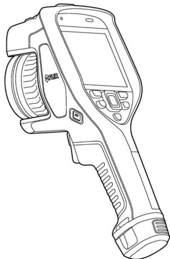
User's manual FLIR Exx series
natural_image
Line drawing of a medical imaging device with a screen and lens (no text or symbols)Important note
Before operating the device, you must read, understand, and follow all instructions, warnings, cautions, and legal disclaimers.
Důležitá poznámka
1.1 Legal disclaimer 1
1.2 U.S. Government Regulations.... 1
1.3 Patents 1
1.4 Quality assurance .... 1
1.5 Third-party licenses.... 1
1.6 Usage statistics .... 1
1.7 Copyright 1
2 Safety information ....2
3 Notice to user 6
3.1 Online documentation.... 6
3.2 Register your camera....6
3.3 Accuracy 6
3.4 Calibration.... 6
3.5 Training 6
3.6 Important note about this manual....6
3.7 Note about authoritative versions.... 7
3.8 Disposal of electronic waste 7
4 Customer help 8
4.1 General 8
4.2 Submitting a question 8
4.3 Downloads 8
5 Quick start guide ....9
5.1 To keep in mind 9
6 Camera overview.... 11
6.1 View from the front 11
6.2 View from the rear.... 13
6.3 Laser distance meter and laser pointer 14
6.3.1 Laser transmitter and receiver.... 15
6.3.2 Difference in position 15
6.3.3 Laser warning label.... 16
6.3.4 Laser rules and regulations 17
6.4 Screen elements 17
6.4.1 General.... 17
6.4.2 Menu system.... 17
6.4.3 Status icons and indicators.... 18
6.4.4 Swipe-down menu.... 18
6.4.5 Image overlay information 19
6.5 Navigating the menu system.... 20
6.5.1 Navigating using the navigation pad 20
7 Handling the camera.... 22
7.1 Charging the battery 22
7.1.1 General 22
7.1.2 Using the stand-alone battery charger to charge the battery 22
7.1.3 Using the USB battery charger to charge the battery 22
7.1.4 Charging the battery using a USB cable connected to a computer.... 24
7.2 Removing the battery.... 25
7.3 Turning on and turning off the camera.... 26
7.4 Adjusting the thermal camera focus 26
7.4.1 Manual focus.... 26
7.4.2 Autofocus 27
7.4.3 Continuous autofocus 29
7.5 Operating the laser distance meter 29
7.5.1 General.... 29
7.5.2 Procedure 30
7.6 Measuring areas.... 31
7.6.1 General.... 31
7.6.2 Procedure 32
7.7 Connecting external devices and storage media 32
7.8 Moving files to a computer 33
7.8.1 Related topics 35
7.9 Programmable button 36
7.9.1 Programmable button options 36
7.10 Using the camera lamp as a flash 37
7.11 Hand strap 38
7.11.1 Mounting the hand strap 40
7.12 Lanyard strap.... 43
7.13 Wrist strap.... 44
7.14 Front protection 47
7.15 Changing camera lenses 48
7.16 Calibrating the lens-camera combination 53
7.16.1 Introduction.... 53
7.16.2 AutoCal procedure 54
7.17 Calibrating the compass.... 57
8 Saving and working with images 58
8.1 About image files 58
8.1.1 General.... 58
8.1.2 File-naming convention 58
8.1.3 Storage capacity 58
8.1.4 About UltraMax.... 58
8.2 Saving an image 59
8.3 Previewing an image 59
8.4 Opening a saved image.... 60
8.5 Editing a saved image.... 60
8.5.1 Related topics 61
8.6 Displaying the image information.... 61
8.7 Zooming an image 61
8.8 Deleting images 61
8.9 Resetting the image counter.... 62
9 Cloud connectivity.... 63
9.1 Uploading to FLIR Ignite 63
9.2 Connecting to internet.... 63
9.2.1 Connecting to Wi-Fi 63
9.2.2 Connecting via Bluetooth 63
9.3 Creating a FLIR Ignite account.... 64
9.4 Pairing with FLIR Ignite.... 64
9.5 Automatic upload.... 64
9.6 Manual upload 64
9.6.1 Uploading an image/video file 64
9.6.2 Uploading multiple files.... 64
9.6.3 Uploading folders 65
9.7 Accessing FLIR Ignite 65
10 Working with the image archive.... 66
10.1 General 66
10.2 Opening image and video files 66
10.3 Creating a new folder.... 66
10.4 Renaming a folder.... 67
10.5 Changing the active folder 67
10.6 Moving files between folders 67
10.7 Uploading files and folders.... 67
10.8 Deleting a folder 67
10.9 Deleting an image or video file 68
10.10 Deleting multiple files.... 68
10.11 Deleting all files 68
11 Achieving a good image 69
11.1 General 69
11.2 Adjusting the infrared camera focus 69
11.2.1 Manual focus.... 69
11.2.2 Autofocus 69
11.2.3 Continuous autofocus 69
11.3 Adjusting the infrared image 69
11.3.1 General.... 69
11.3.2 Auto adjustment region.... 71
11.3.3 Manual adjustment by touching the screen 71
11.3.4 Manual adjustment by using the navigation pad 72
11.3.5 Manual adjustment in Level, Span mode 73
11.3.6 Manual adjustment in Level, Max, Min mode 73
11.4 Changing the camera temperature range 73
11.5 Changing the color palettes.... 73
11.6 Changing the measurement parameters 75
11.7 Performing a non-uniformity correction (NUC) 75
11.7.1 General 75
11.7.2 Performing an NUC manually 75
11.8 Hiding all overlay 75
12 Working with image modes.... 77
12.1 General 77
12.2 Image examples 77
12.3 Selecting an image mode 78
13 Working with measurement tools 79
13.1 General 79
13.2 Adding/removing measurement tools 79
13.3 Editing user presets.... 79
13.4 Moving and resizing a measurement tool 80
13.4.1 General.... 80
13.4.2 Moving a spot.... 80
13.4.3 Moving and resizing a box or circle tool 81
13.5 Changing the measurement parameters 81
13.5.1 General.... 81
13.5.2 Types of parameters 81
13.5.3 Recommended values.... 82
13.5.4 Procedure 82
13.6 Displaying values in the result table.... 83
13.7 Creating and setting up a difference calculation 84
13.8 Setting a measurement alarm 84
13.8.1 General 84
13.8.2 Types of alarm 84
13.8.3 Alarm signals 84
13.8.4 Procedure 84
14 Working with color alarms and isotherms.... 87
14.1 Color alarms 87
14.1.1 Setting up above, below, and interval alarms 88
14.1.2 Building isotherms.... 88
15 Annotating images 90
15.1 General 90
15.2 Adding a note 90
15.3 Adding a text comment table 90
15.3.1 Creating a text comment table template 91
15.4 Adding a voice annotation.... 92
15.5 Adding a sketch.... 92
16 Programming the camera (time-lapse) 94
17 Recording video clips 95
17.1 General 95
17.2 Recording a video clip.... 95
17.3 Playing a saved video clip 95
18 Inspection Route 96
18.1 General 96
18.1.1 FLIR Inspection Route Solution user manual 96
18.2 User interface 96
18.2.1 Drop-down menu 97
18.2.2 Inspection list 97
18.3 Performing an inspection 98
18.3.1 Preparation.... 98
18.3.2 Capturing inspection data 99
18.3.3 Editing inspection point data 100
18.3.4 Saving an image 100
18.3.5 Recording a video clip 100
18.3.6 Viewing and editing inspection images.... 100
18.3.7 Inspection list 101
18.3.8 Adding an inspection point 101
18.3.9 Transferring inspection results.... 101
18.4 Configuration 102
18.5 Creating an inspection route.... 103
18.5.1 Creating an inspection route in the camera 103
18.5.2 Manually editing an XML file 103
19 Screening alarm 105
19.1 General 105
19.2 Work flow 105
19.2.1 Activate and configure the screening alarm 105
19.2.2 Record reference samples 106
19.2.3 Perform the screening 106
20 Configuring Wi-Fi 107
20.1 Setting up a wireless access point 107
20.2 Connecting the camera to Wi-Fi 107
21 Pairing Bluetooth devices.... 108
22 Fetching data from external FLIR meters 109
22.1 General 109
22.2 Technical support for external meters 109
22.3 Procedure 109
22.4 Typical moisture measurement and documentation procedure 110
22.5 More information 110
23 Camera settings 111
23.1 FLIR Ignite 111
23.2 Recording mode 111
23.3 Connections 111
23.4 Camera temperature range 112
23.5 Save options & storage 112
23.6 Device settings.... 113
24 Cleaning the camera 116
24.1 Camera housing, cables, and other items.... 116
24.2 Infrared lens 116
24.3 Infrared detector 116
25 Mechanical drawings 118
26 Declaration of conformity 120
27 About calibration.... 121
27.1 Introduction 121
27.2 Definition—what is calibration? 121
27.3 Camera calibration at FLIR Systems 121
27.4 The differences between a calibration performed by a user and that performed directly at FLIR Systems.... 122
27.5 Calibration, verification and adjustment.... 122
27.6 Non-uniformity correction.... 123
27.7 Thermal image adjustment (thermal tuning) 123
28 About FLIR Systems 124
28.1 More than just an infrared camera 125
28.2 Sharing our knowledge 125
28.3 Supporting our customers.... 126
1
Disclaimers
1.1 Legal disclaimer
For warranty terms, refer to https://www.flir.com/warranty.
1.2 U.S. Government Regulations
This product may be subject to U.S. Export Regulations. Send any inquiries to export-questions@flir.com.
1.3 Patents
This product is protected by patents, design patents, patents pending, or design patents pending. Refer to the FLIR Systems' patent registry:
https://www.flir.com/patentnotices
1.4 Quality assurance
The Quality Management System under which these products are developed and manufactured has been certified in accordance with the ISO 9001 standard.
FLIR Systems is committed to a policy of continuous development; therefore we reserve the right to make changes and improvements on any of the products without prior notice.
1.5 Third-party licenses
Information about third-party licenses is available in the user interface of the product.
1.6 Usage statistics
FLIR Systems reserves the right to gather anonymous usage statistics to help maintain and improve the quality of our software and services.
1.7 Copyright
© 2023 FLIR Systems, Inc. All rights reserved worldwide. No parts of the software including source code may be reproduced, transmitted, transcribed or translated into any language or computer language in any form or by any means, electronic, magnetic, optical, manual or otherwise, without the prior written permission of FLIR Systems.
The documentation must not, in whole or part, be copied, photocopied, reproduced, translated or transmitted to any electronic medium or machine readable form without prior consent, in writing, from FLIR Systems.
Names and marks appearing on the products herein are either registered trademarks or trademarks of FLIR Systems and/or its subsidiaries. All other trademarks, trade names or company names referenced herein are used for identification only and are the property of their respective owners.
| WARNING |
| Applicability: Class B digital devices.This equipment has been tested and found to comply with the limits for a Class B digital device, pursuant to Part 15 of the FCC Rules. These limits are designed to provide reasonable protection against harmful interference in a residential installation. This equipment generates, uses and can radiate radio frequency energy and, if not installed and used in accordance with the instructions, may cause harmful interference to radio communications. However, there is no guarantee that interference will not occur in a particular installation. If this equipment does cause harmful interference to radio or television reception, which can be determined by turning the equipment off and on, the user is encouraged to try to correct the interference by one or more of the following measures:Reorient or relocate the receiving antenna.Increase the separation between the equipment and receiver.Connect the equipment into an outlet on a circuit different from that to which the receiver is connected.Consult the dealer or an experienced radio/TV technician for help. |
| WARNING |
| Applicability: Digital devices subject to 15.19/RSS-GEN.NOTICE: This device complies with Part 15 of the FCC Rules and with Industry Canada licence-exempt RSS standard(s). Operation is subject to the following two conditions:1. this device may not cause harmful interference, and2. this device must accept any interference received, including interference that may cause undesired operation. |
| WARNING |
| Applicability: Digital devices subject to 15.21.NOTICE: Changes or modifications made to this equipment not expressly approved by FLIR Systems may void the FCC authorization to operate this equipment. |
| WARNING |
| Applicability: Digital devices subject to 2.1091/2.1093/KDB 447498/RSS-102.Radiofrequency radiation exposure Information: The radiated output power of the device is far below the FCC radio frequency exposure limits. Nevertheless, the device should be used in such a manner that the potential for human contact during normal operation is minimized. |
| WARNING |
| This device is granted pursuant to the Japanese Radio Law (電波法) and the Japanese Telecommunications Business Law (電気通信事業法). This device should not be modified (otherwise the granted designation number will become invalid) |
| WARNING |
| Do not look directly into the laser beam. The laser beam can cause eye irritation. |
| WARNING |
| Do not point the camera at the face of a person when the continuous autofocus function is on. The camera uses laser distance measurements (that are continuous) for the focus adjustments. The laser beam can cause eye irritation. |
| WARNING |
| Do not point the camera at the face of a person when you use the autofocus function. You can set the camera to use a laser distance measurement for the focus adjustment. The laser beam can cause eye irritation. |
| Do not disassemble or do a modification to the battery. The battery contains safety and protection devices which, if damage occurs, can cause the battery to become hot, or cause an explosion or an ignition. |
| WARNING |
| If there is a leak from the battery and you get the fluid in your eyes, do not rub your eyes. Flush well with water and immediately get medical care. The battery fluid can cause injury to your eyes if you do not do this. |
| WARNING |
| Do not continue to charge the battery if it does not become charged in the specified charging time. If you continue to charge the battery, it can become hot and cause an explosion or ignition. Injury to persons can occur. |
| WARNING |
| Only use the correct equipment to remove the electrical power from the battery. If you do not use the correct equipment, you can decrease the performance or the life cycle of the battery. If you do not use the correct equipment, an incorrect flow of current to the battery can occur. This can cause the battery to become hot, or cause an explosion. Injury to persons can occur. |
| WARNING |
| Make sure that you read all applicable MSDS (Material Safety Data Sheets) and warning labels on containers before you use a liquid. The liquids can be dangerous. Injury to persons can occur. |
| CAUTION |
| Do not point the infrared camera (with or without the lens cover) at strong energy sources, for example, devices that cause laser radiation, or the sun. This can have an unwanted effect on the accuracy of the camera. It can also cause damage to the detector in the camera. |
| CAUTION |
| Do not use the camera in temperatures more than 50°C (122°F), unless other information is specified in the user documentation or technical data. High temperatures can cause damage to the camera. |
| CAUTION |
| Do not attach the batteries directly to a car's cigarette lighter socket, unless FLIR Systems supplies a specific adapter to connect the batteries to a cigarette lighter socket. Damage to the batteries can occur. |
| CAUTION |
| Do not connect the positive terminal and the negative terminal of the battery to each other with a metal object (such as wire). Damage to the batteries can occur. |
| CAUTION |
| Do not get water or salt water on the battery, or permit the battery to become wet. Damage to the batteries can occur. |
| CAUTION |
| Do not make holes in the battery with objects. Damage to the battery can occur. |
| CAUTION |
| Do not hit or cause shocks to the battery. Damage to the battery can occur. |
| CAUTION |
| Do not put the batteries in or near a fire, or into direct sunlight. When the battery becomes hot, the built-in safety equipment becomes energized and can stop the battery charging procedure. If the battery be-comes hot, damage can occur to the safety equipment and this can cause more heat, damage or igni-tion of the battery. |
| CAUTION |
| Do not put the battery on or near fires, stoves, or other high-temperature locations. Damage to the bat-tery and injury to persons can occur. |
| CAUTION |
| Do not solder directly onto the battery. Damage to the battery can occur. |
| CAUTION |
| Do not use the battery if, when you use, charge, or put the battery in storage, there is an unusual smell from the battery, the battery feels hot, changes color, changes shape, or is in an unusual condition. Speak with your sales office if one or more of these problems occurs. Damage to the battery and injury to persons can occur. |
| CAUTION |
| Only use a specified battery charger when you charge the battery. Damage to the battery can occur if you do not do this. |
| CAUTION |
| Only use a specified battery for the camera. Damage to the camera and the battery can occur if you do not do this. |
| CAUTION |
| The temperature range through which you can charge the battery is ±0°C to +45°C (+32°F to +113°F), except for the Korean market where the approved range is +10°C to +45°C (+50°F to +113°F). If you charge the battery at temperatures out of this range, it can cause the battery to become hot or to break. It can also decrease the performance or the life cycle of the battery. |
| CAUTION |
| The temperature range through which you can remove the electrical power from the battery is -15°C to +50°C (+5°F to +122°F), unless other information is specified in the user documentation or technical data. If you operate the battery out of this temperature range, it can decrease the performance or the life cycle of the battery. |
| CAUTION |
| When the battery is worn, apply insulation to the terminals with adhesive tape or equivalent materials before you discard it. Damage to the battery and injury to persons can occur if you do not do this. |
| CAUTION |
| Remove any water or moisture on the battery before you install it. Damage to the battery can occur if you do not do this. |
| CAUTION |
| Do not apply solvents or equivalent liquids to the camera, the cables, or other items. Damage to the bat-tery and injury to persons can occur. |
| CAUTION |
| Be careful when you clean the infrared lens. The lens has an anti-reflective coating which is easily dam-aged. Damage to the infrared lens can occur. |
| Do not use too much force to clean the infrared lens. This can cause damage to the anti-reflective coating. |
| CAUTION |
| The 5 GHz band is only allowed for indoor use in Japan and Canada. |
Note The encapsulation rating is only applicable when all the openings on the camera are sealed with their correct covers, hatches, or caps. This includes the compartments for data storage, batteries, and connectors.
3.1 Online documentation
Our manuals are continuously updated and published online.
To access the FLIR Exx series user manual and other product documentation, go to http://support.flir.com/resources/5v82.
To access the manuals for our other products, as well as manuals for our discontinued products, go to https://support.flir.com/resources/app.
3.2 Register your camera
Register your camera to receive an extended warranty and other related benefits.
To register the camera, go to http://support.flir.com/camreg.
To access the registration form, you must log in to your FLIR account or sign up for a net account.
You will also need the serial number of your camera. The serial number is displayed by the registration wizard in the camera.
To start the registration wizard, turn on the camera and select Settings > Device settings > Camera information > Register camera.
To complete the registration, you must enter a verification code into the camera. The code is available in your FLIR account, under My Products.
3.3 Accuracy
For very accurate results, we recommend that you wait 5 minutes after you have started the camera before measuring a temperature.
3.4 Calibration
We recommend that you send in the camera for calibration once a year. Contact your local sales office for instructions on where to send the camera.
3.5 Training
For training resources and courses, go to https://www.flir.com/support-center/training.
3.6 Important note about this manual
FLIR Systems issues generic manuals that cover several cameras within a model line.
This means that this manual may contain descriptions and explanations that do not apply to your particular camera model.
3.7 Note about authoritative versions
The authoritative version of this publication is English. In the event of divergences due to translation errors, the English text has precedence. Any late changes are first implemented in English.
3.8 Disposal of electronic waste
Electrical and electronic equipment (EEE) contains materials, components and substances that may be hazardous and present a risk to human health and the environment when waste electrical and electronic equipment (WEEE) is not handled correctly.
Equipment marked with the below crossed-out wheeled bin is electrical and electronic equipment. The crossed-out wheeled bin symbol indicates that waste electrical and electronic equipment should not be discarded together with unseparated household waste, but must be collected separately.
For this purpose all local authorities have established collection schemes under which residents can dispose waste electrical and electronic equipment at a recycling centre or other collection points, or WEEE will be collected directly from households. More detailed information is available from the technical administration of the relevant local authority.
4
Customer help
4.1 General
Do not hesitate to contact our Customer Support Center if you experience problems or have any questions.
For customer help, go to http://support.flir.com.
4.2 Submitting a question
To submit a question to the customer help team, you must be a registered user. It only takes a few minutes to register online. If you only want to search the knowledgebase for existing questions and answers, you do not need to be a registered user.
When you want to submit a question, make sure that you have the following information to hand:
• The camera model.
• The camera serial number.
- The communication protocol, or method, between the camera and your device (e.g., SD card reader, HDMI, Ethernet, USB, or FireWire).
- Device type (PC/Mac/iPhone/iPad/Android device, etc.).
- Version of any programs from FLIR Systems.
• Full name, publication number, and revision number of the manual.
4.3 Downloads
On the customer help site you can also download the following, when applicable for the product:
- Firmware updates for your infrared camera.
- Program updates for your PC/Mac software.
- Freeware and evaluation versions of PC/Mac software.
- User documentation for current, obsolete, and historical products.
- Mechanical drawings (in *.dxf and *.pdf format).
- CAD data models (in *.stp format).
- Application examples.
- Technical datasheets.
Quick start guide
Follow this procedure:
-
Put a battery into the battery compartment.
-
Connect the USB battery charger to the USB connector at the top of the camera.
-
Charge the battery for 2 hours before starting the camera for the first time.
-
Insert a memory card into the card slot at the top of the camera.
Note Empty or use a memory card that has not previously been used in another type of camera. The cameras may organize files differently on the memory card. There is therefore a risk of losing data if the same memory card is used in different types of cameras.
-
Push the on/off button Ⓐ to turn on the camera.
-
Follow the instructions on the camera screen to configure your camera. You can, for example, select the language, units, and date and time formats.
You can also set up the camera to upload images for storage online. To enable upload of images, you need to connect the camera to a Wi-Fi network and pair the camera with a FLIR Ignite account. Use a computer or other device with internet access and follow the instructions on the camera screen.
Note You can do all the settings as a part of the initial setup of the camera or later at any time via the Settings menu.
-
To enable automatic upload of images, select (Settings), sign in to FLIR Ignite, and set the Auto upload switch to On.
-
Aim the camera toward the object of interest.
-
Adjust the infrared camera focus by rotating the focus ring.
Note It is very important to adjust the focus correctly. Incorrect focus adjustment affects how the image modes work. It also affects the temperature measurement.
-
Pull the trigger to save an image.
-
If automatic upload is enabled, new images will automatically be uploaded to your FLIR Ignite account when the camera is connected to the internet. You can also upload images manually. To access your FLIR Ignite account, go to https://ignite.flir.com.
You can also move images from the camera using the USB cable or the memory card
- Import the images into a FLIR Thermography software and create an inspection report.
5.1 To keep in mind
- Adjust the focus first. When the camera is out of focus, the measurement will be wrong.
- By default, most cameras adapt the scale automatically. Use this mode first, but do not hesitate to set the scale manually.
- A thermal camera has a resolution limit. This depends on the size of the detector, the lens, and the distance to the target. Use the center of the spot tool as a guide to the minimum possible object size, and get closer if necessary. Make sure to stay away from dangerous areas and live electrical components.
- Be careful when holding the camera perpendicular to the target. Be observant of reflections, especially at low emissivities—you, the camera, or the surroundings may become the main source of reflection.
- Select a zone of high emissivity, e.g., an area with a matte surface, to perform a measurement.
- Blank objects, i.e., those with low emissivities, may appear warm or cold in the camera, because they mainly reflect the environment.
- Avoid direct sunlight on the details that you are inspecting.
- Various types of faults, e.g., those in a building's construction, may result in the same type of thermal pattern.
- Correctly analyzing an infrared image requires professional knowledge about the application.
6.1 View from the front
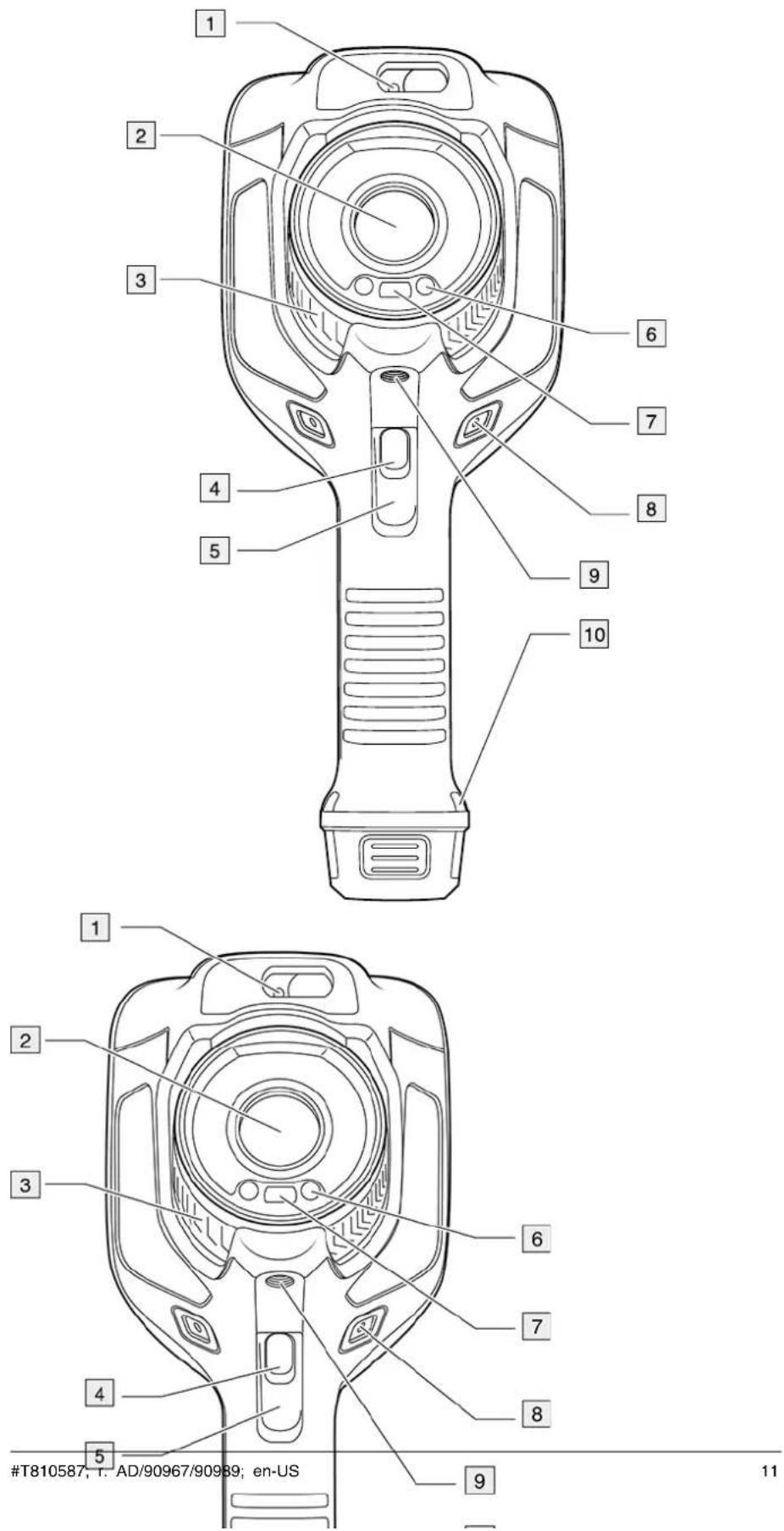
- Laser distance meter!
- Infrared lens.
- Focus ring.
- Autofocus button. ^1
- Trigger.
- Lamp for the digital camera (left and right sides).
- Digital camera.
- Attachment point for the hand strap bracket (left and right sides).
- Tripod mount.
- Attachment point for the hand strap, wrist strap, or lanyard strap (left and right sides).
6.2 View from the rear
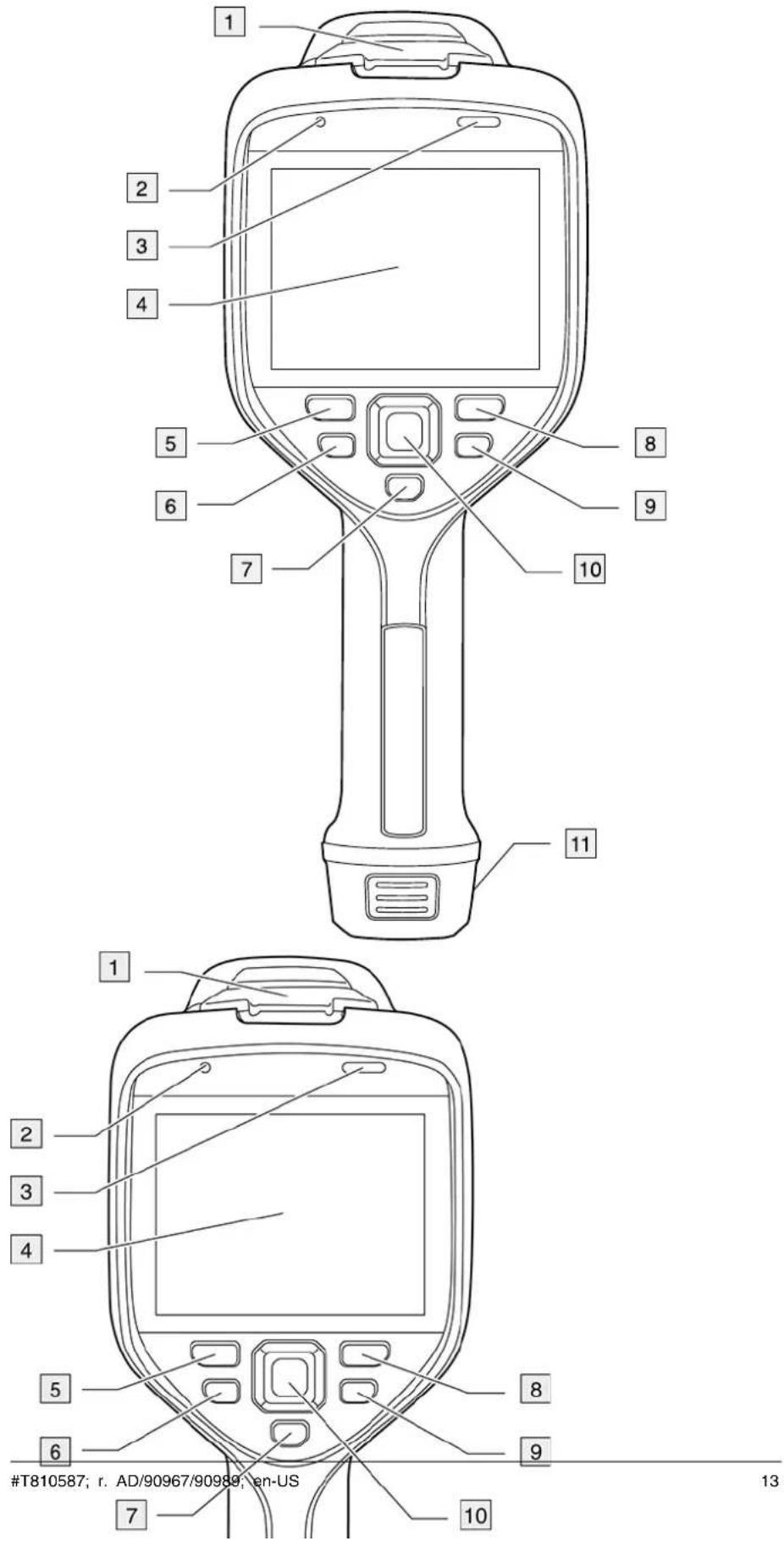
- Cover for the USB connector and memory card slot.
- Microphone.
- Speaker.
- Touch-screen LCD.
- Image archive button.
- Programmable button.
- Button to operate the laser.
- Back button.
- On/off button.
- Navigation pad with center push.
- Battery.
6.3 Laser distance meter and laser pointer
The laser distance meter consists of a laser transmitter and a laser receiver. The laser transmitter also works as a laser pointer.
6.3.1 Laser transmitter and receiver
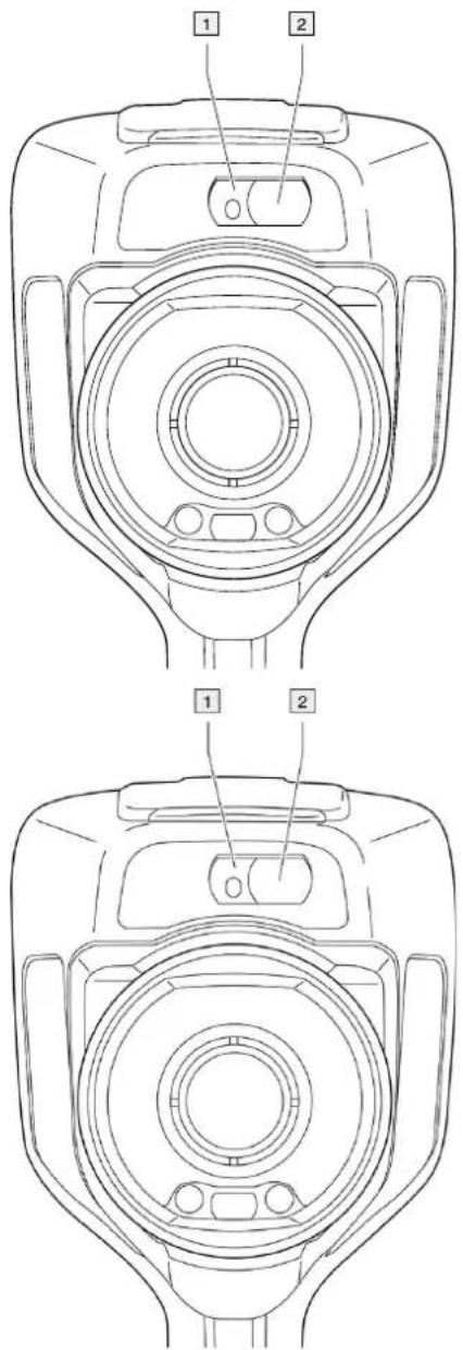
- Laser transmitter.
- Laser receiver. ^2
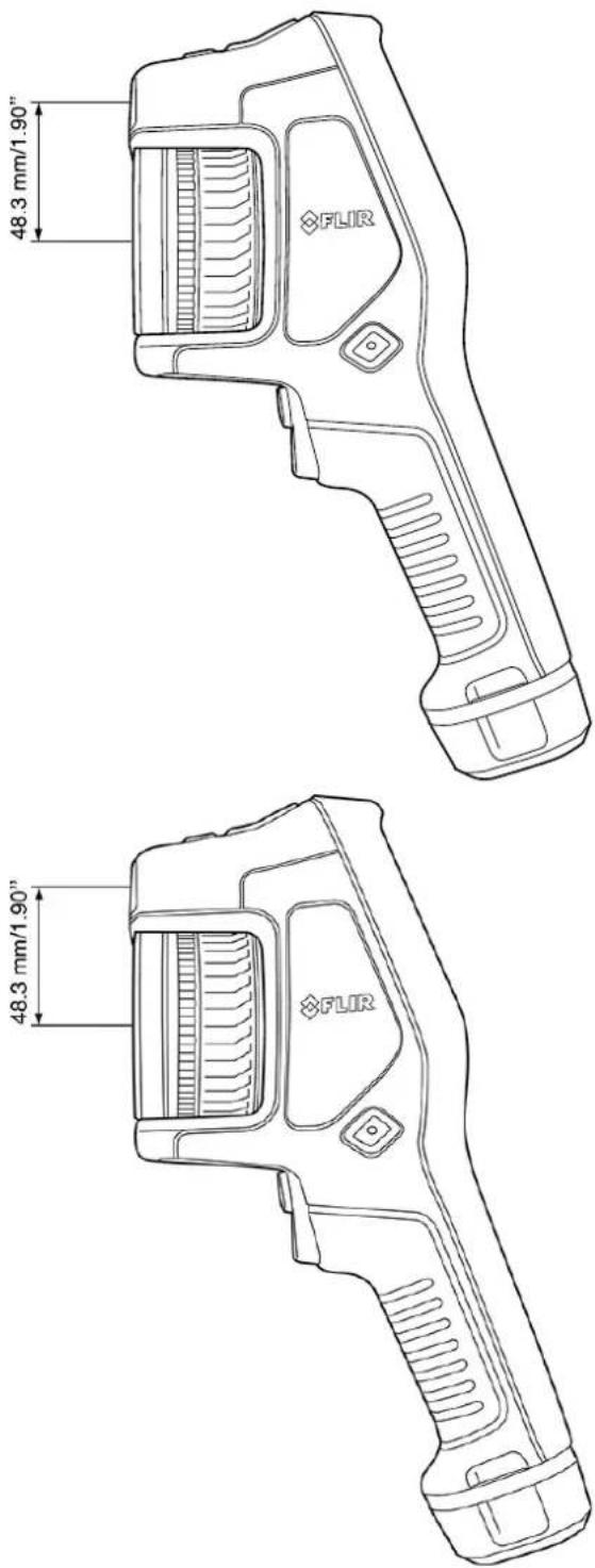
6.3.2 Difference in position
This figure shows the difference in position between the laser transmitter and the optical center of the infrared lens.
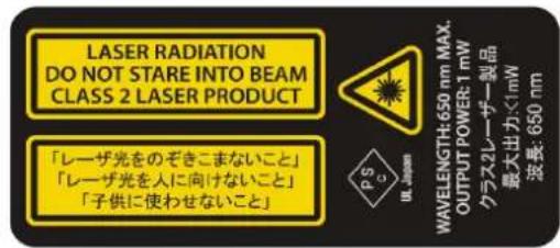
6.3.3 Laser warning label
A laser warning label with the following information is attached to the camera:
6.3.4 Laser rules and regulations
Wavelength: 650 nm. Maximum output power: 1 mW.
This product complies with 21 CFR 1040.10 and 1040.11 except for deviations pursuant to Laser Notice No. 50, dated June 24, 2007.
6.4 Screen elements
6.4.1 General
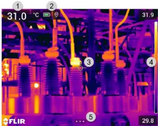
- Result table.
- Status icons.
- Measurement tool (e.g., spotmeter).
- Temperature scale.
- Menu system button.
6.4.2 Menu system
To display the menu system, push the navigation pad or tap the menu system button

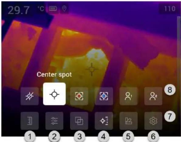
- Temperature scale button.
- Measurement parameters button.
- Image mode button.
- Measurement button.
- Color button.
- Settings button.
- Main menu. ^3
- Submenu.
6.4.3 Status icons and indicators
| Battery levelGreen: above 75%Yellow: up to 75%Red: up to 25%No color: below 15% | |
| The remaining storage capacity of the memory card is below 100 MB. | |
| The GPS is enabled.If the icon is grey, the camera cannot find a GPS signal. | |
| External infrared window compensation is enabled. | |
| The camera is paired with a FLIR Ignite account.The camera is paired, but does not have contact with FLIR Ignite (no inter connection). | |
| A Bluetooth headset is connected. | |
| The laser is on. |
6.4.4 Swipe-down menu
To open the swipe-down menu, place your finger at the top of the screen and swipe down.
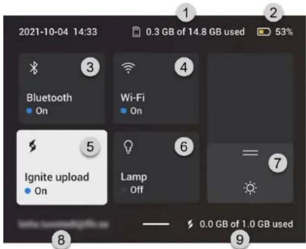
-
Storage status of the memory card.
-
Battery status indicator.
-
Bluetooth button: Touch to enable/disable Bluetooth. Touch and hold to open the Bluetooth settings menu. See also section 21 Pairing Bluetooth devices.
-
Wi-Fi button: Touch to enable/disable Wi-Fi. Touch and hold to open the Wi-Fi settings menu. See also section 20 Configuring Wi-Fi.
-
Ignite upload button: Touch to enable/disable automatic upload of images and videos. See also section 9.5 Automatic upload.
Note If the camera is not paired with a FLIR Ignite account, you will be prompted to sign in to FLIR Ignite before you can enable automatic upload.
- Lamp button: Touch to turn on/off the camera lamp.
Note Before you can turn on the camera lamp, you need to enable the lamp. Select
(Settings) > Device settings > Lamp & laser > Enable lamp & laser or Enable lamp & laser + Use lamp as flash.
-
Screen brightness slider: Use to control the brightness of the screen.
-
The FLIR Ignite user account that the camera is paired with. For more information, see section 9.4 Pairing with FLIR Ignite.
-
Storage status of the FLIR Ignite account.
6.4.5 Image overlay information
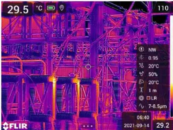
The image information consists of items such as the date, emissivity, and atmospheric temperature. All image information is saved in the image file and can be viewed in the image archive. You can also choose to display selected items as image overlay information. All image overlay information displayed on the live image will also be displayed on saved images. For more information, see sections section 23.6 Device settings and 11.8 Hiding all overlay.
6.5 Navigating the menu system
You can navigate the menu system in two ways:
- Using your finger or a stylus pen specially designed for capacitive touch usage.
• Using the navigation pad and the back button.
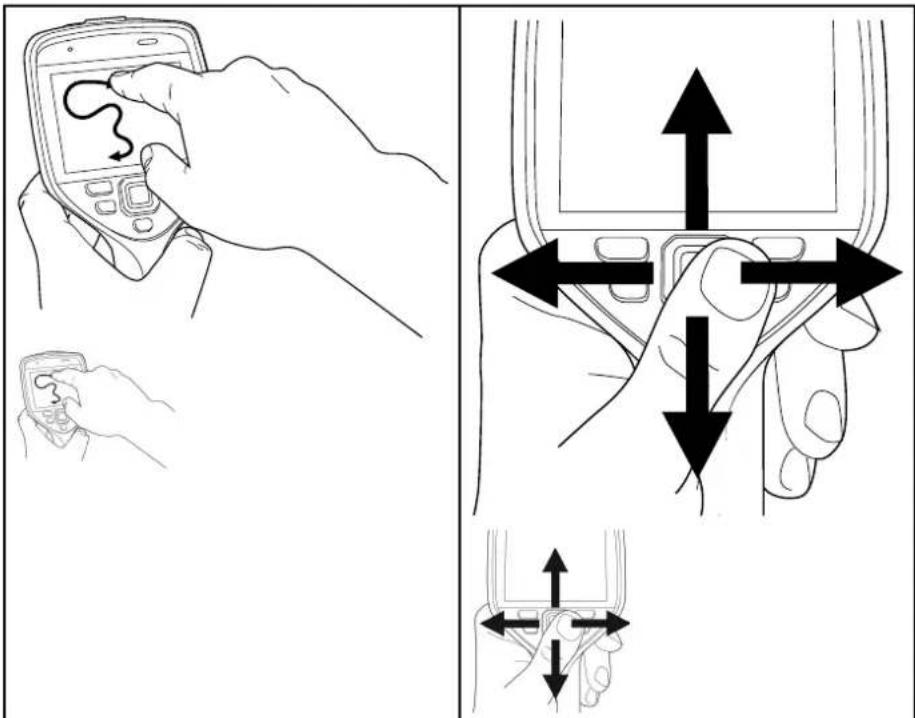
6.5.1 Navigating using the navigation pad
You navigate the menu system by using the navigation pad and the back button:
- To display the menu system, push the center of the navigation pad.
- To navigate in menus, submenus, and dialog boxes, and to change values in dialog boxes, push the navigation pad up/down or left/right.
- To confirm changes and settings in menus and dialog boxes, push the center of the navigation pad.
- To leave dialog boxes and to go back in the menu system, push the back button
7
Handling the camera
7.1 Charging the battery
7.1.1 General
- Before starting the camera for the first time, charge the battery for 2 hours using the stand-alone battery charger.
- Select a mains socket that is near the equipment and easily accessible.
7.1.2 Using the stand-alone battery charger to charge the battery
- Put one or two batteries in the battery charger.
- Connect the power supply cable plug to the connector on the battery charger.
- Connect the power supply mains-electricity plug to a mains socket.
- When the white LED on the battery charger glows continuously, the batteries are fully charged.
- It is good practice to disconnect the stand-alone battery charger from the mains socket when the batteries are fully charged.
7.1.2.1 Stand-alone battery charger LED indicator
| Type of signal Explanation | |
| The white LED flashes. The battery is being charged. | |
| The white LED glows continuously. The battery is fully charged. | |
7.1.3 Using the USB battery charger to charge the battery
- Put the battery into the battery compartment of the camera.
- Connect the USB battery charger to a mains socket.
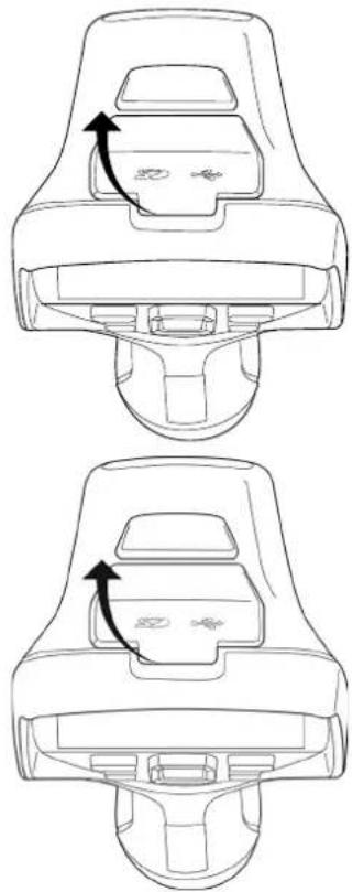
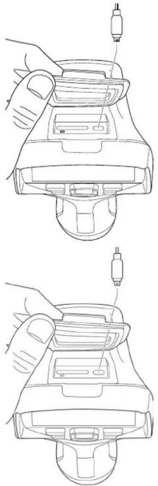
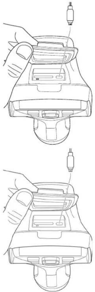
- Fold up the rubber cover at the top of the camera.
natural_image
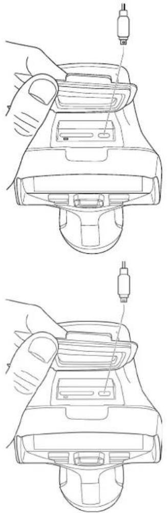
Technical line drawing of a mechanical component with two views showing internal components and directional arrows (no text or symbols)- Connect the USB connector of the USB battery charger to the USB-C connector in the connector bay of the camera.
natural_image
Line drawings of a handheld device with a hand adjusting its top panel (no text or symbols present)-
To check the status of the battery charging, do one of the following:
-
If the camera is turned on: Place your finger at the top of the screen and swipe down. The battery status is displayed on the swipe-down menu.
-
If the camera is turned off: The battery charging indicator is displayed on the screen.
-
It is good practice to disconnect the USB battery charger from the mains socket when the battery is fully charged.
7.1.4 Charging the battery using a USB cable connected to a computer
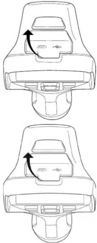
- Fold up the rubber cover at the top of the camera.
natural_image
Technical line drawing of a car seatbelt device with two views showing internal components and directional arrows (no text or symbols)- Connect a USB cable to the USB-C connector in the connector bay. Connect the other end of the USB cable to the computer.
natural_image
Line drawings of a device with a hand adjusting its top panel (no text or symbols present)Note
- To charge the camera, the computer must be turned on.
- Charging the camera using a USB cable connected to a computer takes considerably longer than using the USB battery charger or the stand-alone battery charger.
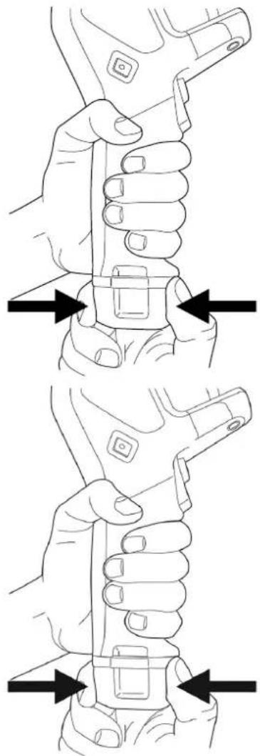
7.2 Removing the battery
-
Turn off the camera.
-
Remove the battery from the camera.
natural_image
Line drawings of a hand holding a wrench, showing two different grip positions (no text or symbols present)7.3 Turning on and turning off the camera
• To turn on the camera, push the on/off button.
• To turn off the camera, push and hold the on/off button for more than 0.5 second.
Note Do not remove the battery to turn off the camera.
7.4 Adjusting the thermal camera focus
It is very important to adjust the focus correctly. Incorrect focus adjustment affects how the image modes work. It also affects the temperature measurement.
You can adjust the camera focus by rotating the focus ring or by pushing the autofocus button. The camera can also be set up to perform continuous autofocusing.
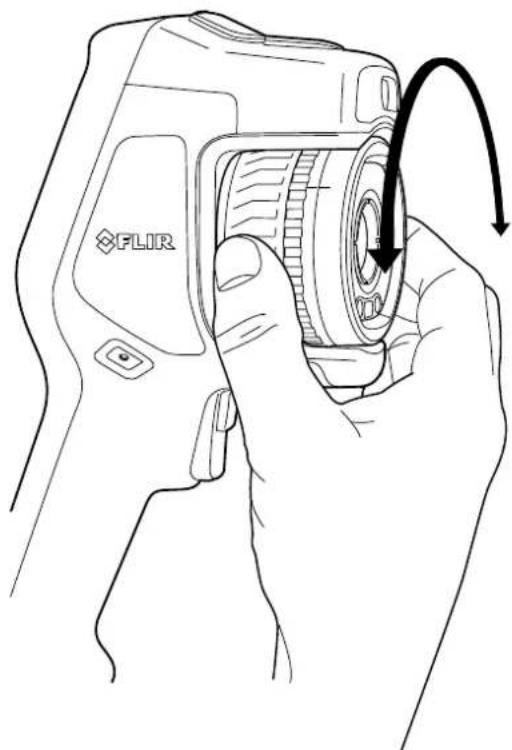
7.4.1 Manual focus
To adjust the focus manually, rotate the focus ring.
natural_image
Line drawing of a hand holding a FLIR digital camera with an arrow indicating rotation (no text or symbols on the device itself)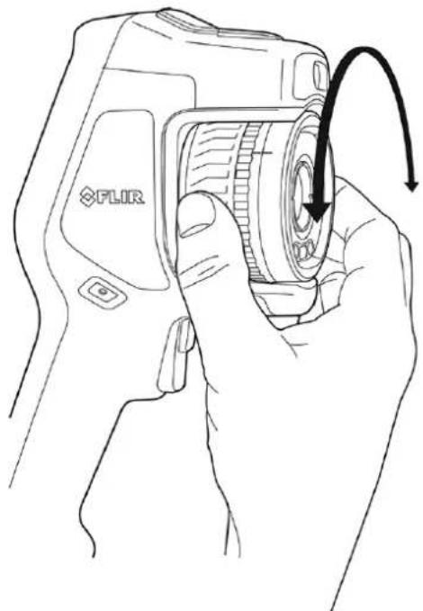
natural_image
Line drawing of a hand holding a digital camera with an arrow indicating rotation (no text or symbols present)Note Do not touch the lens surface when you adjust the focus. If this happens, clean the lens according to the instructions in 24.2 Infrared lens.
7.4.2 Autofocus
To autofocus the camera, push the Autofocus button.
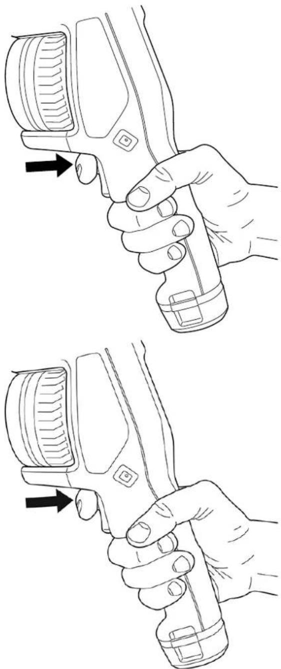
natural_image
Line drawings of a hand holding a handheld device, showing two different states of grip and adjustment (no text or symbols present)Note
- You can also assign the autofocus function to the programmable button. For more information, see section 7.9 Programmable button.
- Autofocus is not supported by all camera models.
7.4.2.1 Autofocus method
When autofocusing, the camera can use one of the following focus methods:
- Contrast: The focus is based on maximizing the image contrast.
- Laser: The focus is based on a laser distance measurement. The laser is used when the camera is autofocusing.
The focus method is configured by a setting. Select ⚙️ (Settings) > Device settings > Focus > Auto focus and then select Contrast or Laser.

WARNING
When the camera is set to autofocusing with the laser method, do not point the camera at the face of a person when you use the autofocus function. The laser beam can cause eye irritation.
7.4.3 Continuous autofocus
The camera can be set up to perform continuous autofocusing.
When the continuous autofocus function is enabled, the camera bases the focus adjustments on continuous laser distance measurements. The laser is continuously on.
To enable or disable continuous autofocus, select (Settings) > Device settings > Focus > Continuous autofocus > On or Off.

WARNING
Do not point the camera at the face of a person when the continuous autofocus function is on. The camera uses laser distance measurements (that are continuous) for the focus adjustments. The laser beam can cause eye irritation.
Note
- Before you can enable continuous autofocus, you need to enable the laser and select laser as focus method. See section 7.4.2.1 Autofocus method.
- When continuous autofocus is enabled, it is not possible to manually adjust the focus by rotating the focus ring.
- You can also assign the continuous autofocus function to the programmable button. For more information, see section 7.9 Programmable button.
- Continuous autofocus is not supported by all camera models.
7.5 Operating the laser distance meter
7.5.1 General
The laser distance meter consists of a laser transmitter and a laser receiver. The laser distance meter determines the distance to a target by measuring the time it takes for a laser pulse to reach the target and return to the laser receiver. This time is converted to a distance, which is displayed on the screen.
The laser transmitter also works as a laser pointer. When the laser is on, you will see a laser dot approximately at the target.

WARNING
Do not look directly into the laser beam. The laser beam can cause eye irritation.
Note
- The laser is enabled by a setting. Select (Settings) > Device settings > Lamp & laser > Enable lamp & laser.
- The symbol ⚠ is displayed on the screen when the laser is on.
- The camera can be configured to automatically measure the distance when an image is saved. Select (Settings) > Save options & storage > Measure distance. With this setting, the Object distance parameter (see section 13.5 Changing the measurement parameters) in the image data is automatically updated with the measured distance when an image is saved. (There is no effect on the Object distance setting live mode.)
- If the target reflection is low or if the target is angled from the laser beam, there may be no return signal, and the distance cannot be measured.
- The laser distance meter is not supported by all camera models.
- The laser distance meter may not be enabled in all markets.
7.5.2 Procedure
To operate the laser, do the following:
- To turn on the laser, push and hold the laser button The distance to the target is displayed on the screen.
- To turn off the laser, release the laser button.
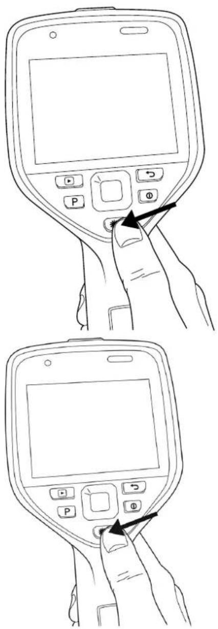
7.6 Measuring areas
7.6.1 General
Note The availability of this feature is dependent on the camera model.
The distance measured by the laser distance meter can be used as the basis for area calculations. A typical application is to estimate the size of a damp stain on a wall.
To measure the area of a surface, you need to lay out a box or circle measurement tool on the screen. The camera calculates the area of the surface enclosed by the box or circle tool. The calculation is an estimate of the surface area, based on the measured distance to the target.
When the laser distance meter is on, you will see a laser dot approximately at the target. The laser distance meter measures the distance to that target. The camera assumes that this distance is valid for the entire box or circle tool.
For successful area measurements, keep the following in mind:
- Make sure that the box or circle tool is in the center of the image.
- Adjust the size of the box or circle tool to the size of the target.
- Hold the camera perpendicular to the target.
- Avoid targets with many details at different distances from the camera.
7.6.2 Procedure
Note This procedure assumes that you have enabled the laser. Select (Settings) > Device settings > Lamp & laser > Enable lamp & laser.
Follow this procedure:
- Add a box or circle measurement tool, see section 13.2 Adding/removing measurement tools.
- Set the camera to measure and display the area of the box or circle, see section 13.6 Displaying values in the result table.
- Make sure that the box or circle tool is in the center of the image, see section 13.4 Moving and resizing a measurement tool.
- Adjust the size of the box or circle tool to the size of the target, see section 13.4 Moving and resizing a measurement tool.
- Hold the camera perpendicular to the target. Push and hold the laser button
- The calculated area is displayed in the result table.
7.7 Connecting external devices and storage media
You can connect the following external devices and media to the camera:
- An SD memory card.
- A computer to move image and video files to and from the camera, using a USB-C to USB-A or a USB-C to USB-C cable.
- A video monitor or projector, using a USB-C to HDMI adapter.
• A USB battery charger.
Note Empty or use a memory card that has not previously been used in another type of camera. The cameras may organize files differently on the memory card. There is therefore a risk of losing data if the same memory card is used in different types of cameras.
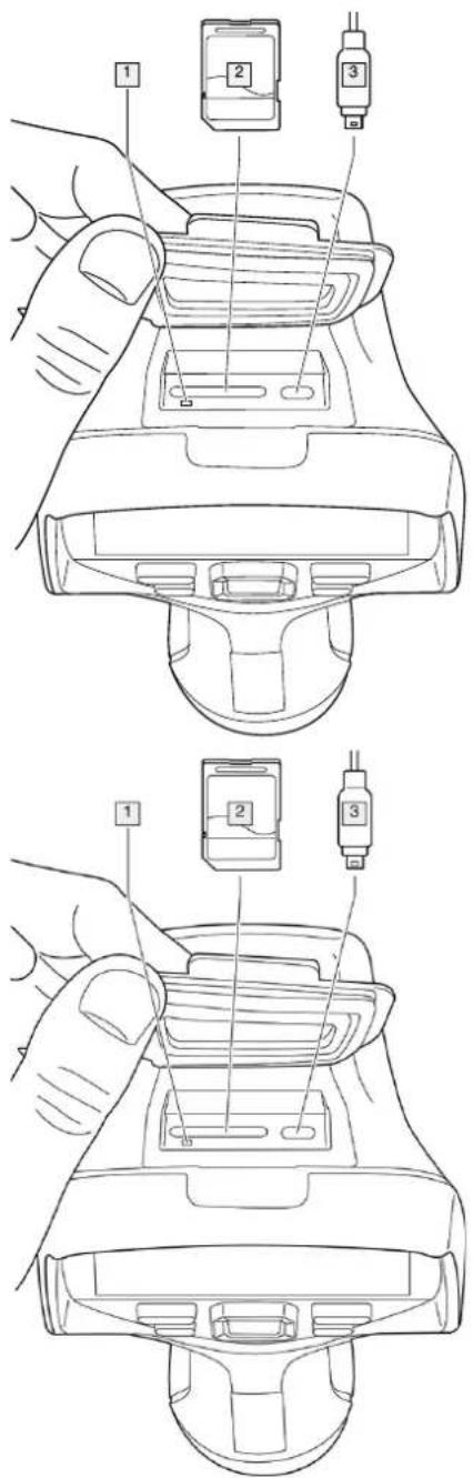
- LED indicator showing that the memory card is busy.
Note
- Do not eject the memory card when this LED is flashing.
-
Do not connect the camera to a computer when this LED is flashing.
-
SD memory card.
- USB-C cable.
7.8 Moving files to a computer
When you save an image or video clip in the image archive of the camera, the file is stored on the memory card.
You can connect the camera to a computer, using a USB-C to USB-A or a USB-C to USB-C cable. Once connected, you can move the image and video files from the memory card to the computer.
To move files to a computer via USB cable, do the following:
- Fold up the rubber cover at the top of the camera.
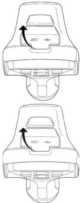
natural_image
Technical line drawing of a car seatbelt device with two views showing internal components and directional arrows (no text or symbols)- Connect a USB cable to the USB-C connector in the connector bay. Connect the other end of the USB cable to the computer.
natural_image
Line drawings of a device with a hand adjusting its top panel (no text or symbols present)-
Turn on the camera.
-
Do one of the following:
-
Move the files to the computer using a drag-and-drop operation.
Note Moving a file using a drag-and-drop operation does not delete the file in the camera. - Import the images into a FLIR Thermography software.
7.8.1 Related topics
You can also set up the camera to upload images for storage online, see section 9 Cloud connectivity, page 63.
7.9 Programmable button
natural_image
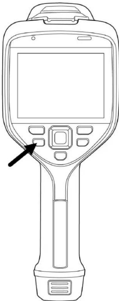
Line drawing of a handheld medical or scientific device with a control panel and an arrow pointing to the left side (no text or symbols present)You can assign different functions to the programmable button. You can, for example, use the programmable button to easily switch between two settings you use often. You can also choose to define two different setups for saving and previewing: the ordinary setup for the trigger (which is defined by the Save options and storage settings, see section 23.5 Save options & storage) and another setup for the programmable button.
To assign a function to the programmable button, do the following:
- Push and hold the programmable button. This displays the Programmable button menu.
- Push the navigation pad up/down to select one of the functions. Push the center of the navigation pad to confirm.
7.9.1 Programmable button options
Available options for the programmable buttons:
- No action: This is the default setting. Nothing will happen when you push the button.
- Switch Auto <> Manual temperature scale: Switch between automatic or manual image adjustment mode. For more information, see section 11.3 Adjusting the infrared image.
- Autofocus 4: One-shot autofocus of the infrared camera.
- Continuous autofocus: Switch between the enabled/disabled continuous autofocus functions.
- Hide image overlay graphics: Switch between hide/show all overlay graphics and image overlay information. For more information, see section 11.8 Hiding all overlay.
- Calibrate: Perform a manual NUC. For more information, see section 11.7 Performing a non-uniformity correction (NUC).
- Auto-adjust the manual temperature scale: Perform an automatic adjustment of the image while remaining in manual image adjustment mode.
- Switch Thermal <> Digital camera: Switch between the image modes Thermal and Digital camera. For more information, see section 12 Working with image modes.
- Switch Thermal <> Thermal MSX: Switch between the image modes Thermal and Thermal MSX. For more information, see section 12 Working with image modes.
- Switch 1x zoom <> Max zoom: Switch between the digital zoom factor of 1x and r imum zoom.
- Switch camera flash On <> Off: Switch between the enabled/disabled camera flash functions. For more information, see section 7.10 Using the camera lamp as a fla:
Note The flash function will not be activated if the setting Lamp & laser is set to the option Disable all. For more information, see section 23.6 Device settings. - Switch single shot <> Video: Switch between the recording modes Single shot and Video.
- Switch between two latest palettes: Switch between the two last-used color palettes. For more information, see section 11.5 Changing the color palettes.
- Switch temperature range: Cycle through the camera temperature ranges. For more information, see section 23.4 Camera temperature range.
- Switch screen rotation On <> Off: Switch between enabled/disabled screen rotation.
- Save: Save an image.
- Save + Prompt for note: Save an image and display the note annotation tool.
- Save + Prompt for table: Save an image and display the table annotation tool.
- Save + Prompt for voice annotation: Save an image and display the voice annotatic tool.
- Save + Prompt for sketch: Save an image and display the sketch annotation tool.
- Save + Select annotation from menu: Save an image and display the annotation to menu.
- Preview: Display a preview image.
- Preview + Prompt for note: Display a preview image and the note annotation tool.
- Preview + Prompt for table: Display a preview image and the table annotation tool.
- Preview + Prompt for voice annotation: Display a preview image and the voice annotation tool.
- Preview + Prompt for sketch: Display a preview image and the sketch annotation to
- Preview + Select annotation from menu: Display a preview image and the annotatio tool menu.
7.10 Using the camera lamp as a flash
The camera lamp can be used as a flash for the digital camera. When the flash function is enabled, the camera lamp will flash when an image is saved by pulling the trigger.
You can also turn on the camera lamp to use it as a flashlight.
Follow this procedure:
- Push the navigation pad to display the menu system.

- Select ⚙️ (Settings) and push the navigation pad. This displays the Settings menu.
- Use the navigation pad to select Device settings > Lamp & laser.
-
To use the camera lamp as a flash, do one of the following:
-
To enable the camera lamp function, select Enable lamp & laser and push the nigation pad. To turn on/off the camera lamp, use the swipe-down menu, see section 6.4.4 Swipe-down menu.
- To enable the flash function, select Enable lamp & laser + Use lamp as flash push the navigation pad.
- To disable the camera lamp and flash functions, select Disable all and push the navigation pad.
Note You can also assign the function Switch camera flash On <> Off to the programmable button. For more information, see section 7.9 Programmable button.
7.11 Hand strap
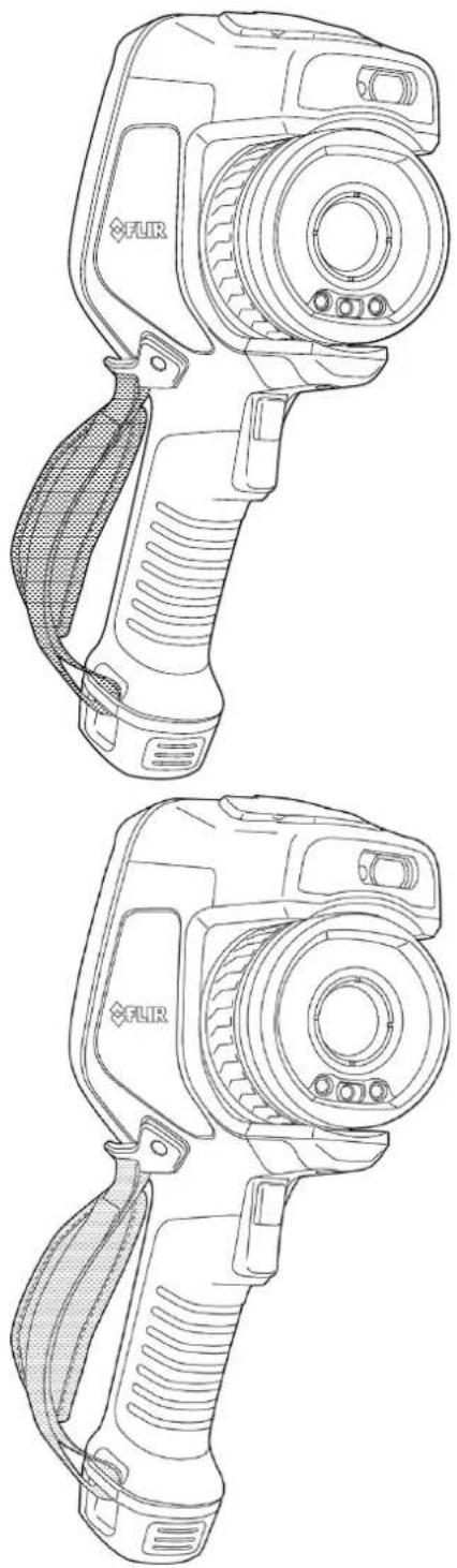
The upper part of the hand strap is attached to the camera by a bracket. There is one bracket for the left side and one for the right side of the camera.
The lower part of the hand strap is threaded through the attachment point at the base of the camera.
natural_image
Line drawings of FLIR thermosKhodors (no text or symbols)7.11.1 Mounting the hand strap
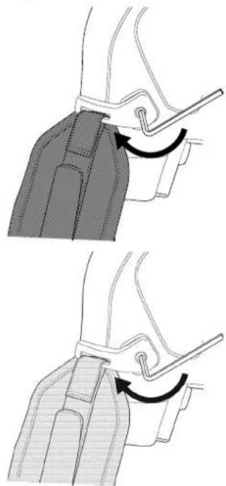
- Fit the upper part of the hand strap into the bracket.

natural_image
Four-step illustration showing a hand holding a zipper, with arrows indicating the process (no text or symbols present)- Fit the bracket in place on the camera and tighten the screw with the supplied Torx key.
natural_image
Technical illustration showing two steps of a mechanical clamp or bracket assembly (no text or symbols present)- Thread the loose strap through the attachment point at the base of the camera. Secure the strap with the hook-and-loop fastener.
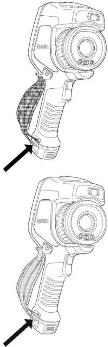
natural_image
Technical line drawings of a two-part device with labeled parts, showing top and side views (no text or symbols present)7.12 Lanyard strap
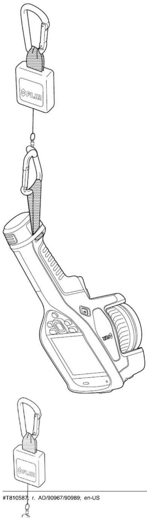
To mount the lanyard strap, do the following:
- Remove the camera battery.
- Starting with the FLIR logo part, thread the lanyard strap through the attachment point at the base of the camera.
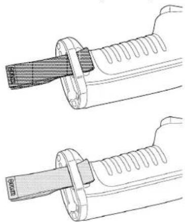
natural_image
Illustration of two hands performing a mechanical manipulation or repair operation on a cylindrical object (no text or symbols present)- Pull the entire lanyard strap through the attachment point until it stops.
natural_image
Technical line drawing of a mechanical component with two views (top and side), no text or symbols present.7.13 Wrist strap
The wrist strap can also be used to attach a carabiner to the camera.
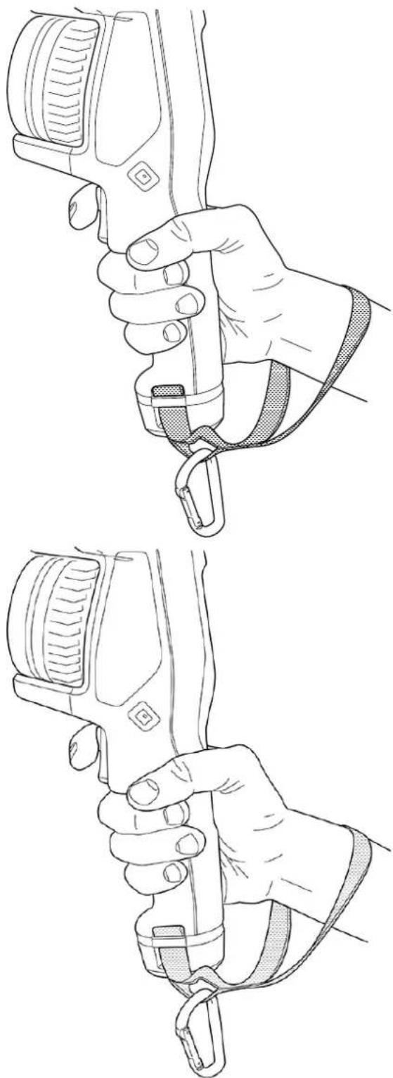
natural_image
Line drawings of a hand holding a camera with a strap, showing two different grip configurations (no text or symbols present)To mount the wrist strap, do the following:
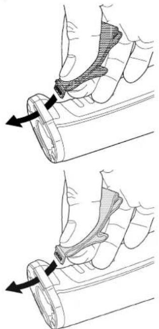
1. Remove the camera battery.
- Fold the wrist strap. Make sure that the part with the FLIR logo faces away from the bend.
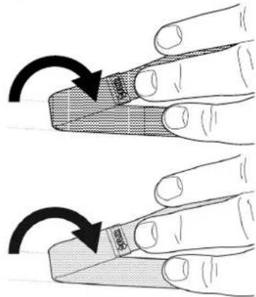
- Thread the bent wrist strap through the attachment point at the base of the camera.
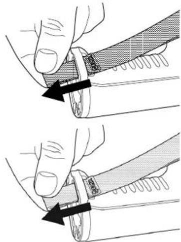
natural_image
Illustration showing two hands holding a tool, with arrows indicating movement or force direction (no text or symbols present)- Pull the entire wrist strap through the attachment point until it stops.
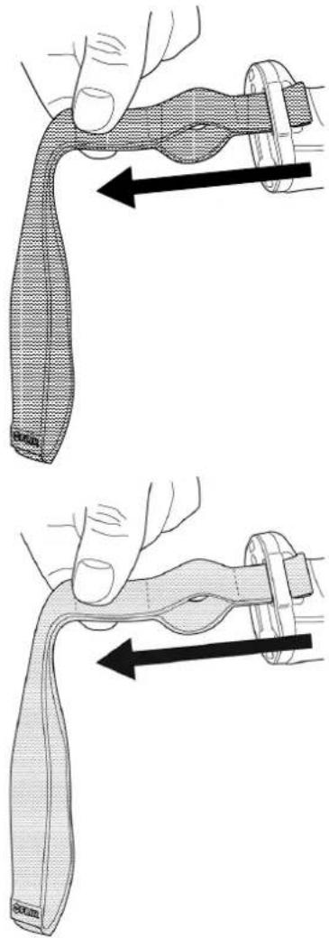
natural_image
Illustration of a hand holding a knuckle and a wrist strap, showing two different movement directions (no text or symbols)7.14 Front protection
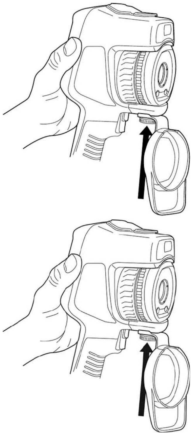
To protect the camera lens and the laser distance meter, you can attach the front protection by using the supplied fastening device.
natural_image
Line drawings of a hand holding a camera with an arrow indicating the adjustment point (no text or symbols present)7.15 Changing camera lenses
Applicability: Camera models with an exchangeable lens.
Note If the new lens has not been used with the camera before, the lens-camera combination must be calibrated after the lens has been mounted. See section 7.16 Calibrating the lens-camera combination for information on how to do this.
Note Do not touch the lens surface when you change lenses. If this happens, clean the lens according to the instructions in 24.2 Infrared lens.
Follow this procedure:
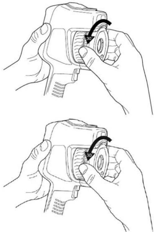
- Take a firm grip around the inner ring of the lens. Rotate the inner ring 30^ counterclockwise until it stops.
natural_image
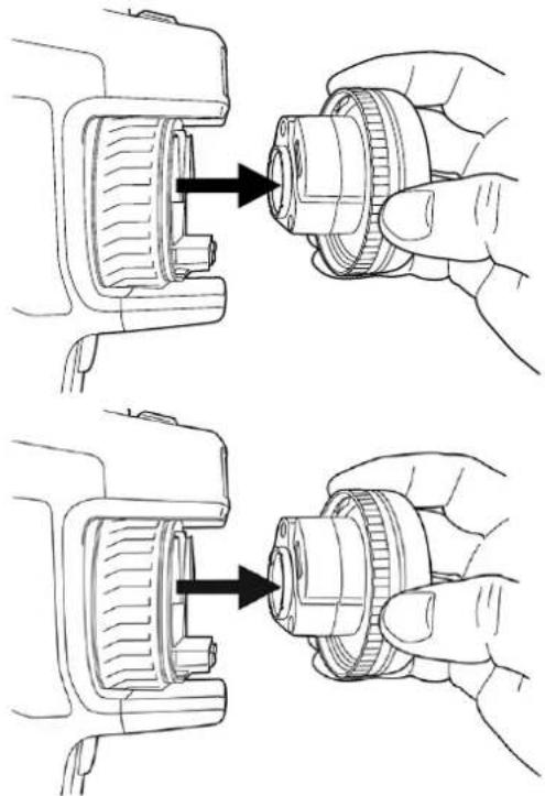
Two-step line drawings of hands adjusting a camera lens (no text or symbols present)- Carefully pull out the lens.
natural_image
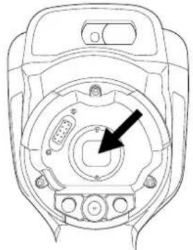
Technical line drawing showing hands adjusting a mechanical component with arrows indicating assembly (no text or symbols present)- The infrared detector is now fully exposed. Do not touch this surface. If you see dust on the detector, follow the instructions in 24.3 Infrared detector.
natural_image
Technical line drawing of a mechanical component with no visible text or symbols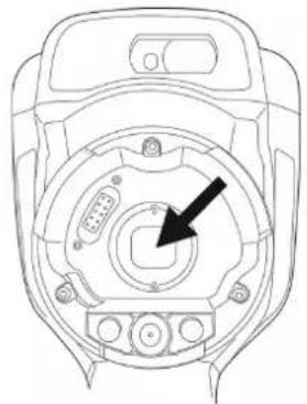
natural_image
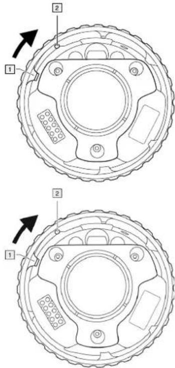
Technical line drawing of a mechanical component with no visible text or symbols- Make sure that the inner ring of the camera lens is fully in its open position.
- Correct: The tooth (1) is in its end position at the black stop pin (2).
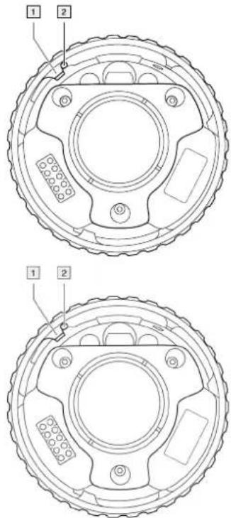
- Wrong: You must rotate the inner ring until the tooth (1) reaches the black stop pin (2).
- Carefully push the lens into position.
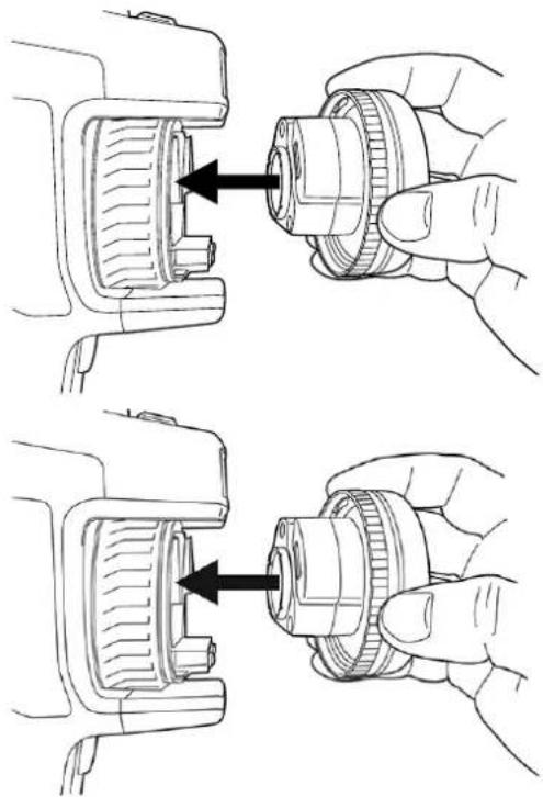
natural_image
Technical illustration showing two hands adjusting a mechanical component with arrows indicating assembly or adjustment (no text or symbols present)- Rotate the inner ring of the lens 30^ clockwise. The lens makes a click when it locks in place.
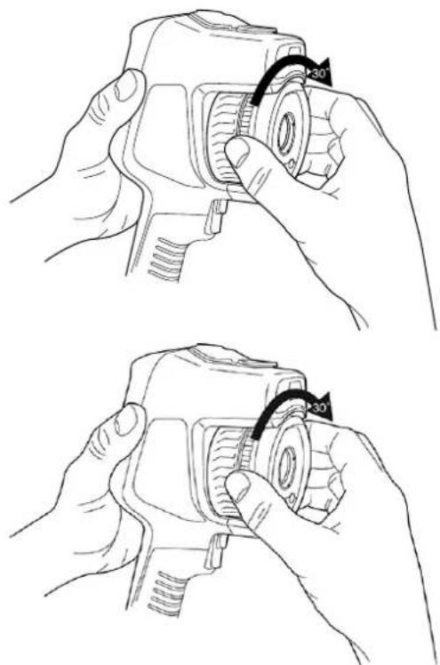
natural_image
Two-step line drawings of hands adjusting a camera lens, showing the process with 30° rotation arrows (no text or symbols present)- Make sure that the two index marks are aligned, indicating that the lens is locked in place.
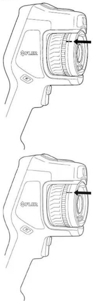
7.16 Calibrating the lens-camera combination
Applicability: Camera models with an exchangeable lens.
7.16.1 Introduction
Before a new lens can be used with the camera, the lens-camera combination must be calibrated.
This is a process that previously had to be performed by a FLIR service department, but for the FLIR Exx series the calibration can be performed by the user. This feature is called AutoCal. The AutoCal procedure requires a calibration target, which is included in the lens package.
Note For lenses that ship with the camera, the lens-camera combination is factory calibrated.
7.16.2 AutoCal procedure
- Dip the calibration target in water for 1 second and let the excess drip off.
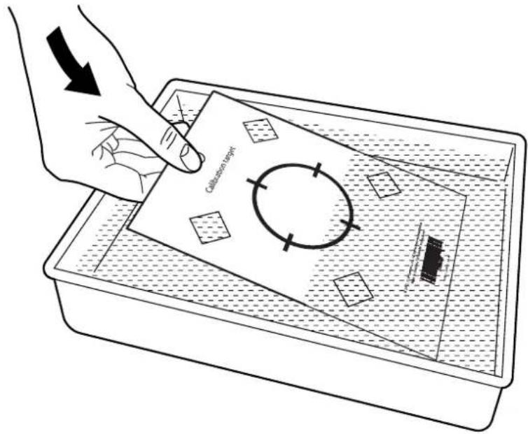
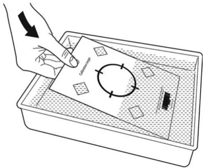
- Tape or hang the calibration target on a wall.
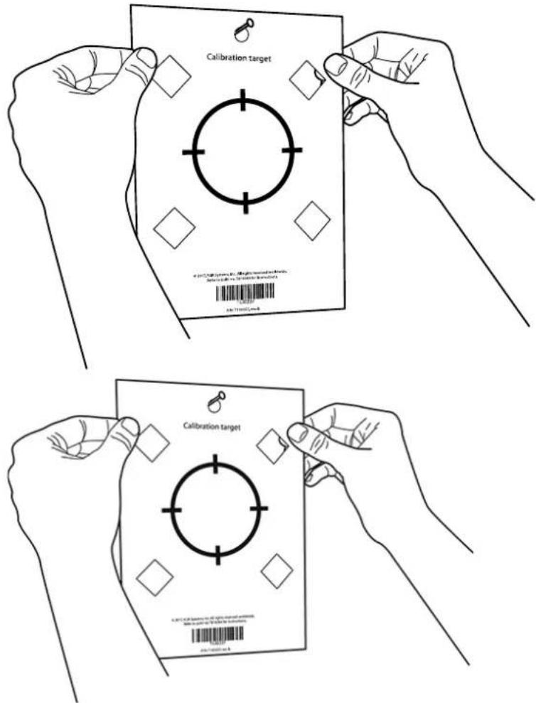
-
Mount the new lens on the camera according to the procedure in section 7.15 Changing camera lenses. When the lens is mounted, the calibration wizard starts automatically.
-
From a distance of 2 m (6.6 ft.), aim the camera toward the crosshair, using the laser pointer. The camera will take a picture automatically.
Note Make sure the camera's optical path is perpendicular to the calibration target. See the image below.
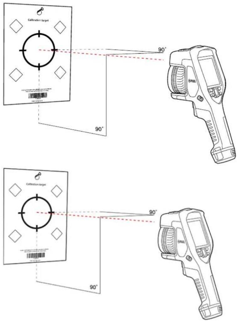
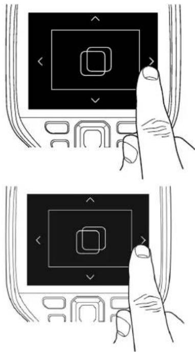
- In the camera, align the thermal and visual images (indicated by the two squares in the image below), using the touchscreen arrows. The lens-camera combination is now calibrated.
natural_image
Illustration of a hand interacting with a touchscreen device, showing two states of action (no text or symbols present)To repeat the procedure at a later time, go to Settings > Device settings > Camera information > Calibration > Calibrate lens...
7.17 Calibrating the compass
It is recommended that the compass is calibrated every time you move the camera to a new location.
Follow this procedure:
- Push the navigation pad to display the menu system.
- Select ⚙️ (Settings) and push the navigation pad. This displays the Settings menu.
- Use the navigation pad to select Device settings > Geolocation > Compass.
- Make sure the compass is enabled by toggling the switch.
- Select Calibrate compass and push the navigation pad. Follow the on-screen instructions.
Note You must rotate the camera slowly.
8.1 About image files
8.1.1 General
When you save an image, the camera saves an image file that includes all thermal and visual information. This means that you can open an image file at a later time and, for example, select another image mode, apply color alarms, and add measurement tools.
The image *.jpg file is fully radiometric and saved lossless, which enables full post-processing in image analysis and reporting software from FLIR Systems. There is also a regular *.jpg component (lossy) for convenient viewing in non-FLIR Systems software (e.g., Microsoft Explorer).
Note
- The camera can also be configured to save an extra low-resolution visual image as a separate file. This can be convenient if you are not using a post-processing software.
Select ⚙️ (Settings) > Save options & storage > Photo as separate JPEG = On.
- When the Digital camera image mode is selected, a high-resolution digital image is stored when an image is saved. However, no thermal information is stored. For more information, see section 12 Working with image modes.
- You can choose to turn off the digital camera. This can, for example, be required in restricted areas and in confidential (e.g., doctor/patient) situations. Select(Settings) > Save options & storage > Digital camera = Off. When the digital camera is off, features that require visual information, such as the images modes Thermal MSX and Picture in picture, are disabled.
8.1.2 File-naming convention
The default naming convention for image files is FLIRxxxx.jpg, where xxxx is a unique counter.
It is also possible to save images with a date prefix added to the filename. However, these files may not automatically be detected by third-party applications. For more information, see the setting File naming format in section 23.5 Save options & storage.
8.1.3 Storage capacity
When you save an image, the camera stores the image file on the memory card.
The size of an image file (with no annotations) is typically less than 1000 kB. Thus, the capacity of a 8 GB memory card is approximately 8000 images.
Note Empty or use a memory card that has not previously been used in another type of camera. The cameras may organize files differently on the memory card. There is therefore a risk of losing data if the same memory card is used in different types of cameras.
8.1.4 About UltraMax
Note The availability of this feature is dependent on the camera model.
UltraMax is an image enhancement feature that increases the image resolution and lowers the noise, making small objects easier to see and measure. An UltraMax image is twice as wide and high as an ordinary image.
When an UltraMax image is captured by the camera, several ordinary images are saved within the same file. Capturing all the images can take up to 1 second. To fully utilize UltraMax, the images need to be slightly different, which can be accomplished by a minute movement of the camera. You should hold the camera firmly in your hands (do not put it on a tripod), which will make these images vary just a little during the capture. Correct focus, a high-contrast scene, and a non-moving target are other conditions that help to achieve a good-quality UltraMax image.
Some FLIR Thermography software has the ability to process UltraMax images. Other FLIR software will treat the image as a regular image.
To configure the camera for UltraMax, select (Settings) > Save options & storage > Image resolution = UltraMax.
8.2 Saving an image
When you save an image, the camera stores the image file in the camera memory.
Note You can also set up the camera to upload images for storage online, see section 9 Cloud connectivity.
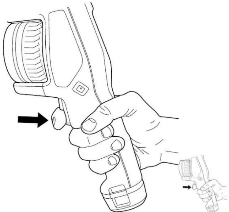
To save an image, pull the trigger.
natural_image
Line drawing of a hand holding a handheld device with a tool, showing motion arrows (no text or symbols)Note Depending on the settings in ⚙️ (Settings) > Save options & storage, the following may also happen:
- A preview image is displayed before the image is saved.
- An annotation tool or the annotation menu is displayed when the image has been saved.
8.3 Previewing an image
You can preview an image before you save it. This enables you to see if the image contains the information you want before you save it. You can also adjust and edit the image
Note The camera must be configured to display a preview image before saving. Select
(Settings) > Save options & storage > Preview image before saving = On.
To preview an image, do the following:
- To preview an image, pull the trigger. This displays the preview.
-
Manual image adjustment mode is now active. For image adjustment instructions, see section 11.3 Adjusting the infrared image.
-
To edit the image, push the navigation pad. This displays a context menu. For editing instructions, see section 8.5 Editing a saved image.
-
Do one of the following:
- To save the image, pull the trigger.
- To exit preview mode without saving, push the back button.
8.4 Opening a saved image
When you save an image, the image file is stored on the memory card. To display the image again, open it from the image archive (Gallery).
To open a saved image, do the following:
- Push the image archive button. This displays the Gallery with one or more folders.
- Select a folder and push the navigation pad.
- Select the image you want to view and push the navigation pad.
- Do one or more of the following:
- To view the previous/next image, push the navigation pad left/right.
- To display a toolbar at the top of the screen, push the navigation pad. Do one or more of the following:
To switch between an infrared image and a visual image, select the icon and push the navigation pad.
To edit the image, delete the image, display information, or add annotations, select the : icon and push the navigation pad. This displays a menu to the right.
- To return to the folder overview, push the back button.
- To return to the live image, push the image archive button.
8.5 Editing a saved image
You can edit a saved image. You can also edit an image in preview mode.
To edit a saved image, do the following:
- Push the image archive button. This displays the Gallery.
- Select a folder and push the navigation pad.
- Select the image you want to edit and push the navigation pad.
- Push the navigation pad to display the top toolbar.
- On the top toolbar, select the icon and push the navigation pad.
- On the right toolbar, select the icon and push the navigation pad. This opens the image in edit mode.
-
Manual image adjustment mode is now active. For image adjustment instructions, see section 11.3 Adjusting the infrared image.
-
Push the navigation pad. This displays a context menu.
-
Select × (Cancel) to exit edit mode.
- Select (Measurement parameters) to change the global parameters.
- Select (Image mode) to change the image mode.
- Select ⚙ (Measurement) to add a measurement tool.
- Select (Color) to change the color palette or set a color alarm.
-
Select ↓ (Save) to save and exit edit mode.
-
To store the edited image online, make a manual upload of the image. See section 9.6 Manual upload.
8.5.1 Related topics
• 11.6 Changing the measurement parameters.
• 12 Working with image modes.
• 13 Working with measurement tools.
• 11.5 Changing the color palettes.
• 14 Working with color alarms and isotherms.
8.6 Displaying the image information
The image information consists of items such as the date, emissivity, and atmospheric temperature. When you save an image, the image information is saved in the image file and can be viewed in the image archive (Gallery).
To display the image information, do the following:
- Push the image archive button ▶. This displays the Gallery.
- Select a folder and push the navigation pad.
- Select an image and push the navigation pad.
- Push the navigation pad to display the top toolbar.
- On the top toolbar, select the icon and push the navigation pad.
- On the right toolbar, select the icon and push the navigation pad. This displays the image information.
8.7 Zooming an image
You can zoom an image by using the camera's digital zoom function. You can do this on live images and on saved images in edit mode.
The digital zoom factor is displayed at the top of the screen.
To digitally zoom an image, do the following:
- Zoom in: Touch the screen with two fingers and spread the fingers apart.
- Zoom out: Touch the screen with two fingers and pinch the fingers together.
8.8 Deleting images
You can delete image files from the memory card. For more information, see sections 10.9 Deleting an image or video file, 10.10 Deleting multiple files, and 10.11 Deleting all files.
8.9 Resetting the image counter
You can reset the numbering of the image filenames.
Note To prevent image files being overwritten, the new counter value will be based on the highest existing filename number in the image archive. To ensure that the counter is reset to 0001, insert an empty memory card before resetting the counter.
Follow this procedure:
- Push the navigation pad to display the menu system.
- Select ⚙️ (Settings) and push the navigation pad. This displays the Settings menu.
- Use the navigation pad to select Device settings > Reset options > Reset image counter....
- Push the navigation pad. This displays a dialog box.
- To reset the counter, select Reset and push the navigation pad.
FLIR Ignite is a cloud storage service for thermal images. Upload images from your camera and your data will be instantly available across all your devices. With FLIR Ignite you can edit images and create basic reports. You can also share images with colleagues and clients and invite team members to work in the same folder and files.
FLIR Ignite also includes a PC-based application called FLIR Ignite Sync that allows you to sync your image library with your computer. This gives you easy access to images when creating reports in FLIR Thermal Studio or other post-processing software.
9.1 Uploading to FLIR Ignite
You can set up the camera to upload images and videos to FLIR Ignite.
If automatic upload is enabled, new images and videos will automatically be uploaded to the FLIR Ignite account. You can also upload images and videos manually from the image archive.
To be able to upload images and videos, you need to connect the camera to the internet and pair the camera with a FLIR Ignite account.
9.2 Connecting to internet
You can connect the camera to the internet via Wi-Fi or Bluetooth.
9.2.1 Connecting to Wi-Fi
You can connect the camera to a Wi-Fi network as part of the initial setup of the camera. You can also connect the camera at any time via the Settings menu.
To connect to Wi-Fi via the Settings menu, do the following:

- Select 🎨 (Settings) > Connections > Wi-Fi > Connect to network.
- To display a list of the available networks, select Available networks.
- Select one of the available networks and push the navigation pad.
Note Password-protected networks are indicated with a padlock icon, and for these you will need to enter a password the first time you connect to the network. After that the camera will connect automatically to the network. To disable the automatic connection, select Forget network.
Note To enable/disable the camera firewall, select Connections > Advanced > Global firewall.
9.2.2 Connecting via Bluetooth
If supported by your mobile phone, you can share the phone's internet connection with the camera via Bluetooth.
Note The Bluetooth protocol is limited in terms of data transfer and best suited for upload of single images. For upload of videos and folders with several images, it is recommended to use Wi-Fi.
To connect the camera to the internet via your mobile phone, do the following:

- Select ⚙️ (Settings) > Connections > Bluetooth.
- Make sure Bluetooth is enabled by toggling the Bluetooth switch.
Note On the mobile phone, you must make sure that Bluetooth is enabled, that the phone is in discovery mode, and that Bluetooth tethering is enabled.
- Select Available devices and push the navigation pad.
- Wait until a list of available Bluetooth devices is displayed.
- Select your mobile phone and begin the pairing procedure.
9.3 Creating a FLIR Ignite account
To create a FLIR Ignite account, go to https://ignite.flir.com and click Sign up.
9.4 Pairing with FLIR Ignite
You can pair the camera as part of the initial setup of the camera. You can also pair the camera at any time via the Settings menu.
To pair the camera via the Settings menu, do the following:
- Make sure the camera is connected to the internet.
- Select ⚙️ (Settings) > FLIR Ignite.
- Start the pairing procedure by selecting Sign in.
- Use a computer or other device with internet access and go to the website displayed on the camera screen.
- On the website, enter the code displayed on the camera screen.
- Sign in to your FLIR Ignite account.
9.5 Automatic upload
You can set up the camera to automatically upload images and videos to your FLIR Ignite account.
When automatic upload is enabled, new images and videos will automatically be uploaded when the camera is connected to the internet and paired with FLIR Ignite.
To enable automatic upload, do the following:
- Make sure the camera is paired with your FLIR Ignite account.
- Select ⚙️ (Settings) > FLIR Ignite.
- Enable/disable automatic upload by toggling the Auto upload switch.
Note You can also enable automatic upload on the swipe-down menu. For more information, see section 6.4.4 Swipe-down menu.
9.6 Manual upload
You can manually upload images, videos, and folders from the image archive when the camera is paired with a FLIR Ignite account and connected to the internet.
You can monitor the upload progress at the top of the image archive.
9.6.1 Uploading an image/video file
- Make sure the camera is connected to the internet.
-
Make sure the camera is paired with a FLIR Ignite account.
-
Push the image archive button
-
Select a folder and then select an image or video.
-
Push the navigation pad to display the top toolbar.
-
On the top toolbar, select the icon.
- On the top toolbar, select the
- On the right toolbar, select the icon.
9.6.2 Uploading multiple files
- Make sure the camera is connected to the internet.
-
Make sure the camera is paired with a FLIR Ignite account.
-
Push the image archive button
-
Select a folder.
- On the top toolbar, select the icon.
- Select the images and videos you want to upload. Selected files are marked with a tick.
- On the right toolbar, select the icon.
9.6.3 Uploading folders
- Make sure the camera is connected to the internet.
- Make sure the camera is paired with a FLIR Ignite account.
- Push the image archive button.
- On the top toolbar, select the icon.
- Select the folders you want to upload. Selected folders are marked with a tick.
- On the right toolbar, select the icon.
9.7 Accessing FLIR Ignite
You can access FLIR Ignite from a browser on your desktop, tablet, or mobile device.
To access FLIR Ignite, go to https://ignite.flir.com.
For more information, refer to the FLIR Ignite user manual.
Working with the image archive
10.1 General
When you save an image or video clip, the camera stores the image/video file in the image archive on the memory card. You can open an image in the image archive and, for example, select another image mode, apply color alarms, and add measurement tools. You can also open and play saved video clips.
In the camera, the image archive is called Gallery. The Gallery can include one or several folders. New images and video clips will be saved to the active folder, at the top of the Gallery. You can create new folders, rename a folder, change the active folder, move files between the folders, and delete folders.
10.2 Opening image and video files
- Push the image archive button. This displays the Gallery with one or more folders.
- Select a folder and push the navigation pad.
- Select the image or video clip you want to view and push the navigation pad.
- Do one or more of the following:
- To view the previous/next image or video clip, push the navigation pad left/right.
- To display a toolbar at the top of the screen, push the navigation pad. Do one or more of the following:
Images:
To switch between an infrared image and a visual image, select the icon and push the navigation pad.
To edit the image, delete the image, display information, or add annotations, select the : icon and push the navigation pad. This displays a menu to the right.
Video clips:
-
Select the ▷ icon and push the navigation pad. To play or pause the video clip, push the navigation pad.
To delete the video or display information, select the icon and push the navigation pad. This displays a menu to the right. -
To return to the folder overview, push the back button.
-
To return to the Gallery, push the back button again.
10.3 Creating a new folder
- Push the image archive button. This displays the Gallery.
- On the top toolbar, select the ^+ icon and push the navigation pad.
- A soft keyboard is displayed, where you can enter the name of the folder by touching the screen.
- When completed, touch Done on the soft keyboard.
- The new folder automatically becomes the active folder and appears at the top of the Gallery.
10.4 Renaming a folder
You can change the name of the folders in the archive. The active folder cannot be renamed.
To rename a folder, do the following:
- Push the image archive button. This displays the Gallery.
- On the top toolbar, select the icon and push the navigation pad.
- Select the folder to rename and push the navigation pad.
- On the right toolbar, select the icon and push the navigation pad.
- A soft keyboard is displayed, where you can enter the new name of the folder by touching the screen.
- When completed, touch Done on the soft keyboard.
10.5 Changing the active folder
New images and video clips are saved to the active folder.
To change the active folder, do the following:
- Push the image archive button. This displays the Gallery.
- On the top toolbar, select the icon and push the navigation pad.
- Select the folder that new images and video clips should be saved to and push the navigation pad. This marks the selected folder with a tick.
- On the right toolbar, select the icon and push the navigation pad.
- The selected folder is moved to the top of the Gallery.
10.6 Moving files between folders
- Push the image archive button. This displays the Gallery.
- Select a folder and push the navigation pad.
- On the top toolbar, select the icon and push the navigation pad.
- Use the navigation pad to select the image and video items you want to move. You can also select the items by touching the screen. Selected items are marked with a tick.
- On the right toolbar, select the icon and push the navigation pad.
- Select the destination folder for the selected items and push the navigation pad.
10.7 Uploading files and folders
You can manually upload images, videos, and folders to your FLIR Ignite account when the camera is connected to the internet. For more information, see section 9.6 Manual upload.
10.8 Deleting a folder
You can delete a folder in the archive. The active folder cannot be deleted.
- Push the image archive button. This displays the Gallery.
- On the top toolbar, select the icon and push the navigation pad.
-
Select the folder to delete and push the navigation pad.
-
On the right toolbar, select the icon and push the navigation pad. This displays a dialog box.
- To delete the folder, select Delete and push the navigation pad.
10.9 Deleting an image or video file
You can delete an image or video file from the image archive.
Note When deleting an image file, both images in the image file (thermal and visual) will be deleted.
- Push the image archive button. This displays the Gallery.
- Select a folder and push the navigation pad.
- Select the image or video clip you want to delete and push the navigation pad.
- Push the navigation pad to display the top toolbar.
- On the top toolbar, select the icon and push the navigation pad.
- On the right toolbar, select the icon and push the navigation pad. This displays a dialog box.
- To delete the image, select Delete and push the navigation pad.
10.10 Deleting multiple files
You can delete multiple image and video files from the image archive.
- Push the image archive button. This displays the Gallery.
- Select a folder and push the navigation pad.
- On the top toolbar, select the icon and push the navigation pad.
- Use the navigation pad to select the image and video items you want to delete. You can also select the items by touching the screen. Selected items are marked with a tick.
- On the right toolbar, select the icon and push the navigation pad. This displays a dialog box.
- To delete the selected items, select Delete and push the navigation pad.
10.11 Deleting all files
You can delete all image and video files from the memory card.
- Push the navigation pad to display the menu system.
- Select ⚙️ (Settings) and push the navigation pad. This displays the Settings menu.
- Use the navigation pad to select Save options & storage > Delete all saved files...
- Push the navigation pad. This displays a dialog box.
- To permanently delete all saved files, select Delete and push the navigation pad.
11.1 General
A good image depends on several different functions and settings, although some functions and settings affect the image more than others.
These are the functions and settings that you need to experiment with:
- Adjusting the infrared camera focus.
- Adjusting the infrared image (automatically or manually).
- Selecting a suitable temperature range.
- Selecting a suitable color palette.
- Changing the measurement parameters.
- Performing a non-uniformity correction (NUC).
The following sections explain how to work with these functions and settings.
In some situations, you may also want to hide the overlay graphics for a better view.
11.2 Adjusting the infrared camera focus
It is very important to adjust the focus correctly. Incorrect focus adjustment affects how the image modes work. It also affects the temperature measurement.
11.2.1 Manual focus
You can adjust the focus manually by rotating the focus ring. For more information, see section 7.4.1 Manual focus.
11.2.2 Autofocus
You can autofocus the infrared camera by pushing the Autofocus button. For more information, see section 7.4.2 Autofocus.

WARNING
When the camera is set to autofocusing with the laser method (Settings > Device settings > Focus > Auto focus > Laser), do not point the camera at the face of a person when you use the autofocus function. The laser beam can cause eye irritation.
Note
- You can also assign the autofocus function to the programmable button. For more information, see section 7.9 Programmable button.
- Autofocus is not supported by all camera models.
11.2.3 Continuous autofocus
The infrared camera can be set up to perform continuous autofocusing. For more information, see section 7.4.3 Continuous autofocus.

WARNING
Do not point the camera at the face of a person when the continuous autofocus function is on. The camera uses laser distance measurements (that are continuous) for the focus adjustments. The laser beam can cause eye irritation.
Note Continuous autofocus is not supported by all camera models.
11.3 Adjusting the infrared image
11.3.1 General
An infrared image can be adjusted automatically or manually.
In automatic mode, the camera continuously adjusts the level and span for the best image presentation, using one of the following color distribution methods:
- Histogram: The colors are distributed based on the thermal content of the image.
- Linear: The colors are distributed evenly from the lowest to the highest temperature.
The color distribution method for the automatic mode is configured by a setting. Select
(Settings) > Device settings > User interface options > Auto adjustment method.
By using the Auto adjustment region feature it is possible to select an area of the image and then have the colorization of the image adjusted based on the temperatures within that selected area. For more information, see section 11.3.2 Auto adjustment region.
In manual mode, you can adjust the temperature scale to values close to the temperature of a specific object in the image. This will make it possible to detect anomalies and smaller temperature differences in the part of the image of interest. In manual mode, the colors are distributed evenly from the lowest to the highest temperature (linear color distribution).
In manual mode, you can adjust the image by touching the screen or by using the navigation pad. For more information, see sections 11.3.3 Manual adjustment by touching the screen and 11.3.4 Manual adjustment by using the navigation pad.
- In live mode, select 3 (Temperature scale) and then A3 (Auto) or (Manual) to enter automatic or manual image adjustment mode.
- In preview/edit mode, manual image adjustment mode is active.
Note You can also assign image adjustment functions to the programmable button. For more information, see section 7.9 Programmable button.
- Switch between auto and manual: Allows you to switch between automatic and manual image adjustment modes.
- Auto adjust the manual temperature scale: Allows you to perform an automatic adjustment of the image while remaining in manual image adjustment mode.
11.3.1.1 Example 1
Here are two infrared images of a building. In the left image, which is auto-adjusted, the large temperature span between the clear sky and the heated building makes a correct analysis difficult. You can analyze the building in more detail if you change the temperature scale to values close to the temperature of the building.
natural_image
Exterior view of a yellow building with trees in the background (no signage or text visible)Automatic Manual
natural_image
Thermal imaging of a single-story house with visible heat signatures on the roof and windows (no text or symbols)11.3.1.2 Example 2
Here are two infrared images of an isolator in a power line. To make it easier to analyze the temperature variations in the isolator, the temperature scale in the right image has been changed to values close to the temperature of the isolator.
natural_image
Thermal imaging view of a transformer with visible cooling tower and flame (no text or symbols)Automatic Manual
natural_image
Thermal imaging of an electrical insulator with visible flame and cooling effect (no text or symbols)11.3.2 Auto adjustment region
When you auto-adjust a thermal image, you adjust it for the best image brightness and contrast. This means that the color information is distributed over the existing temperatures of the image.
In some situations, the image may contain very hot or very cold areas outside your area of interest. In such cases you might want to exclude those areas and use the color information only for the temperatures in your area of interest. You can do so by selecting a smaller auto adjustment region.
Select the auto adjustment region under (Settings) > Device settings > User interface options > Auto adjustment region.
11.3.3 Manual adjustment by touching the screen
11.3.3.1 General
The touch functionality for manual image adjustments is enabled/disabled by a setting.
Select (Settings) > Device settings > User interface options > Manual adjustment using touch > On/Off.
When manual image adjustment mode is active, an adjustment wheel is displayed to the right of the temperature scale. (Applicable when the manual adjustment by touch functionality is enabled.)
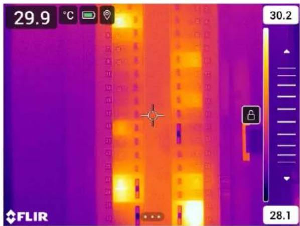
Figure 11.1 Manual adjustment mode active
11.3.3.2 Procedure
-
In live mode, push the navigation pad to display the menu system.
-
Select 3 (Temperature scale) and push the navigation pad. This displays a submenu.
- Select 📋 (Manual) and push the navigation pad.
- To simultaneously change the temperature scale minimum and maximum limits, place your finger on the screen and move it up/down.
- To change the minimum limit or the maximum limit, do the following:
- Touch the maximum or minimum temperature that you want to change.
- Place your finger on the screen and move it up/down to change the value of the highlighted temperature.
11.3.3.3 Auto-adjusting the image in manual mode
In manual image adjustment mode, you can auto-adjust the image by touching the screen. The image will be auto-adjusted based on the thermal content of the area around the touched point. The top and bottom levels in the temperature scale will be set to the maximum and minimum temperatures in that area. By using the color information only for the relevant temperatures, you will get more details in your area of interest.
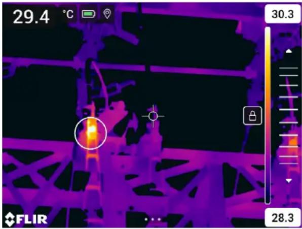
11.3.3.4 Locking the touch screen
When you have adjusted the image to levels that allow you to study your area of interest, you can lock the touch screen to prevent further unintentional adjustments.
To lock the screen, touch the icon to the left of the temperature scale.
To unlock the screen, touch the icon to the left of the temperature scale.
Note If you switch to automatic image adjustment mode, the screen automatically unlocks and your manual adjustments are lost.
11.3.4 Manual adjustment by using the navigation pad
11.3.4.1 Manual adjustment modes
There are two different settings for the manual adjustment mode (applicable for the navigation pad only):
- Level, Span: With this setting, you can manually adjust the level and span by using the navigation pad.
- Level, Max, Min: With this setting, you can manually adjust the level by using the navigation pad. You can also change the upper and lower temperatures individually.
Select the type of manual image adjustment mode under (Settings) > Device settings > User interface options > Manual adjustment mode.
11.3.5 Manual adjustment in Level, Span mode
Note This procedure assumes that you have configured the camera for manual image adjustments in Level, Span mode. Select Settings > Device settings > User interface options > Manual adjustment mode = Level, Span.
Follow this procedure:
- In live mode, push the navigation pad to display the menu system.
- Select 3 (Temperature scale) and push the navigation pad. This displays a submenu.
- Select ↗ (Manual) and push the navigation pad.
- Push the navigation pad up/down to increase/decrease the level.
- Push the navigation pad left/right to increase/decrease the span.
11.3.6 Manual adjustment in Level, Max, Min mode
Note This procedure assumes that you have configured the camera for manual image adjustments in Level, Max, Min mode. Select Settings > Device settings > User interface options > Manual adjustment mode = Level, Max, Min.
Follow this procedure:
- In live mode, push the navigation pad to display the menu system.
- Select 3 (Temperature scale) and push the navigation pad. This displays a submenu.
- Select ☑ (Manual) and push the navigation pad.
- To simultaneously change the temperature scale minimum and maximum limits, push the navigation pad up/down.
-
To change the minimum limit or the maximum limit, do the following:
-
Push the navigation pad left/right to select (highlight) the maximum or minimum temperature.
- Push the navigation pad up/down to change the value of the highlighted temperature.
11.4 Changing the camera temperature range
The camera is calibrated for different temperature ranges. Available temperature range options are dependent on the camera model.
For accurate temperature measurements, you must change the Camera temperature range setting to suit the expected temperature of the object you are inspecting.
Note For more information, see section 27 About calibration.
Follow this procedure:
- Push the navigation pad to display the menu system.
- Select ⚙️ (Settings) and push the navigation pad. This displays the Settings menu.
- Select Camera temperature range and push the navigation pad. This displays a dialog box.
- Select the appropriate temperature range and push the navigation pad.
Note You can also assign the function Switch temperature range to the programmable button. For more information, see section 7.9 Programmable button.
11.5 Changing the color palettes
You can change the color palette that the camera uses to display different temperatures. A different palette can make it easier to analyze an image.
This table explains the different types of color palettes.
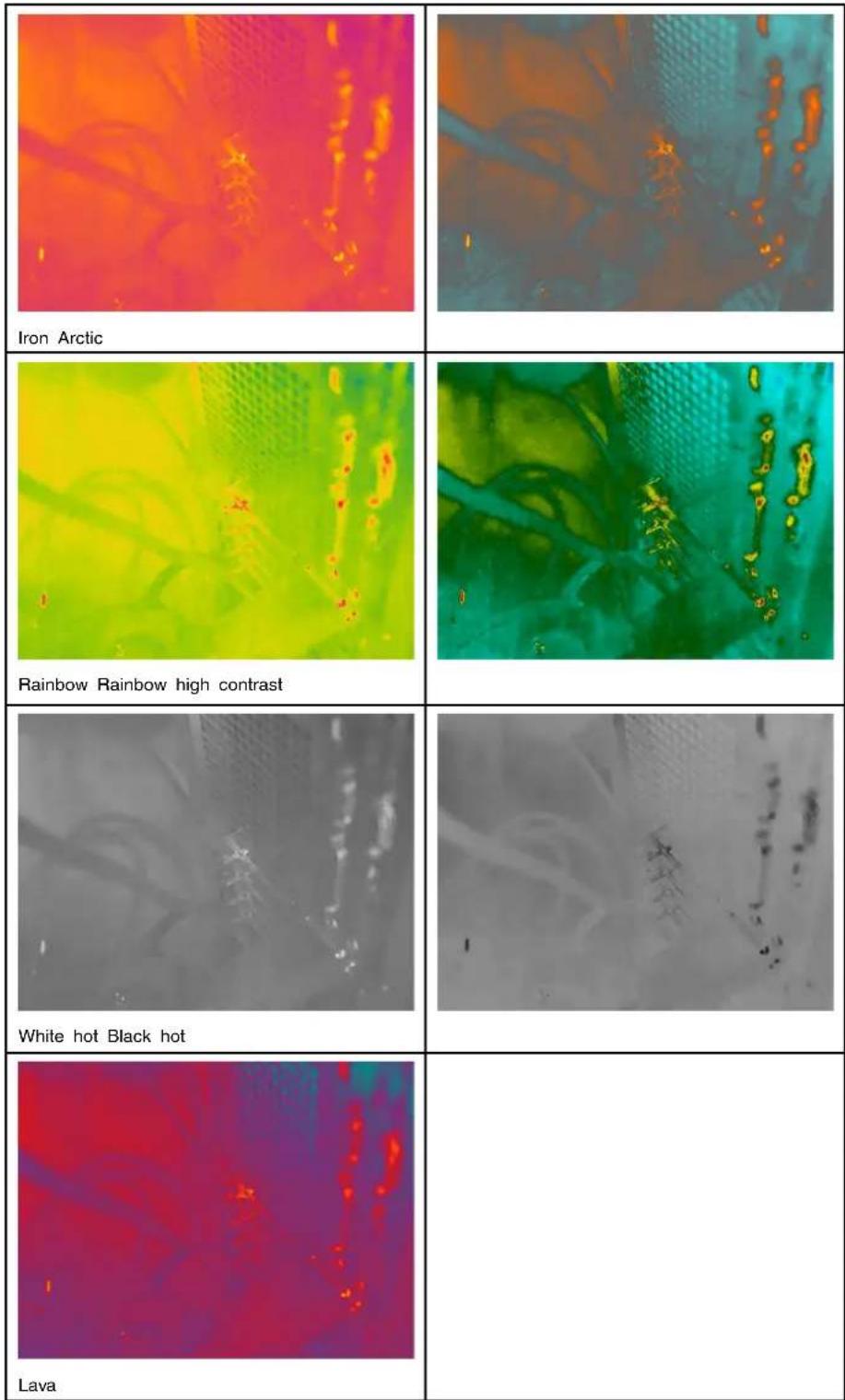
Follow this procedure:
- Push the navigation pad to display the menu system.
- Select (Color) and push the navigation pad. This displays a submenu.
-
Use the navigation pad to select a different palette.
-
Push the navigation pad to confirm and exit the menu mode.
11.6 Changing the measurement parameters
For accurate measurements, it is important to set the measurement parameters:
- Emissivity.
• Reflected temperature. - Object distance.
• Atmospheric temperature. - Relative humidity.
- External IR window compensation.
Emissivity is the most important measurement parameter to set correctly. If the Emissivity is set to a low value, the Reflected temperature also becomes important. The parameter Object distance, Atmospheric temperature, and Relative humidity are relevant for longer distances. The External IR window compensation must be activated if a protective window or external lens is used.
You can set the measurement parameters globally. You can also change the Emissivity, Reflected temperature, and Object distance parameters locally for a measurement tool.
For more information, see section 13.5 Changing the measurement parameters.
11.7 Performing a non-uniformity correction (NUC)
11.7.1 General
When the thermal camera displays Calibrating... it is performing what in thermography is called a "non-uniformity correction" (NUC). An NUC is an image correction carried out the camera software to compensate for different sensitivities of detector elements other optical and geometrical disturbances more information, see section 27 About calibration.
An NUC is performed automatically, for example at start-up, when changing a measurement range, or when the environment temperature changes.
You can also perform an NUC manually. This is useful when you have to perform a critical measurement with as little image disturbance as possible. You may, for example, want to perform a manual calibration just before you start recording a video sequence.
11.7.2 Performing an NUC manually
To perform a manual NUC, push and hold down the image archive out for more than 2 seconds.
Note You can also assign the function Calibrate to the programmable button. For more information, see section 7.9 Programmable button.
11.8 Hiding all overlay
The camera overlay consists of overlay graphics and image overlay information. The overlay graphics include items such as measurement tool symbols, result tables, and status icons. The image overlay information, which you activate on the Settings menu, provides additional information such as the date, emissivity, and atmospheric temperature. For more information, see section 6.4.5 Image overlay information.
You can choose to hide all camera overlay by pressing the programmable button.
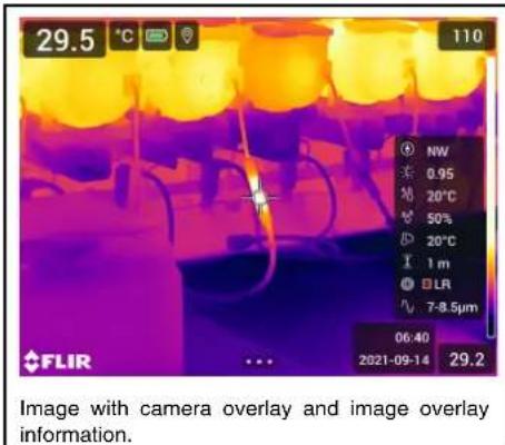

natural_image
Thermal imaging view of a hot lamp with visible flame and cooling elements (no text or symbols)Follow this procedure:
- Push and hold the programmable button. This displays the Programmable button menu.
- Push the navigation pad up/down to select the function Hide image overlay graphics
- Push the navigation pad to confirm and exit the menu mode.
12
Working with image modes
12.1 General
The camera can capture both thermal and visual images at the same time. By choosing the image mode, you select which type of image to display on the screen.
The camera supports the following image modes:
• Thermal: An infrared image is displayed.
- Thermal MSX (Multi Spectral Dynamic Imaging): The camera displays an infrared image where the edges of the objects are enhanced with visual image details.
- Picture in picture: An infrared image frame is displayed on top of the visual image.
- Digital camera: The visual image captured by the digital camera is displayed.
Note
- For the Thermal MSX, Thermal, and Picture in picture image modes, all thermal and visual information is stored when an image is saved. This means that you can edit the image later, in the image archive or in a FLIR Thermography software, and select any of the image modes.
- For the Digital camera image mode, a digital image with full resolution (5 MP) is stored when an image is saved. However, no thermal information is stored.
- You can choose to turn off the digital camera. This can, for example, be required in re-
stricted areas and in confidential (e.g., doctor/patient) situations. Select(Settings) > Save options & storage > Digital camera = Off. When the digital camera is off, only the image mode Thermal is enabled.
- The Thermal MSX, Thermal, and Picture in picture image modes only work correctly for calibrated lenses. The lens that ships with the camera is factory calibrated. To calibrate a new lens, see section 7.16 Calibrating the lens-camera combination.
12.2 Image examples
This table explains the different types of image modes.
natural_image
Thermal imaging view of a mechanical assembly with workers and equipment (no visible text or symbols)Thermal
natural_image
Thermal imaging view of an industrial vehicle interior with visible electrical connections and heat distribution (no text or symbols)Thermal MSX
natural_image
Thermal imaging view of a robotic arm with visible heat signatures and control panel (no text or symbols)Picture in picture
natural_image
Industrial machinery setup with pipes and valves in a factory setting (no visible text or symbols)Digital camera
12.3 Selecting an image mode
Follow this procedure:
- Push the navigation pad to display the menu system.
- Select (Image mode) and push the navigation pad. This displays a submenu.
- Use the navigation pad to select one of the following:
• (Thermal MSX).
- (Thermal).
• ☐ (Picture in picture).
• (Digital camera).
Note If the *.csq video format is selected (Settings > Save options & storage > Video compression) and the recording mode Video is selected (Settings > Recording mode), it will only be possible to select the image mode Thermal.
- Push the navigation pad to confirm and exit the menu mode.
- If Picture in picture mode is selected, you can at this point move and resize the infrared image frame. (For some camera models, the image frame is locked in the center and cannot be moved.) Do the following:
5.1. To activate the Picture in picture tool, touch a corner of the infrared image frame. The tool is now displayed showing five handles, one in the middle and one in every corner of the frame.
5.2. To move the frame, touch and hold the middle handle and drag the frame.
5.3. To resize the frame, touch and hold one of the corner handles and drag the corner of the frame.
Working with measurement tools
13.1 General
To measure a temperature, you can use one or more measurement tools, e.g., a spot-meter or a box.
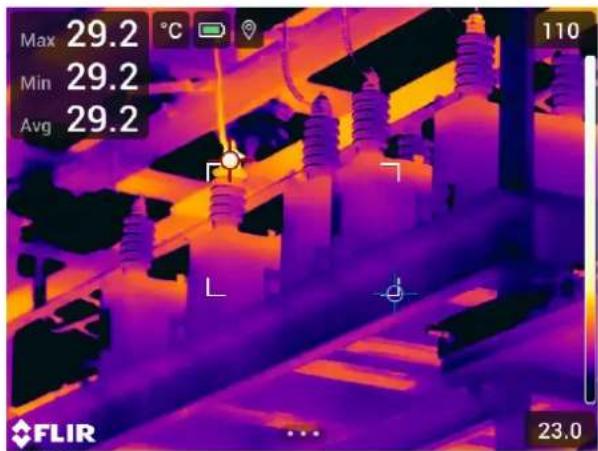
13.2 Adding/removing measurement tools
Follow this procedure:
- Push the navigation pad to display the menu system.
- Select ⚙ (Measurement) and push the navigation pad. This displays a submenu.
-
Use the navigation pad to select one of the following:
-
Select ⚙ (No measurements) to remove all tools.
- Select (Center spot) to add a center spot.
- Select (Hot spot) to add a hot spot detection within a box area.
- Select (Cold spot) to add a cold spot detection within a box area.
- Select (depending on the camera model) ^1 (User preset 1) to add user preset 1 or ✉ (3 spots) to add three spots.
-
Select (depending on the camera model) ^2 (User preset 2) to add user preset 2 or (Hot spot - Spot) to add a hot spot and a spot and display the temperature difference.
-
Push the navigation pad to confirm and exit the menu mode.
13.3 Editing user presets
Note The availability of this feature is dependent on the camera model.
A user preset is a measurement tool, or a group of measurement tools, with predefined characteristics.
Follow this procedure:
-
Push the navigation pad to display the menu system.
-
Select ⚙ (Measurement) and push the navigation pad. This displays a submenu.
- Use the navigation pad to select _1 (User preset 1) _2 (User preset 2).
- Push and hold the center of the navigation pad. This displays the Edit user preset menu.
- Select + (Add measurement) and push the navigation pad. This displays a submenu.
-
Use the navigation pad to select one of the following:
-
Select (Add spot) to add a spot.
- Select (Add box) to add a box.
- Select (Add circle) to add a circle.
-
Select (Add delta) to set up a differential calculation.
-
Push the navigation pad. This displays the measurement tool on the screen.
-
Push the navigation pad. This displays a context menu, where you can select one or more of the following actions (depending on the type of tool):
-
Remove the tool.
- Resize, move, center, and rotate the tool.
- Set alarms.
- Display maximum, minimum, average, and area values.
- Set local parameters.
- When completed, select √ (Done) and push the navigation pad.
- When all measurement tools have been added, select (Save as user preset).
- Push the navigation pad to confirm and exit the menu mode.
13.4 Moving and resizing a measurement tool
13.4.1 General
You can move and resize a measurement tool.
Note When you select another measurement tool, any changes of position and size of the current tool will be lost. If you wish to keep the position and size settings, use the us preset feature, see section 13.3 Editing user presets.
13.4.2 Moving a spot
Note You can also move the spot by touching the screen.
Follow this procedure:
- To select the spot, touch the tool on the screen. The tool is now displayed with a frame.
- Push the navigation pad—or touch and hold the tool. This displays a context menu.
- To move the spot, do the following:
3.1. Select (Move spot) and push the navigation pad.
3.2. Push the navigation pad up/down and left/right to move the spot.
-
To center the spot, select Center spot and push the navigation pad.
-
When completed, push the navigation pad and select (Done).
- Push the navigation pad to confirm and exit the menu mode.
13.4.3 Moving and resizing a box or circle tool
Note You can also move and resize the measurement tool by touching the screen.
Follow this procedure:
- To select the measurement tool, touch the tool on the screen. The tool is now displayed with one or more handles.
-
Push the navigation pad—or touch and hold the tool. This displays a context menu.
-
Select (Move/resize) and push the navigation pad. This displays a submenu.
-
Use the navigation pad to select one of the following:
-
Select ↘ (Resize) to change the size of the tool.
- Select (Move) to move the tool.
-
Select (Center box/circle) to center the tool.
-
Push the navigation pad up/down and left/right to resize or move the tool.
- When completed, push the navigation pad and select (Done).
- Push the navigation pad to confirm and exit the menu mode.
13.5 Changing the measurement parameters
13.5.1 General
For accurate measurements, it is important to set the measurement parameters.
Note During normal operation there is typically no need to change the default measurement parameters, see section 13.5.3 Recommended values.
13.5.2 Types of parameters
The camera can use these measurement parameters:
- External IR window compensation, i.e., the temperature of any protective windows, external lenses (e.g., the close-up lens), etc., that are set up between the camera and the object of interest. If no protective window, protective shield, or external lens is used, this value is irrelevant and should be left inactive.
- Object distance, i.e., the distance between the camera and the object of interest.
Note The camera can be configured to automatically measure the distance when an image is saved. With this setting, the Object distance parameter in the image data is automatically updated with the measured distance when an image is saved. (There is no effect on the Object distance setting in live mode.) For more information, see section 6.3 Laser distance meter and laser pointer.
- Atmospheric temperature, i.e., the temperature of the air between the camera and the object of interest.
- Relative humidity, i.e., the relative humidity of the air between the camera and the object of interest.
- Reflected temperature, which is used when compensating for the radiation from the surroundings reflected by the object into the camera. This property of the object is called “reflectivity.”
- Emissivity, i.e., how much radiation an object emits, compared with the radiation of a theoretical reference object at the same temperature (called a "blackbody"). The opposite of emissivity is reflectivity. The emissivity determines how much of the radiation originates from the object as opposed to being reflected by it.
Note There is an Emissivity mode setting, which you can use to enter the emissivity
by material instead of by value. Select (Settings) > Device settings > User interface options > Emissivity mode > Select from materials table.
Emissivity is the most important measurement parameter to set correctly. If the Emissivity is set to a low value, the Reflected temperature also becomes important. The parameter Object distance, Atmospheric temperature, and Relative humidity are relevant for longer distances. The External IR window compensation must be activated if a protective window or external lens is used.
13.5.3 Recommended values
If you are unsure about the values, the following are recommended:
| Object distance 1.0 m (3.3 ft.) | |
| Atmospheric temperature | 20°C (69°F) |
| Relative humidity 50% | |
| Reflected temperature 20°C (69°F) | |
| Emissivity 0.95 |
13.5.4 Procedure
You can set the measurement parameters globally. You can also change the Emissivity, Reflected temperature, and Object distance parameters locally for a measurement tool.
Local parameters are normally only effective for a fixed setup, where each measurement tool is set for a specific object of interest. For a general handheld application, the global parameters are usually sufficient.
Note Emissivity and Reflected temperature are the two most important measurement parameters to set correctly in the camera.
13.5.4.1 Setting global parameters
Follow this procedure:
- Push the navigation pad to display the menu system.
- Select (Measurement parameters) and push the navigation pad. This displays a submenu.
- Use the navigation pad to select one or more of the global measurement parameters:
• (External IR window compensation).
• (Object distance).
• (Atmospheric temperature).
• ♂ (Relative humidity).
• > (Reflected temperature).
• (Emissivity).
- Push the navigation pad to display a dialog box.
- Use the navigation pad to change the parameter.
- Push the navigation pad to confirm and exit the menu mode.
13.5.4.2 Changing local parameters
You can change the local parameters for a measurement tool.
A P next to the measurement tool on the screen indicates that local parameters have been activated for the tool.
Follow this procedure:
- To select the measurement tool, touch the tool on the screen. The tool is now displayed with one or more handles.
- Push the navigation pad—or touch and hold the tool. This displays a context menu.
- Select ☐ (Use local parameters) and push the navigation pad.
- Push the navigation pad to activate the use of local parameters. This displays a submenu.
- Use the navigation pad to select one or more of the local measurement parameters.
- Push the navigation pad to display a dialog box.
- Use the navigation pad to change the parameter.
- Push the navigation pad. This closes the dialog box.
- When completed, push the navigation pad and select (Done).
- Push the navigation pad to confirm and exit the menu mode.
Note When you select another measurement tool, the local parameters are reset. If you wish to keep the local parameter settings, use the user preset feature, see section 13.3 Editing user presets.
13.6 Displaying values in the result table
For the box and circle tools, you can set the camera to display the maximum, minimum, average, and area values in the result table.
Follow this procedure:
- To select the measurement tool, touch the tool on the screen. The tool is now displayed with one or more handles.
- Push the navigation pad—or touch and hold the tool. This displays a context menu.
- Use the navigation pad to select (Max/Min/Avg).
- Push the navigation pad. This displays a submenu.
-
Use the navigation pad to select one or more of the following:
-
Select (Max) to display the maximum value.
- Select (Min) to display the minimum value.
- Select (Avg) to display the average value.
- Select (depending on the tool) or (Area) to display the area of an object within the measurement to &l Area measurements require that the laser is enabled (Settings > Device settings > Lamp & laser > Enable lamp & laser). For more information, see section 7.6 Measuring areas.
-
Select (Max & min markers) to display the maximum and minimum markers (the hot/cold spots).
-
Push the navigation pad to toggle the function between inactive and active.
- When completed, push the navigation pad down to close the submenu.
- Select √ (Done) and push the navigation pad.
13.7 Creating and setting up a difference calculation
A difference calculation gives the difference between the values of two known measurement results.
Note
- You can set up a difference calculation when previewing an image or when editing an image in the archive.
- Depending on the camera model, you can also set up a difference calculation when defining user presets or by selecting the measurement tool Hot spot - Spot.
- This procedure assumes that you have previously laid out at least one measurement tool on the screen.
Follow this procedure:
-
To set up a difference calculation, do the following:
-
If you are defining user presets, select ^+ (Add measurement) and then select (Add delta).
-
If you are editing an image in the archive, select (Measurement) and then select (Add delta).
-
Push the navigation pad. This displays a dialog box where you can select the measurement tools that you want to use in the difference calculation. You can also select a fixed-temperature reference.
-
Push the navigation pad. The result of the difference calculation is now displayed on the screen.
13.8 Setting a measurement alarm
13.8.1 General
You can make the camera trigger an alarm when certain measurement conditions are met.
13.8.2 Types of alarm
You can choose between the following alarm types:
- Above: Triggers an alarm when the temperature is above the preset alarm temperature.
- Below: Triggers an alarm when the temperature is below the preset alarm temperature.
13.8.3 Alarm signals
When an alarm is set, the symbol is displayed in the result table.
When an alarm is triggered, the value in the result table is displayed in red (above alarm) or blue (below alarm) and the symbol (above alarm) or (below alarm) is blinking.
You can also set an audible alarm (there will be a "beep" when the alarm is triggered).
13.8.4 Procedure
There are different procedures for setting up an alarm for a spot, for a box or circle, and for a difference calculation.
13.8.4.1 Setting up an alarm for a spot
Follow this procedure:
- To select the spot, touch the tool on the screen. The tool is now displayed with a frame.
- Push the navigation pad—or touch and hold the tool. This displays a context menu.
- Select 🔊 (Set alarm on spot) and push the navigation pad. This displays a dialog box.
-
In the dialog box, you can define the settings for the alarm.
-
Alarm condition: The condition that triggers the alarm. Applicable values are Above, Below, or Off.
- Alarm limit: The temperature value that will be the critical condition when an alarm is triggered or not.
-
Alarm sound: Applicable values are Beep or No sound.
-
Push the navigation pad. This closes the dialog box.
13.8.4.2 Setting up an alarm for a box or circle
Note This procedure assumes that you have previously set the camera to display at least one value (maximum, minimum, or average) in the result table. For more information, see section 13.6 Displaying values in the result table.
Follow this procedure:
- To select the measurement tool, touch the tool on the screen. The tool is now displayed with one or more handles.
- Push the navigation pad—or touch and hold the tool. This displays a context menu.
- Select ⏻ (Set alarm) and push the navigation pad. This displays a dialog box.
-
In the dialog box, you can define the settings for the alarm.
-
Alarm condition: The condition that triggers the alarm. Applicable values are Above, Below, or Off.
- Select measurement: Applicable settings are the values you have previously defined (Max, Min, and/or Avg).
- Alarm limit: The temperature value that will be the critical condition when an alarm is triggered or not.
-
Alarm sound: Applicable values are Beep or No sound.
-
Push the navigation pad. This closes the dialog box.
13.8.4.3 Setting up an alarm for a difference calculation
Note
- You can set up an alarm for a difference calculation when defining user presets (depending on the camera model), or when editing an image in the archive.
- This procedure assumes that you have previously set up a difference calculation.
To set up an alarm for a difference calculation, do the following:
- If you are editing an image in the archive, select(Measurement).
- Select (Select) and push the navigation pad. This displays a dialog box.
- Select Delta and push the navigation pad. This displays a context menu.
-
Select 🔊 (Set alarm on delta) and push the navigation pad. This displays a dialog box.
-
In the dialog box, you can define the settings for the alarm.
-
Alarm condition: The condition that triggers the alarm. Applicable values are Above, Below, or Off.
- Alarm limit: The temperature value that will be the critical condition when an alarm is triggered or not.
-
Alarm sound: Applicable values are Beep or No sound.
-
Push the navigation pad. This closes the dialog box.
Working with color alarms and isotherms
14.1 Color alarms
By using color alarms (isotherms), anomalies can easily be discovered in an infrared image. The isotherm command applies a contrasting color to all pixels with a temperature above, below, or between the set temperature levels. The camera also features isotherm types that are specific to the building trade: condensation and insulation alarms.
You can make the camera trigger the following types of color alarms:
- Above alarm: This will apply a contrasting color to all pixels with a temperature above the specified temperature level.
- Below alarm: This will apply a contrasting color to all pixels with a temperature below the specified temperature level.
- Interval alarm: This will apply a contrasting color to all pixels with a temperature between two specified temperature levels.
- Condensation alarm: Triggers when the camera detects a surface where the relative humidity exceeds a preset value.
- Insulation alarm: Triggers when there is an insulation deficiency in a wall.
This table explains the different color alarms (isotherms).
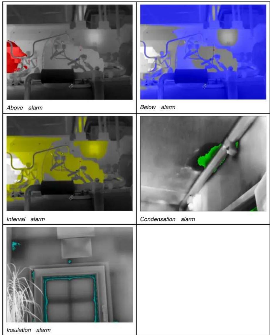
14.1.1 Setting up above, below, and interval alarms
- Push the navigation pad to display the menu system.
- Select (Color) and push the navigation pad. This displays a submenu.
- Use the navigation pad to select one of the following:
• (Above alarm).
• (Below alarm).
• (Interval alarm).
- Push the navigation pad. This displays a dialog box where you can define the settings for the alarm.
For the Above alarm and Below alarm, the following parameters can be set:
- Temperature limit.
- Palette.
For the Interval alarm, the following parameters can be set:
- Low temperature.
• High temperature. -
Palette.
-
Push the navigation pad. This closes the dialog box.
14.1.2 Building isotherms
Note The Condensation and Insulation alarms are not supported by all camera models.
14.1.2.1 About the Condensation alarm
To detect areas with potential moisture problems, you can use the Condensation alarm. You can set the relative humidity above which the isotherm will colorize the image.
14.1.2.2 About the Insulation alarm
The Insulation alarm can detect areas where there may be an insulation deficiency in the building. It will trigger when the insulation level (which is called the thermal index in the camera) falls below a preset value of the energy leakage through a wall.
Different building codes recommend different values for the insulation level, but typical values are 60–80% for new buildings. Refer to your national building code for recommendations.
14.1.2.3 Setting up condensation and insulation alarms
- Push the navigation pad to display the menu system.
- Select (Color) and push the navigation pad. This displays a submenu.
- Use the navigation pad to select one of the following:
• (Condensation alarm).
• (Insulation alarm).
- Push the navigation pad. This displays a dialog box where you can define the settings for the alarm.
For the Condensation alarm, the following parameters can be set:
- Atmospheric temperature: The current atmospheric temperature.
- Relative humidity: The current relative humidity.
- Relative humidity limit: The relative humidity level at which you want the alarm to be triggered. A relative humidity of 100% means that water vapor condenses from the air as liquid water (= dewpoint). A relative humidity of about 70% or above can cause mold.
For the Insulation alarm, the following parameters can be set:
- Indoor temperature: The current indoor temperature.
- Outdoor temperature: The current outdoor temperature.
-
Thermal index: The insulation level (an integer between 0 and 100).
-
Push the navigation pad. This closes the dialog box.
15.1 General
You can save additional information with an infrared image by using annotations. Annotations make reporting and post-processing more efficient by providing essential information about the image, e.g., conditions and information about where an image is taken.
Annotations are added to the image file and can be viewed and edited in the camera or in a FLIR Thermography software.
- You can set the camera to display annotation tools when an image is saved. Select
(Settings) > Save options & storage > Add annotation after saving.
- You can also add annotations to a saved image in the image archive.
Note This section describes the procedures for adding annotations to a saved image in the image archive. Adding annotations when saving an image works in a similar way.
15.2 Adding a note
You can add a text note to the image file. Using this feature, you can annotate images by entering free-form text.
Follow this procedure:
- Open the image in the image archive.
- Push the navigation pad to display the top toolbar.
- On the top toolbar, select the icon and push the navigation pad.
- On the right toolbar, select the icon and push the navigation pad.
- A soft keyboard is displayed, where you can enter text by touching the screen.
- When completed, touch Done on the soft keyboard.
15.3 Adding a text comment table
You can save a table with textual information to the image file. This feature is a very efficient way of recording information when you are inspecting a large number of similar objects. The idea behind using a table with textual information is to avoid filling out forms or inspection protocols manually.
The camera ships with an example text comment table template. You can also create your own templates. For more information, see section 15.3.1 Creating a text comment table template.
Follow this procedure:
- Open the image in the image archive.
- Push the navigation pad to display the top toolbar.
- On the top toolbar, select the* icon and push the navigation pad.
- On the right toolbar, select the icon and push the navigation pad. This displays a table.
- (Optional step.) On the top toolbar, do one of the following:
- To clear the content of the current table, select the icon and push the navigation pad.
- To select another table template, select the icon and push the navigation pad.
-
For each row in the table, do the following:
-
Push the navigation pad. This displays the predefined values.
- Push the navigation pad up/down to select a predefined value. Push the navigation pad to confirm.
- Instead of selecting a predefined value, you can select the keyboard icon and enter other text by touching the screen.
Note Text entered by the keyboard will be saved to the text comment table template. Next time you add a text comment table annotation, the entered text will be displayed as a predefined value.
- When completed, select Save & Exit at the bottom of the table. Push the navigation pad to confirm.
15.3.1 Creating a text comment table template
You can create a text comment file manually. You can also create a text comment file using a FLIR Thermography software.
15.3.1.1 Manually creating a table template
A text comment file (*.tcf) is an annotation format that is proprietary to FLIR Systems. It defines a table structure that can be used to add text table annotations to FLIR images. You can create text comment files (*.tcf files) and use these files as table templates in the camera.
The camera ships with an example text comment table file: example_text_comment.tcf. The file is stored on the memory card in the subfolder \TextTableTemplates. You can make a copy of the example file and modify it using a text editor such as Microsoft Notepad.
When creating or modifying a text comment file, keep the following rules in mind:
- Lines starting with “#” are regarded as comments and will be ignored.
- Lines that start with "<" and end with "> " are labels and will appear on the left-hand side of the table.
- Non-empty lines under a label line are regarded as values and will be displayed as options to the label above.
- When you save the file, select UTF-8 encoding. With UTF-8 encoding, the file will support all languages currently supported by the camera.
-
The template will be updated by the camera if you add or remove values in the text table annotations dialog in the camera. This enables you to modify its content while you are working with the camera.
-
The camera will find all text table template files if:
-
They are placed on the memory card in the subfolder \TextTableTemplates.
- They have an ASCII filename and the file extension .tcf. (ASCII characters include a-z, A-Z, 0-9, and basic punctuation, and spaces can be used. The file can contain non-ASCII text, but the filename must be ASCII.)
15.3.1.1.1 Example mark-up structure
The file format for the text comment table template is *.tcf. This code sample is an example mark-up structure of such a file, and shows how the mark-up appears in a text editor such as Notepad.
<Site>
Company A
Company B
<Location>
Substation A
<Object>
Engine
Vent
Vault
Door
<ObjectID>
A1a1
A1b2
A1c3
<Deviation>
Overload
Moisture
Draft
<Remedy>
Replace
Fix
No action
<Severity>
Critical
Non-critical
<Severity>
15.4 Adding a voice annotation
A voice annotation is an audio recording that is saved to the infrared image file. The recording can be played back in the camera, and in image analysis and reporting software from FLIR Systems.
The voice annotation is recorded using the built-in microphone. You can also use a Bluetooth-enabled headset. For information on how to pair a headset with the camera, see section 21 Pairing Bluetooth devices.
Follow this procedure:
- Open the image in the image archive.
- Push the navigation pad to display the top toolbar.
- On the top toolbar, select the icon and push the navigation pad.
- On the right toolbar, select the icon and push the navigation pad.
- A context menu is displayed.
- To start a recording, select (Record) and push the navigation pad.
- To stop the recording, select □ (Stop) and push the navigation pad.
- To listen to the recording, select (Play) and push the navigation pad.
- To delete the recording, select (Delete) and push the navigation pad.
- When completed, select Down (Done) and push the navigation pad.
15.5 Adding a sketch
You can add a freehand drawing to an infrared image.
Follow this procedure:
- Open the image in the image archive.
- Push the navigation pad to display the top toolbar.
- On the top toolbar, select the icon and push the navigation pad.
- On the right toolbar, select the icon and push the navigation pad.
-
You are now in sketch mode. Draw the sketch by touching the screen.
-
(Optional step.) Push the navigation pad. This displays a context menu. Do one or more of the following:
-
To change the color of the sketch tools, select (Draw) and push the navigation pad. Select the color and push the navigation pad.
- To erase, select (Eraser) and push the navigation pad. Erase parts of the sketch by touching the screen.
- To add an arrow, circle, or cross, select (Stamp sketch) and push the navigation pad. Select the type of stamp and push the navigation pad. The stamp is displayed in the center of the screen. You can move the stamp by using the navigation pad or by touching the screen. When completed, push the navigation pad.
- To clear, select (Clear all) and push the navigation pad.
- When the sketch is completed, select (Save) and push the navigation pad.
Programming the camera (time-lapse)
Note The availability of this feature is dependent on the camera model.
You can program the camera to save images periodically (time-lapse).
Follow this procedure:
- Push the navigation pad to display the menu system.
- Select ⚙️ (Settings) and push the navigation pad. This displays the Settings menu.
- Use the navigation pad to select Recording mode > Time-lapse.
-
Push the navigation pad. This displays a dialog box where you can set the save conditions:
-
Save interval: Use the navigation pad to set the time interval between each saved image.
- Total number of images: Periodic saving will stop when the set number of images have been saved.
Note If you select “∞,” the camera will keep on saving images until the memory card is full or until you manually stop the time-lapse.
-
Push the navigation pad. This closes the dialog box.
-
Push the back button repeatedly to exit the Settings menu.
- The time interval is displayed at the top of the screen.
- To start the time-lapse (periodic saving), pull and release the trigger.
- To manually stop the time-lapse, pull and release the trigger.
- When the time-lapse is completed, an information screen is displayed. Push any button or touch the screen to return to the live image.
Recording video clips
17.1 General
You can record and save video clips to the memory card.
Note The camera can be configured to save video in *.mpg or *.csq format. Select (Settings) > Save options & storage > Video compression.
- Mpeg (*.mpg): Mpeg recordings cannot be edited after the file has been saved.
- Radiometric storage (*csq)A *.csq file supports full radiometry but is only supported by FLIR Systems software. The file does not include any visual image information. With this setting, only Thermal image mode is supported when recording video. If any other image mode is active when Video recording mode is selected, the camera will auto-switch to Thermal image mode.
17.2 Recording a video clip
- Push the navigation pad to display the menu system.
- Select ⚙️ (Settings) and push the navigation pad. This displays the Settings menu.
- Use the navigation pad to select Recording mode > Video.
- Push the back button ↩ to exit the Settings menu.
- To start a recording, pull and release the trigger. A counter at the top of the screen displays the duration of the recording.
- To stop a recording, pull and release the trigger. The recording is automatically saved to the image archive.
17.3 Playing a saved video clip
- Push the image archive button ▶ This displays the Gallery with one or more folders.
- Select a folder and push the navigation pad.
- Select the video clip you want to play and push the navigation pad.
- Push the navigation pad to display the top toolbar.
- On the top toolbar, select the icon and push the navigation pad.
- To play or pause the video clip, push the navigation pad.
Inspection Route
18.1 General
FLIR Inspection Route is a solution that streamlines thermal inspections and simplifies data collection and reporting. The solution includes FLIR software and camera support for preparation, inspection, and post-processing.
With the Inspection Route function, the camera guides the operator along a predefined route of inspection points, where images and data are collected in a structured manner. FLIR Inspection Route speeds up post-processing and reporting by ensuring that nothing is missed and that all inspection results are organized right from the start.
The inspection work flow is defined by an inspection route file, with a high degree of flexibility. It is possible to configure an automated work flow, where the camera automatically sets the status and steps to the next inspection point when an image is saved. The operator can also manually select the status, add comments, and add more images.
The inspection route work flow typically involves the following steps:
- Prepare the inspection route file, using one of the following methods:
• The FLIR Thermal Studio application.
- Your own solution. The FLIR Thermal SDK can be used to build your own export/import software or to interface your existing asset management system.
- Create a file in the camera.
- Manually edit a file.
- Add the inspection route file to the camera memory card.
- Perform the inspection using the camera.
- Move the results from the camera using the USB cable or the memory card, or upload the results to FLIR Ignite.
- Import the results into FLIR Thermal Studio or your own image management and reporting system.
- Create an inspection route report.
18.1.1 FLIR Inspection Route Solution user manual
The FLIR Inspection Route Solution user manual describes how to configure an inspection route file, perform an inspection, transfer the inspection results, and create an inspection report using a camera with FLIR Inspection Route enabled, the FLIR Thermal Studio application, and the FLIR Ignite cloud service.
To access the FLIR Inspection Route Solution user manual, go to http://support.flir.com/resources/route.
18.2 User interface
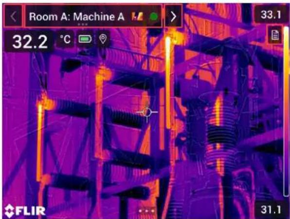
The Inspection Route overlay consists of the following parts:
- Back arrow
Tap to go to the previous inspection point.
- Current point indicator
- Displays the name of the current inspection point.
- Displays an image icon if there is an image saved for the inspection point.
- Displays the status of the inspection point.
- Next arrow
Tap to go to the next inspection point.
- Document icon
This icon is displayed if there is a description and/or comment available for the inspection point. A description comes from the inspection route file and can, for example, include instructions or reminders for the inspection point. Comments are text notes added during the inspection. Tap the icon to display the description and/or comment.
18.2.1 Drop-down menu
To display the drop-down menu, tap the current point indicator.
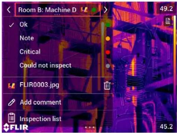
In the drop-down menu it is possible to:
- Set the status of the current inspection point.
• View the filenames of images and videos saved for this inspection point. - Add comments for the current inspection point.
- Open the inspection list, see section 18.2.2 Inspection list.
18.2.2 Inspection list
The inspection list gives an overview of the routes and their progress. It also allows editing of the inspection route.
The contents of the inspection list are defined by the inspection route file. The route structure and names come from the file.
To open the inspection list, tap the current point indicator and then tap Inspection list.
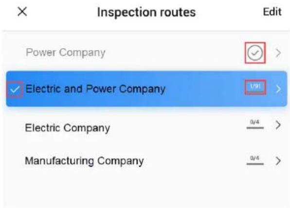
Figure 18.1
Figure 18.1 shows an example of the inspection list:
- The first inspection route is completed and locked, which is indicated by the check mark to the right.
- The second inspection route has started. It includes a total of 91 inspection points, and one of them has been inspected. The second inspection route includes the current inspection point in live view, which is indicated by the check mark to the left.
To display the next level in the inspection route structure, tap an item in the list.
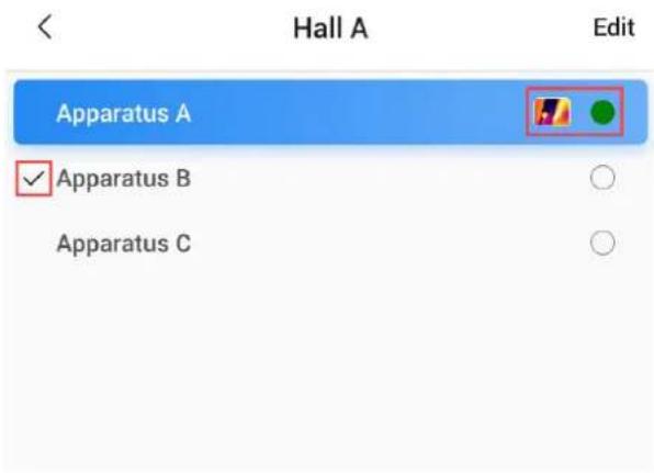
Figure 18.2
Figure 18.2 shows an example of a level with inspection points:
- The first inspection point has one or more images and the status is set to "green."
- The second inspection point is the current inspection point in live view, which is indicated by the check mark to the left.
18.3 Performing an inspection
18.3.1 Preparation
Note This procedure assumes that an inspection route file has been created. For more information, see section 18.5 Creating an inspection route.
- Add the inspection route file to the root folder on the memory card.
- Insert the memory card into the camera.
-
Start the camera.
-
Activate the Inspection Route function by selecting (Settings) > Save options & storage > Inspection route, and then toggle the Inspection route switch.
-
The camera is now ready.
18.3.2 Capturing inspection data
Once the camera is prepared, the inspection can start.
Note You can turn off the camera in the middle of an inspection. The camera will always save all data. When the camera is turned on again, it will display the first uncompleted inspection point.
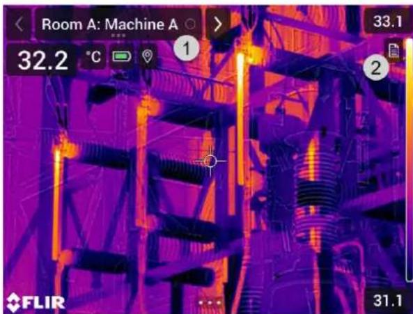
-
The current point indicator displays which inspection point to inspect.
-
To view a description of the inspection point, e.g., instructions or reminders, tap the document icon.
Note The document icon is only displayed if there is a description and/or comment available for the inspection point.
- When you are at the inspection point, take an image. The camera automatically saves the image and sets the default status.
Note The default status is defined by the inspection route file. It is possible to change the default status in the camera, see section 18.4 Configuration.
-
To edit the inspection point data, tap the current point indicator. This displays a dropdown menu where you can do the following:
-
Set the status of the inspection point, see section 18.3.3.1 Setting the status.
- Delete the image, see section 18.3.3.2 Deleting an image.
- Add a comment, see section 18.3.3.3 Adding a comment.
Note Make sure the current point indicator displays the inspection point you want to edit. If not, use the back or next arrow.
- Tap the next arrow to continue to the next inspection point.
Note The camera can be configured to automatically continue to the next inspection point after saving an image, see section 18.4 Configuration.
-
When you have completed the last inspection point in the route, a dialog box is displayed.
-
To lock the inspection, select Lock.
-
If you want to make any additional changes to the inspection, select Cancel. You make the changes from the inspection list, see section 18.3.7 Inspection list.
-
Continue the inspection until you have completed all inspection points in all routes. You can at any point open the inspection list to see an overview of the routes and their progress, see section 18.3.7 Inspection list.
-
When you have completed the inspection, transfer the inspection results to a computer for post-processing. For more information, see section 18.3.9 Transferring inspection results.
18.3.3 Editing inspection point data
You can edit the data for the inspection point displayed by the current point indicator.
To go to another inspection point, use the back or next arrow or select the inspection point from the inspection list, see section 18.3.7 Inspection list.
18.3.3.1 Setting the status
- Tap the current point indicator. This displays a drop-down menu.
- Tap the status you want to set. The set status is indicated by a check mark in the menu and by a color in the current point indicator.
Note
- The available statuses are defined by the inspection route file.
- Depending on the inspection route configuration, it may be necessary to take an image before a status can be set.
18.3.3.2 Deleting an image
- Tap the current point indicator. This displays a drop-down menu.
- Tap ☐ to delete the image. This displays a dialog box.
- To delete the image, tap Delete.
18.3.3.3 Adding a comment
- Tap the current point indicator. This displays a drop-down menu.
- Tap Add comment. This displays a soft keyboard.
- Enter text by touching the screen.
- When completed, tap Done.
- The comment is displayed in the drop-down menu. You can also see the comment by tapping the document icon.
18.3.4 Saving an image
When you take an image, the camera automatically saves it to the memory card. The image is stored in a folder with the name of the current inspection route.
You can take and save multiple images of the inspection point.
Note For every new image, make sure that the current point indicator displays the inspection point you want to add the image to. If not, use the back or next arrow or select the inspection point from the inspection list, see section 18.3.7 Inspection list.
18.3.5 Recording a video clip
You can record and save video clips of the inspection point. For more information, see section 17 Recording video clips.
Note Make sure that the current point indicator displays the inspection point you want to add the video to. If not, use the back or next arrow or select the inspection point from the inspection list, see section 18.3.7 Inspection list.
18.3.6 Viewing and editing inspection images
You can view and edit the inspection images in the image archive.
Note It is not possible to edit the inspection point data in the image archive. To edit the inspection point data, see section 18.3.3 Editing inspection point data.
18.3.7 Inspection list
In the inspection list, you can see the progress of the inspection routes and review the inspection point results.
To see the progress and review the results, do the following:
- Tap the current point indicator. This displays a drop-down menu.
- Tap Inspection list. This displays a list with all inspection routes and their progress.
- Tap an item in the list to display the next level in the inspection route structure.
- When you reach a level with inspection points, you can see their status and if they have any images associated.
- To make changes to an inspection point, tap the inspection point in the list. This takes you to the live view for that inspection point.
Note You can only make changes to inspection points in unlocked inspection routes.
18.3.8 Adding an inspection point
If the need for another inspection point arises during the inspection, you can add the inspection point directly in the camera. The new inspection point will be added to the inspection route file and the inspection data you capture for the new inspection point will be saved together with the results from the other inspection points in the route.
To add an inspection point, do the following:
- Tap the current point indicator. This displays a drop-down menu.
- Tap Inspection list. This displays a list with all inspection routes.
- In the list, tap the inspection route where you want to add the inspection point. This displays the next level in the route structure.
-
Continue to tap an item in the list until you reach the level where you want to add the inspection point.
-
Tap Edit to enter edit mode.
-
Tap the + icon on an item. The new inspection point will be added below this item.
-
Enter the name of the new inspection point.
-
Select to add the new item as an inspection point.
-
Tap Done to exit edit mode.
18.3.9 Transferring inspection results
The inspection results are stored on the memory card:
- The inspection route file (.xml) in the root folder includes the data (status, comments, and image file path) for all inspection points.
- The DCIM folder includes folders with the images for each route.
You can upload the inspection results to your FLIR Ignite account or transfer the result files manually using the USB cable or the memory card. You can also open the results from the memory card and save them to a computer using FLIR Thermal Studio.
When you have transferred and safely stored the inspection results, you may want to remove the inspection route file and images from the camera.
18.3.9.1 Upload results to FLIR Ignite
- Make sure the camera is connected to the internet.
- Make sure the camera is paired with your FLIR Ignite account.
- Select ⚙️ (Settings) > Save options & storage > Inspection route > Upload inspection route.
- The camera now creates a compressed file (.route), which includes the inspection route file (.xml) and the image folders. The camera then uploads the compressed file (.route) to your FLIR Ignite account.
18.3.9.2 Move results manually
If you transfer the inspection results manually to a computer, you must move both the inspection route file (.xml) and the images in their route folders. It is important to maintain the DCIM folder structure.
- Connect the camera to the computer with a USB cable or insert the memory card into the computer.
- On the computer, create a folder for the inspection results. In that folder, create a subfolder named DCIM.
- From the root of the memory card, transfer the inspection route file (.xml) to the inspection results folder on the computer.
- From the DCIM folder on the memory card, transfer the image folders to the DCIM subfolder on the computer.
18.3.9.3 Remove results from camera
When you have transferred and safely stored the inspection results, you may want to remove or replace the inspection route file on the memory card. If this is not done, the camera will continue from the first uncompleted inspection point in the previous inspection when you start an inspection.
If you choose to keep, remove, or replace the current inspection route file depends on your inspection work flow and how your inspection route is designed. Some examples:
- You have uploaded some results, but not yet completed the entire inspection. You keep the current inspection route file (.xml) and continue with your inspection.
- You have an inspection route file with inspections for each day of the week and you have just transferred the results from the Monday inspection. You keep the current inspection route file (.xml) to be ready for the Tuesday inspection.
- Next time you use the camera, you will do a new inspection. You remove the current inspection route file (.xml) and add a new inspection route file (.xml) file without any data to the root folder on the memory card.
Note Do not add multiple inspection route files (.xml) in the root folder on the memory card.
You may also want to remove the inspection image folders and/or the inspection images from the DCIM folder on the memory card. The camera will create new image folders when a new inspection starts.
18.4 Configuration
The behavior of the camera during the inspection route is controlled via settings in the inspection route file. It is possible to override these settings in the camera.
The camera behavior settings can be configured via the Settings menu. Select Settings) > Save options & storage > Inspection route > Configure.
Configure menu:
- Follow Inspection route: Select the check box to use the configuration from the inspection route file. Deselect the check box to make it possible to override the settings in the inspection route file.
- Auto next: This setting defines if the camera after saving an image automatically will set the default status and step to the next inspection point. If most inspection points will have the default status, you will save inspection time by selecting the check box. If you often want to set the status or add comments to the inspection points, it may be more convenient to deselect the check box.
- Default status: This submenu is used to select the status to be set when an image is saved. The options in the submenu come from the inspection route file.
- Require image: This setting defines if the operator must save an image before it is possible to set the status of an inspection point.
- Delete empty inspection points: This setting defines if all empty inspection points (no image and no status) will be removed from the inspection route file when the operator locks an inspection.
18.5 Creating an inspection route
The inspection route is defined by an XML file. The inspection route XML file specifies the route structure, consisting of multiple levels of nodes (sites/assets) and inspection points.
The inspection route file also defines the available statuses and the configuration of the camera behavior.
The inspection route file can be created using one of the following methods:
• The FLIR Thermal Studio application.
- Your own solution. The FLIR Thermal SDK can be used to build your own export/import software or to interface your existing asset management system.
- Create a file in the camera.
- Manually edit an XML file.
18.5.1 Creating an inspection route in the camera
- Make sure that there is no inspection route XML file on the memory card.
- Select ⚙️ (Settings) > Save options & storage > Inspection route > Getting started > Create an empty Inspection route. This places a basic XML file on the memory card.
- In live mode, tap the current point indicator. This displays a drop-down menu.
- Tap Inspection list. This displays a list with a node placeholder.
- Tap Edit to enter edit mode.
-
In edit mode, use the following buttons to build the inspection route:
-
Tap + to add a new item below the selected one. You can select the name of the new item and select if the new item is a node or an inspection point.
- Tap 📄 to delete the selected item and all of its dependents.
-
Tap to add comments to the node. These comments will apply to all of its dependents.
-
Tap Done to exit edit mode.
- To make changes to the camera behavior configuration, see section 18.4 Configuration.
- When the inspection route is completed, make sure to copy the XML file on the memory card to a computer for future use. When you start an inspection in the camera, the inspection data will be written to the XML file on the memory card.
18.5.2 Manually editing an XML file
An example or empty XML file can be created on the memory card in the camera. This file can be used as a basis when manually editing an XML file.
- Make sure that there is no inspection route XML file on the memory card.
-
Select ⚙️ (Settings) > Save options & storage > Inspection route > Getting started.
-
Select one of the following:
-
Create an example Inspection route: This creates an example XML file with a multi-level structure on the memory card.
-
Create an empty Inspection route: This creates a basic XML file on the memory card.
-
Transfer the example XML file to a computer for editing.
The screening alarm can be used to detect temperature anomalies in a series of inspected objects in a similar/fixed setup.
19.1 General
The basics of the screening alarm is to first build up a base of reference temperature samples. When an object is screened, the camera compares the measured temperature with the average of the reference samples. If the camera detects a temperature that is above a specified threshold, an alarm will trigger.
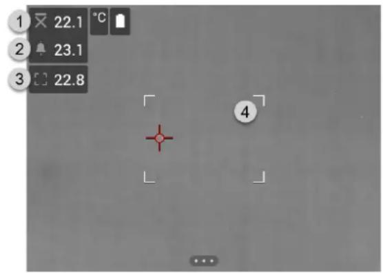
- Sampled average temperature.
- Alarm limit.
- Measured temperature.
- Measurement box.
The camera detects and measures the temperature of the hottest spot within the measurement box.
An alarm will trigger when the measured temperature is higher than the alarm limit. The camera will also apply a red color to all parts of the image with a temperature above the alarm limit.
The alarm limit is the sum of a sampled average temperature and a specified allowed deviation.
19.2 Work flow
The screening work flow involves the following steps:
- Activate and configure the screening alarm.
- Record reference samples.
- Perform the screening.
- Record new samples to keep the sampled average up to date.
19.2.1 Activate and configure the screening alarm
- Activate the screening alarm by selecting ⚙️ (Settings) > Recording mode > Screening.
- In the Screening dialog box, you can define the settings for the alarm:
- Allowed deviation: The allowed deviation from the sampled average.
- Alarm sound: Beep or no sound when the alarm triggers.
19.2.2 Record reference samples
Before the screening can start, you must record reference samples. These are used to calculate the reference temperature average.
You record the reference samples by screening 10 inspection objects. Make sure these objects have a normal temperature.
- Aim the camera toward an inspection object with a normal temperature. The object should be within the frame of the measurement box.
-
Adjust the camera focus.
Note It is important to adjust the focus correctly. Incorrect focus adjustment affects the temperature measurement. -
To record a sample, push the programmable button.
Note Push the programmable button shortly. If you push and hold the button, the sampled average will be reset.
- Repeat the steps above until 10 samples have been recorded.
19.2.3 Perform the screening
- Aim the camera toward an inspection object. The object should be within the frame of the measurement box.
- Adjust the camera focus.
Note It is important to adjust the focus correctly. Incorrect focus adjustment affects the temperature measurement.
-
The camera measures and evaluates the temperature. If the temperature is higher than the alarm limit, an alarm will trigger. The camera will apply a red color to all parts of the image with a temperature above the alarm limit.
-
Optionally: Record a new sample.
Push the programmable button.
Note Push the programmable button shortly. If you push and hold the button, the sampled average will be reset.
Note Every time you push the programmable button, a sample is recorded. If you happen to record a sample when the camera is not aiming at an inspection object, you must reset the sampled average and record 10 new samples. To reset the sampled average, push and hold the programmable button.
Depending on your camera configuration, you can connect the camera to a wireless local area network (WLAN) using Wi-Fi, or let the camera provide Wi-Fi access to other devices.
You can connect the camera in two different ways:
- Setting up the camera as a wireless access point. This method is primarily used with other devices, e.g., an iPhone or iPad.
- Connecting the camera to a Wi-Fi network.
The Wi-Fi functionality is managed from the Settings menu. You can also enable/disable Wi-Fi on the swipe-down menu. For more information, see section 6.4.4 Swipe-down menu.
20.1 Setting up a wireless access point
- Push the navigation pad to display the menu system.
- Select ⚙️ (Settings) and push the navigation pad. This displays the Settings menu.
- Use the navigation pad to select Connections > Wi-Fi.
- Select Share and push the navigation pad.
-
(Optional step.) To display and change the parameters, select Share settings and push the navigation pad.
-
To change the SSID, select Network name (SSID) and push the navigation pad.
- To change the WPA2 password, select Password and push the navigation pad.
Note These parameters are set for your camera's network. They will be used by the external device to connect that device to the network.
- Toggle the switch to enable/disable the firewall for the network shared by the camera.
Note To enable/disable the camera firewall, select Connections > Advanced > Global firewall.
20.2 Connecting the camera to Wi-Fi
- Push the navigation pad to display the menu system.
- Select ⚙️ (Settings) and push the navigation pad. This displays the Settings menu.
- Use the navigation pad to select Connections > Wi-Fi.
- Select Connect to network and push the navigation pad.
- To display a list of the available networks, select Available networks and push the navigation pad.
- Select one of the available networks and push the navigation pad.
Note Password-protected networks are indicated with a padlock icon, and for these you will need to enter a password the first time you connect to the network. After that the camera will connect automatically to the network. To disable the automatic connection, select Forget network.
Note Some networks do not broadcast their existence. They appear in the list as Untitled. To connect to such a network, you will be prompted to enter additional parameters.
Note To enable/disable the camera firewall, select Connections > Advanced > Global firewall.
Pairing Bluetooth devices
You can use the camera with the following Bluetooth devices:
• METERLINK devices (FLIR meters).
- Bluetooth-enabled headsets.
If supported by your mobile phone, you can also share the phone's internet connection with the camera via Bluetooth.
Note The Bluetooth protocol is limited in terms of data transfer and best suited for upload of single images. For upload of videos and folders with several images, it is recommended to use Wi-Fi.
Before you can use a Bluetooth device with the camera, you need to pair the devices. The Bluetooth functionality is managed from the Settings menu. You can also enable/disable Bluetooth on the swipe-down menu. For more information, see section 6.4.4 Swipe-down menu.
Follow this procedure:
- Push the navigation pad to display the menu system.
- Select ⚙️ (Settings) and push the navigation pad. This displays the Settings menu.
- Use the navigation pad to select Connections > Bluetooth.
- Make sure Bluetooth is enabled by toggling the Bluetooth switch.
Note You also need to ensure that the external Bluetooth device is in visible mode. On the mobile phone, you must make sure that Bluetooth is enabled, that the phone is in discovery mode, and that Bluetooth tethering is enabled.
- Select Available devices and push the navigation pad.
- Wait until a list of available Bluetooth devices is displayed.
- When a Bluetooth device is found, select the device to add it, and begin the pairing procedure. The device is then ready to be used.
Note
- You can add several devices.
- You can remove a device by selecting the device and then selecting Unpair device.
- After adding a METERLINK device, such as the FLIR MR77 or FLIR DM93, the result from the meter will be visible in the result table and stored with the images. For more information, see section 22 Fetching data from external FLIR meters.
- After adding a Bluetooth-enabled headset, it is ready to be used for adding voice annotations.
Fetching data from external FLIR meters
22.1 General
You can fetch data from some external FLIR meters that support Bluetooth and merge this data into the infrared image. When the camera is connected to a FLIR meter via Bluetooth, the measurement value from the meter is displayed in the result table of the camera. The FLIR meter value is also added to the information saved in the image file.
In preview mode and when editing an image in the archive, you can add more than one value from the same FLIR meter. The last added value is displayed below the previous values. The live value is displayed with a dotted outline.
If the screen display for values is full, it is still possible to add more values from the FLIF meter. Added values are then indicated by a box with a number that counts up each time a new value is added.
To find out whether a FLIR meter is supported by the camera, consult the meter documentation.
22.2 Technical support for external meters
| Technical support | |
| Website http://support.flir.com | |
22.3 Procedure
Note
- Before you can use a FLIR meter with the camera, you need to pair the devices. For more information, see section 21 Pairing Bluetooth devices.
- To add more than one FLIR meter value when saving an image, preview mode must be enabled. Select (Settings) > Save options and storage > Preview image before saving = On.
Follow this procedure:
- Turn on the camera.
- Turn on the FLIR meter.
- On the FLIR meter, enable Bluetooth mode. Refer to the user documentation for the meter for information on how to do this.
- On the FLIR meter, choose the quantity that you want to use (voltage, current, resistance, etc.). Refer to the user documentation for the meter for information on how to do this.
Results from the meter will now automatically be displayed in the result table in the top left corner of the infrared camera screen.
-
On the camera, in preview mode and when editing an image in the archive, you can do the following:
-
Push the programmable button to add the value currently displayed by the FLIR meter.
- Push and hold the programmable button to remove all FLIR meter values from the image.
Note Any function assigned to the programmable button is temporarily disabled when in preview mode or when editing an image in the archive.
22.4 Typical moisture measurement and documentation procedure
The following procedure can form the basis for other procedures using FLIR meters and infrared cameras.
- Use the infrared camera to identify any potential damp areas behind walls and ceilings.
- Use the moisture meter to measure the moisture levels at various suspect locations that may have been found.
- When an area of particular interest is located, store the moisture reading in the moisture meter's memory and identify the measurement area with a handprint or other thermal identifying marker.
- Recall the reading from the meter memory. The moisture meter will now continuously transmit this reading to the infrared camera.
- Use the camera to take a thermal image of the area with the identifying marker. The stored data from the moisture meter will also be saved on the image.
22.5 More information
For more information, see the user manuals that are shipped with FLIR meters.
The Settings menu includes the following:
- FLIR Ignite.
- Recording mode.
- Connections.
- Camera temperature range.
- Save options & storage.
- Device settings.
23.1 FLIR Ignite
Select FLIR Ignite and follow the on-screen instructions to sign in to your FLIR Ignite account.
After sign in, the following is displayed:
- The FLIR Ignite user account that the camera is paired with.
- The amount of used and available storage space on the FLIR Ignite account.
- Auto upload switch: Toggle to enable/disable automatic upload of images.
For more information about FLIR Ignite and online storage of images, see section 9 Cloud connectivity.
23.2 Recording mode
The Recording mode is used to select:
- Single shot: This setting enables single shot mode. In this mode, you save an image by pulling the trigger.
- Video: This setting enables video recording mode. For more information, see section 17 Recording video clips.
- Time-lapse: This setting enables time-lapse mode. For more information, see section 16 Programming the camera (time-lapse).
- Screening: This setting enables screening mode. For more information, see section 19 Screening alarm.
23.3 Connections
- Wi-Fi: This setting defines Wi-Fi networks. For more information, see section 20 Configuring Wi-Fi.
- Off: This setting is used to disable Wi-Fi.
- Share: This setting is used to set up the camera as a wireless access point.
-
Connect to network: This setting is used to connect the camera to a Wi-Fi network.
-
Bluetooth: This setting defines Bluetooth connectivity. For more information, see section 21 Pairing Bluetooth devices.
- Advanced: This submenu includes the following settings:
Global firewall: This setting is used to enable/disable the camera firewall.
Note
- It is recommended to keep the camera firewall enabled. Only disable the firewall when experiencing problems connecting to legacy applications.
- To enable/disable the firewall for a shared network, see section 20.1 Setting up a wireless access point.
- Trusted connections: List of trusted applications (which can make connections to the camera).
23.4 Camera temperature range
For accurate temperature measurements, you must change the Camera temperature range setting to suit the expected temperature of the object you are inspecting.
Available temperature range options are dependent on the camera model. The unit (°C or °F) depends on the temperature unit setting, see section 23.6 Device settings.
23.5 Save options & storage
- Inspection route: This setting is used to activate and configure the Inspection Route function. For more information, see section 18 Inspection Route.
- Preview image before saving: This setting defines if a preview image will be displayed before the image is saved.
-
Add annotation after saving: This setting defines if an annotation tool will be displayed when the image has been saved. Available options are:
-
Save: No annotation tool will be displayed.
- Save & add note: The note annotation tool will be displayed.
- Save & add table: The table annotation tool will be displayed.
- Save & add voice annotation: The voice annotation tool will be displayed.
- Save & add sketch: The sketch annotation tool will be displayed.
- Save & add any annotation: The annotation tool menu will be displayed.
- Image resolution: This setting defines the resolution of the images captured by the camera. Available options are Normal and UltraMax. For more information, see section 8.1.4 About UltraMax.
- Video compression: This setting defines the storage format for video clips. Available options are:
- Mpeg (*.mpeg): MPEG recordings cannot be edited after the file has been saved.
Radiometric storage (*.csq) A CSQ file supports full radiometry but is only supported by FLIR Systems software. The file does not include any visual image information. With this setting, only Thermal image mode is supported when recording video.
• Video frame rate: This setting is used to select the frame rate for video recordings.
- Video microphone: This setting is used to turn on/off the microphone.
- Photo as separate JPEG: For the Thermal MSX, Thermal, and Picture in picture image modes, a visual image is always saved in the same JPEG file as the thermal image. Enabling this setting saves an extra low-resolution visual image as a separate JPEG file.
- Digital camera: This setting is used to turn on/off the digital camera. Turning off the digital camera can for example be required in restricted areas and in confidential (e.g. doctor/patient) situations. When the digital camera is off, the images modes Thermal MSX and Picture in picture are disabled.
- Measure distance ^1 : This setting defines if the laser distance meter will be used to measure the distance when an image is saved. With this setting, the Object distance parameter (see section 13.5 Changing the measurement parameters) in the image data is automatically updated with the measured distance when an image is saved. (There is no effect on the Object distance setting in live mode.)
- File naming format: This setting defines the naming format for new image/video files. The setting has no impact on already saved files in the archive. Available options are:
- DCF: DCF (Design rule for Camera File system) is a standard that specifies the naming method of image files (and much more). With this setting, the name of a saved image/video file will be FLIRxxxx, where xxxx is an incremental counter.
Example: FLIR0001. (When the counter has reached 9999, the file name will change to IR_yyyyy.jpg.)
- Date prefix: A prefix will be added to the filename, including the date and the text "IR_" for images and "MOV_" for videos. Examples: IR_2015-04-22_0002 and MOV_2015-04-22_0003. The date format will follow the Date & time format settings see section 23.6 Device settings.
- Date + time only: The filename will only include the date and time of capture (YYYYMMDDhhmmssfff).
Note With the Date prefix and Date + time only settings, the files may not automatically be detected by third-party applications.
- Delete all saved files...: This displays a dialog box where you can choose to permanently delete all the saved files (images and videos) from the memory card or to cancel the delete action.
23.6 Device settings
- Language, time & units: This submenu includes settings for a number of regional parameters:
- Language.
- Temperature unit.
- Distance unit.
- Time zone.
- Date & time.
- Focus ^12 : This submenu includes the following settings:
- Autofocus: When autofocusing, the infrared camera can use one of the following focus methods:
- Contrast: The focus is based on maximizing the image contrast.
- Laser: The focus is based on a laser distance measurement. The laser is on when the camera is autofocusing.
- Continuous autofocus: This setting is used to enable/disable continuous autofocus.
- Display settings: This submenu includes the following settings:
Screen rotation: This setting defines if the orientation of the overlay graphics will change according to how you hold the camera.
Image overlay information: This setting specifies what image information the camera will display as an overlay on the image. For more information, see section 6.4.5 Image overlay information. You can select the following information to display:
- Compass.
- Date & time.
- Emissivity.
- Reflected temperature.
- Distance.
- Relative humidity.
- Atmospheric temperature.
Note This setting only specifies what information to overlay on the image. All image information is always saved to the image file and is available in the image archive.
Screen brightness: The screen brightness slider is used to control the brightness of the screen.
Note You can also control the screen brightness on the swipe-down menu. For more information, see section 6.4.4 Swipe-down menu.
- Geolocation: This submenu includes the following settings:
- GPS: This setting is used to enable/disable the GPS.
- Compass: This setting is used to enable/disable the compass and to calibrate the compass. For more information, see section 7.17 Calibrating the compass.
- Lamp & laser: This submenu includes the following settings:
- Enable lamp & laser: This setting is used to enable the camera lamp and the laser
- Enable lamp & laser + Use lamp as flash: This setting is used to enable the function. When the flash function is enabled, the camera lamp will flash when an image is saved.
- Disable all: This setting is used to disable the camera lamp, laser, and flash function.
- Auto power off: This setting defines how soon the camera is automatically turned off.
- User interface options: This submenu includes the following settings:
Auto adjustment method: This setting is used to select the color distribution method for the automatic image adjustment mode. For more information, see section 11.3 Adjusting the infrared image.
- Histogram: The colors are distributed based on the thermal content of the image.
- Linear: The colors are distributed evenly from the lowest to the highest temperature.
Auto adjustment region: This setting is used to set the region used for auto image adjustment. For more information, see section 11.3 Adjusting the infrared image.
- Manual adjustment using touch: This setting is used to enable/disable the touch functionality for manual image adjustments. For more information, see section 11.3 Adjusting the infrared image.
- Manual adjustment mode: This setting specifies the type of manual image adjustment mode. Available options are Level, Max, Min and Level, Span. For more information, see section 11.3 Adjusting the infrared image.
- Emissivity mode: This setting specifies how the measurement parameter emissivity will be entered. Available options are Select values and Select from materials table. For more information, see section 11.6 Changing the measurement parameters.
- Color theme: This setting is used to select Light or Dark color user interface theme.
• Volume: This submenu is used to control the volume of the built-in speaker.
- Reset options: This submenu includes the following settings:
Reset default camera mode...: This setting will affect the image mode, color palette measurement tools, and measurement parameters. Saved images will not be affected.
Reset device settings to factory default...: This setting will affect all camera settings including regional settings. Saved images will not be affected. The camera will be restarted and you will be prompted to set the regional settings.
- Reset image counter...: This setting will reset the numbering of the image filenames. To prevent image files being overwritten, the new counter value will be based on the highest existing filename number in the image archive.
Note When a reset option is selected, a dialog box is displayed with more information. You can choose to execute the reset action or to cancel.
- Camera information: This submenu displays information about the camera. No changes can be made.
- Model.
- Serial number.
Part number. - Software: The version of the software.
- FPGA: The version of the FPGA firmware.
- Storage: The used and free space on the memory card.
-
Lens: The field of view of the lens.
-
Battery: The remaining battery capacity (in percent).
- Calibration 13: This submenu displays lens-camera calibration information.
- Calibrate lens...: This will start the lens-camera calibration wizard. For more information, see section 7.16 Calibrating the lens-camera combination.
Register camera...: This will start the registration wizard. For more information, see section 3.2 Register your camera.
- Licenses: Open-source license information.
- Regulatory: Displays regulatory information about the camera. No changes can be made.
24.1 Camera housing, cables, and other items
Use one of these liquids:
- Warm water
• A weak detergent solution
Equipment:
- A soft cloth
Follow this procedure:
- Soak the cloth in the liquid.
- Twist the cloth to remove excess liquid.
- Clean the part with the cloth.

CAUTION
Do not apply solvents or similar liquids to the camera, the cables, or other items. This can cause damage.
24.2 Infrared lens
Use one of these liquids:
- A commercial lens cleaning liquid with more than 30% isopropyl alcohol.
- 96% ethyl alcohol (QH_5OH) .
Equipment:
- Cotton wool

CAUTION
If you use a lens cleaning cloth it must be dry. Do not use a lens cleaning cloth with the liquids that are listed above. These liquids can cause material on the lens cleaning cloth to become loose. This material can have an unwanted effect on the surface of the lens.
Follow this procedure:
- Soak the cotton wool in the liquid.
- Twist the cotton wool to remove excess liquid.
- Clean the lens one time only and discard the cotton wool.

WARNING
Make sure that you read all applicable MSDS (Material Safety Data Sheets) and warning labels on containers before you use a liquid: the liquids can be dangerous.

CAUTION
- Be careful when you clean the infrared lens. The lens has a delicate anti-reflective coating. - Do not clean the infrared lens too vigorously. This can damage the anti-reflective coating.
24.3 Infrared detector
Even small amounts of dust on the infrared detector can result in major blemishes in the image. To remove any dust from the detector, follow the procedure below.
Note
- This section only applies to cameras where removing the lens exposes the infrared detector.
- In some cases the dust cannot be removed by following this procedure: the infrared detector must be cleaned mechanically. This mechanical cleaning must be carried out by an authorized service partner.

CAUTION
In Step 2 below, do not use pressurized air from pneumatic air circuits in a workshop, etc., as this air usually contains oil mist to lubricate pneumatic tools.
Follow this procedure:
- Remove the lens from the camera.
- Use pressurized air from a compressed air canister to blow off the dust.
25
Mechanical drawings
[See next page]
![[4,45in] 113,07mm [0,42in] 10,55mm [1,9in] 48,3mm [1,95in] 49,5mm [0,87in] 22mm [10,71in] 271,96mm [0,4in] 10,25mm [0,4in] 10,25mm [7,64in] 193,99mm [1,92in] 48,81mm](/content/2026/05/1009895/images/d5c7a93f4b6ade14b68a74e5e97da6b174bc093d17c6913b438be9ae520a5c04.jpg)
![[6,46in] 154,2mm [10,96in] 278,39mm FLIR [4,57in] 116,08mm](/content/2026/05/1009895/images/5c858bf491c5ec882c324616f94c2fa3d45af5d6dcf6bc7fb1425f54dc3b795f.jpg)
![[3,27in] 82,96mm [2,29in] 58,18mm](/content/2026/05/1009895/images/f1514ae49e221e1268f9c23dc26701d55f13f4587a0719a715d1eb92017657a8.jpg)
| Modified 2016-12-20 | Check FRGU | Drawn by R&D Instruments | Size A3 | FLIR |
| Denomination | ||||
| Basic dimension drawing Exx | Scale 1:2 | Sheet 1(1) | ||
| Drawing No. T130127 | Rev B | |||
Declaration of conformity
The full text of the Declaration of conformity is available at the following internet address: http://support.flir.com/resources/5v82.
27.1 Introduction
Calibration of a thermal camera is a prerequisite for temperature measurement. The calibration provides the relationship between the input signal and the physical quantity that the user wants to measure. However, despite its widespread and frequent use, the term "calibration" is often misunderstood and misused. Local and national differences as well as translation-related issues create additional confusion.
Unclear terminology can lead to difficulties in communication and erroneous translations, and subsequently to incorrect measurements due to misunderstandings and, in the worst case, even to lawsuits.
27.2 Definition—what is calibration?
The International Bureau of Weights and Measures defines calibration ^15 in the following way:
an operation that, under specified conditions, in a first step, establishes a relation between the quantity values with measurement uncertainties provided by measurement standards and corresponding indications with associated measurement uncertainties and, in a second step, uses this information to establish a relation for obtaining a measurement result from an indication.
The calibration itself may be expressed in different formats: this can be a statement, calibration function, calibration diagram, calibration curve, or calibration table.
Often, the first step alone in the above definition is perceived and referred to as being "calibration." However, this is not (always) sufficient.
Considering the calibration procedure of a thermal camera, the first step establishes the relation between emitted radiation (the quantity value) and the electrical output signal (the indication). This first step of the calibration procedure consists of obtaining a homogeneous (or uniform) response when the camera is placed in front of an extended source of radiation.
As we know the temperature of the reference source emitting the radiation, in the second step the obtained output signal (the indication) can be related to the reference source's temperature (measurement result). The second step includes drift measurement and compensation.
To be correct, calibration of a thermal camera is, strictly, not expressed through temperature. Thermal cameras are sensitive to infrared radiation: therefore, at first you obtain a radiance correspondence, then a relationship between radiance and temperature. For bolometer cameras used by non-R&D customers, radiance is not expressed: only the temperature is provided.
27.3 Camera calibration at FLIR Systems
Without calibration, an infrared camera would not be able to measure either radiance or temperature. At FLIR Systems, the calibration of uncooled microbolometer cameras with a measurement capability is carried out during both production and service. Cooled cameras with photon detectors are often calibrated by the user with special software. With this type of software, in theory, common handheld uncooled thermal cameras could be calibrated by the user too. However, as this software is not suitable for reporting
purposes, most users do not have it. Non-measuring devices that are used for imaging only do not need temperature calibration. Sometimes this is also reflected in camera terminology when talking about infrared or thermal imaging cameras compared with thermography cameras, where the latter are the measuring devices.
The calibration information, no matter if the calibration is done by FLIR Systems or the user, is stored in calibration curves, which are expressed by mathematical functions. As radiation intensity changes with both temperature and the distance between the object and the camera, different curves are generated for different temperature ranges and exchangeable lenses.
27.4 The differences between a calibration performed by a user and that performed directly at FLIR Systems
First, the reference sources that FLIR Systems uses are themselves calibrated and traceable. This means, at each FLIR Systems site performing calibration, that the sources are controlled by an independent national authority. The camera calibration certificate is confirmation of this. It is proof that not only has the calibration been performed by FLIR Systems but that it has also been carried out using calibrated references. Some users own or have access to accredited reference sources, but they are very few in number.
Second, there is a technical difference. When performing a user calibration, the result is often (but not always) not drift compensated. This means that the values do not take into account a possible change in the camera's output when the camera's internal temperature varies. This yields a larger uncertainty. Drift compensation uses data obtained in climate-controlled chambers. All FLIR Systems cameras are drift compensated when they are first delivered to the customer and when they are recalibrated by FLIR Systems service departments.
27.5 Calibration, verification and adjustment
A common misconception is to confuse calibration with verification or adjustment. Indeed, calibration is a prerequisite for verification, which provides confirmation that specified requirements are met. Verification provides objective evidence that a given item fulfills specified requirements. To obtain the verification, defined temperatures (emitted radiation) of calibrated and traceable reference sources are measured. The measurement results, including the deviation, are noted in a table. The verification certificate states that these measurement results meet specified requirements. Sometimes, companies or organizations offer and market this verification certificate as a “calibration certificate.”
Proper verification—and by extension calibration and/or recalibration—can only be achieved when a validated protocol is respected. The process is more than placing the camera in front of blackbodies and checking if the camera output (as temperature, for instance) corresponds to the original calibration table. It is often forgotten that a camera is not sensitive to temperature but to radiation. Furthermore, a camera is an imaging system, not just a single sensor. Consequently, if the optical configuration allowing the camera to “collect” radiance is poor or misaligned, then the “verification” (or calibration or recalibration) is worthless.
For instance, one has to ensure that the distance between the blackbody and the camera as well as the diameter of the blackbody cavity are chosen so as to reduce stray radiation and the size-of-source effect.
To summarize: a validated protocol must comply with the physical laws for radiance, and not only those for temperature.
Calibration is also a prerequisite for adjustment, which is the set of operations carried out on a measuring system such that the system provides prescribed indications corresponding to given values of quantities to be measured, typically obtained from measurement standards. Simplified, adjustment is a manipulation that results in instruments that measure correctly within their specifications. In everyday language, the term “calibration” is widely used instead of “adjustment” for measuring devices.
27.6 Non-uniformity correction
When the thermal camera displays "Calibrating..." it is adjusting for the deviation in response of each individual detector element (pixel). In thermography, this is called a "non-uniformity correction" (NUC). It is an offset update, and the gain remains unchanged.
The European standard EN 16714-3, Non-destructive Testing—Thermographic Testing—Part 3: Terms and Definitions, defines an NUC as “Image correction carried out by the camera software to compensate for different sensitivities of detector elements and other optical and geometrical disturbances.”
During the NUC (the offset update), a shutter (internal flag) is placed in the optical path, and all the detector elements are exposed to the same amount of radiation originating from the shutter. Therefore, in an ideal situation, they should all give the same output signal. However, each individual element has its own response, so the output is not uniform. This deviation from the ideal result is calculated and used to mathematically perform an image correction, which is essentially a correction of the displayed radiation signal. Some cameras do not have an internal flag. In this case, the offset update must be performed manually using special software and an external uniform source of radiation.
An NUC is performed, for example, at start-up, when changing a measurement range, or when the environment temperature changes. Some cameras also allow the user to trigger it manually. This is useful when you have to perform a critical measurement with as little image disturbance as possible.
27.7 Thermal image adjustment (thermal tuning)
Some people use the term “image calibration” when adjusting the thermal contrast and brightness in the image to enhance specific details. During this operation, the temperature interval is set in such a way that all available colors are used to show only (or main) the temperatures in the region of interest. The correct term for this manipulation is “thermal image adjustment” or “thermal tuning”, or, in some languages, “thermal image optimization.” You must be in manual mode to undertake this, otherwise the camera will set the lower and upper limits of the displayed temperature interval automatically to the coldest and hottest temperatures in the scene.
About FLIR Systems
FLIR Systems was established in 1978 to pioneer the development of high-performance infrared imaging systems, and is the world leader in the design, manufacture, and marketing of thermal imaging systems for a wide variety of commercial, industrial, and government applications. Today, FLIR Systems embraces five major companies with outstanding achievements in infrared technology since 1958—the Swedish AGEMA Infrared Systems (formerly AGA Infrared Systems), the three United States companies Indigo Systems, FSI, and Inframetrics, and the French company Cedip.
Since 2007, FLIR Systems has acquired several companies with world-leading expertise:
• NEOS (2019)
• Endeavor Robotics (2019)
• Aeryon Labs (2019)
- Seapilot (2018)
- Acyclica (2018)
• Prox Dynamics (2016)
- Point Grey Research (2016)
• DVTEL (2015)
• DigitalOptics micro-optics business (2013)
• MARSS (2013)
- Traficon (2012)
• Aerius Photonics (2011)
• TackTick Marine Digital Instruments (2011)
• ICx Technologies (2010)
• Raymarine (2010)
• Directed Perception (2009)
• OmniTech Partners (2009)
• Salvador Imaging (2009)
• Ifara Tecnologías (2008)
• Extech Instruments (2007)
Figure 28.1 Patent documents from the early 1960s
FLIR Systems has three manufacturing plants in the United States (Portland, OR, Boston, MA, Santa Barbara, CA) and one in Sweden (Stockholm). Since 2007 there is also a manufacturing plant in Tallinn, Estonia. Direct sales offices in Belgium, Brazil, China,
France, Germany, Great Britain, Hong Kong, Italy, Japan, Korea, Sweden, and the USA—together with a worldwide network of agents and distributors—support our international customer base.
FLIR Systems is at the forefront of innovation in the infrared camera industry. We anticipate market demand by constantly improving our existing cameras and developing new ones. The company has set milestones in product design and development such as the introduction of the first battery-operated portable camera for industrial inspections, and the first uncooled infrared camera, to mention just two innovations.
natural_image
Man in suit operating equipment on a power line with insulators and transmission tower in background (no visible text or symbols)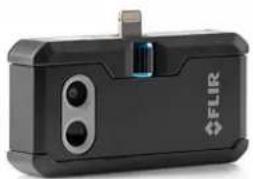
natural_image
Black FLIR device with two ports and a clip (no visible text or symbols)1969: Thermovision Model 661. The camera 2015: FLIR One, an accessory to iPhone and An-weighed approximately 25 kg (55 lb.), the oscillo-droid mobile phones. Weight: 36 g (1.3 oz.). scope 20 kg (44 lb.), and the tripod 15 kg (33 lb.). The operator also needed a 220 VAC generator set, and a 10 L (2.6 US gallon) jar with liquid nitrogen. To the left of the oscilloscope the Polaroid attachment (6 kg (13 lb.)) can be seen.
FLIR Systems manufactures all vital mechanical and electronic components of the camera systems itself. From detector design and manufacturing, to lenses and system electronics, to final testing and calibration, all production steps are carried out and supervised by our own engineers. The in-depth expertise of these infrared specialists ensures the accuracy and reliability of all vital components that are assembled into your infrared camera.
28.1 More than just an infrared camera
At FLIR Systems we recognize that our job is to go beyond just producing the best infrared camera systems. We are committed to enabling all users of our infrared camera systems to work more productively by providing them with the most powerful camera-software combination. Especially tailored software for predictive maintenance, R & D, and process monitoring is developed in-house. Most software is available in a wide variety of languages.
We support all our infrared cameras with a wide variety of accessories to adapt your equipment to the most demanding infrared applications.
28.2 Sharing our knowledge
Although our cameras are designed to be very user-friendly, there is a lot more to thermography than just knowing how to handle a camera. Therefore, FLIR Systems has founded the Infrared Training Center (ITC), a separate business unit, that provides certified training courses. Attending one of the ITC courses will give you a truly hands-on learning experience.
The staff of the ITC are also there to provide you with any application support you may need in putting infrared theory into practice.
28.3 Supporting our customers
FLIR Systems operates a worldwide service network to keep your camera running at all times. If you discover a problem with your camera, local service centers have all the equipment and expertise to solve it within the shortest possible time. Therefore, there is no need to send your camera to the other side of the world or to talk to someone who does not speak your language.
Website
http://www.flir.com
Customer support
http://support.flir.com
Copyright
© 2023, FLIR Systems, Inc. All rights reserved worldwide.
Disclaimer
Specifications subject to change without further notice. Models and accessories subject to regional market considerations. License procedures may apply. Products described herein may be subject to US Export Regulations. Please refer to exportquestions@flir.com with any questions.

- User's manual FLIR Exx series
- Important note
- Důležitá poznámka
- Safety information ....2
- Notice to user 6
- Customer help 8
- Quick start guide ....9
- Camera overview.... 11
- Handling the camera.... 22
- Saving and working with images 58
- Cloud connectivity.... 63
- Working with the image archive.... 66
- Achieving a good image 69
- Working with image modes.... 77
- Working with measurement tools 79
- Working with color alarms and isotherms.... 87
- Annotating images 90
- Programming the camera (time-lapse) 94
- Recording video clips 95
- Inspection Route 96
- Screening alarm 105
- Configuring Wi-Fi 107
- Pairing Bluetooth devices.... 108
- Fetching data from external FLIR meters 109
- Camera settings 111
- Cleaning the camera 116
- Mechanical drawings 118
- Declaration of conformity 120
- About calibration.... 121
- About FLIR Systems 124
- 1
- Disclaimers
- Legal disclaimer
- U.S. Government Regulations
- Patents
- Quality assurance
- Third-party licenses
- Usage statistics
- Copyright
- Online documentation
- Register your camera
- Accuracy
- Calibration
- Training
- Important note about this manual
- Note about authoritative versions
- Disposal of electronic waste
- 4
- Customer help
- General
- Submitting a question
- Downloads
- Quick start guide
- Follow this procedure:
- To keep in mind
- Laser distance meter and laser pointer
- Laser transmitter and receiver
- Difference in position
- Laser warning label
- Laser rules and regulations
- Screen elements
- General
- Menu system
- Swipe-down menu
- Image overlay information
- Navigating the menu system
- Navigating using the navigation pad
- 7
- Handling the camera
- Charging the battery
- General
- Using the stand-alone battery charger to charge the battery
- Stand-alone battery charger LED indicator
- Using the USB battery charger to charge the battery
- Charging the battery using a USB cable connected to a computer
- Note
- Removing the battery
- Turning on and turning off the camera
- Adjusting the thermal camera focus
- Manual focus
- Autofocus
- Autofocus method
- WARNING
- Continuous autofocus
- Operating the laser distance meter
- General
- Procedure
- Measuring areas
- General
- Procedure
- Connecting external devices and storage media
- Moving files to a computer
- Related topics
- Programmable button
- Programmable button options
- Using the camera lamp as a flash
- Hand strap
- Mounting the hand strap
- Wrist strap
- Front protection
- Changing camera lenses
- Calibrating the lens-camera combination
- Introduction
- AutoCal procedure
- Calibrating the compass
- About image files
- General
- File-naming convention
- Storage capacity
- About UltraMax
- Saving an image
- Previewing an image
- Opening a saved image
- Editing a saved image
- Related topics
- Displaying the image information
- Zooming an image
- Deleting images
- Resetting the image counter
- Uploading to FLIR Ignite
- Connecting to internet
- Connecting to Wi-Fi
- Connecting via Bluetooth
- Creating a FLIR Ignite account
- Pairing with FLIR Ignite
- Automatic upload
- Manual upload
- Uploading an image/video file
- Uploading multiple files
- Uploading folders
- Accessing FLIR Ignite
- Working with the image archive
- General
- Opening image and video files
- Creating a new folder
- Renaming a folder
- Changing the active folder
- Moving files between folders
- Uploading files and folders
- Deleting a folder
- Deleting an image or video file
- Deleting multiple files
- Deleting all files
- General
- Adjusting the infrared camera focus
- Manual focus
- Autofocus
- Continuous autofocus
- Adjusting the infrared image
- General
- Example 1
- Example 2
- Auto adjustment region
- Manual adjustment by touching the screen
- General
- Procedure
- Auto-adjusting the image in manual mode
- Locking the touch screen
- Manual adjustment by using the navigation pad
- Manual adjustment modes
- Manual adjustment in Level, Span mode
- Manual adjustment in Level, Max, Min mode
- Changing the camera temperature range
- Changing the color palettes
- Changing the measurement parameters
- Performing a non-uniformity correction (NUC)
- General
- Performing an NUC manually
- Hiding all overlay
- 12
- Working with image modes
- General
- Image examples
- Selecting an image mode
- Working with measurement tools
- General
- Adding/removing measurement tools
- Editing user presets
- Moving and resizing a measurement tool
- General
- Moving a spot
- Moving and resizing a box or circle tool
- Changing the measurement parameters
- General
- Types of parameters
- Recommended values
- Procedure
- Setting global parameters
- Changing local parameters
- Displaying values in the result table
- Creating and setting up a difference calculation
- Setting a measurement alarm
- General
- Types of alarm
- Alarm signals
- Procedure
- Setting up an alarm for a spot
- Setting up an alarm for a box or circle
- Setting up an alarm for a difference calculation
- Working with color alarms and isotherms
- Color alarms
- Setting up above, below, and interval alarms
- Building isotherms
- About the Condensation alarm
- About the Insulation alarm
- Setting up condensation and insulation alarms
- General
- Adding a note
- Adding a text comment table
- Creating a text comment table template
- Manually creating a table template
- Example mark-up structure
- Adding a voice annotation
- Adding a sketch
- Programming the camera (time-lapse)
- Recording video clips
- General
- Recording a video clip
- Playing a saved video clip
- Inspection Route
- General
- FLIR Inspection Route Solution user manual
- User interface
- Drop-down menu
- Inspection list
- Performing an inspection
- Preparation
- Capturing inspection data
- Editing inspection point data
- Setting the status
- Deleting an image
- Adding a comment
- Saving an image
- Recording a video clip
- Viewing and editing inspection images
- Inspection list
- Adding an inspection point
- Transferring inspection results
- Upload results to FLIR Ignite
- Move results manually
- Remove results from camera
- Configuration
- Creating an inspection route
- Creating an inspection route in the camera
- Manually editing an XML file
- General
- Work flow
- Activate and configure the screening alarm
- Record reference samples
- Perform the screening
- Setting up a wireless access point
- Connecting the camera to Wi-Fi
- Pairing Bluetooth devices
- Fetching data from external FLIR meters
- General
- Technical support for external meters
- Procedure
- Typical moisture measurement and documentation procedure
- More information
- FLIR Ignite
- Recording mode
- Connections
- Camera temperature range
- Save options & storage
- Device settings
- Camera housing, cables, and other items
- CAUTION
- Infrared lens
- Infrared detector
- 25
- Mechanical drawings
- Declaration of conformity
- Introduction
- Definition—what is calibration?
- Camera calibration at FLIR Systems
- The differences between a calibration performed by a user and that performed directly at FLIR Systems
- Calibration, verification and adjustment
- Non-uniformity correction
- Thermal image adjustment (thermal tuning)
- About FLIR Systems
- More than just an infrared camera
- Sharing our knowledge
- Supporting our customers
- Website
- Customer support
- Copyright
- Disclaimer
Brand : FLIR
Model : E85
Category : Measurement