
CM94 - Measurement FLIR - Free user manual and instructions
Find the device manual for free CM94 FLIR in PDF.


| Product Type | Clamp Meter |
| Model | CM94 |
| Brand | FLIR |
| AC Current Range | 0.1 A to 600 A |
| DC Current Range | 0.1 A to 600 A |
| AC Voltage Range | 0.1 V to 600 V |
| DC Voltage Range | 0.1 V to 600 V |
| Resistance Range | 0.1 Ω to 60 MΩ |
| Capacitance Range | 1 nF to 4000 μF |
| Frequency Range | 1 Hz to 100 kHz |
| Temperature Measurement | −20°C to 1000°C (type K thermocouple) |
| Display | 4000-count LCD with backlight |
| Safety Rating | CAT III 600V |
| Power Supply | 2 × AA batteries |
| Dimensions | 240 mm × 80 mm × 45 mm |
| Weight | 350 g (including batteries) |
| Jaw Opening | 30 mm |
| Data Hold | Yes |
| Min/Max Recording | Yes |
| Auto Power Off | Yes (programmable) |
| Maintenance | Clean with dry cloth; avoid solvents; store in dry place |
| Spare Parts | Test leads, thermocouple, batteries (available from FLIR) |
Frequently Asked Questions - CM94 FLIR
User questions about CM94 FLIR
0 question about this device. Answer the ones you know or ask your own.
Ask a new question about this device
Download the instructions for your Measurement in PDF format for free! Find your manual CM94 - FLIR and take your electronic device back in hand. On this page are published all the documents necessary for the use of your device. CM94 by FLIR.
USER MANUAL CM94 FLIR
USER MANUAL True RMS AC/DC 2000A Utility Clamp Meter
Model CM94
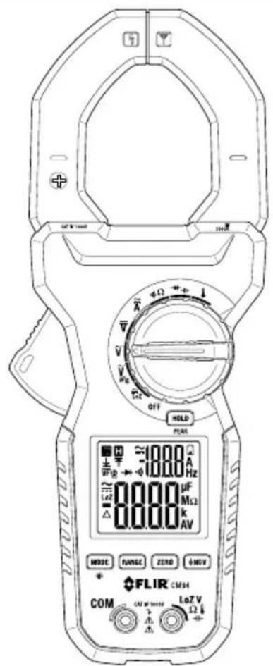

USER MANUAL True RMS AC/DC 2000A Utility Clamp Meter
Table of contents
1 Advisories....1
1.1 Copyright.... 1
1.2 Quality Assurance 1
1.3 Documentation 1
1.4 Disposal of Electronic Waste.... 1
2 Introduction....2
3 Safety ....3
3.1 General Safety Information 3
3.2 Safety Terms Used In This Manual 3
3.3 Warning and Caution Statements 3
3.4 International Electrical Symbols 5
3.5 CENELEC Directives.... 5
4 Descriptions ....6
4.1 Product Description.... 6
4.2 Control Button Descriptions 7
4.3 Rotary Switch Positions....7
4.4 Display Description 8
5 Meter Operation 9
5.1 Powering the Meter 9
5.2 Auto Power OFF (APO) 9
5.3 Automatic and Manual Ranges 9
5.4 Out-of-Range Alert.... 10
5.5 Display Hold Function.... 10
5.6 Display Backlight 10
5.7 AC and DC Voltage Measurements.... 10
5.8 LoZ Voltage Measurements 12
5.9 Low Pass Filter (VFD) AC Voltage Measurements 12
5.10 Current Clamp Measurements.... 13
5.11 Resistance Measurements 14
5.12 Continuity Measurements.... 15
5.13 Diode Measurements 16
5.14 Capacitance Measurements 18
5.15 Type-K Thermocouple Measurements 19
5.16 Non-Contact AC Voltage Detector 20
6 Maintenance.... 22
6.1 Cleaning.... 22
Table of contents
6.2 Battery Replacement.... 22
6.3 Meter Storage.... 22
7 Specifications.... 23
7.1 General Specifications.... 23
7.2 DC Voltage Specifications 24
7.3 LoZ (DC Voltage) Specifications.... 24
7.4 AC Voltage Specifications.... 24
7.5 LoZ (AC Voltage) Specifications.... 25
7.6 VFD (low pass filter) AC Voltage Specifications 25
7.7 PEAK HOLD Capture Mode Specifications.... 25
7.8 Resistance Specifications.... 25
7.9 Continuity Specifications 25
7.10 Capacitance Specifications.... 26
7.11 Diode Specifications 26
7.12 DC Current Specifications (Clamp) 26
7.13 AC Current Specifications (Clamp) 26
7.14 Hz Line Level Frequency Specifications.... 27
7.15 Temperature Specifications.... 27
7.16 Non-Contact AC Voltage Detector (NCV) 28
7.17 Input Specifications.... 28
7.18 Safety Specifications 28
8 Three-Year Warranty 29
9 Customer Support.... 30
9.1 Corporate Headquarters 30
1 Advisories
1.1 Copyright
©2021, FLIR Systems, Inc. All rights reserved worldwide. No parts of the software including source code may be reproduced, transmitted, transcribed or translated into any language or computer language in any form or by any means, electronic, magnetic, optical, manual or otherwise, without the prior written permission of FLIR Systems.
The documentation must not, in whole or part, be copied, photocopied, reproduced, translated or transmitted to any electronic medium or machine-readable form without prior consent, in writing, from FLIR Systems. Names and marks appearing on the products herein are either registered trademarks or trademarks of FLIR Systems and/or its subsidiaries. All other trademarks, trade names or company names referenced herein are used for identification only and are the property of their respective owners.
1.2 Quality Assurance
The Quality Management System under which these products are developed and manufactured has been certified in accordance with the ISO 9001 standard.
FLIR Systems is committed to a policy of continuous development; therefore, we reserve the right to make changes and improvements on any of the products without prior notice.
1.3 Documentation
To access the latest manuals and notifications, go to the Download tab at: https://support.flir.com. It only takes a few minutes to register online. In the download area you will also find the latest releases of manuals for our other products, as well as manuals for our historical and obsolete products.
1.4 Disposal of Electronic Waste

As with most electronic products, this equipment must be disposed of in an environmentally friendly way, and in accordance with existing regulations for electronic waste. Please contact your FLIR Systems representative for more details.
2 Introduction
The CM94 is a high accuracy, rugged measurement instrument intended for the electrical utility and industrial maintenance professional for inspecting and troubleshooting high voltage/current electrical infrastructure systems and equipment. The low input impedance mode (LoZ) helps determine whether a measured voltage is 'real' or induced by load carrying cables running adjacent and parallel to the measurement target (ghost voltage).
Visit https://www.support.flir.com/prodreg to register your CM94 and to read the three-year warranty text.
Features
• Primary 6000 count and secondary 1999 count dual backlit displays
- Dual display of ACA + Hz and ACV + Hz
• Rated CAT IV 1000V / 2000A
- True RMS sensing
- VFD-V and VFD-Hz for use with variable speed drives
• Non-contact voltage detection (NCV)
- PEAK mode captures Peak Min and Peak Max current/voltage in 5 millisecond window
• Data Hold and Relative/Zero modes
• Auto Power OFF (APO) in 34 minutes
- LoZ mode to help detect 'ghost' voltages
- Type-K thermocouple temperature measurements
• Large jaws accommodate 2.2 in. (55 mm) cables
3 Safety
3.1 General Safety Information
This user manual contains information and warnings that must be followed for operating the instrument safely and maintaining the instrument in a safe operating condition. If the instrument is used in a manner not specified by the manufacturer, the protection provided by the instrument may be impaired.
The meter protection rating, against the users, is double insulation per UL/IEC/EN61010-1 Ed. 3.0, IEC/EN61010-2-033 Ed. 1.0, CAN/CSA C22.2 No. 61010-1 Ed. 3.0, IEC/EN61010-2-032 Ed. 3.0 & IEC/EN61010-031 Ed. 1.1: Measurement Category IV 1000V AC & DC.
Per IEC61010-1 OVERVOLTAGE CATEGORY
OVERVOLTAGE CATEGORY II (CAT II) is for equipment intended to be supplied from the building wiring. It applies both to plug-connected equipment and to PERMANENTLY CONNECTED EQUIPMENT.
OVERVOLTAGE CATEGORY III (CAT III) is for equipment intended to form part of a building wiring installation. Such equipment includes socket outlets, fuse panels, and some MAINS installation control equipment.
OVERVOLTAGE CATEGORY IV (CAT IV) is for equipment installed at or near the origin of the electrical supply to a building, between the building entrance and the main distribution board. Such equipment may include electricity tariff meters and primary over-current protection devices.
3.2 Safety Terms Used In This Manual
WARNING: Identifies conditions and actions that could result in serious injury or even death to the user.
CAUTION: Identifies conditions and actions that could cause damage or malfunction in the instrument.
3.3 Warning and Caution Statements

WARNING
To reduce the risk of fire or electric shock, do not expose this product to rain or moisture. The meter is intended only for indoor use.

WARNING
To avoid electrical shock hazard, observe the proper safety precautions when working with voltages above 60 VDC or 30 VAC rms. These voltage levels pose a potential shock hazard to the user. Before and after hazardous voltage measurements, test the voltage function on a known source such as line voltage to determine proper meter functioning.

WARNING
Keep hands/fingers behind the hand/finger barriers (of the meter and the test leads) during measurement. Inspect test leads, connectors, and probes for damaged insulation or exposed metal before using the instrument. If any defects are found, replace them immediately. Use only the test leads provided with the equipment (or UL Listed probe assemblies rated CAT IV 1000V or better).

WARNING
The accompanied test probe assembly meets UL/IEC/EN61010-031 Ed. 1.1 to the same meter ratings or better. IEC 61010-031 requires exposed conductive test probe tips to be ≤ 4mm for CAT III & CAT IV ratings. Refer to the category markings on your probe assemblies as well as on the add-on accessories (detachable Caps or Alligator Clips, etc.), if any, for applicable rating changes.

WARNING
This Clamp meter is designed for clamping around or removing from non-insulated, hazardous live conductors. Nonetheless, individual protective equipment must be used when hazardous live parts in the installation, where the measurement is to be made, could be accessible.

WARNING
Remove test leads from the meter before taking clamp measurements.

CAUTION
Disconnect the test leads from the test points before changing meter functions.

CAUTION
Do not use the device for a procedure that it is not intended for. This can cause damage to the protection built into the instrument.
3.4 International Electrical Symbols
⚠ Caution! Refer to the explanation in the user manual.
Caution! Risk of electrical shock.
Earth ground.
Double/reinforced insulation.
Fuse.
\~ AC (alternating current).
DC (direct current).
Application around, and removal from, hazardous live conductors is permitted.
3.5 CENELEC Directives
This instrument conforms to CENELEC Low-voltage directive 2014/35/EC, Electromagnetic compatibility directive 2014/30/EU and RoHS directive 2011/65/EU.
4 Descriptions
4.1 Product Description

Figure 4.1 Product Description
- Non-Contact Voltage Detector (NCV) antenna
- Clamp jaws
- Conductor alignment icon
- Hand/finger barrier
- Jaw opening trigger
- Display
- RANGE button
- MODE /Display backlight button
- Negative (COM) input terminal
- Positive input terminal
- Non-Contact Voltage detector button
- ZERO /Relative mode button
- Battery compartment
- HOLD /PEAK button
- Rotary selector switch
4.2 Control Button Descriptions
| MODE | Short press to toggle AC/DC where necessary, to select an option at a multi-option rotary switch position, and to toggle °C and °F units in temperature measurement mode. |
| Long press to toggle the display backlight ON/OFF. | |
| RANGE | Short press to change to Manual range mode, subsequent presses will step through available ranges. Long press to return to the Auto range mode. |
| ZERO | Short press to engage the Relative mode where subsequent measurements are displayed relative to the measurement on the display at the time of the button press (the delta relative icon appears when the Relative mode is engaged). Long press to zero the display before taking a DC measurement. |
| ↓NCV | Short press to engage/disengage the Non-Contact Voltage Detection mode. |
| HOLD | Short press to freeze/unfreeze displayed readings. |
| PEAK | Long press to engage the PEAK mode. Short press to toggle between MAX (up arrow icon appears) and MIN (down arrow icon appears). Long press to exit the PEAK mode. |
4.3 Rotary Switch Positions
| OFF | Meter power is switched OFF. |
| Low Impedance mode. | |
| _VF D | AC Voltage mode with VFD (low pass filter). |
| AC Voltage mode. | |
| DC Voltage mode. | |
| Current mode (AC/DC). | |
| Continuity mode. | |
| Resistance mode. | |
| Diode mode. | |
| Capacitance mode. | |
| Thermocouple temperature measurement mode. |
4.4 Display Description

Figure 4.2 Display Description
- Auto Range
- Data hold
- Diode mode
- 1999 count secondary display
- Battery status
- Units of measure
- 6000 count primary display
- Relative mode
- Low impedance mode
- AC and DC measurement symbols
- Continuity function
- Low pass filter mode (VFD)
- Peak MAX (up arrow) and Peak MIN (down arrow)
5 Meter Operation
NOTE
Before operating the device, you must read, understand, and follow all instructions, dangers, warnings, cautions, and notes.
NOTE
When the meter is not in use, the function switch should be set to the OFF position.
NOTE
When connecting the probe leads to the device under test, connect the negative lead before connecting the positive lead. When removing the probe leads, remove the positive lead before removing the negative lead.
NOTE
Before and after hazardous voltage measurements, test the voltage function on a known source (such as line voltage) to determine proper meter functionality.
5.1 Powering the Meter
Set the function switch to any position to power the meter ON.
If the low battery voltage warning is displayed, or if the meter does not power ON, replace the batteries. See Section 6, Maintenance, for battery replacement details.
5.2 Auto Power OFF (APO)
The APO feature switches the meter OFF after approximately 34 minutes of inactivity. The meter will beep to alert you when it is about to power OFF, pre the MODE button to extend the APO time. If the meter powers OFF, turn the rotary switch to the OFF position first and then to an operational position to switch back ON.
5.3 Automatic and Manual Ranges
The meter uses automatic ranging by default. To manually select a measurement range, short press the RANGE button to exit the Auto mode. Subsequent, short presses will step through the available ranges. Long press the RANGE button to return to the Auto Range mode. When the Auto Range mode is active, the Auto Range symbol is displayed.

Figure 5.1 Auto Range Display Icon
5.4 Out-of-Range Alert
If the input is out-of-range, OL is displayed. Please do not attempt to make measurements beyond the specified ranges of the meter.
5.5 Display Hold Function
After taking a measurement, short press the HOLD button to freeze a reading. Press the HOLD button again to return to normal operation. The H icon will appear when the display hold function is engaged.
5.6 Display Backlight
Long press the backlight button to turn ON the display backlighting. Long press again to switch the backlight OFF. The backlight switches OFF automatically after approximately 25 seconds to conserve battery energy.
5.7 AC and DC Voltage Measurements

CAUTION
Use caution when the measured voltage is greater than 30V DC or AC rms.
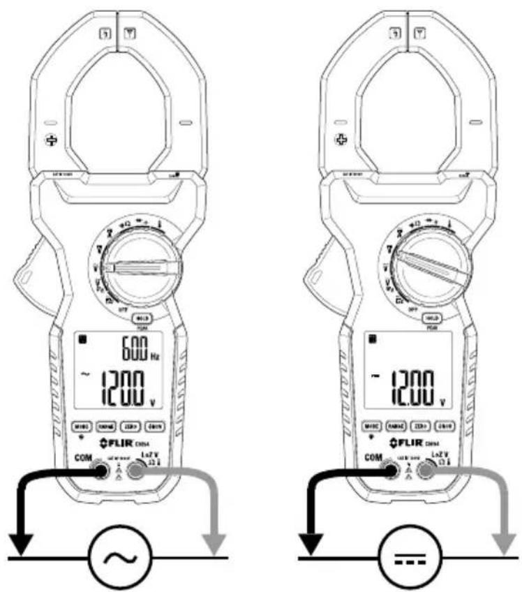
Figure 5.2 AC Voltage (left) and DC Voltage (right) Measurement Setups
- Set the function switch to the AC Voltage or DC Voltage position.
- Insert the black test lead into the negative (COM) terminal and the red test lead into the positive terminal.
- Place the probe ends of the test leads in parallel to the part under test.
- Read the Auto Range voltage measurement on the display.
- To switch to Manual Range mode, short press the RANGE button. Subsequent short presses of the RANGE button will step through the available ranges. Long press the RANGE button to return to Auto Range mode.
- Read the frequency (Hz) of an AC signal on the upper secondary display.
5.8 LoZ Voltage Measurements

WARNING
In LoZ mode, the input impedance increases quickly from the initial 2.5kΩ to a few hundred kΩ's on high voltage signals. Peak initial load current, while testing 1000 V AC for example, can be as high as 566 mA (1000 V x 1.414 / 2.5kΩ), decreasing to roughly 3.37 mA (1000 V x 1.414 / 420kΩ) within a fraction of a second. Do not use LoZ mode on circuits that could be damaged by such low input impedance. Use the standard high input impedance voltage modes to minimize loading on such circuits.

CAUTION
Use caution when the measured voltage is greater than 30V DC or AC rms.
LoZ Voltage measurements eliminate the affects of 'ghost' voltages. The procedure for taking LoZ Voltage measurements is essentially the same as for taking standard Voltage measurements, the only difference is that for LoZ Voltage measurements you select the LoZ rotary switch position and you must take into consideration the effect low impedance will have on circuitry that you test (read Warning statement above). Refer to the previous section for other Voltage measurement details.
When you turn the rotary dial to the LoZ position, the display will show 'auto' indicating that the CM94 will automatically detect the measured signal as AC or DC.
5.9 Low Pass Filter (VFD) AC Voltage Measurements

CAUTION
Use caution when the measured voltage is greater than 30V DC or AC rms.
Select the VFD mode using the rotary selector switch.
The VFD feature eliminates high frequency noise in AC voltage measurements by means of a low pass filter. The VFD mode is designed for variable frequency drive measurements. The VFD icon will appear on the display in this mode. The procedure for taking VFD Voltage measurements is identical to the procedure for taking standard Voltage measurements. Refer to the previous sections for Voltage measurement details.
5.10 Current Clamp Measurements

WARNING
Do not measure current on a circuit if the voltage increases to more than 1000 V. This can cause damage to the instrument and can cause injury to persons.

WARNING
Do not use the meter to measure current above the rated frequency. This may cause the magnetic circuits in the jaws to reach hazardous temperatures.

WARNING
Disconnect the test leads from the meter before taking Clamp measurements.
Clamp Measurement Considerations
- Press the jaw trigger to open the jaws and then clamp around the conductor(s) of only one pole of a circuit.
- Ensure that the jaws are completely closed. Enclosing conductor(s) of more than one pole of a circuit may result in differential current measurements.
- Align the conductor(s) to the jaws using the conductor align icons on the clamp jaws.
- Adjacent current-carrying devices such as transformers, motors and conductor wires may affect measurement accuracy.
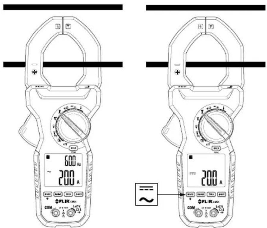
Figure 5.3 AC Current (left) and DC Current (right) Measurement Setups
Taking AC or DC Current Clamp Measurements
- Set the function switch to the Ampere position
- Short press the MODE button to select AC or DC current mode.
- For DC current mode, with no conductor in the clamp, long press the ZERO button to zero the display.
- Press the trigger to open the clamp jaws and clamp around the conductor under test.
- Read the Auto Range current measurement on the display.
- To switch to Manual Range mode, short press the RANGE button. Subsequent short presses of the RANGE button will step through the available ranges. Long press the RANGE button to return to Auto Range mode.
- Read the frequency (Hz) of an AC signal on the upper secondary display.
5.11 Resistance Measurements

WARNING
Do not perform resistance tests before removing the power to resistors and other devices under test. Injury to persons can occur.
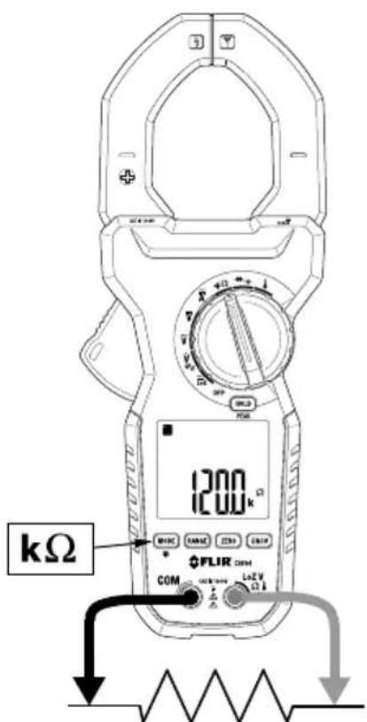
Figure 5.4 Resistance Measurement Setup.
- Set the function switch to the Resistance position.
- If necessary, short press the MODE button to select the Resistance function.
- Insert the black test lead into the negative (COM) terminal and the red test lead into the positive terminal.
- Place the probe ends of the test leads in parallel to the part under test.
- Read the resistance value on the display.
- To switch to Manual Range mode, short press the RANGE button. Subsequent short presses of the RANGE button will step through the available ranges. Long press the RANGE button to return to Auto Range mode.
5.12 Continuity Measurements

WARNING
Do not perform continuity tests before removing power to the device under test. Injury to persons can occur.

Figure 5.5 Continuity Measurements. Note the CLOSED (0.00) and OPEN (OL) circuit examples.
- Set the function switch to the Continuity position.
- If necessary, short press the MODE button to select the Continuity function.
- Insert the black test lead into the negative (COM) terminal and the red test lead into the positive terminal.
- Place the probe ends of the test leads in parallel to the part under test.
- If the measurement is < 10 , the meter will beep. If the measurement is >200 , the meter will not beep. Between 10 and 200 , the meter will stop beeping at an unspecified point.
5.13 Diode Measurements

WARNING
Do not perform diode tests before removing power to the diode under test. Injury to persons can occur.

Figure 5.6 Diode Testing. Note the two test positions, forward and reverse bias.
- Set the function switch to the Diode position.
- If necessary, short press the MODE button to select the Diode function.
- Insert the black test lead into the negative (COM) terminal and the red test lead into the positive terminal.
- Take two measurements, one forward biased and one reverse biased. This can be accomplished by, first, placing the probe ends of the test leads in parallel to the part under test in one direction and then taking a second measurement with the test leads reversed.
- If the reading is between 0.40 V and 0.90 V in one direction and OL (overload) in the opposite direction, the component is good. If the measurement is 0V in both directions (shorted) or OL is displayed in both directions (open), the component is bad.
5.14 Capacitance Measurements

WARNING
Do not perform capacitance tests before removing power to the capacitor under test and discharging it through an appropriate resistance load. Injury to persons can occur.
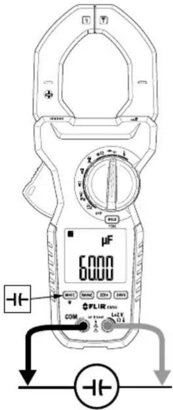
Figure 5.7 Capacitance Measurement Setup.
- Set the function switch to the Capacitance position.
- If necessary, short press the MODE button to select the Capacitance function.
- Insert the black test lead into the negative (COM) terminal and the red test lead into the positive terminal.
- Place the probe ends of the test leads in parallel to the part under test.
- Read the capacitance value on the display.
- To switch to Manual Range mode, short press the RANGE button. Subsequent short presses of the RANGE button will step through the available ranges. Long press the RANGE button to return to Auto Range mode.
5.15 Type-K Thermocouple Measurements

CAUTION
The supplied thermocouple is rated for -4 \~ 482°F (-20 \~ 250°C) only, it is not rated for the entire specified temperature range of the meter.
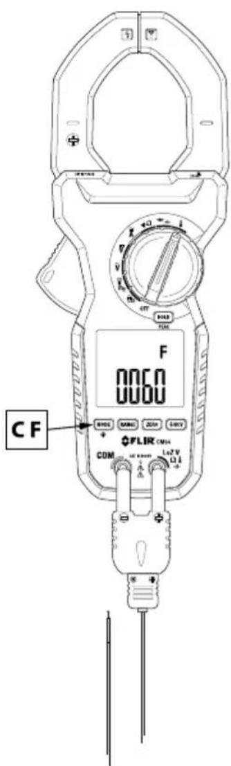
Figure 5.8 Thermocouple Temperature Measurements.
-
Set the function switch to the Temperature position.
-
Insert the banana plug Type-K temperature probe into the meter's input terminals observing correct polarity. A plug adapter with banana plug to Type-K socket (to adapt to other Type-K standard mini plug temperature probes) can be obtained optionally.
-
Touch the thermocouple probe tip to the surface of an object under test or hold the probe in air.
-
Read the temperature measurement on the display.
-
Use the MODE button to toggle °C and °F units of measure.
5.16 Non-Contact AC Voltage Detector

CAUTION
Use caution when the measured voltage is greater than 30V DC or AC rms.

Figure 5.9 Non-Contact AC Voltage Detection (NCV).
-
Set the function switch to the AC Voltage position and remove the test leads from the CM94.
-
Short press the NCV button. The display will show the EF symbol (electromotive force).
-
The voltage detection antenna is located at the tip of the clamp jaws, just to the right of the jaw opening seam (with the meter facing you).
- Hold the CM94 with hand/fingers behind the safety barrier and place the antenna near the source of potential voltage. Leave the jaws closed while using the voltage detector.
- If voltage is present, the meter will beep and display dashes. The higher the voltage, the higher the beep rate and the higher the number of displayed dashes (1, 3, or 5 dashes).
6 Maintenance
6.1 Cleaning
With the CM94 OFF, wipe the meter housing with a damp cloth as needed. Do not use abrasives or solvents. Dry completely before use.
6.2 Battery Replacement
The battery compartment is located on the back of the CM94 secured by two screws. Open the compartment and replace the two 'AA' batteries observing correct polarity. Please secure the battery compartment before using the meter.
6.3 Meter Storage
If the meter is to be stored for an extended period, please remove the batteries and store separately.
7 Specifications
7.1 General Specifications
| Display Primary: 6000 count backlit LCD | Secondary: 1999 count backlit LCD |
| Polarity Automatic | |
| Update rate 5 readings per second, nominal | |
| Operating temperature 14 ~ 122°F (-10 ~ 50°C) | |
| Relative humidity Maximum relative humidity | 80% for temperature up to 88°F (31°C) decreasing linearly to 50% relative humidity at 122°F (50°C) |
| Pollution Degree 2 | |
| Storage temperature -4 ~ 140°F (-20 ~ 60°C) < 80% RH (with battery removed) | |
| Operating altitude 7000 ft. (2000 m) maximum | |
| Temperature coefficient Nominal 0.15 x (specified accuracy)/ °C @ (0 ~ 18°C [32 ~ 64.4°F] or 28 ~ 40°C [82.4 ~ 104°F]), or as otherwise specified | |
| Sensing True RMS | |
| Transient protection | 12 kV (1.2/50μs surge) |
| Overload Protection Current Clamp measurements: 2000A DC/ AC rms continuous Voltage functions (input terminals): 1100V DC/AC rms Other functions (input terminals): 1000V DC/AC rms | |
| Power supply | 1.5 V 'AA' battery x 2 |
| Power consumption | 14 mA for Current functions; 5.2 mA for other functions |
| Low battery | < 2.4 V, approximately |
| APO timer | After 34 minutes of inactivity, approximately |
| APO consumption | 10μA, typical |
| DimensionsWeight 700 g (24.7 oz.) | (LxWxH): 269 x 106 x 51 mm (10.6 x 42 x 2.0 in.) |
| Jaw opening/Conductor diameter 55 mm | (2.2 in.) maximum |
| Electrical specification accuracy ± (% reading + number of digits) or as otherwise specified, at 73.4°F (23°C) ± 9°F (5°C). | |
| Accessories | Supplied: Test lead pair, Type-K thermocouple with banana-type connectors, printed Quick Start, and soft carrying pouOptional: Banana plug to Type K socket plug adaptor |
7.2 DC Voltage Specifications
| Range and Resolution Accuracy | |
| 6.000 V, 60.00 V, 600.0 V, & 1000 V ± | (0.5% + 5 digits) |
Input Impedance: 10MΩ, 50 pF nominal
7.3 LoZ (DC Voltage) Specifications
| Range and Resolution Accuracy | |
| 6.000 V, 60.00 V, 600.0 V, & 1000 V ± | (1.3% + 5 digits) |
LoZ DCV threshold: > 1.5 V DC, and < -1.5 V DC
Input impedance: Initially approx. 2.5k ohms, 600pF, nominal; Impedance increases within a fraction of a second as voltage increases above 50V (typical). Final impedance vs. displayed voltage: 10k ohms @100V, 60k ohms @300V, 200k ohms @600V, 420k ohms @1000V (typical)
7.4 AC Voltage Specifications
| Range and Resolution Frequency Accuracy | |
| 6.000 V, 60.00 V, 600.0 V1000 V | 80 Hz ~ 400 Hz ± (1.2% + 5 digits) |
Input Impedance: 10MΩ, 50 pF nominal
7.5 LoZ (AC Voltage) Specifications
| Range and Resolution Frequency Accuracy | |
| 6.000 V, 60.00 V, 600.0 V1000 V | 80 Hz ~ 60 Hz ± (1.5% + 5 digits) |
LoZ ACV threshold: > 1.5V AC, and < -1.5V AC
Input impedance: Initially approx. 2.5k ohms, 600pF, nominal; Impedance increases within a fraction of a second as voltage increases above 50V (typical). Final impedance vs. displayed voltage: 10k ohms @100V, 60k ohms @300V, 200k ohms @600V, 420k ohms @1000V (typical)
7.6 VFD (low pass filter) AC Voltage Specifications
| Range and Resolution Frequency Accuracy | 1 | |
| 6.000 V, 60.00 V, 600.0 V1000 V | 10 Hz ~ 20 Hz ± (4.0% + 80 digits) | 80 digits) |
| 20 Hz ~ 200 Hz ± (2.0% + 60 digits) | + 60 digits) | |
| 200 Hz ~ 400 Hz | ± (7.0% + 80 digits) | |
-
Not specified for fundamental frequency > 400 Hz
-
Accuracy linearly decreases from 2% + 60 digits @ 200 Hz to 7% + 80 digits @ 400 Hz
7.7 PEAK HOLD Capture Mode Specifications
Accuracy: Specified accuracy plus 250 digits for changes > 5ms in duration.
7.8 Resistance Specifications
| Range and Resolution Accuracy | |
| 600.0 Ω, 6.000 kΩ, 60.00 kΩ ± (0.5% + 5 digits) | |
| 600.0 kΩ | ± (0.8% + 5 digits) |
| 6.000 MΩ | ± (1.2% + 5 digits) |
| 40.00 MΩ | ± (2.3% + 5 digits) |
Open Circuit Voltage: 0.45 V DC, typical
7.9 Continuity Specifications
Audible threshold: 10Ω \~ 200Ω.
Beeper response time: 32ms, approx.
Beeper frequency: 2k Hz
7.10 Capacitance Specifications
| Range and Resolution Accuracy | 1 |
| 60.00 nF, 600.0 nF, 6.000 μF ± (2.0% + 5 digits) | |
| 60.00 μF, 600.0 μF ± (3.5% + 5 digits) | 2 |
| 2000 μF ± (4.0% + 5 digits) | 3 |
- Accuracy specified with film capacitor or better
- Temperature coefficient: 0.25 x (specified accuracy) / °C [1.8°F] @ (0 \~ 18°C [32 \~ 64.4°F] or 28 \~ 40°C [82.4 \~ 104°F])
- Temperature coefficient: 0.25 x (specified accuracy) / °C [1.8°F] @ (0 \~ 18°C [32 \~ 64.4°F] or 28 \~ 40°C [82.4 \~ 104°F])
7.11 Diode Specifications
| Range and Resolution Accuracy | |
| 1.000 V ± (1.0 + 3 digits) |
Test Current: 0.56 mA, typical
Open Circuit Voltage: < 1.8 V DC typical
7.12 DC Current Specifications (Clamp)
| Range and Resolution Accuracy | 12 |
| 200.0 A ± (2.0% + 5 digits) | |
| 0 ~ 500 A ± (2.0% + 5 digits) | |
| 500 ~ 2000 A ± (3.0% + 5 digits) |
- Induced error from adjacent current-carrying conductors: < 0.1 A/A
- Accuracy specified with DC Zero (Relative) mode applied to offset non-zero residual readings
7.13 AC Current Specifications (Clamp)
| Range and Resolution | Frequency | Accuracy |
| 200.0 A | 50 ~ 60 Hz | ± (2.0% + 5 digits) |
| 0 ~ 500 A | ± (2.5% + 5 digits) | |
| 500 ~ 2000 A | ± (3.0% + 5 digits) | |
| 200.0 A | 40 Hz ~ 50 Hz and 60 Hz~ | ± (2.5% + 5 digits) |
| 0 ~ 500 A ± (3.0% + 5 digits) | ||
| 500 ~ 1000 A ± (3.5% + 5 digits) | ||
| 1000 ~ 2000 A Unspecified |
- Induced error from adjacent current-carrying conductors: < 0.1 A/A
True RMS crest factor < 1.4 : 1 at full scale and < 2.8 : 1 at half scale.
7.14 Hz Line Level Frequency Specifications
| Range/Function Sensitivity (sine RMS) Frequency Range | |
| 6 V 2 V | |
| 60 V 20 V | |
| 600 V 100 V | |
| 1000 V | 600 V |
| 200 A 10 A | |
| 2000 A | 40 A |
| 6 V (VFD) | 1 V ~ 2 V |
| 60 V (VFD) | 6 V ~ 20 V |
| 600 V (VFD) | 60 V ~ 200 V |
- VFD sensitivity linearly decreases from 10% F.S. @ 200Hz to 40% F.S. @ 400Hz
- VFD sensitivity linearly decreases from 10% F.S. @ 200Hz to 40% F.S. @ 400Hz
- VFD sensitivity linearly decreases from 10% F.S. @ 200Hz to 40% F.S. @ 400Hz
Accuracy: ± (0.1% + 4 digits)
7.15 Temperature Specifications
| Range1 | Accuracy2 |
| -50 ~ 1000°C | ± (0.3% + 4 digits) |
| -58 ~ 1832°F | ± (0.3% + 6 digits) |
- Supplied thermocouple is rated for -4 482^ ( -20 250^ ) only, and therefore not rated for the entire specified temperature range of the meter.
- Assumes meter interior and ambient temperature have reached stable isothermal stage for correct junction voltage compensation. Does not include error introduced by thermocouple probe.
7.16 Non-Contact AC Voltage Detector (NCV)
| Typical Voltage Tolerance | Bar Graph Indication | |
| 40 V 10 V ~ 90 V 1 dash | ( — ) | |
| 100 V 64 V ~ 162 V 3 dashes | ( — — — ) | |
| 165 V 125 V ~ 1000 V 5 | dashes ( — — — — — ) |
7.17 Input Specifications
| Function Overload Protection | |
| Voltage, Current 1100V DC/AC RMS | |
| Resistance, Temperature, Diode, LoZ 1000V DC/AC RMS | |
7.18 Safety Specifications
| General Safety CE/EN/UL/CSA/RCM 61010 | |
| Category ratings | CAT IV 1000V AC/DC |
| Environmental Safety | REACH Regulation EC 1907/2006RoHS2 Directive 2011/65/ECWEEE Directive 2012/19/EC |
| Drop-proof | Designed to 6.6 ft. (2 m) |
| EMC | EN 61326-1:2006 (EN 55022, EN 61000-3-2, EN 61000-3-3, EN 61000-4-2, EN 61000-4-3, EN 61000-4-4, EN 61000-4-5, EN 61000-4-6, EN 61000-4-8, EN 61000-4-11) |
8 Three-Year Warranty
Please register your product within 60 days of purchase. Register your product at https://support.flir.com/prodreg or use the QR Code. Read the warranty text at the links provided.

Figure 8.1 Product Registration QR Code
9 Customer Support
Repair, Calibration, and Technical Support: https://support.flir.com.
9.1 Corporate Headquarters
FLIR Systems, Inc.
27700 SW Parkway Avenue
Wilsonville, OR 97070 USA
Website
http://www.flir.com
Customer support
http://support.flir.com
Copyright
© 2021, FLIR Systems, Inc. All rights reserved worldwide.
Disclaimer
Specifications subject to change without further notice. Models and accessories subject to regional market considerations. License procedures may apply. Products described herein may be subject to US Export Regulations. Please refer to exportquestions@flir.com with any questions.


- USER MANUAL True RMS AC/DC 2000A Utility Clamp Meter
- Table of contents
- Advisories....1
- Introduction....2
- Safety ....3
- Descriptions ....6
- Meter Operation 9
- Maintenance.... 22
- Specifications.... 23
- Three-Year Warranty 29
- Customer Support.... 30
- Advisories
- Copyright
- Quality Assurance
- Documentation
- Disposal of Electronic Waste
- Introduction
- Features
- Safety
- General Safety Information
- Safety Terms Used In This Manual
- Warning and Caution Statements
- WARNING
- CAUTION
- International Electrical Symbols
- CENELEC Directives
- Descriptions
- Product Description
- Display Description
- Meter Operation
- NOTE
- Powering the Meter
- Auto Power OFF (APO)
- Automatic and Manual Ranges
- Out-of-Range Alert
- Display Hold Function
- Display Backlight
- AC and DC Voltage Measurements
- LoZ Voltage Measurements
- Low Pass Filter (VFD) AC Voltage Measurements
- Current Clamp Measurements
- Clamp Measurement Considerations
- Taking AC or DC Current Clamp Measurements
- Resistance Measurements
- Continuity Measurements
- Diode Measurements
- Capacitance Measurements
- Type-K Thermocouple Measurements
- Non-Contact AC Voltage Detector
- Maintenance
- Cleaning
- Battery Replacement
- Meter Storage
- Specifications
- DC Voltage Specifications
- LoZ (DC Voltage) Specifications
- AC Voltage Specifications
- PEAK HOLD Capture Mode Specifications
- Continuity Specifications
- Capacitance Specifications
- Diode Specifications
- DC Current Specifications (Clamp)
- AC Current Specifications (Clamp)
- Hz Line Level Frequency Specifications
- Temperature Specifications
- Three-Year Warranty
- Customer Support
- Corporate Headquarters
- Website
- Customer support
- Copyright
- Disclaimer
Brand : FLIR
Model : CM94
Category : Measurement