
Elara FR-345 - Measurement FLIR - Free user manual and instructions
Find the device manual for free Elara FR-345 FLIR in PDF.


| Brand | FLIR |
| Model | Elara FR-345 |
| Product Type | Thermal Camera |
| Measurement Category | Meter |
| Dimensions (HxWxD) | 200 x 75 x 45 mm |
| Weight | 350 g |
| Power Supply | Rechargeable Li-ion battery, 3.7V, 2600 mAh |
| Charging Interface | USB-C |
| Display | 3.5-inch color LCD touchscreen |
| Thermal Resolution | 240 x 180 pixels |
| Temperature Range | -20°C to 550°C |
| Accuracy | ±2°C or ±2% of reading |
| Field of View | 35° x 26° |
| Image Capture | JPEG, Radiometric JPEG |
| Video Recording | MP4 with temperature data |
| Storage | MicroSD card (up to 32 GB) |
| Connectivity | Wi-Fi, USB-C, Bluetooth |
| Laser Class | Class 2, <1 mW at 630-670 nm |
| IP Rating | IP54 (dust and splash resistant) |
| Operating Temperature | -10°C to 50°C |
| Care & Cleaning | Clean lens with soft cloth; avoid solvents; store in case |
| Safety | Avoid direct eye exposure to laser; do not disassemble |
| Spare Parts | Replacement battery, USB cable, lens cap, carrying case |
| Repairability | Battery and SD card user-replaceable; other repairs by FLIR |
| Warranty | 2 years |
Frequently Asked Questions - Elara FR-345 FLIR
User questions about Elara FR-345 FLIR
0 question about this device. Answer the ones you know or ask your own.
Ask a new question about this device
Download the instructions for your Measurement in PDF format for free! Find your manual Elara FR-345 - FLIR and take your electronic device back in hand. On this page are published all the documents necessary for the use of your device. Elara FR-345 by FLIR.
USER MANUAL Elara FR-345 FLIR
Installation and User Guide
Elara™ FR-345-EST Camera

natural_image
Exterior view of a FLIR-based optical sensor device with hexagonal frame and mounting flange (no text or symbols on body)© 2021 FLIR Systems, Inc. All rights reserved worldwide. No parts of this manual, in whole or in part, may be copied, photocopied, translated, or transmitted to any electronic medium or machine readable form without the prior written permission of FLIR Systems, Inc..
Names and marks appearing on the products herein are either registered trademarks or trademarks of FLIR Systems, Inc. and/or its subsidiaries. All other trademarks, trade names, or company names referenced herein are used for identification only and are the property of their respective owners.
This product is protected by patents, design patents, patents pending, or design patents pending.
Photographs and images appearing in this manual may have been modified for illustrative purposes using commercial image editing software and may not always reflect an actual product configuration.
The contents of this document are subject to change without notice.
For additional information visit www.flir.com or write to FLIR Systems, Inc.
FLIR Systems, Inc.
6769 Hollister Avenue
Goleta, CA 93117
Support: https://support.flir.com/
Important Instructions and Notices to the User:
This device complies with part 15 of the FCC Rules. Operation is subject to the following two conditions: (1) This device may not cause harmful interference, and (2) this device must accept any interference received, including interference that may cause undesired operation.
Modification of this device without the express authorization of FLIR Systems, Inc. may void the user's authority under FCC rules to operate this device.
Note 1: This equipment has been tested and found to comply with the limits for a Class A digital device, pursuant to part 15 of the FCC Rules. These limits are designed to provide reasonable protection against harmful interference when the equipment is operated in a commercial environment. This equipment generates, uses, and can radiate radio frequency energy and, if not installed and used in accordance with the instruction manual, may cause harmful interference to radio communications. Operation of this equipment in a residential area is likely to cause harmful interference in which case the user will be required to correct the interference at the user's own expense.
Note 2: If this equipment came with shielded cables, it was tested for compliance with the FCC limits for a Class A digital device using shielded cables and therefore shielded cables must be used with the device.
Industry Canada Notice:
This Class A digital apparatus complies with Canadian ICES-003.
Proper Disposal of Electrical and Electronic Equipment (EEE)

The European Union (EU) has enacted Waste Electrical and Electronic Equipment Directive 2012/19/EU (WEEE), which aims to prevent EEE waste from arising; to encourage reuse, recycling, and recovery of EEE waste; and to promote environmental responsibility.
In accordance with these regulations, all EEE products labeled with the “crossed out wheeled bin” either on the product itself or in the product literature must not be disposed of in regular rubbish bins, mixed with regular household or other commercial waste, or by other regular municipal waste collection means. Instead, and in order to prevent possible harm to the environment or human health, all EEE products (including any cables that came with the product) should be
Document History
| Revision | Date | Comment |
| 100 | December 2020 | Initial FLIR release |
| 110 | May 2021 | Clarified behavior of navigating away from certain View settings menu pages after making changes and not saving them; changes to Intended Use Statement; changed FLIR Support URL |
Product Registration and Warranty Information
Register your Product with FLIR at https://customer.flir.com.
For warranty information, see https://www.flir.com/support-center/warranty/security/flir-security-product-warranties/.
Table of Contents
1. Camera Overview .... 1
1.1 Accessing Product Information from the FLIR Website 2
1.2 Camera Dimensions 3
1.3 Camera Specifications 3
2. Installation 5
2.1 Supplied Components 5
2.2 Site Preparation 5
2.3 Hardware Description 7
2.4 Supplying Power to the Camera 8
2.5 Initial Configuration 9
2.5.1 Connect the Camera 9
2.5.2 Discover the Camera and Configure for Networking 10
2.6 Mount and Connect the Camera 11
2.7 Aim and Boresight the Camera 12
2.8 Additional Configuration 13
2.9 Attach the Camera to a Supported VMS 14
3. Operation 15
3.1 Accessing the Camera 15
3.2 View Settings Home Page 15
3.3 Video Page 16
3.4 Visible Page 18
3.5 Thermal Page 22
3.6 Input/Output (I/O) Page 24
3.7 Screening Page 25
3.8 OSD Page 29
3.9 Georeference Page 29
3.10 Full-Screen Mode 30
4. Configuration 32
4.1 Network Page 32
4.2 Date & Time Page 33
4.3 Users Page 34
4.4 Alarm Page 35
4.5 I/O Devices Page 36
4.6 Cyber Page 37
4.6.1 Certificates 37
4.6.2 802.1x 39
Table of Contents
4.6.3 TLS/HTTPS 39
4.6.4 Services 39
4.7 Boresight Page 40
4.8 Firmware & Info Page 41
5. Maintenance and Troubleshooting Tips 43
5.1 Cleaning 43
5.2 Troubleshooting 43
1 Camera Overview
The FLIR Elara FR-345-EST is an affordable, fixed-mount radiometric camera for accurately measuring skin temperature* at medium- to high-throughput entry control points. Equipped with on-edge, intelligent face detection, Elara FR-345-EST issues on-screen prompts to individuals when they need to remove eyeglasses, while also guiding them to the correct position for best measurement. The non-contact camera automatically locates and measures the inner canthus (corner of the eye) within one second and provides an instant pass/fail graphic to the individual. Integration with VMS systems further streamlines workflow and decision-making for facilities, while helping security personnel maintain a safe distance from potential health risks.
For answers to frequently asked questions about using thermal imaging for elevated skin temperature (EST) screening, see this page on FLIR.com.
The Elara FR-345-EST camera includes a thermal sensor; a Full HD 1080p visible light camera; and digital I/O. When the camera is connected to an IP network, it functions as a server, providing services such as camera control, video streaming, and network communications. The server uses an open, standards-based communication protocol to communicate with FLIR and third-party video management system (VMS) clients, including systems that are compatible with ONVIF®. These clients can be used to control the camera and stream video during day-to-day operations. For a list of supported VMS clients, refer to the product's web page on FLIR.com. The video from the camera is viewed by streaming it over an IP network using H.264 and MJPEG encoding.
If help is needed during the installation process, contact the local FLIR service representative or call the support number that appears on the product's page at https://support.flir.com/. All installers and integrators are encouraged to take advantage of the training offered by FLIR; visit https://www.flir.com/support-center/training/ for more information.
For safety, and to achieve the highest levels of performance from the camera system, always follow the warnings and cautions in this manual when handling and operating the camera.
* DISCLAIMER: Contagions such as COVID-19, SARS, and other diseases can produce symptoms like elevated skin temperature—a possible sign of infection. While this FLIR camera is not capable of detecting or diagnosing viruses, it represent a simple, preliminary measure for mitigating further contagion and possible rebound, providing the confidence to return to normalcy.
Intended Use Statement
The FLIR EST line of cameras are intended for use as an adjunct to other clinical diagnostic procedures in the diagnosis, quantifying, and screening of differences in skin surface temperature changes. It can visualize and document temperature patterns and changes. The cameras may be used in public areas such as airports, train terminals, businesses, factories, and concerts. The FLIR EST cameras do not provide absolute measurement of temperature.
Related Documentation
• Elara FR-345-EST Quick Install Guide
• FLIR Security Cameras - Accessory Guide
• CB-WLBX-G4 Wall & Surface Mount Kit Installation Guide
• FLIR CGI Interface Description 2.1
• Nexus CGI WebSockets Manual
• FLIR Sensors SDK Programmer's Guide
1.1 Accessing Product Information from the FLIR Website
Up-to-date resources for the camera, including the FLIR Discovery Network Assistant (DNA) software tool — version 2.3.0.19 or higher — and this installation and user guide, are available from the camera's product information and support pages on FLIR.com.
To access product information from the FLIR website:
- Open FLIR.com and then select Products > Security > FLIR EST Thermal Screening Solutions.
![FLIR EST Thermal Screening Solutions SECURITY Thermal Security Cameras Counter UAS FLIR EST Thermal Screening Solutions Visible Security Cameras Video Management Systems Command and Control Software Encoders Servers, Storage & Clients People Flow Intelligence ALL Products [8] FLIR AS00-EST Fixed Mount FLIR EST™ Thermal Screening Solutions FLIR ES4-EST Handheld FLIR EST™ Thermal Screening Solutions FLIR E86-EST Handheld FLIR EST™ Thermal Screening Solutions Click the camera APPLICATIONS Plant Maintenance (6) Health & Safety (6) Critical Infrastructure (6) Life Sciences (6) Public Safety (6) FLIR ELANA™ FR-345-EST Intelligent Fixed-Mount Skin Temperature Screening FLIR TS40-EST Handheld FLIR EST™ Thermal Screening Solutions FLIR TS60-EST Handheld FLIR EST™ Thermal Screening Solutions](/content/2026/05/1094158/images/c8ef7b575df92b97df66f839b535cd219df1d501e14f84be51434c63511d4a69.jpg)
FLIR EST Thermal Screening Solutions Page on FLIR.com
- Find and click Elara FR-345-EST. The camera's product information page appears.
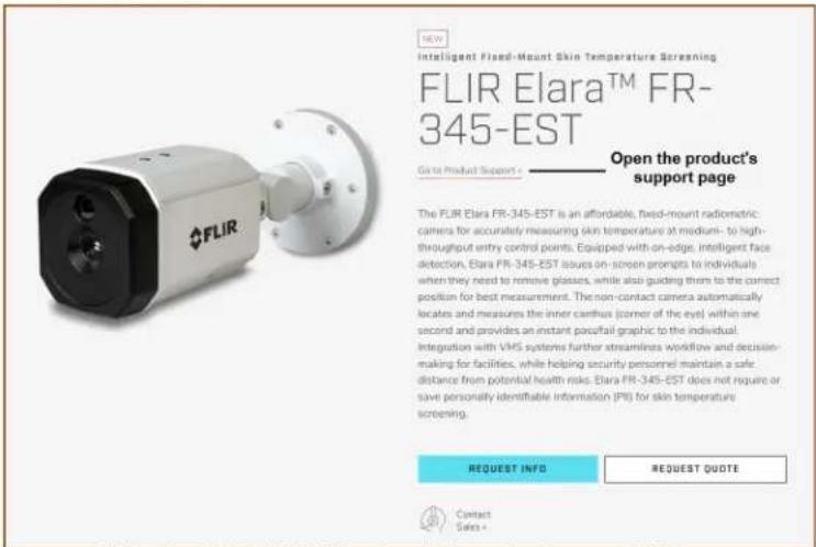
FLIR Elara FR-345-EST Product Information Page on FLIR.com
- To see more information, scroll down; for example, the camera's specifications, related documents, and accessories.
- Open the camera's support page. Click Go to Product Support.
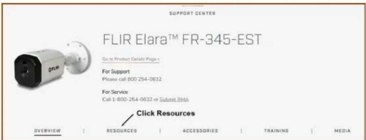
FLIR Elara FR-345-EST Product Support Page
- Click Resources.
- Download the resource you need. Click the relevant Download link.
1.2 Camera Dimensions
The Elara FR-345-EST camera's dimensions are:

Side View

Front View
1.3 Camera Specifications
| Thermal Sensor, Optics, and Optical Characteristics | Array Format | 320 x 256 |
| Sensor Technology | Long-Life, Uncooled VOx Microbolometer | |
| Pixel Pitch | 17 μm | |
| Frame Rate | 25 Hz | |
| FOV | 45° × 34° | |
| F/# | 1.5 | |
| Spectral Range | 7.5 μm to 13.5 μm | |
| Accuracy (Drift) in Screening Mode | ±0.5°C (±0.9°F) | |
| Object Temperature Range | 15°C to 45°C (59°F to 113°F); camera provides contrast from -20°C to 120°C (-4°F to 248°F) but will not provide temperature information | |
| Screening Mode Subject Distance | 1m ± 0.2m (39.4" ± 7.9") | |
| Video | Video Compression | Thermal: one channel of H.264 or MJPEGVisible: two independent channels of H.264 or MJPEG |
| Streaming Resolution | Thermal: upscaled to VGA (640 × 480) | |
| Visible: 1080p (1920 × 1080), 720p (1280 × 720), VGA (640 × 480) | ||
| System Integration | Ethernet | 10/100 Mbps |
| Network APIs | FLIR SDK; FLIR CGI; ONVIF Profile S | |
| Digital I/O | Input: one dry alarm contactOutput: one photo relay contact 1A max at 24 VAC/30 VDC | |
| Network | Supported Protocols | IPV4, HTTP, HTTPS, UPnP, DNS, NTP, RTSP, RTP, TCP, UDP, ICMP, IGMP, DHCP, ARP, IEEE 802.1X |
| General | Input Voltage | 12-30 VDC (±10%)24 VAC (21-28 VAC)802.3at (PoE+) |
| Power Consumption | 17 W | |
| Environmental | IP Rating (Dust & Water Ingress) | IP54 |
| Operating Temperature Range | 15°C to 45°C (60°F to 110°F) | |
| Storage Temperature Range | -40°C to 70°C (-40°F to 158°F) | |
| Humidity | 0-95% relative | |
| Vandalism | IK10 | |
| Compliance & Certifications | FCC Part 15 (Subpart B, class A); CE Marked; RoHS; WEEE; ONVIF Profile S | |
| Visible Light Camera | Sensor Type | 1920 x 1080 |
| Lens FOV | HFOV = 75°VFOV = 44° | |
| Focal Length | 4 mm | |
| F/# | 1.6 | |
| Sensitivity | 0.05 Lux (@ f1.6 AGC ON, 30FPS) | |
| Video Analytics | Canthus detection and temperature measurement; face detection; face covering detection; eyeglasses detection; subject pose and distance detection | |
| Cyber Security | IEEE 802.1X; TLS authentication - control & streaming; digest authentication; HTTPS encryption; encrypted firmware upload; access control via firewall | |
Specifications are subject to change without notice. For the most up-to-date specs, go to www.flir.com.
2 Installation

Caution
A qualified service person should install the camera.
Except as described in this manual, do not open the camera for any reason. Damage to the camera can occur as the result of careless handling or electrostatic discharge (ESD). Always handle the camera with care to avoid damage to electrostatic-sensitive components.
Prior to making any connections, ensure the power supply or circuit breaker is switched off.
Be careful not to leave fingerprints on the camera's infrared optics.
Operating the camera outside of the specified input voltage range or the specified operating temperature range can cause permanent damage.
This camera is designed to be installed indoors. The camera can be mounted directly on a wall or a ceiling, or it can be mounted using the CB-WLBX-G4 Wall & Surface Mount Kit, which includes a junction box. For the full list of accessories available for the camera, see the FLIR Security Cameras - Accessory Guide.
2.1 Supplied Components
The Elara FR-345-EST camera kit includes these items:

2.2 Site Preparation
Select a suitable location to mount the camera.
The focus for both of the camera's sensors is fixed at one meter (39.4"). If it will be used in EST screening mode, make sure to install the camera so that the faces of persons being screened for EST are 1m ± 0.2m ( 39.4" ± 7.9" ) away from the front of the camera.
Verify that the operating temperature range is between 15^ 45^ C ( 60^ 110^ F), 0-95% relative humidity. The camera provides optimal performance in a stable environment near 22^ ( 72^ ).

Tip
Use stickers, signs, and other visual aids to guide persons being screened into the correct position facing the camera and looking at the camera's lenses. For the full list of accessories available for the camera, see the FLIR Security Cameras - Accessory Guide.
In addition, prior to installing the unit and for proper installation and operation, the following requirements need to be properly addressed:
- Ambient Environment Conditions: Avoid positioning the unit near heaters or heating system outputs. Use proper maintenance to ensure that the unit is free from dust, dirt, smoke, particles, chemicals, smoke, water or water condensation, and exposure to EMI.
- Accessibility: The location used should allow easy access to unit connections and cables.
- Safety: Cables and electrical cords should be routed in a manner that prevents safety hazards, such as from tripping, wire fraying, overheating, etc. Ensure that nothing rests on the unit's cables or power cords.
- Ample Air Circulation: Leave enough space around the unit to allow free air circulation.
- Cabling Considerations: Units should be placed in locations that are optimal for the type of video cabling used between the unit and the cameras and external devices. Using a cable longer than the manufacturer's specifications for optimal video signal may result in degradation of color and video parameters.
- Physical Security: To ensure the unit cannot be disabled or tampered with, it should be installed with security measures regarding physical access by trusted and non-trusted parties.
- Network Security: The unit transmits over IP to security personnel for video surveillance. Proper network security measures should be in place to assure networks remain operating and free from malicious interference. Install the unit on the backbone of a trusted network.
- Electrostatic Safeguards: The unit and other equipment connected to it (relay outputs, alarm inputs, racks, carpeting, etc.) shall be properly grounded to prevent electrostatic discharge.

Warning
Before drilling into surfaces for camera mounting, verify that electrical or other utility service lines are not present. Serious injury or death may result from failure to heed this warning.
The physical installation of the unit is the first phase of making the unit operational in a security plan. The goal is to physically place the unit, connect it to other devices in the system, and to establish network connectivity. When finished with the physical installation, complete the second phase of installation, which is the setup and configuration of the unit.
2.3 Hardware Description

| Component | Description | |
| 1 | RJ-45 connector | See System Cable. |
| 2 | Power connector | |
| 3 | Digital I/O connectors | |
| 4 | Mounting bracket | To install the camera directly on a wall or ceiling. |
| 5 | Camera body | |
| 6 | Access cover | Provides access to the camera's Internal Interfaces. To open the access cover, use the Torx wrench supplied with the camera to loosen the four screws securing the cover to the camera body. |
Internal interfaces

| Interface | Description | ||||
| 1 | Micro SD card slot | To be supported in a future release. | |||
| 2 | USB | To be supported in a future release. | |||
| 3 | RESET (R) | To reboot the camera, press the button for at least one second. | |||
| 4 | DEFAULT (D) | To reset the camera to its factory defaults, press the button for at least six seconds. | |||
| 5 | STATUS | LED (green / red / amber) that indicates camera is booting up or firmware being upgraded. | |||
| Camera state | LED state | Description | |||
| Booting up | Solid red for 2-3 seconds, then: | Green | NormalAfter a successful boot, the LED turns off after three minutes. | ||
| Red | An error has occurred. | ||||
| Firmware upgrade | Flashing amber | During upgrade | |||
| 6 | Anti-drop rubber band | Makes sure the access cover does not drop. To ensure that the camera remains waterproof, store the anti-drop rubber band inside the camera before locking the access cover. | |||
| Camera state | LED state | Description | |
| Booting up | Solid red for 2-3 seconds, then: | Green | NormalAfter a successful boot, the LED turns off after three minutes. |
| Red | An error has occurred. | ||
| Firmware upgrade | Flashing amber | During upgrade | |
System cable

| Connector | |||||
| 1 | Black | RJ-45 | 2 | Black | 12-30 VDC (±10%) / 24 VAC (21-28 VAC) - |
| Red | 12-30 VDC (±10%) / 24 VAC (21-28 VAC) + | ||||
| 3 | Red | ALARM IN signal | Yellow | NOT USED | |
| Black | ALARM IN GND | Orange | NOT USED | ||
| Brown | ALARM OUT signal | Purple | NOT USED | ||
| Blue | ALARM OUT COM | Green | NOT USED | ||
2.4 Supplying Power to the Camera
The camera can be powered by PoE or by an external DC or AC power supply (not included in the camera kit).
- If using PoE, make sure the PoE switch or injector:
- Is a Power Sourcing Equipment (PSE) device
o Supports IEEE 802.3at (PoE+)
- If using an external AC or DC power supply, connect the power supply's wires to the appropriate connectors on the system cable.

Warnings
- Make sure the camera's power cable is properly connected. All electrical work must be performed in accordance with local regulatory requirements.
- Use a UL Listed Power Adapter that meets LPS (Limited Power Source) requirements.
- Note that the camera's maximum power consumption is 17 W.
2.5 Initial Configuration
FLIR recommends configuring the camera on a bench or in a lab before mounting and aiming it. However, it is also possible to mount the camera before configuring it, which could be more appropriate for certain installations.
You can configure the camera using the FLIR Discovery Network Assistant (DNA) software tool — version 2.3.0.19 or higher — the camera's web page, or a supported VMS.
| Task | DNA tool | Camera's web page |
| Discover camera IP address | • | |
| Configure IP address, mask, and gateway | • | • |
| Configure DNS settings, MTU, and Ethernet speed | • | |
| Change user credentials | • | • |
| Configure more than one camera at the same time | • |

Notes
- FLIR recommends using the DNA tool to discover the camera on the network. It does not require a license to use and version 2.3.0.19 or higher is a free download from the product's web page on FLIR.com. For more information about using the DNA tool, including how to configure more than one camera at the same time, see the DNA User Guide. While the software is open, click the Help icon
- For more information about using a supported VMS to configure one or more cameras at the same time, see the VMS documentation.
To configure the camera on a bench or in a lab before mounting and aiming it, do the following:
- Connect the Camera
• Discover the Camera and Configure for Networking
2.5.1 Connect the Camera
- Attach an Ethernet cable from the network switch to the RJ45 connector for a 10/100 Mbps Ethernet and IEEE 802.3at PoE+ connection. Ethernet is required for streaming video and for configuring the camera.
Make sure the camera and the PC you are using to configure the camera are on the same LAN segment.
- Connect the alarm connectors, if needed.
- If using an external DC or AC power supply, connect its wires to the two-pin terminal block system cable's two-pin power connector.
For more information about the camera's connections, see Hardware Description.
2.5.2 Discover the Camera and Configure for Networking
By default, DHCP is enabled on the camera and a DHCP server on the network assigns the camera an IP address. If the camera cannot connect to a DHCP server, the camera's default IP address is 192.168.0.250.
- If the camera is managed by FLIR's Horizon or Meridian VMS and the VMS is configured as a DHCP server, the VMS automatically assigns the camera an IP address.
- If the camera is managed by FLIR's Latitude VMS or is on a network with static IP addressing, you can manually specify the camera's IP address using the DNA tool or the camera's web page.
To configure the camera for networking using the DNA tool:
- Run the DNA tool (DNA.exe) — version 2.3.0.19 or higher — by double-clicking The Discover List appears, showing compatible devices on the VLAN and their current IP addresses.
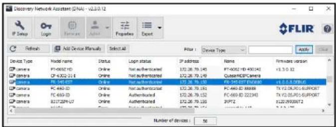
In the DNA Discover List, verify that the camera's status is Online.
If this is the first time you are configuring the camera or if it is the first time after resetting the camera to its factory defaults, DNA automatically authenticates the camera with the default password for the camera's admin user (admin).
If the admin user password has been changed, you need to authenticate the camera.
In the DNA Discover List, right-click the camera and select Login. In the DNA - Login window, type the password for the admin user. If you do not know the admin user password, contact the person who configured the camera's users and passwords.


Click Login, wait for Ok status to appear, and then click Close.
In the DNA Discover List, verify that the camera's status is Authenticated.
- Change the camera's IP address.
Right-click the camera and select IP Setup.
In the DNA - IP Setup window, clear Use DHCP and specify the camera's IP address. You can also specify the Mask (default: 255.255.255.0) and Gateway. Then, click Update, wait for Ok status to appear, and then click Close.

To manually specify the camera's IP address using the camera's web page:
- Access the camera's web page.
- On the View Settings Home Page, click System Settings, and make sure the Network page appears.
- Click Static IP addressing and then manually specify the camera's Hostname, IP address, Netmask, and Gateway.
You can also specify the DNS Mode, Name Servers, MTU (maximum transmission unit), and Ethernet Speed. - Click Save. Applying any changes on the Network page requires rebooting the camera.
2.6 Mount and Connect the Camera
Be sure to have the required accessories and tools available.
If using the CB-WLBX-G4 Wall & Surface Mount Kit with junction box, install it according to the installation guide for that accessory. Install the power and network cables in the junction box so that they are accessible when mounting the camera. If using other mounting hardware, install the mounting hardware for the camera according to instructions.
To mount the camera directly on a wall or ceiling and connect it:
- Attach the mounting template sticker onto the wall or ceiling where you are mounting the camera.
- Drill six anchor holes according to the template.
- Hammer the six plastic anchors into the drilled holes.
- If the system cable is going to exit from the rear, drill a hole in the center of the mounting template for the cable.
The system cable can exit either from the side of the camera's mounting bracket or through the hole in the back of the mounting bracket.


Rear Cable Exit

natural_image
Technical line drawing of a FLIX device connected to a vertical support structure (no text or symbols)Side Cable Exit
- Attach an Ethernet cable from the network switch to the RJ45 connector for a 10/100 Mbps Ethernet and IEEE 802.3at PoE+ connection. Ethernet is required for streaming video and for configuring the camera.
- Connect the alarm connectors, if needed.
- If using an external DC or AC power supply, connect its wires to the system cable's two-pin power connector.
For more information about the camera's connections, see Hardware Description.
- Place the camera over the surface and securely fasten the tapping screws clockwise into the plastic anchors.
Make sure that the camera's orientation covers the required field of view.

natural_image
Technical line drawing of a mechanical assembly with a motor and base plate (no text or symbols)Secure the Camera to the Surface
Related Documentation
• CB-WLBX-G4 Junction Box Kit Installation Guide
2.7 Aim and Boresight the Camera

Tip
Aim the camera while you are or someone else is monitoring the camera's live video on the camera web page or in a video stream.
While supporting the camera's weight with your hand and using the T10 Torx wrench, loosen the three locking screws and adjust the camera's pan, tilt, and rotation:
- Retaining ring for pan adjustment (1): Rotate the camera. You can also rotate the lens base until satisfied with the field of view. Do not exceed the ± 360^ pan range limit.
- Bracket for tilt adjustment (2): Adjust the bracket. Do not exceed the 0°\~90° tilt range limit.
- Retaining ring for 360° rotation (3): Rotate the camera body. Do not exceed the ±360° rotation range limit.

Important
While aiming the camera, make sure to support the camera's weight with your hand.
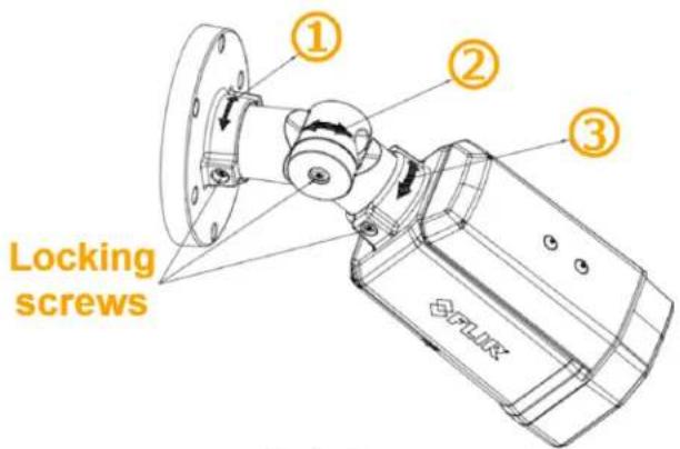
Aim the Camera
Make sure that the toothed surfaces are properly aligned and meet evenly.

Important
After aiming the camera, to prevent the camera from moving, use the T10 torx wrench to securely tighten each locking screw.

natural_image
Close-up of a white mechanical component with a red arrow and 'X' mark, no visible text or symbols
natural_image
Close-up of a white mechanical component with a green checkmark and arrow indicating a detail (no text or symbols present)Align the Surfaces
To boresight the camera:
- Use the default admin user or another user assigned either the admin or expert role to access and log into the camera's web page.
- On the View Settings Home Page, click System Settings, and then click Boresight to open the Boresight Page.
- Use the controls and settings on the Boresight page to align the visible video image with the thermal video image.
- Click Save.

Important
After powering up the camera, wait 30 minutes before commencing screening. The camera's thermal sensor needs to stabilize. In System Settings, click Boresight to open the Firmware & Info Page. Make sure the Temperature is stable.
2.8 Additional Configuration
Depending on how you are using the Elara FR-345-EST camera, along with the network and VMS to which it is connected, initial configuration using the camera's web page can also consist of:
| Configuration task | Camera's default admin user or any user assigned the admin or expert role | Any user |
| Create users, assign roles, and change passwords | User assigned the admin role | |
| Adjust the camera's date and time settings | • | |
| Enable or disable the camera's alarms | • | |
| Enable and configure external I/O devices | • | |
| Adjust the camera's live video and video stream settings | • | |
| Adjust the camera's visible video settings | • | |
| Adjust the camera's thermal video settings | • | |
| Adjust the camera's EST screening settings | • | |
| Enable and adjust the camera's OSD settings | • | |
| Enable and configure the camera's full-screen mode, which includes:• picture-in-picture• locking the camera web page in full-screen mode | • | |
Many of these configuration tasks can be performed before or after mounting the camera, but some of them can or should only be performed after mounting and connecting the camera.
2.9 Attach the Camera to a Supported VMS
After you have mounted the camera and discovered or defined its IP address, you can use VMS Discovery/Attach procedures to attach the camera to a supported VMS.
3 Operation
This chapter includes information about how to access the camera and how to operate it using the View Settings page.
3.1 Accessing the Camera
To operate the camera, you first need to access it. You can access the camera by logging in to the camera's web page. The camera's web page supports Google Chrome® and other popular web browsers.
To log in to the camera's web page:
1. Do one of the following:
In the FLIR Discovery Network Assistant (DNA) tool — version 2.3.0.19 or higher — double-click the camera in the Discover List.
The DNA tool does not require a license to use and version 2.3.0.19 or higher is a free download from the product's web page on FLIR.com. Download the DNA tool; unzip the file; and then
double-click to run the tool (DNA.exe). The Discover List appears, showing compatible devices on the VLAN.
- Type the camera's IP address in a browser's address bar (when the PC and the camera are on the same network). If you do not know the camera's IP address, you can use the DNA tool to discover it.
2. On the login screen, type a user name and the password.
When logging in to the camera for the first time or for the first time after resetting the camera to its factory defaults, type admin for the user name and for the password.
If you do not know the user name or password, contact the person who configured the camera's users and passwords.
- When logging in to the camera for the first time or for the first time after resetting the camera to its factory defaults, specify a new password for the admin user and then log back in using the new password.
Use a strong password consisting of at least 12 characters and at least one uppercase letter, one lowercase letter, and one number.
Passwords can include the following special characters: |@#\~!\$&<>+_-.,*?= .

The camera's View Settings home page appears.
3.2 View Settings Home Page
The View Settings page displays live video images of the selected view. When a user assigned the expert or admin role logs in to the camera's web page, the page also displays View Settings menus along the left side banner and other options.

View Settings page for users assigned the admin or expert role
System Settings
Users assigned the admin or expert role can click System Settings to configure the camera. For more information, see Configuration.
Live Video
You can select to view visible (V) or thermal (T) live video images.
The camera supports two visible video streams (V1 and V2). When V is selected for live video on the camera web page, images from the V1 stream appear. By default, the EST screening overlay is enabled and appears in the live video when V is selected. You can change this setting on the Screening Page. Also, when the camera's on-screen display (OSD) is enabled for the V1 stream on the OSD Page, the OSD appears in the live video image.
You can also set the Live Video Refresh Rate between 1-30 image frames per second (FPS).
The view selected and the Live Video Refresh Rate setting only affect the live video; they do not affect the camera's video streams.
Full Screen
The Elara FR-345-EST camera web page supports full-screen mode in browsers. Clicking enables full-screen mode. Enabling your browser's full-screen mode does not enable or disable the camera web page's full-screen mode.
Other Options
Additional choices are for Help and Logout.
3.3 Video Page
The camera provides three video streams: two visible streams (V1 and V2) and one thermal stream (T1). Video streams are available for viewing using a client program or third-party ONVIF systems.
In general, it is not necessary to modify the default parameters. In some cases, such as when an IP video stream is sent over a wireless network, it can be useful to tune the video streams to reduce the bandwidth requirements. To modify the parameters for a particular video stream, click the relevant button (V1, V2, or T1).
To apply any change to settings on the Video page, click Save. To restore previously saved settings or the factory default settings, click Reset.

Tip
On the camera web page, the live video is not the actual video stream. Changes to stream settings might not affect the live video. Check any changes to stream settings using a client program or third-party ONVIF system.
Visible 1 / Visible 2
Codec options for the visible streams are H.264 or MJPEG.
Resolution options are 1920x1080 (1080p); 1280x720 (720p); and 640x480 (480p). The Frame Rate range is 5-30 FPS (frames per second).
Thermal 1
Codec options are H.264 or MJPEG.
The resolution is 640x480 and the Frame Rate range is 5-25 FPS.

Codecs, Quality, and Bandwidth
The codec used determines which parameters you can set that have a significant impact on the quality and bandwidth requirements of the video stream. Use the default values initially, and then individual parameters can be modified and tested incrementally to determine when bandwidth and quality requirements are met.
With the H.264 codec, you can set the:
- Rate Control:
○ CBR (constant bit rate): The Bit Rate parameter defines the target bit rate; the camera attempts to keep the video at or near the target bit rate.
o VBR (variable bit rate): The Bit Rate parameter defines the average bit rate.
- I-frame Interval: Controls the number of P-frames used between I-frames. I-frames are full frames of video and the P-frames contain the changes that occurred since the last I-frame. A smaller I-Frame Interval results in higher bandwidth (more full frames sent) and better video quality. A higher I-frame Interval means fewer I-frames are sent and therefore can result in lower bandwidth and possibly lower quality.
With the MJPEG codec, you can set the Quality between 10-80. Setting a higher value can increase the video stream's bandwidth requirements.
Enable Multicast
By default, multicast is enabled. Multicast video packets are shared by streaming clients. Additional clients do not cause bandwidth to increase as dramatically as with unicast. Video stream requests for ch0/stream1 are unicast. Client-specific multicast requests vary according to the client.

Visible 1

Visible 2

Thermal 1
If more than one camera is providing multicast streams on the network, make sure the Destination Network IP address is unique for each camera (the Destination Port can be reused). By default, the port assignment is unique per stream.
The time-to-live field controls the ability of IP packets to traverse network boundaries. A value of 1 restricts the stream to the same subnet. Greater values allow increasing access between networks.
The video streaming uses a protocol generally referred to as RTP, the real-time transport protocol, although there are actually a number of protocols involved, including the Real-Time Streaming Protocol (RTSP). The video stream URLs incorporate the IP address of the camera. Using the camera's default IP address, the complete URLs are:
• Visible 1—rtsp://192.168.0.250:554/stream1
• Visible 2—rtsp://192.168.0.250:554/stream2
• Thermal 1—rtsp://192.168.0.250:554/stream3
To maintain compatibility with legacy systems, the stream names are aliased as: ch0 = stream1, ch1 = stream2, and ch2 = stream3.
Accessing any of the camera's video streams requires authentication. You can use the name and password for any of the camera's users. See Users Page.
3.4 Visible Page

You can adjust the following visible video settings:
- Brightness (Gamma)
- Contrast (Max Gain)
- Hue
- Saturation
- Sharpness
The camera immediately applies changes to settings on the Visible page, affecting the live visible video images and streams. To save those changes, click Save. To discard changes and restore previously saved settings or the factory default settings, click Reset.
If you make changes to the settings, do not save the changes, and try to navigate to a different page, a confirmation message appears. You can discard the changes you made, save the changes, or continue without saving the changes. For example, if you would like to test settings before saving them.
Advanced Settings
• Night Mode—Set the visible video to:
○ Color (day mode)
○ B/W (night mode)
○ Auto (default)—Automatically switches the visible video mode according to light level. When Night Mode is set to Auto, you can set the thresholds at which the visible video switches from black and white to color (Night to Day Threshold) and vice versa (Day to Night Threshold). Move the sliders between 0-100, where 0 switches modes at a lower light level (darker) and 100 switches modes at a higher light level (brighter).

![Advanced Settings ^ Night Mode Color B/W Auto Night to Day Threshold [0-100] 50 Day to Night Threshold [0-100] 50 Wide Dynamic Range On Off](/content/2026/05/1094158/images/3dd1b978dcbd06e3066b75960ce2c5a10f451cdc2830f01c3246776a05e7e6ab.jpg)
- Wide Dynamic Range
WDR improves the image quality and amount of detail in high contrast scenes. High contrast scenes consist of areas with different lighting conditions; some areas are bright and others are dark. Without WDR, either the bright areas would be overexposed (too bright) or the darker areas would be completely dark. WDR can produce more detail in both the dark and the bright areas of the image.
- White Balance—Set according to operating environment:
○ Auto (default)—Computes the white balance value output using color information from the entire screen. It is suitable for an environment with a light source color temperature in the range of approximately 2,700 \~ 7,500K.
○ One Push—Click One Push Trigger to activate the factory-optimized setting for white balance. This setting might not be ideal for every lighting environment.
○ ATW (Auto Tracking White Balance)—Automatically adjusts the white balance in a scene while temperature color is changing. It is suitable for an environment with a light source color temperature in the range of approximately 2500 \~ 10,000K.
o Manual—Define the Rgain and Bgain between 0-100 to increase the red and blue luminance.
![White Balance ATW One Push Trigger Color Noise Reduction Off 20 Noise Reduction [0-100] 0 30 Noise Reduction [0-100] 20](/content/2026/05/1094158/images/9d36c1122c1951b21ab2c6f6c96dad60cd3579e3d251fd94ef173fb7d9cbb589.jpg)
- Noise reduction settings
Noise reduction settings are used to reduce or eliminate artifacts that can limit the ability to positively identify an object. There are two types of noise: luminance and color (chroma) noise. 3D noise reduction and 2D noise reduction settings reduce luminance noise: dots of varying brightness levels (black, white, and gray). It is not recommended to completely eliminate luminance noise, which can result in unnatural images. The 3D Noise Reduction and 2D Noise Reduction settings should be configured after configuring Color Noise Reduction.
○ Color Noise Reduction—Controls the noise appearing as red, green and blue dots between light and dark areas. Four settings are available: Off, Low, Mid, High. High maximizes the blending of the color noise with the image, effectively removing the dots, while Low minimizes the blending.
- 2D Noise Reduction—Analyzes individual frames pixel by pixel and frame by frame to eliminate environmental noise and deliver optimized image quality, especially in low-light conditions. 2D noise reduction tends to produce superior results for moving objects when applied to areas in the field of view where movement is present. However, it is less precise than 3D noise reduction. It can be set On or Off.
- 3D Noise Reduction—Provides superior noise reduction and is recommended for use in extra low-light conditions. It is especially useful for reducing blur with moving objects. 3D noise reduction reduces image noise/snow in low-light conditions by comparing adjacent frames. A higher level of 3D noise reduction generates relatively enhanced noise reduction, although it creates more motion blur than 2D noise reduction on moving objects. Four settings are available: Off, Low, Mid, High.
- Backlight Compensation (BLC)—Detects images with a bright light source behind the subject of interest and adjusts the exposure of the entire image to properly expose the subject in the foreground. Without backlight compensation, the subject appears in silhouette.

The settings available are: Off (default), Upper, Lower, Center 1/3, Center 1/6, Left, or Right:

Upper

Lower

Center 1/3

Center 1/6

Left

Right

OFF
Backlight Compensation Settings
- Exposure Mode
Exposure is the amount of light detected by the image sensor and is determined by the amount of time the shutter is open (shutter speed), and other exposure parameters.
○ Auto Shutter—Select a minimum and a maximum shutter speed. Generally used where light levels are fixed and the Flickerless mode does not provide the optimal exposure. This mode is recommended for scenes where there is a fixed lighting contrast and a constant, precise exposure is required.
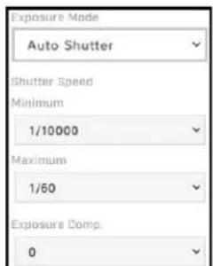
Auto Shutter Exposure Mode Settings
- Minimum Shutter Speed—Select the slowest shutter speed based on the amount of light in the scene. A slower shutter speed increases the amount of light entering the sensor and results in a brighter, more-detailed image. The Video Format determines the minimum shutter speeds available, listed in the following table from slowest to fastest, in fractions of a second:
| Minimum Shutter Speed - Auto Shutter Mode | |||||
| NTSC | PAL | ||||
| 1 | 1/250 | 1/8000 | 1 | 1/250 | 1/8000 |
| 1/2 | 1/400 | 1/10000 | 1/2 | 1/400 | 1/10000 |
| 1/4 | 1/500 | 1/12500 | 1/4 | 1/500 | 1/12500 |
| 1/7.5 | 1/800 | 1/16000 | 1/6.25 | 1/800 | 1/16000 |
| 1/15 | 1/1000 | 1/20000 | 1/12.5 | 1/1000 | 1/20000 |
| 1/30 | 1/2000 | 1/25000 | 1/25 | 1/2000 | 1/25000 |
| 1/60 | 1/2500 | 1/32000 | 1/50 | 1/2500 | 1/32000 |
| 1/120 | 1/4000 | 1/100 | 1/4000 | ||
| 1/200 | 1/5000 | 1/200 | 1/5000 | ||
- Maximum Shutter Speed—Select the fastest shutter speed based on the amount of light in the scene. A faster shutter speed decreases the amount of light entering the sensor and results in a darker image. The Video Format determines the maximum shutter speeds available, listed in the following table from slowest to fastest, in fractions of a second:
| Maximum Shutter Speed - Auto Shutter Mode | |||||
| NTSC | PAL | ||||
| 1/120 | 1/1000 | 1/10000 | 1/100 | 1/1000 | 1/10000 |
| 1/200 | 1/2000 | 1/12500 | 1/200 | 1/2000 | 1/12500 |
| 1/250 | 1/2500 | 1/16000 | 1/250 | 1/2500 | 1/16000 |
| 1/400 | 1/4000 | 1/20000 | 1/400 | 1/4000 | 1/20000 |
| 1/500 | 1/5000 | 1/25000 | 1/500 | 1/5000 | 1/25000 |
| 1/800 | 1/8000 | 1/32000 | 1/800 | 1/8000 | 1/32000 |
- Shutter Priority—Specify a fixed shutter speed.
- Flickerless (default)—Eliminates flicker caused by fluorescent lighting in the screening area. Specify the mode.
- Mode—Specify the power used for lighting the scene, 50Hz or 60Hz.
- Manual—Specify a fixed shutter speed and the gain.
- Gain—A higher value increases the sensitivity of the image sensor, which brightens the image and adds details, but also increases the noise level. Define a value between 0-100.
| Shutter Speed - Shutter Priority and Manual Exposure Modes | |||||
| NTSC | PAL | ||||
| 1/7.5 | 1/500 | 1/10000 | 1 | 1/250 | 1/8000 |
| 1/15 | 1/800 | 1/12500 | 1/2 | 1/400 | 1/10000 |
| 1/30 | 1/1000 | 1/16000 | 1/4 | 1/500 | 1/12500 |
| 1/60 | 1/2000 | 1/20000 | 1/6.25 | 1/800 | 1/16000 |
| 1/120 | 1/2500 | 1/25000 | 1/12.5 | 1/1000 | 1/20000 |
| 1/200 | 1/4000 | 1/32000 | 1/25 | 1/2000 | 1/25000 |
| 1/250 | 1/5000 | 1/50 | 1/2500 | 1/32000 | |
| 1/400 | 1/8000 | 1/100 | 1/4000 | ||
| 1/200 | 1/5000 | ||||
- Exposure Comp. (compensation)—Adjusts the exposure for the entire image. The exposure compensation setting is not available in Manual exposure mode.
3.5 Thermal Page
In most installations, it is not necessary to change the default settings of the thermal sensor. However, in some situations, depending on scene, modifying one or more parameters can improve the image. Be aware that, when the conditions change, the parameters might need to be adjusted again. It is also a good idea to know how to restore the factory default settings (see Firmware & Info Page).
The camera immediately applies changes to settings on the Thermal page, affecting the live thermal video images and streams. To save those changes, click Save. To discard changes and restore previously saved settings or the factory default settings, click Reset. If you make changes to the settings, do not save the changes, and try to navigate to a different page, a confirmation message appears. You can discard the changes you made, save the changes, or continue without saving the changes. For example, if you would like to test settings before saving them.
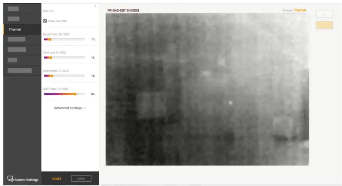
AGC ROI
The camera's Automatic Gain Control (AGC) algorithm adjusts the thermal video according to the region of interest (ROI). By default, the ROI is Full screen; the camera's AGC algorithm considers the entire image. In some cases, defining an ROI that excludes a portion of the screen can improve the image. For example, if there is an air conditioning vent in the image. Defining the ROI to exclude the vent might improve contrast in the rest of the image.

Caution
The camera's video analytics rely on accurate and useful AGC settings. Radical changes to the ROI can affect the camera's video analytics features; for example, canthus detection.
In addition to Full screen, you can select from a number of preset options or manually define the ROI by selecting Custom.
By default, Show AGC ROI is selected and the AGC ROI appears as an overlay in the live video on the camera web page. The AGC ROI overlay does not appear in the video stream itself.
Defining a custom AGC ROI
To change the size of the ROI: Hover over the handle in the bottom-right corner of the ROI, and then click and drag it.
To move the entire ROI: Hover over the ROI, and then click and drag it.

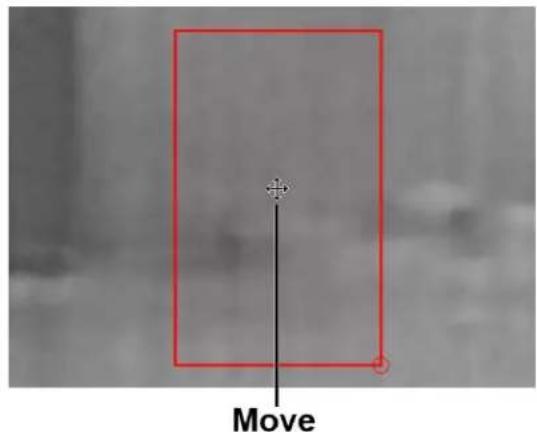
As soon as you manually change the size of the ROI or move it, the AGC ROI setting automatically changes to Custom.
AGC Image Settings
In some cases, changing the AGC image settings can provide a better image, depending on personal preferences, display devices, and so on.
- Brightness (Gamma)—Determines the allocation of the 256 “shades of gray” produced by the AGC. Values above 50 allocate more shades of gray to hotter objects, while values below 50 allocate more shades of gray to lower temperature objects. Range 0 to 100.
- Contrast (Max Gain)—Increasing contrast can provide a better image, especially for scenes with little temperature variation. (It might also increase noise due to the increased gain.) Range 0 to 100.

Tip
Changes to the default contrast setting affect scenes with little temperature variation more than they affect scenes with greater temperature variation.
- Sharpness (DDE Gain)—Enhances image details and/or suppresses fixed pattern noise. Range 0 to 100.
- AGC Filter—Determines how quickly a scene adjusts when a hot object appears (or disappears) within the AGC ROI. If set to a low value, when a hot object enters the ROI, the AGC will adjust more slowly to the hot object, resulting in a more gradual transition. Range 0 to 100.
Advanced Settings
- Tail Rejection—Defines the percentage of the total number of pixels in the array the camera excludes prior to maximizing the dynamic range available for the content of the scene. Specify the specified percentage of pixels the cameras removes from both the highest and lowest end of the scene's dynamic range prior to AGC. This excludes outliers and the most extreme portions of the scene that might be of less interest. To avoid excluding important scene content, FLIR recommends specifying tail rejection less than 1%. Range 0 to 100.
- Plateau Value—Defines how many shades of gray the camera devotes to large areas of similar temperature in the scene. Increasing the plateau value increases the shades of gray the camera devotes to those large areas, and vice versa. Range 0 to 100.
- Linear Percent—Defines the percentage of linearity the camera incorporates into the data mapping. Increasing the linear percent value more accurately retains the visual representation of an object's temperature. Range 0 to 100.
- Detail Headroom—Defines the amount of 8-bit dynamic range the histogram-equalized data uses. Increasing the detail headroom value increases the shades of gray the camera devotes to the top and bottom of the dynamic range. Range 0 to 100.
- Smoothing Factor—Defines how much of the scene DDE enhances or suppresses. Range 0 to 100.
3.6 Input/Output (I/O) Page
Adjust local and external I/O settings on the I/O page.
- For local I/O connections:

For information about the local I/O connector, see I/O Devices Page.
![Output settings Local External Input Output State Show whether the input pin is On or Off On off Current state Idle State Choose the desired state in which the pin is not alarmed Open Closed Reset interval [0-120 sec] Choose 0 to disable the auto reset for the output pin 0 Set reset interval RESET SAVE Save](/content/2026/05/1094158/images/102f468580bcbd44983096dd30366d91113212fb135a54ed6740c10970ac6c74.jpg)

bar
Advanced Settings | Setting | Value | |---|---| | Tall Rejection [0-100] | 0 | | Plateau Value [0-100] | 6 | | Linear Percent [0-100] | 20 | | Detail Headroom [0-100] | 9 | | Smoothing Factor [0-100] | 61 |- For external I/O connections, set the current state for the input and output pins, as shown at right.
You can configure the external I/O connections, including the number of external input and output pins, on the I/O Devices Page in System Settings.

The camera immediately applies changes to settings on the I/O page. To save those changes, click Save. To discard changes and restore previously saved settings or the factory default settings, click Reset. If you make changes to the settings, do not save the changes, and try to navigate to a different page, a confirmation message appears. You can discard the changes you made, save the changes, or continue without saving the changes. For example, if you would like to test settings before saving them.
3.7 Screening Page
The camera's screening function detects elevated skin temperatures by measuring the temperature of the skin around the tear duct (the canthus). You can enable, disable, or adjust the following screening settings:
- Screening Enable—Enables the camera's temperature screening. The default setting is On (enabled).
- Overlay Enable—Enables the screening overlay in the live video on the camera's web page. The default setting is On (enabled).
- Display Temperature—Enables the detected temperature in the live video on the camera's web page. The default setting is On (enabled).
- Face Covering Detection—Enables the camera's face covering detection feature. Select one of the following:
○ Off (default)
o No Face Covering Alert—When the camera detects a person being screened is not wearing a face covering and is not attempting to fool the camera by covering his or her face with another object, it generates an on-screen alert, but does not take any other action.
- No Face Covering No Entry—Effective when the camera is installed with an entry control system and is properly configured on the System Settings Alarm and I/O Devices pages. When the camera detects a person being screened is not wearing a face covering and is not attempting to fool the camera by covering his or her face with another object, it generates an on-screen alert and triggers an alarm output signal that the access control system uses to prevent entry.
The camera immediately applies changes to settings on the Screening page, affecting the live video images and streams. To save those changes, click Save. To discard changes and restore previously saved settings or the factory default settings, click Reset. If you make changes to the settings, do not save the changes, and try to navigate to a different page, a confirmation message appears. You can
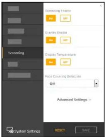
discard the changes you made, save the changes, or continue without saving the changes. For example, if you would like to test settings before saving them.
Advanced Settings
- Temperature Units—Select Celsius (default) or Fahrenheit.
- Temperature Offset—Select On or Off (default).
When you enable temperature offset, you can specify the number of degrees the camera uses to calculate the alarm threshold, in positive whole numbers. The alarm threshold is the sum of the reference temperature average and the configured offset. A smaller offset detects smaller elevations in skin temperatures, but also generates more false positives. A larger offset leads to fewer false positives, but also misses more people with elevated skin temperatures; for example, those whose normal skin temperature is colder than the average or coming from a colder environment. By default, when enabled, the temperature offset is 1.0^ C ( 1.8^ F).

The camera only stores the temperature values of some measurements used for the calculation of the reference temperature average. It is impossible to connect these values to any individual.
- Full Overlay On Stream—Enables the full overlay, including the temperature, in the camera's video streams. The default setting is Off (disabled).
Layout Configuration
You can configure the following screening layout settings:
- Text Color
- Font Style
- Status messages
For each of the following screening statuses, you can configure Title and Instructions messages, along with the indicating color, that appear in the screening overlay when it is enabled:
- No elevated temperature detected
- Elevated temperature
○ Low temperature - Face without face covering not detected
○ Measurement pending

Tip
Make sure people being screened can clearly read the messages. The legibility of the messages on the camera web page and in the video streams depends on a number of factors, including screening station screen size and resolution, video stream resolution, font style, and message length.
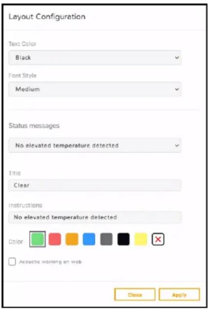
- Acoustic warning on web—The camera generates audio signals through its web page when:
- The measured skin temperature of the person being screened is higher than the Temperature Offset specified.
The camera detects a person being screened is not wearing a face covering and is not attempting to fool the camera by covering his or her face with another object. - The measured skin temperature of the person being screened is within the Temperature Offset specified.
To immediately apply changes to the layout configuration, click Apply.
Screening Enabled Examples
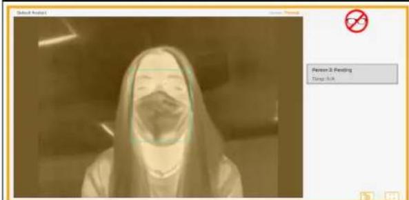
Pending Measurement - Screening Overlay On Landscape Orientation - Full-Screen Mode - Locked Thermal Video

Normal Temperature Measured Display Temperature On

Low Temperature Measured

Eyeglasses Prevent Measurement
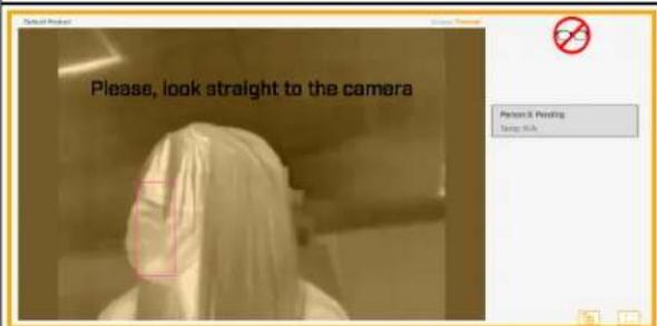
Not Looking at Camera Prevents Measurement

Distance from Camera Prevents Measurement
Screening Enabled Examples


Normal Temperature Measured Display Temperature On

Eyeglasses Prevent Measurement Full-Screen Mode Visible Video
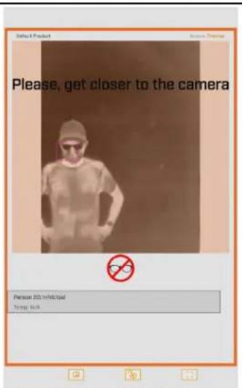
Distance from Camera Prevents Measurement

Elevated Temperature Measured
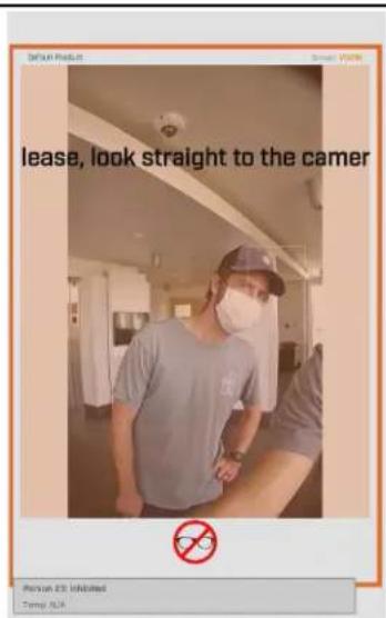
Not Looking at Camera Prevents Measurement
For information about full-screen mode, see Full-Screen Mode.
3.8 OSD Page
The camera can provide an on-screen display of the camera's name as defined on the Firmware & Info page, and the date and time. For each stream (V1, V2, and T1), you can:
- Enable or disable the OSD
- Enable or disable the camera name
- Enable or disable the date & time
You can also specify:
- Text Color—Black or white, with or without a background
- Font Size—Small, medium, big, or giant
- Position Camera Name—Top or bottom; left, center, or right
- Position Date & Time—Top or bottom; left, center, or right
- Bold
When enabled, the OSD appears in the video streams.
When V is selected for the live video view on the camera web page, the V1 stream appears. Therefore, when OSD is enabled for the V1 stream, the OSD appears in the live video image. Enabling OSD on the V2 stream does not affect the live video on the camera web page.

The camera immediately applies changes to settings on the OSD page, affecting the live video images and streams. To save
those changes, click Save. To discard changes and restore previously saved settings or the factory default settings, click Reset. If you make changes to the settings, do not save the changes, and try to navigate to a different page, a confirmation message appears. You can discard the changes you made, save the changes, or continue without saving the changes. For example, if you would like to test settings before saving them.
3.9 Georeference Page
Use the Georeference page to specify the camera's geographical location and mounting position.
For geographical location, specify:
• Latitude, in degrees North or South
• Longitude, in degrees East or West

Tip
To obtain the camera's latitude and longitude, use a map or a mobile GPS device.

For mounting position, specify:
• Ground Altitude, in meters above or below sea level
• Installation Height, in meters above the ground (must be greater than zero)
- Orientation: the installation angle of the camera, between 0-360 degrees from North
To apply any change to settings on the Georeference page, click Save. To restore previously saved settings or the factory default settings, click Reset.
3.10 Full-Screen Mode
When the Elara FR-345-EST camera's web page will be shown to people being screened, you do not want them to be able to access View Settings menus and System Settings. Therefore, you can enable the camera web page's full-screen mode by clicking [ ] on the View Settings Home Page.
In full-screen mode, you can:
- Enable picture-in-picture—If thermal video appears in the primary view, visible video appears in a smaller, floating picture, and vice versa.
- Lock the camera web page in full-screen mode—To prevent people being screened from disabling full-screen mode and accessing View Settings menus and System Settings. When the camera web page is in full-screen mode, View Settings menus and System Settings are not available.
- Exit full-screen mode

Tips
- Before enabling full-screen mode, set up, configure, and verify the camera's web page settings. Specifically, on the View Settings Home Page, select the primary view for the display device, thermal or visible video.
- To view full-screen mode in portrait orientation, rotate the display device 90°; for example, if you are using a tablet computer as the display device. Make sure auto-rotation is enabled on the display device. This topic and the example images in it reflect the camera's web page in full-screen mode and in landscape orientation, except where noted. The camera's web page in full-screen mode and in portrait orientation is similar.
- When the camera web page is not in full-screen mode, FLIR recommends viewing it in landscape orientation.
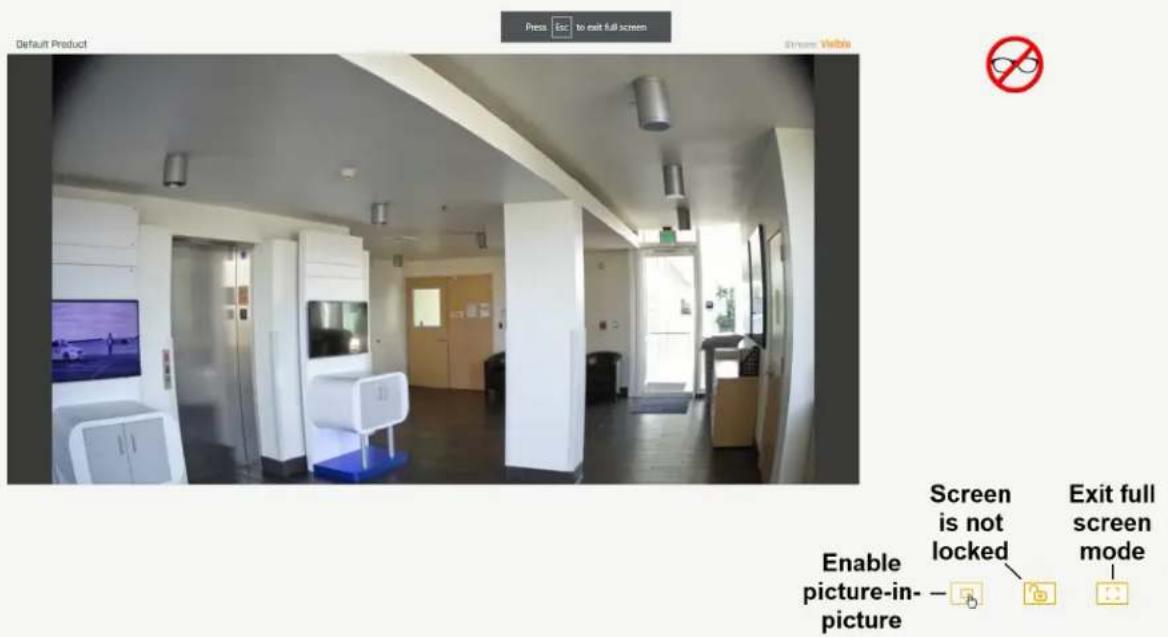
Full Screen Mode - Landscape Orientation
Picture-in-Picture
Click


You can move the picture-in-picture around the screen; click the top bar of the picture-in-picture and drag it.

Tip
Before locking the camera web page in full-screen mode, position the picture-in-picture.
You can close the picture-in-picture by clicking the close window icon, including when the camera web page is locked in full-screen mode.
Lock the Camera Web Page in Full-Screen Mode
Click

Then, enter a password and click Lock.
Use a strong password consisting of at least 12 characters and at least one uppercase letter, one lowercase letter, and one number. Passwords can include the following special characters: |@#\~!\$&<>+_-,*?=
When the camera web page is locked in full-screen mode:
- It is still possible to enable picture-in-picture.
• The camera web page session does not expire.
When the camera web page is not locked in full-screen mode, after 15 minutes of inactivity, the camera web page session expires.
However, clicking ☐ does not exit full-screen mode. To unlock the camera web page, click 🔒. Enter the password you used to lock the camera web page in full-screen mode. Then, you can exit full-screen mode by clicking ☐.

4 Configuration
Users assigned the admin or expert role can click System Settings on the View Settings Home Page to configure:
- Networking
• I/O devices
- Date and time
- Cybersecurity
• User accounts and passwords
- Boresight Page
- Alarm settings
In addition, users assigned the admin or expert role can access the Firmware & Info page to upgrade the camera's firmware, reset the camera to its factory defaults, reboot the camera, and configure other parameters.
4.1 Network Page
When a user assigned the expert or admin role clicks System Settings, the Network page appears.

To apply any change to settings on the Network page, click Save. Applying these changes requires rebooting the camera. To restore previously saved settings, click Discard Changes.
The IP address mode can be set to DHCP (default) or Static.
The Hostname Mode can be set to DHCP or Static (default). Define the camera's hostname, which identifies the camera. For example, in the camera's overlay.
When the IP address mode is Static, specify:
• IP—The camera's IP address
• Netmask—The default value is 255.255.255.0
- Gateway
When the IP address mode is set to DHCP, if a DHCP server is not available on the network, the camera's default IP address is 192.168.0.250. For information about defining the camera's IP address using the DNA tool, see Initial Configuration.

Caution
After changing the camera's IP address, the PC you are using to access the camera's web page might no longer be on the same network as the camera and can no longer access the camera's web page. To access the camera web page again, change the PC's IP address to be on the same network as the camera.
When the IP address mode is DHCP, you can set the DNS Mode to DHCP or Static. When the IP address mode is Static, the DNS Mode is also Static.
When the DNS Mode is set to Static, specify:
- Name Server 1—The primary domain name server that translates host names into IP addresses
- Name Server 2—A secondary domain name server that backs up the primary DNS
You can also specify the:
- MTU—Maximum transmission unit, the largest amount of data that can be transferred in one physical frame on the network. For Ethernet, the MTU is 1500 bytes (the default setting). For PPPoE, the MTU is 1492. Valid values are 1000-1500.
- Ethernet Speed—When set to 100Mbps (default), the camera supports 100Mbps. When set to Auto, the camera supports 10/100 Mbps.
4.2 Date & Time Page

The camera can obtain the date, time, and time zone from an NTP server, or click Manual and either copy the local PC's time or specify the hour, minute, second, and date.

When the camera's date and time is set to NTP, you can specify whether the camera obtains the NTP server information from the DHCP server on the network, or click Manual and specify the NTP server address. To specify more than one NTP server, use a comma to separate the addresses.
To apply any change to settings on the Date & Time page, click Save. Applying these changes requires rebooting the camera. To restore previously saved settings, click Discard Changes.
4.3 Users Page
Only users assigned the admin role can add users and change or set all passwords.

Users assigned the expert role only see the user currently logged in, and cannot add, edit, or delete a user.
To maintain security of the system, set up user names and passwords for each required login account.
Passwords must consist of at least 12 characters and include at least one uppercase letter, one lowercase letter, and one number. Passwords can include the following special characters: |@#\~!\$&<>+_-.,*?= .
Assign one of the following roles, according to the level of access the user requires:
| Role | Access |
| user | Can:View live videoSwitch between visible and thermal live videoView the Help pageLog out |
| expert | Cannot manage users:Cannot add/edit/delete usersCannot change passwordsCan access and use all other View Settings and System Settings pages, menus, controls, and settings |
| admin | Can access and use all of the camera's web pages, including adding / editing / deleting users (but cannot delete the default admin user), and setting all passwords |
All roles can access the camera's video streams, which require authentication. You can use the name and password for any of the camera's users.


To keep the existing password, leave the password fields empty.
Delete User

4.4 Alarm Page

You can enable or disable the following alarms:
- Output On Normal Temp—When the measured skin temperature of the person being screened is within the offset specified on the Screening Page, the camera generates an output signal at the local I/O connector.
- Output On Elevated Temp—When the measured skin temperature of the person being screened is higher than the offset specified on the Screening Page, the camera generates an output signal at the local I/O connector.
- Output On No Face Covering—When the camera detects a person being screened is not wearing a face covering and is not attempting to fool the camera by covering his or her face with another object, the camera generates an output signal at the local I/O connector.
- Output On Any Alarm—The camera generates an output signal at the local I/O connector when it detects either elevated temperature or no face covering.
- Arm/Disarm Analytics with Input—An input signal at the local I/O connector toggles the camera's video analytics detection status. By default, it is disabled.
To apply any change to settings on the Alarm page, click Save. To restore previously saved settings, click Discard Changes.
4.5 I/O Devices Page
The I/O Devices page provides configuration settings for external I/O connections and the device managing those connections with the camera.

The following settings for the device managing the external I/O connections are available:
- Enabled or Disabled
• Device IP address and port - Input and output base addresses
You can define the number of input and output pins the device manages.
The following information appears for each pin:
- I/O pin number
- Type—Input or Output
• State—the pin's current state: Open or Closed
For each pin, you can define the following:
- Idle State—Open or Closed
• Alarm Auto Ack—Yes or No - Enabled—Yes or No
- Reset Interval (for output pins only)—between 0-600 seconds; specifying 0 seconds disables the auto reset
To apply any change to settings on the I/O Devices page, click Save. To restore previously saved settings, click Discard Changes.
For more information about how to configure the device managing the external I/O connections, refer to the device's documentation.
4.6 Cyber Page
The Cyber page provides security configuration settings for:
- Certificates
• IEEE 802.1X-compliant communication
• Transport Layer Security (TLS) and secure HTTP (HTTPS) communication
• Other cybersecurity services
To apply any change to the security configuration settings on the Cyber page, click Save. Applying these changes requires rebooting the camera. To restore previously saved settings, click Discard Changes.

4.6.1 Certificates
Before you can enable TLS/HTTPS or 802.1X, you need to generate or upload a valid certificate. You can:
- Use the camera's web page to generate a self-signed certificate.
- Upload a self-signed certificate.
- Upload a certificate signed by a third-party.
Certificates and keys must be in PEM format. Common file extensions for TLS files in PEM format are:
- For certificate and public key files: *.crt, *.cer, *.cert, *.pem
- For private key files: *.key
From the Certificates section of the Cyber page, you can download certificates and keys previously uploaded to or generated by the camera. If the certificate saved on the camera is self-signed, you can download the private and public key files. If the certificate was signed by a third-party CA, you can download the CA Certificate and the private and public key files.
To generate and install a self-signed certificate for TLS/HTTPS:
-
In the Certificates section and Certification area, select TLS/HTTPS and Self-Signed.
-
Enter information such as country code, city name, and organization name.
-
Click Create Certificate.
-
Allow 15 seconds for the camera to generate the certificate, at which point a confirmation appears.

To upload a self-signed or third-party CA signed certificate for TLS/HTTPS or for 802.1X:
- In the Certification area, click TLS/HTTPS and then select Upload Certificates, or click 802.1x.
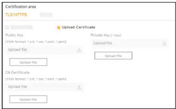
To upload a certificate for TLS/HTTPS
![Certification area 802.1x Public Key [PEM format: *crt, *car, *crt, *gem] Upload file Upload file CA Certificate [PEM format: *crt, *car, *crt, *gem] Upload file Upload file Private Key (*.kns) Upload file: Upload file](/content/2026/05/1094158/images/fa56f502dbce27d7f78433d37c1b67ba196c82e686d5b602572d955fa69c6574.jpg)
To upload a certificate for 802.1X
- If you are uploading a self-signed certificate, under Public Key and then under Private Key:
a. Click


b. Select the appropriate key file.
c. Click

If you are uploading a third-party CA signed certificate, select and upload the Public Key, Private Key, and CA Certificate.
- Verify that the camera certificate files are valid and make sure Certificates are OK appears under the certificate information, under Download certificate.

Note that you can download keys and certificates from the camera.
Changes in the Certificates section do not immediately take effect. To apply changes, click Save and then reboot the camera.
4.6.2 802.1x
Enable or disable IEEE 802.1X-compliant TLS communication.
Provide an Identity and Private Key Password.

4.6.3 TLS/HTTPS
Enable or disable camera control using Transport Layer Security (TLS)/secure HTTP (HTTPS).
Enable or disable HTTPS redirect.
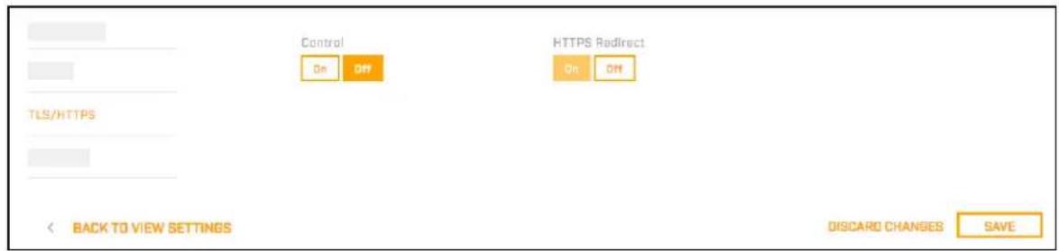
4.6.4 Services
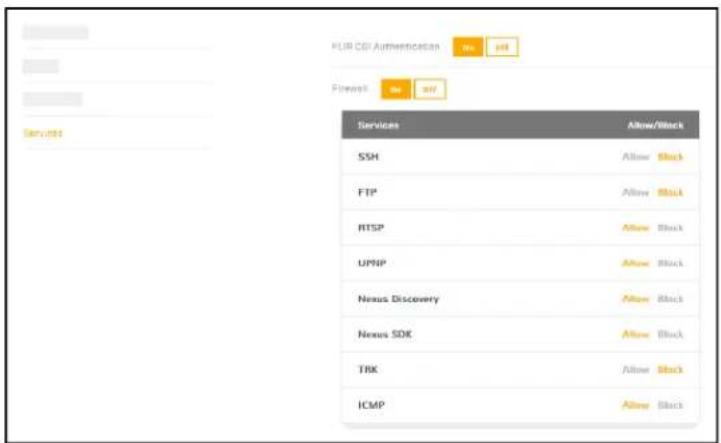
Enable or disable digest authentication for the FLIR CGI control interface. The default setting is On (enabled).
Firewall Settings
For enhanced security, the camera has a firewall that you can enable by clicking On. By default, when you enable the firewall, the following services are set to Allow, which means they remain enabled and their default ports remain open:
- SSH
- Nexus Discovery
- FTP
- Nexus SDK
- RTSP
- TRK
- UPNP
- ICMP
To disable a service and its default port, click Block.

Caution
Disabling services and ports can affect product functionality.
4.7 Boresight Page
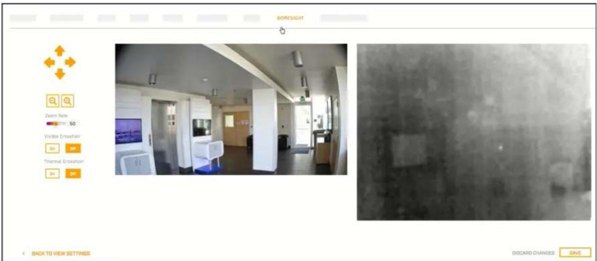
Use the controls and settings on the Boresight page to align the visible video image with the thermal video image.

Changing the settings on the Boresight page immediately affects the live video and video streams. To save these changes, click Save. To discard changes and restore previously saved settings, click Discard Changes.
Both cameras' focus is fixed at one meter (39.4") and the camera uses digital zoom to adapt the visible camera's field of view (FOV) to the thermal sensor's FOV.
4.8 Firmware & Info Page
On the Firmware & Info page, you can:
- Specify a unique name for the camera
- Upgrade the camera's firmware
- Reset the camera to its factory defaults
- Reboot the camera
- Change the camera's video format
- Enable logs, define a log level, and download system information
- Enable the compatibility mode for legacy VMS versions
- Define whether the camera is mounted upright or at a 90^ angle
To apply any change to settings on the Firmware & Info page, click Save. Applying these changes requires rebooting the camera. To restore previously saved settings, click Discard Changes.

Name
Specify a unique, friendly name for the camera, using only alphanumeric characters. The default name for the camera is the camera model followed by the camera's serial number.

To upgrade the camera's firmware:
-
Make sure the camera has been recently rebooted.
-
Under Upgrade version, click Find file.
-
On your computer or network, browse to and select the firmware file.
Caution
Only upgrade firmware developed for the Elara FR-345-EST camera.
4. Click Upgrade.
The camera uploads and installs the firmware, which takes a minute or two. After installing firmware, the camera requires a reboot. When prompted, confirm rebooting the camera.
Factory Defaults
Click Full Reset to return the camera its original factory configuration.
Click Partial Reset to keep the current settings on the Network page and return all other settings to their factory defaults.
Click Reboot to cause the camera to power cycle and reinstall configuration files.
Tip
You can also return the camera to its original factory configuration by pressing the camera's physical Default button for at least six seconds; for example, if you are unable to access the camera via its web page or other communication method. The Default button is located on the camera's connector panel.
Support System Info
Set the logging detail up to four levels; higher log levels increase the size of the log file.
Click Download to retrieve the camera's log files.
Other Settings
Installation Mode—If the camera is installed at a 90° angle, select Rotation 90. Otherwise, make sure Rotation 0 is selected.
Video Format—The visible camera shutter speed can be synchronized to the 50 Hz or 60 Hz power used for lighting the scene. If lighting is connected to 50 Hz power, the PAL setting might provide better video. Under 60 Hz lighting, NTSC might provide better video.
For legacy VMS versions, enable the compatibility mode.
5 Maintenance and Troubleshooting Tips
If help is needed during installation, operation, or configuration, contact the local FLIR representative, or visit the FLIR Support Center at: https://support.flir.com/. FLIR Systems, Inc. offers a comprehensive selection of training courses to help get the best performance and value from the thermal imaging camera.
Find out more at the FLIR training web page: https://www.flir.com/support-center/training/.
5.1 Cleaning
Great care should be used with your camera. It is delicate and can be damaged by improper cleaning.

Note
Do not disturb or move camera during cleaning. The face covering detection and other features on the camera are set and calibrated based on the exact position and camera angle. Inadvertent realignment might require relocation and recalibration.
You can keep the camera clean by using a clean soft cotton cloth lightly dampened with fresh water to carefully wipe the camera housing and the front of the camera.

Caution
Make sure no liquid, dust, dirt, or other material enters the camera sensor openings. The camera's optics are delicate and can be damaged by improper cleaning.
Do not use abrasive materials, such as paper or scrub brushes, as this can damage the camera housing by scratching it.
5.2 Troubleshooting
No Video
If the camera will not produce an image, check the connections at the camera and at the display. If the connectors appear to be properly connected but the camera still does not produce an image, ensure that power has been properly applied to the camera and the circuit breaker is set properly. If a fuse was used, be sure the fuse is not blown.
If the camera still does not produce an image, contact the FLIR dealer or reseller who provided the camera, or contact FLIR directly.
Thermal Image Freezes Momentarily
By design, the camera image momentarily freezes during Flat-Field Correction (FFC, and also known as Non-Uniformity Correction or NUC). At regular intervals or when the ambient temperature changes, the camera automatically performs FFC. You can also manually trigger FFC on the Thermal page. The shutter for the thermal sensor closes and provides a target of uniform temperature, allowing the thermal sensor to correct for ambient temperature changes and provide the best possible image.
Unable to Communicate over Ethernet
First check to ensure the physical connections are intact and that the camera is powered on.
By default, the camera broadcasts a discovery packet twice per second. Use version 2.3.0.19 or higher of the FLIR Discovery Network Assistant (DNA) tool or a packet sniffer utility such as Wireshark and confirm the packets are being received by the PC from the camera.
Unable to View Video Stream
If the video stream from the camera is not displayed, it could be that the packets are blocked by the firewall, or there could be a conflict with video codecs that are installed for other video programs.
When displaying video with a VMS for the first time, the Windows Personal Firewall may ask for permission to allow the video player to communicate on the network. Select the check boxes (domain/private/public) that are appropriate for the network.
If necessary, test to make sure the video from the camera can be viewed by a generic video player such as VLC media player (http://www.videolan.org/vlc/). To view the video stream, specify RTSP port 554 and the appropriate stream name. For example, using the camera's default IP address when there is no DHCP server on the network (192.168.0.250):
rtsp://192.168.0.250:554/stream1 for Visible 1
rtsp://192.168.0.250:554/stream2 for Visible 2
rtsp://192.168.0.250:554/stream3 for Thermal 1
Accessing any of the camera's video streams requires authentication. You can use the name and password for any of the camera's users. See Users Page.
FLIR Systems, Inc.
6769 Hollister Ave
Goleta, CA 93117
USA
Corporate Headquarters
FLIR Systems, Inc.
27700 SW Parkway Ave.
Wilsonville, OR 97070
USA
Support:
https://support.flir.com/


- Installation and User Guide
- Elara™ FR-345-EST Camera
- Important Instructions and Notices to the User:
- Industry Canada Notice:
- Proper Disposal of Electrical and Electronic Equipment (EEE)
- Product Registration and Warranty Information
- Table of Contents
- Camera Overview .... 1
- Installation 5
- Operation 15
- Configuration 32
- Maintenance and Troubleshooting Tips 43
- Camera Overview
- Intended Use Statement
- Related Documentation
- Accessing Product Information from the FLIR Website
- Camera Dimensions
- Camera Specifications
- Installation
- Caution
- Supplied Components
- Site Preparation
- Tip
- Warning
- Hardware Description
- Internal interfaces
- Supplying Power to the Camera
- Warnings
- Initial Configuration
- Notes
- Connect the Camera
- Discover the Camera and Configure for Networking
- To configure the camera for networking using the DNA tool:
- Mount and Connect the Camera
- To mount the camera directly on a wall or ceiling and connect it:
- Aim and Boresight the Camera
- Important
- To boresight the camera:
- Additional Configuration
- Attach the Camera to a Supported VMS
- Operation
- Accessing the Camera
- To log in to the camera's web page:
- Do one of the following:
- On the login screen, type a user name and the password.
- View Settings Home Page
- System Settings
- Live Video
- Full Screen
- Other Options
- Video Page
- Visible 1 / Visible 2
- Thermal 1
- Codecs, Quality, and Bandwidth
- Enable Multicast
- Visible Page
- Advanced Settings
- - Noise reduction settings
- - Exposure Mode
- Thermal Page
- AGC ROI
- Defining a custom AGC ROI
- AGC Image Settings
- Input/Output (I/O) Page
- Screening Page
- Layout Configuration
- OSD Page
- Georeference Page
- Full-Screen Mode
- Tips
- Picture-in-Picture
- Lock the Camera Web Page in Full-Screen Mode
- Configuration
- Network Page
- Date & Time Page
- Users Page
- Alarm Page
- I/O Devices Page
- Cyber Page
- Certificates
- To generate and install a self-signed certificate for TLS/HTTPS:
- To upload a self-signed or third-party CA signed certificate for TLS/HTTPS or for 802.1X:
- 802.1x
- TLS/HTTPS
- Services
- Firewall Settings
- Boresight Page
- Firmware & Info Page
- Name
- To upgrade the camera's firmware:
- Click Upgrade.
- Factory Defaults
- Support System Info
- Other Settings
- Maintenance and Troubleshooting Tips
- Cleaning
- Note
- Troubleshooting
- No Video
- Thermal Image Freezes Momentarily
- Unable to Communicate over Ethernet
- Unable to View Video Stream
Brand : FLIR
Model : Elara FR-345
Category : Measurement