
WineDeluxe E29 - Wine cellar CASO - Free user manual and instructions
Find the device manual for free WineDeluxe E29 CASO in PDF.

| Product Type | Wine Cellar |
| Brand | Caso |
| Model | WineDeluxe E29 |
| Bottle Capacity | 29 bottles (standard 0.75 L) |
| Dimensions (H x W x D) | 845 x 495 x 580 mm |
| Weight | 35 kg |
| Power Consumption | 100 W (annual approx. 120 kWh) |
| Temperature Range | 5°C to 18°C (adjustable) |
| Cooling System | Compressor with vibration dampening |
| Noise Level | < 42 dB(A) |
| Door Type | Full glass door with UV protection |
| Shelves | 5 pull-out wooden shelves |
| Interior Lighting | LED light (white, switchable) |
| Humidity Control | Passive (natural convection) |
| Climate Class | SN / N / ST (ambient 10°C - 38°C) |
| Installation Type | Freestanding |
| Defrost | Automatic (no frost) |
| Door Hinge | Reversible (right/left) |
| Adjustable Feet | Yes, 2 front feet |
| Warranty | 2 years |
| Certifications | CE, GS |
Frequently Asked Questions - WineDeluxe E29 CASO
User questions about WineDeluxe E29 CASO
0 question about this device. Answer the ones you know or ask your own.
Ask a new question about this device
Download the instructions for your Wine cellar in PDF format for free! Find your manual WineDeluxe E29 - CASO and take your electronic device back in hand. On this page are published all the documents necessary for the use of your device. WineDeluxe E29 by CASO.
USER MANUAL WineDeluxe E29 CASO
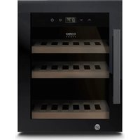
natural_image
Exterior view of a modern kitchen appliance with digital display and wooden shelves (no visible text or symbols)CE


Braukmann GmbH
Raiffeisenstraße 9
D-59757 Arnsberg
Service-Hotline International:
Tel.: +49 (0) 29 32 / 80 55 4 - 99
Fax: +49 (0) 29 32 / 80 55 4 - 77
eMail: kundenservice@caso-design.de
Internet: www.caso-design.de
Dokument-Nº: 07711 20-11-2020
10.3 Warning notices....38
10.4 Limitation of liability 39
10.5 Copyright protection ....39
11 Safety....39
11.1 Intended use....39
11.2 General Safety information ....40
11.3 Sources of danger 41
11.3.1 Risk of fire / flammable materials used. Danger of burns or of explosion .....41
11.3.2 Dangers due to electrical power 41
12 Commissioning 42
12.1 Safety information 42
12.2 Delivery scope and transport inspection....42
12.3 Unpacking....43
12.4 Disposal of the packaging....44
12.5 Setup....44
12.5.1 Setup location requirements: 44
12.6 How to open the door 45
12.7 Change of door stop....45
12.8 Installation in a kitchen uni....51
12.9 Overview....61
12.10 Shelves 62
12.10.1 Removal of Shelves....62
12.10.1 Wooden shelf with tipping equipment for presentation 63
12.11 Electrical connection....63
13 Operation and Handing....63
13.1 Operating elements and displays....63
13.2 Rating plate 64
14 Cleaning and Maintenance....64
14.1 Safety information 65
14.2 Cleaning....65
15 Troubleshooting....65
15.1 Safety notices....65
15.2 Fault indications and rectification of faults....66
16 Disposal of the Old Device....67
17 Guarantee....67
18 Technical Data....68
natural_image
Technical line drawing of a mechanical housing or enclosure with mounting flanges and internal compartments (no text or symbols)natural_image
Pure 3D line drawing of a rectangular prism with rounded ends and no text or symbolsnatural_image
Technical line drawing of a mechanical bracket or bracket (no text or symbols)- 2 Abstandshalter
Saugnapf

• Scharnierabdeckung PP1

natural_image
Simple line drawing of a rectangular frame with no text or symbols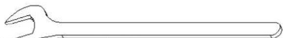
natural_image
Line drawing of a standard adjustable wrench (no text or symbols)• Schraubenschlüssel
HINWEIS
natural_image
Technical line drawing of a rectangular frame with a curved corner and an arrow indicating direction (no text or symbols)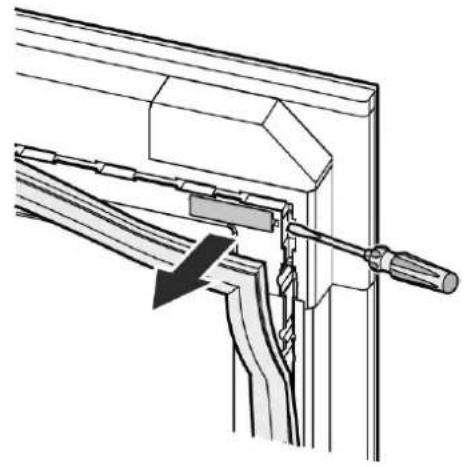
natural_image
Technical line drawing of a mechanical assembly with a lever and bracket (no text or symbols)natural_image
Technical diagram showing a mechanical assembly with a bracket and internal components, no visible text or symbolsnatural_image
Technical diagram of a mechanical assembly with two screwdrivers and a central shaft (no text or symbols)natural_image
Pure electrical connector pinout diagram without any text or symbols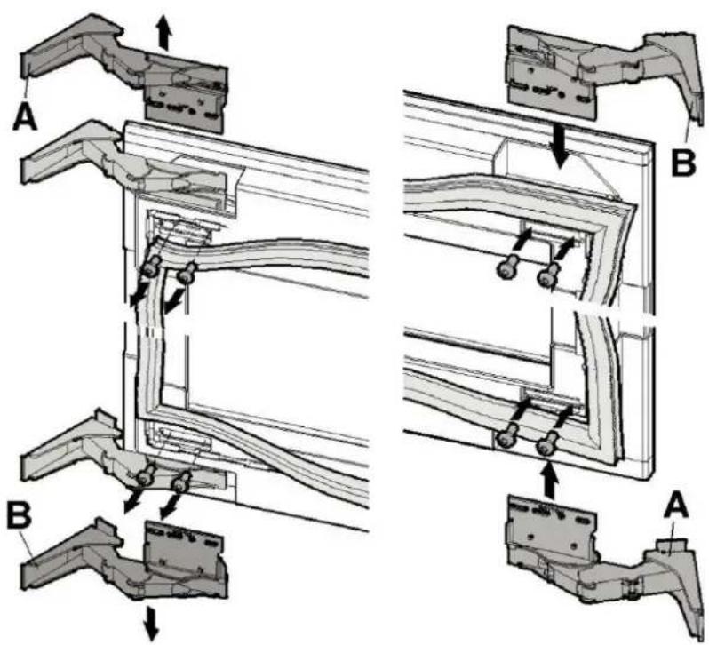

natural_image
Technical line drawing of a mechanical assembly with no visible text or symbolsnatural_image
Technical line drawing of a door frame with mounting brackets and directional arrows indicating movement (no text or symbols)⚠️WARNUNG
natural_image
Technical line drawing of a mechanical assembly with no visible text or symbolsnatural_image
Technical line drawing of a structural joint or bracket assembly (no text or symbols)natural_image
Diagram of a door or cabinet with directional arrows indicating movement or force (no text or symbols)natural_image
Diagram showing a mechanical assembly with a spring-loaded component and directional arrows indicating motion (no text or symbols)natural_image
Technical line drawing of an open refrigerator with ventilation grilles and a door, showing no text or symbols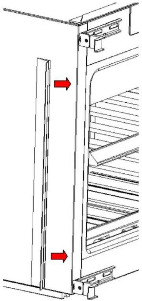
natural_image
Technical line drawing of a refrigerator interior with stairs and doorways, showing red directional arrows indicating movement (no text or symbols)natural_image
Technical line drawing of a mechanical assembly with no visible text or symbolsnatural_image
Technical line drawing of a door lock assembly with directional arrows indicating rotation (no text or symbols)natural_image
Technical diagram showing a bracket with an arrow pointing to a magnified detail of a rectangular component (no text or symbols present)natural_image
Technical line drawing of a mechanical assembly with two tools and a central component (no text or symbols)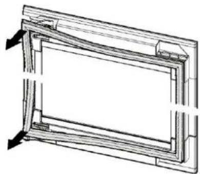
natural_image
Technical line drawing of a rectangular frame with internal structural details (no text or symbols)natural_image
Technical line drawing of a mechanical bracket assembly with an arrow indicating direction (no text or symbols present)natural_image
Technical line drawing of a metal rack or shelf with multiple supports and mounting holes (no text or symbols)natural_image
Technical line drawing of two mechanical components: a saw and a multi-cylindrical tray (no text or symbols)Original Operating Manual
WineDeluxe E 29 (7711)
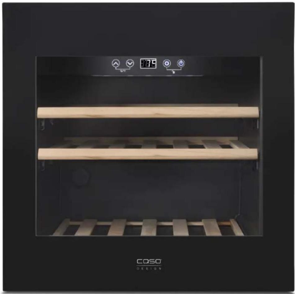
natural_image
Exterior view of a modern kitchen appliance with digital display and wooden shelves (no visible text or symbols)
10 Operating Manual
10.1 General
Please read the information contained herein so that you can become familiar with your device quickly and take advantage of the full scope of its functions.
Your wine refrigerator will serve you for many years if you handle it and care for it properly.
We wish you a lot of pleasure in using it!
10.2 Information on this manual
These Operating Instructions are a component of the WineDeluxe E 29 (referred to hereafter as the Device) and provide you with important information for the initial commissioning, safety, intended use and care of the device.
The Operating Instructions must be available at all times at the device. This Operating Manual must be read and applied by every person who is instructed to work with the device:
- Commissioning
- Operation
- Troubleshooting and/or
- Cleaning
Keep the Operating Manual in a safe place and pass it on to the subsequent owner along with the device.
10.3 Warning notices
The following warning notices are used in the Operating Manual concerned here.
⚠GEFAHR
DANGER
A warning notice of this level of danger indicates a potentially dangerous situation.
If the dangerous situation is not avoided, this can lead to death or serious injuries.
▶ Observe the instructions in this warning notice in order to avoid the danger of death or serious personal injuries.
▲WARNUNG
WARNING
A warning notice of this level of danger indicates a possible dangerous situation.
If the dangerous situation is not avoided, this can lead to serious injuries.
▶ Observe the instructions in this warning notice in order to avoid the personal injuries.
▲VORSICHT
ATTENTION
A warning notice of this level of danger indicates a possible dangerous situation.
If the dangerous situation is not avoided, this can lead to slight or moderate injuries.
▶ Observe the instructions in this warning notice in order to avoid the personal injuries.
HINWEIS
PLEASE NOTE
A notice of this kind indicates additional information, which will simplify the handling of the machine.
10.4 Limitation of liability
All the technical information, data and notices with regard to the installation, operation and care are completely up-to-date at the time of printing and are compiled to the best of our knowledge and belief, taking our past experience and findings into consideration. No claims can be derived from the information provided, the illustrations or descriptions in this manual. The manufacturer does not assume any liability for damages arising as a result of the following: • Non-observance of the manual
- Uses for non-intended purposes
- Improper repairs
- Technical alterations, modifications of the device
- Use of unauthorized spare parts
Modifications of the device are not recommended and are not covered by the guarantee.
All translations are carried out to the best of our knowledge. We do not assume any liability for translation errors, not even if the translation was carried out by us or on our instructions. The original German text remains solely binding.
10.5 Copyright protection
This document is copyright protected. Braukmann GmbH reserves all the rights, including those for photomechanical reproduction, duplication and distribution using special processes (e.g. data processing, data carriers, data networks), even partially. Subject to content and technical changes.
11 Safety
This chapter provides you with important safety notices when handling the device. The device corresponds with the required safety regulations. Improper use can result in personal or property damages.
11.1 Intended use
This device is only intended for use in households in enclosed spaces for cooling wine and other beverages. Uses for a different purpose or for a purpose which exceeds this description are considered incompatible with the intended or designated use.
▲WARNUNG WARNING
Danger due to unintended use!
Dangers can emanate from the device if it is used for an unintended use and/or a different kind of use.
▶ Use the device exclusively for its intended use.
▶ Observe the procedural methods described in this Operating Manual.
Claims of all kinds due to damages resulting from unintended uses are excluded.
The User bears the sole risk.
11.2 General Safety information
HINWEIS PLEASE NOTE
Please observe the following general safety notices with regard to the safe handling of the device.
▶ Examine the device for any visible external damages prior to using it. Never put a damaged device into operation.
▶ If the power cable or plug are damaged, then they must be replaced by the manufacturer or its service agent in order to avoid a hazard.
This device may be used by children aged 8 and above, if they are supervised or have been instructed at to the safe use of the device and have understood the resulting hazards.
▶ Cleaning and maintenance by the user must not be performed by children unless they are at least 8 years old and are supervised. Children are not allowed to play with the device.
▶ The device and its connecting cable must be kept away from children who are less than 8 years old.
The device may be used by individuals with reduced physical, sensory or mental capabilities or a lack of experience and / or knowledge of their use if they are supervised or have been instructed at to the safe use of the device and have understood the resulting hazards.
▶ Only customer service departments authorized by the manufacturer may carry out repairs on the device, as otherwise the guarantee entitlements will be null and void in the event of any subsequent damages. Improperly performed repairs can cause considerable dangers for the user.
▶ Defective components must always be replaced with original replacement parts. Only such parts will guarantee that the safety requirements are fulfilled.
11.3 Sources of danger
11.3.1 Risk of fire / flammable materials used. Danger of burns or of explosion
⚠️GEFAHR
DANGER
There is a danger of burns and explosion due to excess pressure that is created in the event the device is not used properly.
Observe the following safety notices to avoid dangers of burns or an explosion:
Warning: Risk of fire / flammable materials used.
▶ Do not store explosive substances such as aerosol cans with a flammable propellant in this device.
▶ Blowing gas inside the unit is flammable.
▶ Do not damage the cooling circuit of the device.
▶ Do not use electrical devices inside the device.
▶ Do not use mechanical devices or other means to accelerate the defrosting process.
▶ Never use the device to store or dry flammable materials.
▶ Never clean appliance parts with flammable fluids. The fumes can create a fire hazard or explosion.
▶ Do not store or use gasoline or any other flammable vapours and liquids in the vicinity of this or any other appliance. The fumes can create a fire hazard or explosion.
11.3.2 Dangers due to electrical power
⚠GEFAHR
Mortal danger due to electrical power!
Mortal danger exists when coming into contact with live wires or subassemblies!
Observe the following safety notices to avoid dangers due to electrical power:
⚠GEFAHR
DANGER
▶ Do not operate this device if it has a damaged cable or plug, if it is not working properly or if it has been damaged or dropped. If the power cable or plug are damaged, then they must be replaced by the manufacturer or its service agent in order to avoid a hazard.
▶ Do not open the housing on the device under any circumstances. There is a danger of an electrical shock if live connections are touched and the electrical or mechanical structure is altered. In addition, functional faults on the device can also occur.
12 Commissioning
This chapter provides you with important safety notices during the initial commissioning of the device. Observe the following notices to avoid dangers and damages:
12.1 Safety information
⚠️WARNUNG
WARNING
▶ Packaging materials may not be used for playing. There is a danger of suffocation.
▶ Transport, unpack and use two persons to set down the device because of the heavy weight of the device.
12.2 Delivery scope and transport inspection
As a rule, the WineDeluxe E 29 is delivered with the following components:
- WineDeluxe E 29 equipment for presentation
- 3 wooden bottoms + 1 wooden shelf with tipping
- Operating Instructions
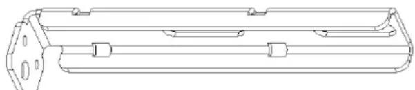
natural_image
Technical line drawing of a mechanical housing or enclosure component (no text or symbols)- 2 mounting brackets

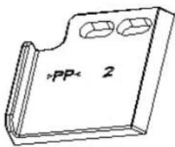
natural_image
Pure technical line drawing of a rectangular mechanical part (no text or symbols)• 2 covers for the mounting brackets
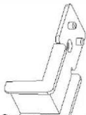
natural_image
Technical line drawing of a mechanical bracket or bracket (no text or symbols)• 2 spacers suction cup

- hinge cover PP1
- hinge cover PP2
- 6 screws
- Cover profile

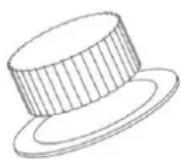
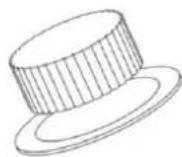
natural_image
Pure geometric line drawing of a rectangular prism (no text or symbols)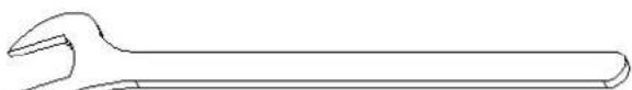
natural_image
Line drawing of a standard adjustable wrench (no text or symbols)- wrench
HINWEIS Please note
▶ Examine the shipment for its completeness and for any visible damages.
▶ Immediately notify the carrier, the insurance and the supplier about any incomplete shipment or damages as a result of inadequate packaging or due to transportation.
12.3 Unpacking
To unpack the device, proceed as follows:
Remove the device out of the carton and remove the packaging material.
Clean the interior surface with lukewarm water using a soft cloth.
Your device should only be moved in an upright position.
After at least 24 hours, plugging the appliance into the wall outlet, than place wine bottles or beverages in the appliance.
HINWEIS Please note
▶ Only remove the blue protective film shortly before setting up the device in the location where it will be used, to prevent scratches and dirt accumulations.
▲WARNUNG
Warning
▶ Caution, handle not installed device carefully as it could tip over if the door is opened.
12.4 Disposal of the packaging
The packaging protects the device against damages during transit. The packaging materials are selected in accordance with environmentally compatible and recycling-related points of view and can therefore be recycled.

Returning the packaging back to the material loop saves raw materials and reduces the quantities of accumulated waste. Take any packaging materials that are no longer required to “Green Dot” recycling collection points for disposal.
HINWEIS
Please note
▶ If possible, keep the original packaging for the device for the duration of the guarantee period of the device, in order that the device can be re-packaged properly in the event of a guarantee claim.
▶ Blowing gas inside the unit is flammable. The disposal of this flammable material should be in accordance with national regulations.
12.5 Setup
12.5.1 Setup location requirements:
In order to ensure the safe and trouble-free operation of the device, the setup location must fulfil the following prerequisites:
- Place your appliance on a flat, horizontal floor that is strong enough to support the appliance when it is fully loaded.
- Locate the appliance away from direct sunlight and sources of heat (stove, heater, radiator, etc.). Direct sunlight may affect the acrylic coating and heat sources may increase electrical consumption.
- This device is not designed for use in a garage or any other outside installation.
⚠️WARNUNG
Warning: Fire hazard due to moisture!
▶ If live parts or the power cord get wet, this can lead to short circuits.
The device is intended for use in closed rooms. Do not operate the device outdoors or in areas where it is exposed to splashing water or moisture.
- Do not set up the device in a hot, wet or extremely damp environment or near flammable material.
- WARNING! Do not close the ventilation openings in the device housing (and installation housing). When installing the device, leave openings for ventilation.
- The electrical socket must be easily accessible so that the power lead can be disconnected easily, in the case of an emergency.
- For energy saving reasons please ensure that the door is closed when the appliance is turned on.
12.6 How to open the door
- When the device is switched on, press on the glass of the door at the middle on top. The sensor reacts and the door opens a little. Then pull the door fully open by hand.
- If the device is not switched on or the plug is not plugged in, you need the supplied suction cup to open the door.
- Place the suction cup in the middle onto the glass at left side of the door and then carefully pull the door open a little. Then pull the door fully open by hand.
12.7 Change of door stop
Door hinges should only be changed by a trained specialist.
If you want to change the door hinge, you should do this BEFORE installation.
⚠️WARNUNG Warning: Risk of injury from heavy door
▶ Risk of injury and damage of property.
▶ Risk of injury if the door falls out! If the hinges are not screwed in properly, the door can fall out. This can lead to serious injuries.
HINWEIS Please note
▶ In addition, the door may not close properly and the device may not cool properly.
▶ Be careful when removing the screws so that they do not fall into the door frame.
1st step: Open the door
2^nd step: Remove the upper and lower hinge covers
3^rd step: Unsrew the screws at upper and lower hinge up to half thread length.
4^th step: Remove the door and lay it carefully on glass side on a soft surface so that the glass will not be damaged.
5th step: Remove the door gasket

natural_image
Technical line drawing of a rectangular frame with a curved internal structure and an arrow indicating direction (no text or symbols)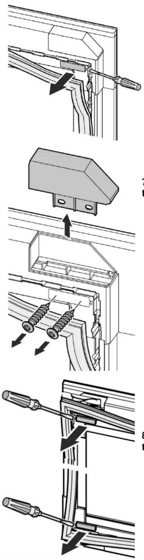
6^th step: Remove the elongated covers.
7^th step: Then unscrew the screws so that the cover of the hinge can be removed.
8th step: Remove the elongated covers at the side of the hinges.
9^th step: remove the upper left hinge and place at lower right position
Remove the lower left hinge and place at upper right position.
HINWEIS
Please note
The upper left hinge (A) becomes the lower right hinge at the new position. The lower left hinge (B) becomes the upper right hinge at the new position.
▶ Attention, put the screws back in the hinges in the same position as before.

10th step: Place cover of hinge at old position of hinge and fix it.

natural_image
Technical line drawing of a mechanical assembly with no visible text or symbols11 ^th step: Reinstall the small elongates covers on this side. The covers are of different length, please note and fit appropriately.
12^th step: Unscrew the screws on the device at the new position of the hinge up to half thread length.
13^th step: Place the door with its hinges on the screws. Fix the door and tighten the screws.
14 ^th step: Replace the door gasket
15 ^th step: Check that the door is fixed properly.
natural_image
Technical line drawing of a door frame with mounting brackets and directional arrows indicating movement (no text or symbols)⚠️WARNUNG
Warning
Risk of injury if the door falls out! If the hinges are not screwed properly, the door can fall out. This can lead to serious injuries.
natural_image
Technical line drawing of a mechanical assembly with no visible text or symbols16h step: Replace the elongated covers. The covers are of different length, please note and fit appropriately.
natural_image
Technical line drawing of a mechanical assembly with no visible text or symbols12.8 Installation in a kitchen uni
The kitchen cupboard must be aligned horizontally and vertically.
The cable is 1500 mm long. The socket must not be behind the device and must be easily accessible.
The device may only be installed by trained personnel. This requires two people.
Check the installation dimensions before installation.
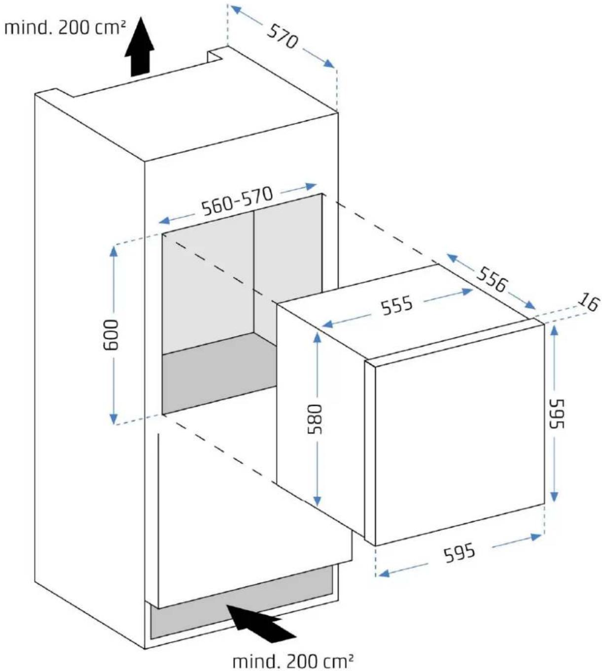
HINWEIS Please note
The funnel must be at least 200 cm^2 in size, from the lower ventilation opening up to the rear.
-
Insert the plug in the socket
-
Slowly push the device into the center of the kitchen cabinet until 2/3 of device is in it.
natural_image
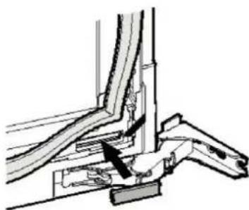
Diagram of a door frame with directional arrows indicating movement or force (no text or symbols)-
Do not pinch or kink the power cord.
-
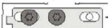
The screws that are located under the device at the front are for the adjusting of the device.

natural_image
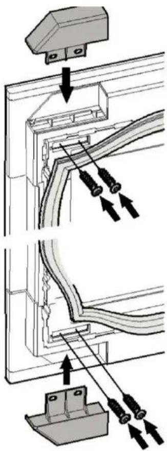
Diagram showing a mechanical assembly with a wrench and rotating component (no text or symbols)- Mount the spacer

- Remove the screws on the side which is facing away from the hinges
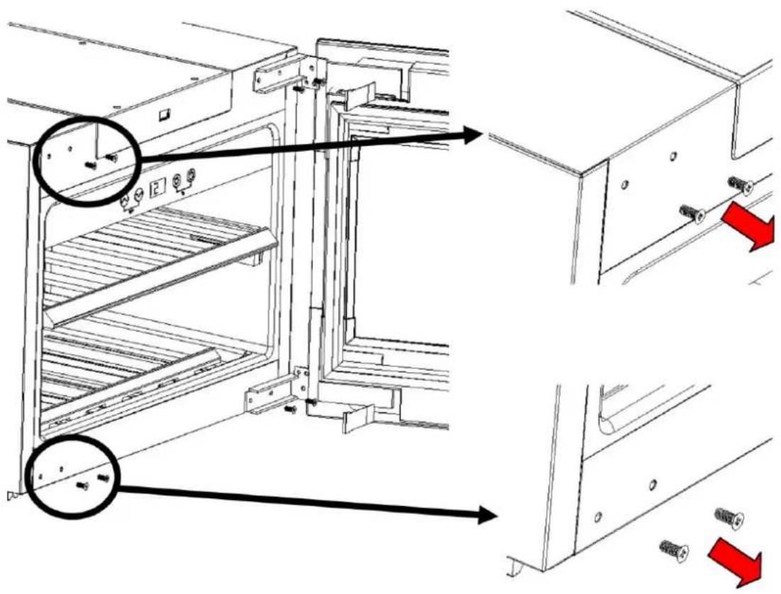
- Place the spacer on the mounting bracket and screw them together (depending on the door hinge correspondingly different position)

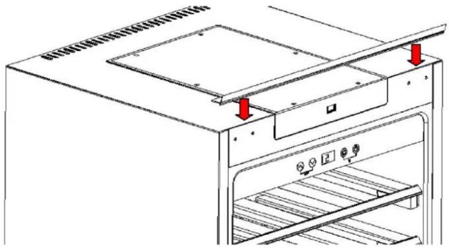
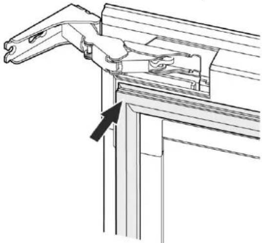
8. Mount the cover profile
Cut a cover profile for the top and one for the side. Then stick them on.
natural_image
Technical line drawing of a kitchen appliance with ventilation grilles and a door, showing no text or symbols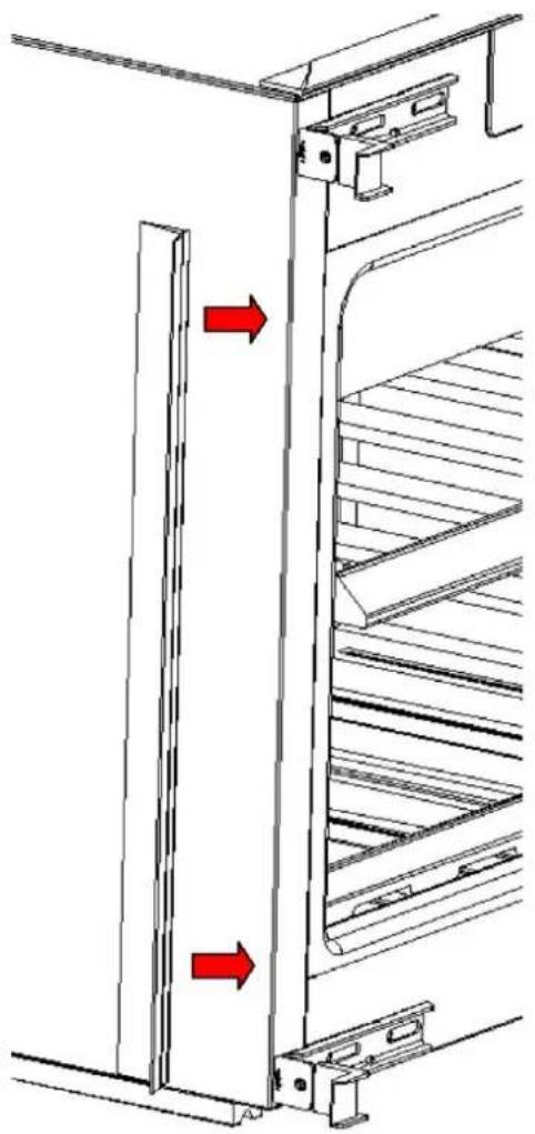
natural_image
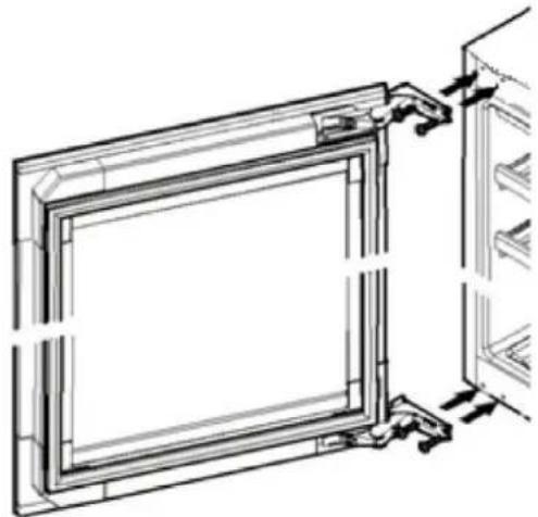
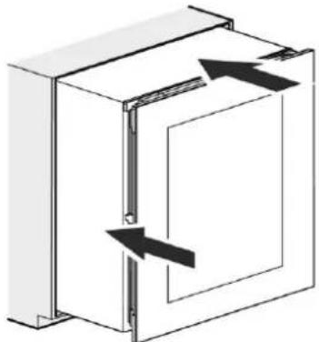
Technical line drawing of a refrigerator interior with shelves and doorways, showing red directional arrows indicating movement (no text or symbols)- Align the device with the screws.

natural_image
Technical line drawing of a mechanical assembly with no visible text or symbols10. Slide the device into the cabinet
Check that the distance around. The spacers help you to position the device flush mounted into the cabinet.
HINWEIS
Please note
▶ Caution: 2 mm space must be left between the door and the cabinet so that the automatic door opener can work.
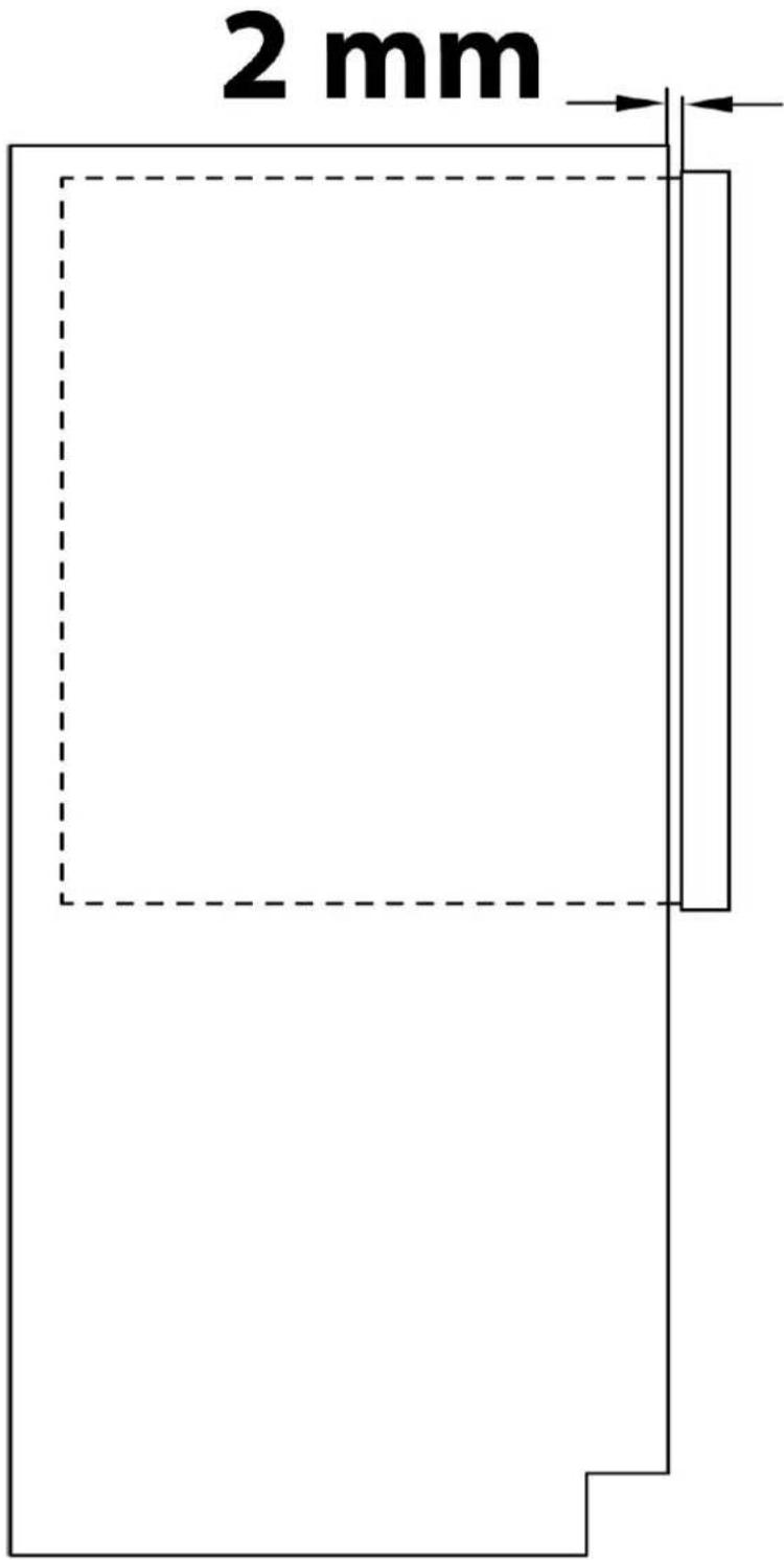
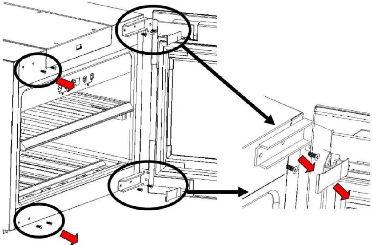
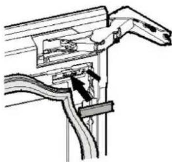
Loosen the screws (1). Slide the spacers to the side in direction of cabinet. Tighten the screws slightly so that you can still align the device.
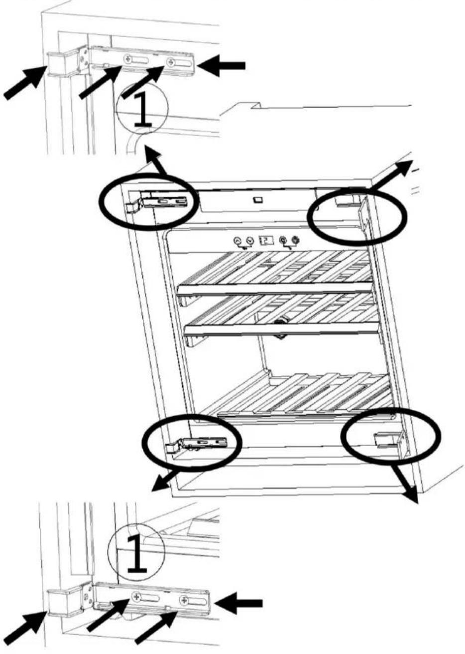
- Secure the device with screws through the hinges and the mounting brackets to the kitchen cabinet

- Break off and remove the front part of the spacer (X).

natural_image
Technical line drawing showing a door lock assembly with two side views and a cross-sectional view of the door (no text or symbols present)- Place the covers

natural_image
Technical diagram showing a bracket with an arrow pointing to a circular component (no text or symbols present)- Align the door, if needed

To do this, loosen the door gasket and the covers
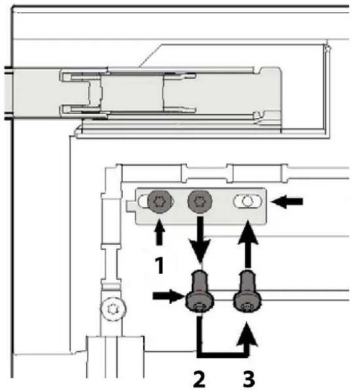
Then loosen the screws at position 2 and place them in position 3.
Loosen the screws at position 1.
Align the door.
Then tighten the screws at positions 1 and 3.

- Replace covers and gasket
natural_image
Technical line drawing of a mechanical bracket assembly with an arrow indicating direction (no text or symbols present)- Now screw the device in place
12.9 Overview

1 activated carbon filter
2 control panel
3 door opener
4 door
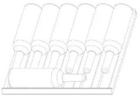
12.10 Shelves
Storage depending on kind of bottle and size. You can remove each shelf to store larger bottles.
natural_image
Technical line drawing of a mechanical assembly with multiple cylindrical components and a central shaft (no text or symbols)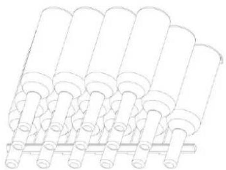
natural_image
Line drawing of multiple cylindrical components arranged in a row, no text or symbols presentUpper and middle shelf lower shelf
12.10.1 Removal of Shelves
To remove a shelf: Remove all bottles from the shelves.
Upper and middle shelf

natural_image
Technical line drawing of a mechanical rack or shelf assembly (no text or symbols)Carefully pull out the shelf with the rail as far as possible. Then lift the shelf at the front to detach it from the rail. Then pull the shelf to the front and thus detach it from the back of the rail.
Lower shelf:
Lift and remove.
HINWEIS
Please note
▶ Ensure that the shelves are firmly engaged in place before storing any bottles.
▶ Spread your bottles out as evenly as possible over the shelves, so weight is not concentrated in one point; and make sure your bottles will not touch the back of the cabinet.
⚠️WARNUNG
Warning
▶ Do not store bottles without an underlying shelf in the device.
▶ Otherwise, bottles may fall out when the appliance door is opened and this may cause injury or material damage.
12.10.1 Wooden shelf with tipping equipment for presentation
Example of storage: You can store or present Bordeaux bottles with a height of 310 mm and a diameter of 75 mm as follows:
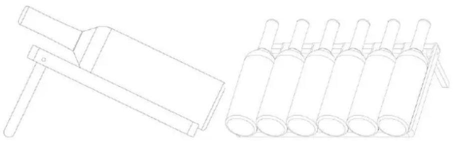
natural_image
Technical line drawing of two mechanical components: a tool and a multi-cylindrical tray (no text or symbols)12.11 Electrical connection
In order to ensure the safe and trouble-free operation of the device, the following instructions must be observed for the electrical connection:
- Before connecting the device, compare the connection data (voltage and frequency) on the rating plate with those of your electrical network. This data must agree in order that no damages occur in the device. If in doubt, ask your qualified electrician.
- The connection between the device and the electrical network may employ a 3 meter long (max.) extension cable with a cross-section of 1.5 mm ^2 . The use of multiple plugs or gangs is prohibited because of the danger of fire that is involved with this.
- Make sure that the power cable is undamaged and has not been installed under or over hot or sharp surfaces.
- This device is not designed to be installed in an RV or used with an inverter.
- The electrical outlet must be protected by a 16A safety cut-out switch.
- The electrical safety of the device is only guaranteed if the device is connected to a properly installed protective conductor system. If in doubt, have the house installation checked over by a qualified electrician. The manufacturer cannot be made responsible for damages that are caused by a missing or damaged protective conductor.
13 Operation and Handing
This chapter provides you with important notices with regard to operating the device.
13.1 Operating elements and displays
The device transmits the following signal sounds as an acoustic feedback signal:
HINWEIS
Please note
▶ Use the buttons and to set the temperature in the range of 5-20°C.
▶ Temperature recommendations: Red wine: 12^ C – 18^ C and white wine 6^ C – 10^ C.
The device can achieve the best cooling and consumption results at a recommended ambient temperature of 16-20 °C.
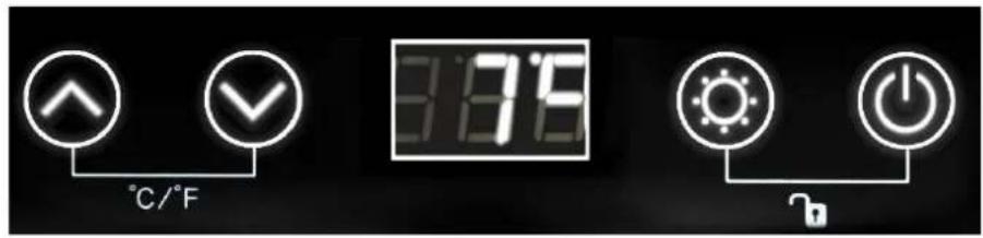

If you press the power button the device starts working.
With pushing both for ends, the temperature display mode will be exchange between ^ C and ^ F.
You can set the temperature as your desire: With and you can adjust the temperature by 1°C among 5-20°C.
You can activate or deactivate the childproof lock by pressing the button simultaneously for 5 seconds. If the childproof lock is active, no input possible.

You can tune the interior light on or off by pressing the "Light" button. The light will off automatically after 4 hours to save energy.
The temperature in the device depends on the room temperature, the quantity of bottles and the chosen temperature. Please note that your device is intended to cool wine. The maximum temperature that can be reached inside the device
13.2 Rating plate
The rating plate with the connection and performance data can be founded on the back of the device.
14 Cleaning and Maintenance
This chapter provides you with important notices with regard to cleaning and maintaining the device. Please observe the notices to prevent damages due to cleaning the device incorrectly and to ensure trouble-free operation.
14.1 Safety information
▲VORSICHT Attention
Please observe the following safety notices, before you commence with cleaning the device:
▶ Prior to commissioning, clean the appliance thoroughly.
▶ Switch the device off prior to cleaning it and unplug the plug from the wall power outlet. Remove all content.
▶ Do not use any aggressive or abrasive cleaning agents or solvents.
▶ Do not scrape off stubborn dirt with hard items.
14.2 Cleaning
◆ Interior space
- Wash the inside with a damp cloth soaked in lukewarm water and a bit of mild detergent.
- Tip for neutralisation of odors: Wash the inside with a damp cloth soaked in lukewarm water and baking soda solution. The solution should be about 2 tablespoons of baking soda to a quarter of water.
- After cleaning the interior space, leave the oven door open until the interior of the device is completely dry.
◆ Door gasket
- Be sure to keep the door gasket clean to keep the unit running efficiently.
◆ Activated carbon filter
- Replace the activated carbon filter once a year. To do this, remove all bottles, unscrew the filter and replace it.
15 Troubleshooting
This chapter provides you with important notices with regard to operating the device. Observe the following notices to avoid dangers and damages:
15.1 Safety notices
▲VORSICHT Attention
▶ Only qualified electricians, who have been trained by the manufacturer, may carry out any repairs on electrical equipment.
▶ Improperly performed repairs can cause considerable dangers for the user and damages to the device.
15.2 Fault indications and rectification of faults
The following table assists in localizing and rectifying minor faults.
| Fault | Possible Cause |
| Wine refrigerator is not cold enough. | Check the temperature control setting.External environment may require a higher setting.The door is open too often.The door is not closed completely.The door seal does not seal properly.The wine refrigerator does not have the correct clearance. |
| The light does not work. | Contact customer service |
| Vibrations & too much noise & door does not close properly | Check to assure that the wine refrigerator is level. Check the fan. Components are loose. The door is reversed and not properly installed.The seal is weak. The shelves are out of position. |
| LED could not display.LED display error – LoButtons are not functional | Contact customer service |
| Compressor will not start | Room temperature is lower than desired temperature. |
| Dew on the surface of cabinet : | The surface of wine cabinet especially the glass door appear some frost if item in a damp room. This is due to the moisture in the air coming into contact with the cabinet.Please wipe it away with dry cloth. |
| Liquid sound | 1) The sound of compressor when starts or stops working2) The flowing sound of refrigerant in the refrigeration system3) The evaporating sound of refrigerant in the evaporator |
| Condensation formed inside the cabinet | Under the environment with high level of humidity or the door of wine cabinet has been left open for a long period or opened frequently, wipe off the door. Open the door as rarely as possible. |
| Error code E2 | Desired temperature is not reached.Contact customer service. |
HINWEIS
Please note
▶ If you are unable to solve the problem with the steps shown above, please contact Customer Service.
16 Disposal of the Old Device
Old electric and electronic devices frequently still contain valuable materials. However, they also contain damaging substances, which were necessary for their functionality and safety.
If these were put in the non-recyclable waste or were handled incorrectly, they could be detrimental to human health and the environment. Therefore, do not put
your old device into the non-recyclable waste under any circumstances.
HINWEIS Please note
▶ Utilise the collection point, established in your town, to return and recycle old electric and electronic devices. If necessary, contact your town hall, local refuse collection service or your dealer for information.
▶ Ensure that your old device is stored safely away from children until it is taken away: Before you throw away your old refrigerator take off the doors and leave the shelves in place, so that children may not easily climb inside.
▶ Blowing gas inside the unit is flammable. The disposal of this flammable material should be in accordance with national regulations.
17 Guarantee
We provide a 24 month guarantee for this product, commencing from the date of sale, for faults which are attributable to production or material faults.
Your legal guarantee entitlements in accordance with § 439 ff. BGB-E remain unaffected by this.
The guarantee does not include damages, which were incurred as a result of improper handling or use, as well as malfunctions which only have a minor effect on the function or the value of the device. Consumables, transit damages, inasmuch as we are not responsible for these, as well as damages, which were incurred as a result of any repairs that were not performed by us, are also excluded from the guarantee entitlements.
This device is designed for use in domestic situations and has the appropriate performance levels.
Any use in commercial situations is only covered under the guarantee to the extent that it would be comparable with the stresses of being used in a domestic situation. It is not intended for any additional, commercial use.
In the event of justified complaints, we will repair the faulty device at our discretion or replace it with a trouble-free device.
Any pending faults must be reported within 14 days of delivery.
All further claims are excluded.
To enforce a guarantee claim, please contact us prior to returning the device (always provide us with proof of purchase).
18 Technical Data
| Name | WineDeluxe E 29 (7711) |
| Power | 85W |
| Power consumption in 24 hours in kWh | 0,39 (12°C) |
| Connection | 220V-240V;50Hz |
| External measurements (W x H x D) | 595 x 595 x 572 mm |
| Capacity | 29 bottles |
| Weight | 39,10 kg |
| Climate class | ST |


- Braukmann GmbH
- HINWEIS
- ⚠️WARNUNG
- Original Operating Manual
- Operating Manual
- General
- Information on this manual
- Warning notices
- ⚠GEFAHR
- DANGER
- ▲WARNUNG
- WARNING
- ▲VORSICHT
- ATTENTION
- PLEASE NOTE
- Limitation of liability
- Copyright protection
- Safety
- Intended use
- ▲WARNUNG WARNING
- Danger due to unintended use!
- General Safety information
- HINWEIS PLEASE NOTE
- Please observe the following general safety notices with regard to the safe handling of the device.
- Sources of danger
- Risk of fire / flammable materials used. Danger of burns or of explosion
- ⚠️GEFAHR
- Warning: Risk of fire / flammable materials used.
- Dangers due to electrical power
- Commissioning
- Safety information
- Delivery scope and transport inspection
- Unpacking
- Disposal of the packaging
- Setup
- Setup location requirements:
- Warning: Fire hazard due to moisture!
- How to open the door
- Change of door stop
- ⚠️WARNUNG Warning: Risk of injury from heavy door
- Installation in a kitchen uni
- Mount the cover profile
- Slide the device into the cabinet
- Shelves
- Removal of Shelves
- Upper and middle shelf
- Lower shelf:
- Wooden shelf with tipping equipment for presentation
- Electrical connection
- Operation and Handing
- Operating elements and displays
- Rating plate
- Cleaning and Maintenance
- Safety information
- ▲VORSICHT Attention
- Cleaning
- ◆ Interior space
- ◆ Door gasket
- ◆ Activated carbon filter
- Troubleshooting
- Safety notices
- Fault indications and rectification of faults
- Disposal of the Old Device
- Guarantee
Brand : CASO
Model : WineDeluxe E29
Category : Wine cellar