
CJ 65S3 - Saw HITACHI - Free user manual and instructions
Find the device manual for free CJ 65S3 HITACHI in PDF.


| Product Type | Jigsaw (Sabre Saw) |
| Model Number | CJ 65S3 |
| Brand | Hitachi |
| Power Input | 400 W |
| Rated Voltage | 110-240 V AC (depending on region) |
| No-Load Speed | 3000 min⁻¹ (fixed speed) |
| Stroke Length | 18 mm |
| Max. Cutting Depth (Wood) | 65 mm |
| Max. Cutting Depth (Mild Steel) | 6 mm |
| Min. Cutting Radius | 25 mm |
| Weight (without cord) | 1.5 kg |
| Blade Type | Standard blades with shank thickness ≤1.6 mm, width up to 8 mm |
| Guide Roller | Adjustable; use with blades having straight rear edge >50 mm |
| Chip Cover | 3-position adjustable to reduce dust and chip dispersal |
| Splinter Guard | Included for cleaner cuts in wood |
| Base Tilt | Adjustable for angled cuts (0-45°) |
| Power Cord | Detachable, replaceable by authorized service center |
| Standard Accessories | Blade No.31, splinter guard, chip cover, hexagonal bar wrench |
| Optional Accessories | Blades No.1-6, 31; guide attachment |
| Maintenance | Regular inspection of blade, screws, and motor; use genuine Hitachi parts |
| Safety Features | Double insulation, lock-off switch, blade guard, chip cover |
Frequently Asked Questions - CJ 65S3 HITACHI
User questions about CJ 65S3 HITACHI
0 question about this device. Answer the ones you know or ask your own.
Ask a new question about this device
Download the instructions for your Saw in PDF format for free! Find your manual CJ 65S3 - HITACHI and take your electronic device back in hand. On this page are published all the documents necessary for the use of your device. CJ 65S3 by HITACHI.
USER MANUAL CJ 65S3 HITACHI
natural_image
Technical line drawing of a mechanical device with internal components and a cable (no text or symbols)CJ 65V3
Read through carefully and understand these instructions before use.
(b)(a)
2
3
4
5
6
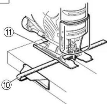
7
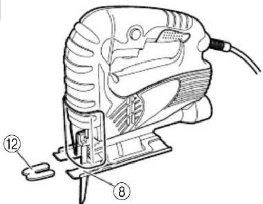
8
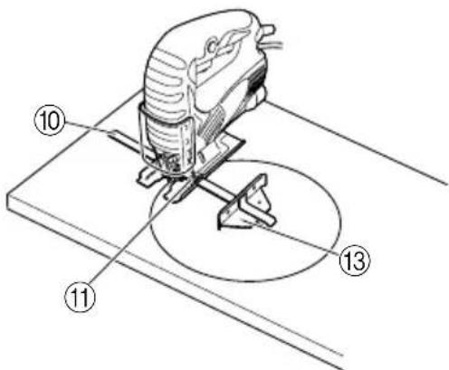
9
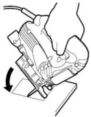
natural_image
Diagram of a hand operating a mechanical device with a rotating arrow indicating rotation (no text or symbols present)10
natural_image
Line drawing of a hand using a tool to cut or cutter through a mechanical component (no text or symbols)11
12
13
natural_image
Technical line drawing of a mechanical device with no visible text or symbols14
| English Deutsch Eλληνικά Polski | ||||
| 1 | Blade holder Sägeblatthalter | Στήριγμα λεπίδας | Uchwyt ostrza | |
| 2 | Hexagonal bar wrench Sechskantinnenschlüssel | Εξάγωνο κλειδί Άλεν | Klucz sześciokątny | |
| 3 | Blade (blade edge must Sägeblatt (Schnittfläche face front) muß nach vorne zeigen) | Λεπίδα (η κόψη της λεπίδας πρέπει να βλέπει μπροστά) | Ostrze (krawędź ostrza musi być skierowana do przodu) | |
| 4 | Blade set screw | Klemmschraube für das Sägeblatt | Βίδα λεπίδας | Śruba mocująca ostrze |
| 5 | Roller Führungsrolle | Κύλινδρος | Walek | |
| 6 | Holder Halter | Στήριγμα | Uchwyt | |
| 7 | Main unit Hauptgerät | Κύρια μονάδα | Jednostka główna | |
| 8 | Base Sägetisch | Βάση | Podstawa | |
| 9 | Chip cover Schnipseldeckel | Κάλυμμα ρινισμάτων | Osłona zabezpieczająca przed odłamkami | |
| 10 | Guide Führungsrolle | Οδηγός | Prowadnica | |
| 11 | 4mm screw (8mm) 4mm Schraube (8mm) | Βίδα 4mm (8mm) | Śruba 4mm (8mm) | |
| 12 | Splinter guard Splitterschutz | Προφυλακτήρας σχίζας | Osłona zabezpieczająca przed odpryskami | |
| 13 | Nail or wood screw Nagel oder Holzschraube | Καρφί ή βίδα ξύλου | Gwóźdź lub wkręt do drewna | |
| 14 | Scale | Skala | Κλίμακα | Podziałka |
| 15 | Side groove | Seitlicher Schlitz | Πλευρική εγκοπή | Rowek boczny |
| 16 | Housing edge line | Gehäusekante | Οδηγός στερέωσης | Linia krawędzi obudowy |
| 17 | Hose attachment part | Schlauchanschluss | Τμήμα στερέωσης του λάστιχου | Elementem przyłącza weża |
| 18 | Acceptable blades | Schlauchanbringungsbereich | Αποδεκτές λεπίδες | Odpowiednie ostrza |
| Magyar Čeština Türkçe Русский | ||||
| 1 | Fűrészlap befogószerkezet | Držák listu | Bıçak tutucu | Держатель полотна |
| 2 | Hatszögletű dugókulcs | Klíč na vnitřní šestihrany | Alyan anahtarı | Гаечный ключ в виде шестигранного стержня |
| 3 | Fűrészlap (a fűrészlap élének előrefelé kell néznie) | Plátek (Ostří plátku musí směřovat dopředu) | Bıçak (bıçağın keskin kenarı ön tarafa bakmalı) | Полотно (край полотна должен быть обращен вперед) |
| 4 | Fűrészlap-hernyócsavar | Stavěcí šroub plátku | Bıçak ayar vidası | Установочный винт полотна |
| 5 | Henger | Vodicí kladka | Silindir | Ролик |
| 6 | Tartó | Držák | Tutamaç | Держатель |
| 7 | Fő egység | Hlavní jednotka | Ana ünite | Основной корпус |
| 8 | Alapzat | Základní deska | Taban | Основание |
| 9 | Forgácsvédő fedél | Kryt proti třískám | Talaş/yonga kapağı | Крышка стружкосборника |
| 10 | Vezetőelem | Vedení | Kılavuz | Направляющая |
| 11 | 4mm-es csavar (8mm) | Šroub 4mm (8mm) | 4mm’lík vida (8mm) | 4-мм винт (8 мм) |
| 12 | Forgácsvédő pajzs | Ochranný kryt proti odštěpování | Kıymık muhafazası | Защитное приспособление |
| 13 | Szeg vagy facsavar | Hřebík nebo vrut do dřeva | Çivi veya ahşap vidası | Гвоздь или шуруп |
| 14 | Skála | Stupnice | Ölçek | Шкала |
| 15 | Oldalsó horony | Boční drážka | Kenar oluşu | Боковая канавка |
| 16 | Burkolat szélső vonal | Vodící proužek pouzdra | Gövde kenar çizgisi | Граница кромки корпуса |
| 17 | Cső tartozék alkatrészhez. | Části k připojení hadice | Hortum takma ucuna | Крепежной деталью рукава |
| 18 | Elfogadható fűrészlapok | Povolené řezné plátky | Kabul edilebilir bıçaklar | Применимые полотна |
GENERAL SAFETY RULES
WARNING!
Read all instructions
Failure to follow all instructions listed below may result in electric shock, fire and/or serious injury.
The term “power tool” in all of the warnings listed below refers to your mains operated (corded) power tool or battery operated (cordless) power tool.
SAVE THESE INSTRUCTIONS
1) Work area
a) Keep work area clean and well lit.
Cluttered and dark areas invite accidents.
b) Do not operate power tools in explosive atmospheres, such as in the presence of flammable liquids, gases or dust.
Power tools create sparks which may ignite the dust of fumes.
c) Keep children and bystanders away while operating a power tool.
Distractions can cause you to lose control.
2) Electrical safety
a) Power tool plugs must match the outlet.
Never modify the plug in any way.
Do not use any adapter plugs with earthed (grounded) power tools.
Unmodified plugs and matching outlets will reduce risk of electric shock.
b) Avoid body contact with earthed or grounded surfaces such as pipes, radiators, ranges and refrigerators.
There is an increased risk of electric shock if your body is earthed or grounded.
c) Do not expose power tools to rain or wet conditions.
Water entering a power tool will increase the risk of electric shock.
d) Do not abuse the cord. Never use the cord for carrying, pulling or unplugging the power tool. Keep cord away from heat, oil, sharp edges or moving parts.
Damaged or entangled cords increase the risk of electric shock.
e) When operating a power tool outdoors, use an extension cord suitable for outdoor use.
Use of a cord suitable for outdoor use reduces the risk of electric shock
3) Personal safety
a) Stay alert, watch what you are doing and use common sense when operating a power tool.
Do not use a power tool while you are tired or under the influence of drugs, alcohol or medication.
A moment of inattention while operating power tools may result in serious personal injury.
b) Use safety equipment. Always wear eye protection.
Safety equipment such as dust mask, non-skid safety shoes, hard hat, or hearing protection used for appropriate conditions will reduce personal injuries.
c) Avoid accidental starting. Ensure the switch is in the off position before plugging in.
Carrying power tools with your finger on the switch or plugging in power tools that have the switch on invites accidents.
d) Remove any adjusting key or wrench before turning the power tool on. A wrench or a key left attached to a rotating part of the power tool may result in personal injury.
e) Do not overreach. Keep proper footing and balance at all times.
This enables better control of the power tool in unexpected situations.
f) Dress properly. Do not wear loose clothing or jewellery. Keep your hair, clothing and gloves away from moving parts.
Loose clothes, jewellery or long hair can be caught in moving parts.
g) If devices are provided for the connection of dust extraction and collection facilities, ensure these are connected and properly used.
Use of these devices can reduce dust related hazards.
4) Power tool use and care
a) Do not force the power tool. Use the correct power tool for your application.
The correct power tool will do the job better and safer at the rate for which it was designed.
b) Do not use the power tool if the switch does not turn it on and off.
Any power tool that cannot be controlled with the switch is dangerous and must be repaired.
c) Disconnect the plug from the power source before making any adjustments, changing accessories, or storing power tools.
Such preventive safety measures reduce the risk of starting the power tool accidentally.
d) Store idle power tools out of the reach of children and do not allow persons unfamiliar with the power tool or these instructions to operate the power tool.
Power tools are dangerous in the hands of untrained users.
e) Maintain power tools. Check for misalignment or binding of moving parts, breakage of parts and any other condition that may affect the power tools operation.
If damaged, have the power tool repaired before use.
Many accidents are caused by poorly maintained power tools.
f) Keep cutting tools sharp and clean.
Properly maintained cutting tools with sharp cutting edges are less likely to bind and are easier to control.
g) Use the power tool, accessories and tool bits etc., in accordance with these instructions and in the manner intended for the particular type of power tool, taking into account the working conditions and the work to be performed.
Use of the power tool for operations different from intended could result in a hazardous situation.
5) Service
a) Have your power tool serviced by a qualified repair person using only identical replacement parts.
This will ensure that the safety of the power tool is maintained.
PRECAUTION
Keep children and infirm persons away.
When not in use, tools should be stored out of reach of children and infirm persons.
SPECIFICATIONS
| Model CJ65V3 CJ65S3 | ||
| Voltage (by areas)* (110V, 115V, 120V, 127V, 220V, 230V, 240V) | ||
| Power input 400W* | ||
| Max. cutting depth | Wood: 65mmMild steel: 6mm | |
| No-load speed 0 – 3000 min | -1 | 3000 min^-1 |
| Stroke 18mm | ||
| Min. cutting radius 25mm | ||
| Weight (without cord) 1.5kg | ||
* Be sure to check the nameplate on product as it is subject to change by areas.
STANDARD ACCESSORIES
(1) Blade No.31 .... 1
For cutting thick lumber
(2) Splinter guard 1
(3) Chip cover 1
(4) Hexagonal bar wrench 1
Standard accessories are subject to change without notice.
OPTIONAL ACCESSORIES (sold separately)
(1) Blades, No.1 - No.6, 31*
* No.31 Blade is a standard accessory.
(2) Guide
Optional accessories are subject to change without notice.
APPLICATIONS
○Cutting various lumber and pocket cutting
○Cutting mild steel plate, aluminum plate, and copper plate
○Cutting synthetic resins, such as phenol resin and vinyl chloride
○Cutting thin and soft construction materials
PRIOR TO OPERATION
1. Power source
Ensure that the power source to be utilized conforms to the power requirements specified on the product nameplate.
2. Power switch
Ensure that the power switch is in the OFF position. If the plug is connected to a receptacle while the power switch is in the ON position, the power tool will start operating immediately, which could cause a serious accident.
3. Extension cord
When the work area is removed from the power source, use an extension cord of sufficient thickness and rated capacity. The extension cord should be kept as short as practicable.
MOUNTING THE BLADE
-
Use the accessory hexagonal bar wrench to loosen the blade set screws on the blade holder, as shown in Fig. 1(a).
-
Holding the blade with its cutting edge facing the front, insert the mounting portion of the blade into the plunger groove until it touches the bottom of the groove.
- As shown in Fig. 1(b), firmly clamp the side screw.
○Loosened set screws may cause the blade to be damaged. Always ensure that the set screws are securely tightened. Always ensure that the plunger groove is clean and clear of sawdust to ensure proper blade mounting and set screw clamping. - Storing the hexagonal bar wrench
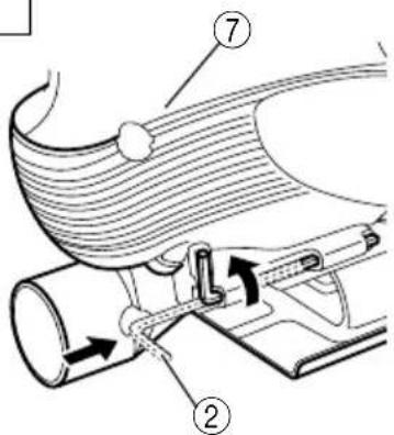
(1) Insert in a hole on the side of the main unit with holding the short side horizontally as shown in Fig. 2.
(2) Rotate with the hexagonal bar wrench inserted and secure as shown in Fig. 2.
CAUTION
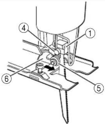
The guide roller, shown in Fig. 3, is employed to prevent the blade from snapping. Prior to use, adjust guide roller in accordance with the following procedures:
(1) Loosen the holder set screw with the accessory hexagonal bar wrench.
(2) Gently slide the guide roller until the roller groove lightly touches the back of the blade.
NOTE
On delivery from the factory, there is a gap of about 3mm between the roller and blade.
(3) Firmly tighten the holder set screw.
CAUTION
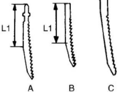
The guide roller can be used only for Blades that have a straight line on the rear that is longer than 50mm. (Fig. 4A and 4B) When using other types of blades (Fig. 4C), slide the guide roller in backwards so that the guide roller does not contact the blade.
When cutting thick boards or performing continuous cutting operations, use the blade shown in the Fig. 4A, 4B and be sure to set the guide roller.
CHIP COVER POSITIONING
1. Chip cover
Use the chip cover to reduce flying of cut particles and to easily operate the saw.
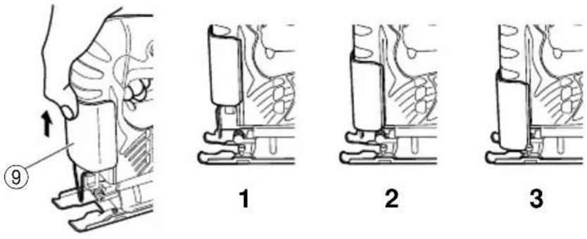
Slide the chip cover while lightly pressing its front section.
The chip cover can be set at three positions as shown in Fig. 5.
2. How to choose the position of the ship cover
Set the chip cover to the first step when attaching or removing the blade.
Set the chip cover to the second step when cutting wooden materials.
Set the chip cover to the second or third step when cutting metal materials such as steel.
CAUTION
- Keep always the chip cover in the low position when operating the tool.
○Wear protection glasses even if the chip cover is used.
ADJUSTING THE BLADE OPERATING SPEED .... (CJ65V3 only)
NOTE
The blade operating speed cannot be adjusted for CJ65S3.
The blade operating speed can be adjusted within a range of 0 to 3,000 min ^-1 according to the degree that the trigger switch is depressed. Select the speed appropriate to the material being worked and/or the working conditions.
To achieve continuous operation, pull the trigger switch all the way back and depress the stopper. Then, turn the speed adjustment knob to adjust the blade operating speed as desired.
NOTE
The speed adjustment knob rotates approximately 1.5 turns. To turn the switch OFF, pull the trigger switch again to disengage the stopper, and release the trigger switch.
CUTTING
CAUTION
While sawing, the base must be firmly in contact with the material surface, and the blade must be held at a right angle. If the base becomes separated from the material, it could cause the blade to break.
○When cutting while holding the front surface, be careful of the moving blade and hold the upper part firmly.
1. Rectilinear cutting
(1) To ensure accurate rectilinear cutting, employ the optional accessory guide as shown in Fig. 6.
(2) Use the splinter guard to reduce roughness of the cutting surface of wooden materials. Attach the splinter guard by inserting it from the front section of the base until it clicks into place. (Fig. 7)
CAUTION
Set the base in the front position when using the splinter guard.
2. Cutting a circle or a circular arc
To ensure efficient cutting, employ the optional accessory guide and nail or wood screw as shown in Fig. 8.
When mounting the guide, loosen the base bottom screw, and shift the base as far forward as it will go.
3. Sawing curved lines
When sawing a small circular arc, reduce the feeding speed of the machine. If the machine is fed too fast, it could cause the blade to break.
4. Cutting metallic materials
Always use an appropriate cutting agent (spindle oil, soapy water, etc.). When a liquid cutting agent is not available, apply grease to the back surface of the material to be cut.
5. Pocket cutting
(1) In lumber
Aligning the blade direction with the grain of the wood, cut step by step until a window hole is cut in the center of the lumber. (Fig. 9)
(2) In other materials
When cutting a window hole in materials other than lumber, initially bore a hole with a drill or similar tool from which to start cutting.
6. Angular cutting
Set the chip cover to the first step. (Fig. 5)
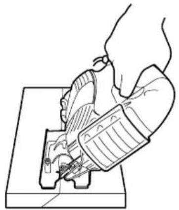
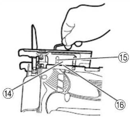
To adjust the angle of inclination; loosen the base bottom screw, shift the base position to the side groove of the semicircular portion, align the scale on the base semicircular portion (figures engraved on the scale indicate the angle of inclination) with the housing edge line, and thoroughly tighten the base bottom screw. (Fig. 10 and 11)
CAUTION
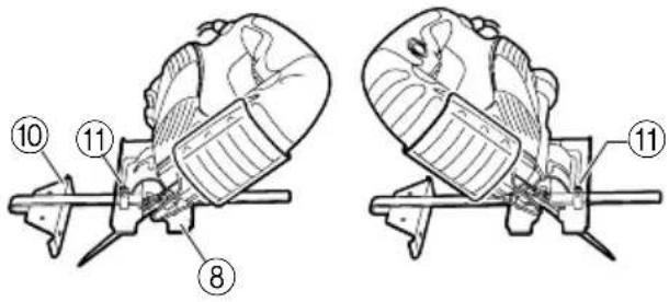
Set the screw to the opposite side of the inclining side when using the guide. (Fig. 12)
7. Dust produced in operation
CAUTION
To prevent accidents, turn the switch off and remove the plug from the power supply when not in use.
☐For instruction on using the dust collector and applicable cutting debris, please read the dust collector instruction manual.
The dust produced in normal operation may affect the operator's health. Either of following way is recommended.
a) Wear a dust mask
b) Use external dust collection equipment
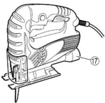
When using the external dust collection equipment, connect the rubber adapter (accessory of external dust collection equipment) with end the of hose from external dust collection equipment.
Then connect the another end of rubber adapter with the hose attachment part that positioned in rear end of jig saw. (See Fig. 13)
SELECTION OF BLADES
1. Accessory blades
To ensure maximum operating efficiency and results it is very important to select the appropriate blade best suited to the type and thickness of the material to be cut. One type of blade is provided as standard accessory. The blade number is engraved in the vicinity of the mounting portion of each blade. Select appropriate blades by referring to Table 1.
Table 1 List of Appropriate Blades
| Material to be cut Material quality Blade No. | ||
| Lumber | General lumber | No.1 or No.31 (thick plate) or No.41 (thick plate) or No.2 (thin plate) |
| Plywood No.3 or No.6 | ||
| Iron plate Mild steel plate No.6 | ||
| Nonferrous metal Aluminum num, copper, brass No.6 | ||
| Synthetic resin | Phenol resin, melamine resin, etc. No.4 (thick plate) or No.6 (thin plate) | |
| Vinyl chloride, acryl resin, etc. | No.2 or No.4 (thick plate) or No.6 (thin plate) | |
| Foamed styrol, etc. No.2 | ||
| Pulp | Cardboard, corrugated paper No.2 | |
| Hardboard No.5 or No.6 | ||
| Fiberboard No.6 | ||
| Others | Hard rubber No.2 | |
| Slate No.5 | ||
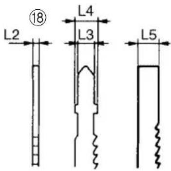
2. Acceptable commercial blades (Fig. 14)
This machine is designed to accept most blades available on the open market. As illustrated in Fig. 14, blade dimension restrictions are as follows:
○ Thickness: L2 ..... Less than 1.6mm
○ Width : L3 ..... 6.3mm
L4 ..... 8mm
L5 ..... 7mm
NOTE
When cutting thick materials, use HITACHI genuine blades which have an inclination as shown in Fig. 4-A or B.
MAINTENANCE AND INSPECTION
1. Inspecting the blade
Continued use of a dull or damaged blade will result in reduced cutting efficiency and may cause overloading of the motor. Replace the blade with a new one as soon as excessive abrasion is noted.
2. Inspecting the mounting screws
Regularly inspect all mounting screws and ensure that they are properly tightened. Should any of the screws be loose, retighten them immediately. Failure to do so could result in serious hazard.
3. Maintenance of the motor
The motor unit winding is the very "heart" of the power tool. Exercise due care to ensure the winding does not become damaged and/or wet with oil or water.
4. Replacing supply cord
If the supply cord of Tool is damaged, the Tool must be returned to Hitachi Authorized Service Center for the cord to be replaced.
5. Servicing
Consult an authorized Service Agent in the event of power tool failure.
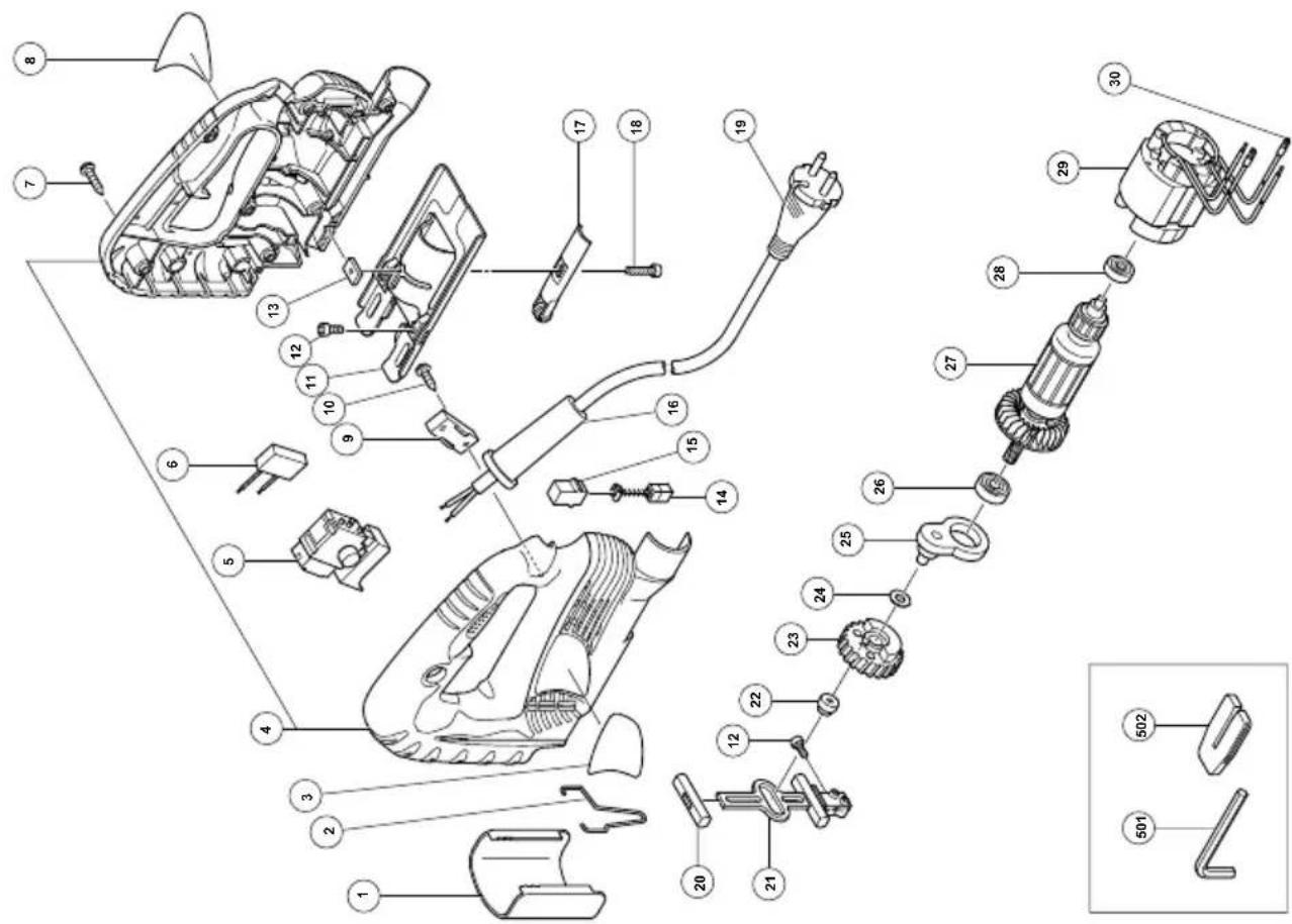
6. Service parts list
CAUTION
Repair, modification and inspection of Hitachi Power Tools must be carried out by an Hitachi Authorized Service Center.
This Parts List will be helpful if presented with the tool to the Hitachi Authorized Service Center when requesting repair or other maintenance.
In the operation and maintenance of power tools, the safety regulations and standards prescribed in each country must be observed.
MODIFICATIONS
Hitachi Power Tools are constantly being improved and modified to incorporate the latest technological advancements.
Accordingly, some parts may be changed without prior notice.
NOTE
Due to HITACHI's continuing program of research and development, the specifications herein are subject to change without prior notice.
Information concerning airborne noise and vibration
The measured values were determined according to EN60745 and declared in accordance with ISO 4871.
[CJ65V3]
Measured A-weighted sound power level: 96 dB (A). Measured A-weighted sound pressure level: 85 dB (A). Uncertainty KpA: 3 dB (A).
Wear ear protection.
The typical weighted root mean square acceleration value: 7.6 m/s ^2 .
(1) Bıçaklar, No. 1 – 6, 31*
| Item No. | Part Name |
| 1 | CHIP COVER |
| 2 | GUARD BAR |
| 3 | HITACHI LABEL |
| 4 | HOUSING (A), (B) SET |
| 5 | S W I T C H |
| 6 | NOISE SUPPRESSOR |
| 7 | TAPPING SCREW (W/FLANGE) D4×20 |
| 8 | NAME PLATE |
| 9 | CORD CLIP |
| 10 | TAPPING SCREW (W/FLANGE) D4×16 |
| 11 | BASE |
| 12 | HEX. SOCKET HD. BOLT M4×8 |
| 13 | PLATE NUT |
| 14 | CARBON BRUSH |
| 15 | BRUSH HOLDER |
| 16 | CORD ARMOR |
| 17 | ROLLER HOLDER |
| 18 | HEX. SOCKET HD. BOLT M4×16 |
| 19 | CORD |
| 20 | PLUNGER HOLDER |
| 21 | PLUNGER |
| 22 | CONNECTING PIECE |
| 23 | GEAR |
| 24 | WASHER |
| 25 | HOLDER |
| 26 | BALL BEARING 608VVMC2EPS2L |
| 27 | ARMATURE |
| 28 | BALL BEARING 626VVMC2ERPS2S |
| 29 | STATOR |
| 30 | TERMINAL |
| 501 | HEX. BAR WRENCH 3MM |
| 502 | SPLINTER GUARD |
CJ65S3
| English | Magyar | ||
| GUARANTEE CERTIFICATE1Model No.2Serial No.3Date of Purchase4Customer Name and Address5Dealer Name and Address(Please stamp dealer name and address) | GARANCIA BIZONYLAT1Tipusszám2Sorozatszám3A vásárlás dátuma4A Vásárló neve és címe5A Kereskedő neve és címe(Kérjük ide elhelyezni a Kereskedő nevének és címének pecsétjét) | ||
| Deutsch | Čeština | ||
| GARANTIESCHEIN1Modell-Nr.2Serien-Nr.3Kaufdaturn4Name und Anschrift des Kunden5Name und Anschrift des Händlers(Bitte mit Namen und Anschrift des Handlers abstempeln) | ZÁRUČNÍ LIST1Model č.2Série č.3Datum nákupu4Jméno a adresa zákazníka5Jméno a adresa prodejce(Prosíme o razítko se jménem a adresou prodejce) | ||
| Ελληνικά | Türkçe | ||
| ΠΙΣΤΟΠΟΙΗΤΙΚΟ ΕΓΓΥΗΣΗΣ1Αρ. Μοντέλου2Αύξων Αρ.3Ημερομηνία αγοράς4Όνομα και διεύθυνση πελάτη5Όνομα και διεύθυνση μεταπωλητή(Παρακαλούμε να χρησιμοποιηθεί σφραγίδα) | GARANTI SERTIĆIKASI1Model No.2Seri No.3Satın Alma Tarihi4Müşteri Adı ve Adresi5Bayi Adı ve Adresi(Lütfen bayi adını ve adresini kaşe olarak basın) | ||
| Polski Русский | |||
| GWARANCJA1Model2Numer seryjny3Data zakupu4Nazwa klienta i adres5Nazwa dealera i adres(Pieczęć punktu sprzedaży) | ГАРАНТИЙНЫЙ СЕРТИФИКАТ1Модель No2Серийный No3Дата покупки4Название и адрес заказчика5Название и адрес дилера(Пожалуйста, внесите название и адрес дилера) | ||
HITACHI
| 1 | |
| 2 | |
| 3 | |
| 4 | |
| 5 |
Hitachi Koki
natural_image
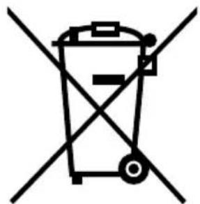
Symbol of a trash bin crossed with no text or labelsEnglish
Only for EU countries
Do not dispose of electric tools together with household waste material!
In observance of European Directive 2002/96/EC on waste electrical and electronic equipment and its implementation in accordance with national law, electric tools that have reached the end of their life must be collected separately and returned to an environmentally compatible recycling facility.
Deutsch
Nur für EU-Länder
- GENERAL SAFETY RULES
- WARNING!
- Read all instructions
- SAVE THESE INSTRUCTIONS
- 1) Work area
- 2) Electrical safety
- 3) Personal safety
- 4) Power tool use and care
- 5) Service
- PRECAUTION
- STANDARD ACCESSORIES
- OPTIONAL ACCESSORIES (sold separately)
- APPLICATIONS
- PRIOR TO OPERATION
- Power source
- Power switch
- Extension cord
- MOUNTING THE BLADE
- CAUTION
- NOTE
- CHIP COVER POSITIONING
- Chip cover
- How to choose the position of the ship cover
- ADJUSTING THE BLADE OPERATING SPEED .... (CJ65V3 only)
- CUTTING
- Rectilinear cutting
- Cutting a circle or a circular arc
- Sawing curved lines
- Cutting metallic materials
- Pocket cutting
- Angular cutting
- Dust produced in operation
- SELECTION OF BLADES
- Accessory blades
- Acceptable commercial blades (Fig. 14)
- MAINTENANCE AND INSPECTION
- Inspecting the blade
- Inspecting the mounting screws
- Maintenance of the motor
- Replacing supply cord
- Servicing
- Service parts list
- MODIFICATIONS
- Information concerning airborne noise and vibration
- [CJ65V3]
- HITACHI
- English
- Deutsch
Brand : HITACHI
Model : CJ 65S3
Category : Saw