524.60 - Range hood Zelmer - Free user manual and instructions
Find the device manual for free 524.60 Zelmer in PDF.


| Product type | Range hood |
| Brand | Zelmer |
| Model | 524.60 |
| Installation type | Wall-mounted |
| Width | 60 cm |
| Depth | 50 cm |
| Height (chimney) | Adjustable, up to 120 cm |
| Net weight | 12 kg |
| Power supply | 220-240 V ~ 50 Hz |
| Maximum power consumption | 150 W |
| Maximum extraction rate | 600 m³/h |
| Number of speeds | 3 |
| Noise level (max speed) | 60 dB |
| Lighting type | LED, 2 x 3 W |
| Grease filter type | Aluminum mesh, washable |
| Charcoal filter | Optional, replaceable |
| Control type | Electronic push buttons |
| Energy class | A |
| Exhaust diameter | 150 mm |
| Safety features | Overheat protection, automatic shut-off |
| Maintenance | Clean grease filter monthly; replace charcoal filter every 3-6 months |
| Spare parts | Grease filter, charcoal filter, LED bulbs |
| Warranty | 2 years |
Frequently Asked Questions - 524.60 Zelmer
User questions about 524.60 Zelmer
0 question about this device. Answer the ones you know or ask your own.
Ask a new question about this device
Download the instructions for your Range hood in PDF format for free! Find your manual 524.60 - Zelmer and take your electronic device back in hand. On this page are published all the documents necessary for the use of your device. 524.60 by Zelmer.
USER MANUAL 524.60 Zelmer
natural_image
Close-up of a kitchen appliance control panel with five buttons (labeled 0 to 3) and a small indicator button on the right (no text or symbols beyond labels)KONSERWACJA I CZYSZCZENIE
Konserwacja
natural_image
Hand placing a small object into a metal rack with a fan (no text or symbols visible)natural_image
Three technical line drawings of a grid-patterned architectural or architectural component, showing structural changes without any text or symbols.Oświetlenie
natural_image
Diagram showing three stages of a mechanical component with arrows indicating direction (no text or symbols)Czyszczenie
natural_image
Close-up of a kitchen appliance control panel with five buttons labeled 0 to 3 (no text or symbols beyond labels)ÚDRŽBA A ČIŠTĚNÍ
Údržba
natural_image
Hand inserting a small component into a metal kitchen appliance (no text or symbols visible)natural_image
Three technical line drawings of a grid-patterned architectural or mechanical component, showing structural changes without any text or symbols.Osvětlení
natural_image
Diagram showing three stages of a mechanical component with arrows indicating direction (no text or symbols)Čištění
Pripojenie k elektrickej sieti a kontrola fungovania
natural_image
Close-up of a kitchen appliance front panel with five white buttons labeled 0 to 3 and a small circle on the right (no text or symbols beyond numeric labels)ÚDRŽBA A ČISTENIE
Údržba
natural_image
Hand inserting a small component into a metal oven (no text or symbols visible)natural_image
Three technical line drawings of a grid-patterned architectural or architectural component, showing structural changes without any text or symbols.Osvetlenie
natural_image
Diagram showing three stages of a mechanical assembly with arrows indicating direction (no text or symbols)Čistenie
natural_image
Close-up of a kitchen appliance control panel with five buttons (labeled 0 to 3) and a small circular icon on the right side (no text or symbols beyond labels)natural_image
Hand placing a small object into a metal kitchen oven (no text or symbols visible)natural_image
Three technical line drawings of a grid-patterned architectural or mechanical component, shown from different angles (no text or symbols)Világítás
natural_image
Diagram showing three stages of a mechanical assembly with arrows indicating direction (no text or symbols)Tisztítás
natural_image
Close-up of a kitchen appliance control panel with five buttons (0 to 3) and a small indicator symbol (no text or labels visible)natural_image
Hand inserting a small component into a metal rack (no text or symbols visible)natural_image
Three technical line drawings of a grid-patterned architectural or mechanical component, showing structural deformation (no text or symbols)Sistem de iluminare
natural_image
Diagram showing three stages of a mechanical component with arrows indicating direction (no text or symbols)natural_image
Close-up of a kitchen appliance front panel with five white buttons labeled 0 to 3 and a small circle on the right (no text or symbols beyond labels)natural_image
Hand inserting a small component into a metal kitchen appliance (no visible text or symbols)natural_image
Three technical line drawings of a grid-patterned architectural or mechanical component, showing structural deformation (no text or symbols)Освещение
natural_image
Diagram showing a mechanical assembly with three stages of ring closure and directional arrows indicating motion (no text or symbols)natural_image
Close-up of a kitchen appliance front panel with five white buttons labeled 0 to 3 and a small circle on the right (no text or symbols beyond labels)natural_image
Hand inserting a small component into a metal kitchen fan (no text or symbols visible)natural_image
Three technical line drawings of a folded or layered structure, showing structural deformation (no text or symbols)Осветление
natural_image
Diagram showing three stages of a mechanical component with arrows indicating direction (no text or symbols)Почистване
natural_image
Close-up of a kitchen appliance control panel with five buttons (labeled 0 to 3) and a small indicator symbol (no readable text or numbers)natural_image
Hand inserting a small component into a metal air vent (no text or symbols visible)natural_image
Three technical line drawings of a grid-patterned architectural or architectural component, showing structural changes without any text or symbols.Освітлення
natural_image
Diagram showing three stages of a mechanical assembly with arrows indicating direction (no text or symbols)Important safety instructions....58
Technical parameters 59
Features 60
Parts 60
Assembly....60
Setting the operation mode 61
Operation....62
Cleaning and maintenance....62
Ecology – Environmental protection....63
Dear Customers
Please read these instructions carefully. Pay special attention to important safety instructions to avoid accidents and/or damage to the appliance. Keep this User's Guide for future reference.
IMPORTANT SAFETY INSTRUCTIONS
Read the entire instruction manual before operating the appliance. –
- The appliance is intended for household use only. The warranty conditions change if the appliance is used in gastronomic business.
Do not unplug by pulling on cord. –
The cord cannot touch hot surfaces. -
- Do not operate the appliance if it has a damaged cord or if the housing is visibly damaged. If the non-detachable part of the cord is damaged, it should be replaced by the producer or at a proper service point or by a qualified person in order to avoid any hazards.
The appliance can only be repaired by qualified service personnel. Improper servicing may cause a serious hazard to the user. In case of defects please contact a qualified service center.
- The cooker hood is used to extract cooking fumes to the outside. It should be connected to an appropriate ventilation duct (do not connect to working chimney ducts, smoke ducts or exhaust fume ducts).
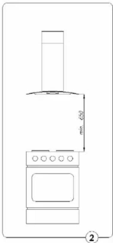
- The appliance should be installed at the height of at least 650 mm from the electric cooking plate and at least 700 mm from a gas cooker.
- Do not leave an open flame under the cooker hood. Set the minimal flame while removing pots from the gas ring.
- Dishes prepared using fats should be constantly supervised, as overheated fat may easily catch fire.
- Clean the cooker hood anti-grease filter at least every 2 months. A filter saturated with grease is flammable.
- Unplug the appliance before each cleaning operation, before replacing the filter or starting any repair works.
- If there are other appliances with non-electric supply (e.g. liquid fuel stoves, flow heaters, therms) in the room apart from the hood, a sufficient ventilation (air intake) should be provided. Safe exploitation is possible if during the simultaneous operation of the cooker hood and combustion appliances dependant on the air inside the room, the underpressure in the place where those appliances are located amounts to 0.004 milibar at the highest (this does not apply if the cooker hood is used as the odor absorber).
- Anti-grease filters as well as active-coal filters should be cleaned or replaced according to the recommendations of the manufacturer or more often, if they are intensively used (more than 4 hours a day).
- Always check if the flame does not exceed the pot, as this causes undesirable energy losses and a dangerous heat concentration. Use the cooker hood only for its intended use.
- Do not wash under running water. Do not immerse the appliance and the cord into water.
- Do not use abrasive detergents such as emulsions, cream cleaners, polishes, etc. to clean the housing. They may remove the graphic information symbols such as: scales, marks, warning signs etc.
- The use of accessories not recommended by the manufacturer may cause damage to the appliance.
- This appliance is not intended for use by persons (including children) with reduced physical, sensory or mental capabilities, or lack of experience and knowledge, unless they have been given supervision or instruction concerning use of the appliance by a person responsible for their safety.
- Children should be supervised to ensure that they do not play with the appliance.
Make sure that the above instructions have been understood.
TECHNICAL PARAMETERS
| Features | Hood type524.60, 524.90 |
| Voltage 230 V ~ 50 Hz | |
| Fan motor 1 | |
| Lighting Halogen lamps 2 | x 20 W |
| Speed settings 3 | |
| Width [cm] 60/90 | |
| Depth [cm] 50 | |
| Height [cm] | 485–915 |
| Outlet [ø mm] | 150 (120) |
| Efficiency – [m3/h] | Max 650 |
| Energy consumption [W] | 160 |
| Loudness [dBA] | Max 56 |
| Type of operation | Extraction or absorption |
| Color | INOX stainless steel |
The appliance meets the requirements of the applicable norms.
The appliance is in conformity with the requirements of the directives:
Low voltage appliance (LVD) - 2006/95/EC.
- Electromagnetic compatibility (EMC) – 2004/108/EC.
The appliance was marked by a CE sign on the rating label.
FEATURES
ZELMER cooker hood is used to extract cooking fumes. It requires to install a duct extracting air to the outside. The length of the duct (most commonly a tube ∅ 150 mm, ∅ 120 mm) should not exceed 4-5 m. After installing the active-coal filter which is available in the sales network, the cooker may operate as an odor absorber. In this case it is not required to install the duct extracting the air to the outside.
The cooker hood is a class II electrical appliance.
It is equipped with an independent lighting and an extract fan with three speed settings.
The cooker hood is designed for a permanent installation on a vertical wall above the gas or electric cooker.
PARTS
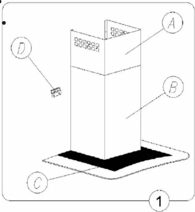
The cooker hood is composed of the following elements (fig. 1):
bent glass C together with the body, •
telescopic chimney comprising of:
upper chimney A, •
lower chimney C equipped with
the lighting and the fan unit,
wall hanger D, ●
reduction adaptor, ●
air exhaust fin.
ASSEMBLY
In order to assemble the cooker hood:
- Fix the wall hanger D at an appropriate height.
- Hang the hood body C and lower chimney B (both elements should constitute an integral part).
- Plug in the cooker hood.
- Connect the cooker hood to the ventilation duct.
- Install the telescopic chimney column A and B.
Installing the wall hanger
-
Using a level, draw a vertical line on the wall from the center of the heating plate to the ceiling. This will ensure a proper and vertical installation of the hanger on the wall.
-
Place the hanger D against the wall with its marked center on the vertical line, the distance between the holes and the heating plate should be at least 970 mm.
Note: Make sure the hanger D is leveled.
Mark the center of the hanger holes on the wall.
- Drill the holes marked on the wall using a drill with the diameter of 8mm, fix the hanger using rawlplugs and screws.
Installing the cooker hood
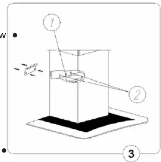
The cooker hood housing C should be hung on ● the previously installed hanger D.
Attach the cooker hood to the hanger using a screw (1) – do not tighten the screw until the end.
Level the cooker hood using the screws (2) •
Tighten the screw (1). •
The chimney is composed of two u-shaped sections with an adjustable height.
In order to fix the upper chimney A to the chimney B (which is permanently fixed to the glass C), slide both chimneys apart to the desired height.
Screw the upper chimney A tight to the lower chimney B using two screws.
Plug in and operation control
After plugging the appliance in (according to the previously described requirements), check if the cooker hood lighting works and if its motor operates correctly.
After installing the cooker hood, the socket should be easily accessible in order to unplug the appliance.
Setting the extraction operation mode
During the extraction mode, air is extracted to the outside with a special duct. Remove the coal filters with this setting.
The cooker hood is connected to an opening that extracts the air to the outside with a stiff or flexible duct with the diameter of 150 or 120 mm and appropriate duct clamps which are to be purchased in installation materials supply stores. The installation should be performed by a qualified fitter.
Setting the odor absorber operation mode
While using this mode, filtered air comes back to the room through openings on both sides of the upper chimney. While using this mode, the coal filter should be installed, it is also recommended to install an air exhaust fin.
The speed of the fan
The lowest and medium speed settings are used in normal conditions and low cooking fume intensity. The highest speed setting should be used only in case of an intense level of cooking fumes e.g. during frying or grilling.
OPERATION
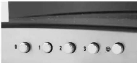
Control panel
The cooker hood can be controlled using an integrated switch.
0 - motor off,
1 – first operation speed,
2 - second operation speed,
3 – third operation speed,
- light on/off.
This adjustment allows to set the optimal fan speed for the user's needs with a minimal noise level.
natural_image
Close-up of a kitchen appliance control panel with five buttons (0 to 3) and a small indicator light (no text or symbols visible)CLEANING AND MAINTENANCE
Maintenance
Regular cleaning and maintenance will guarantee a good and failure-free operation of the cooker hood and will prolong its useful life. Make sure the aluminum filters and the active-coal filters are replaced according to the manufacturer's recommendations.
Anti-grease aluminum filters
1. Cleaning
In case of a normal operation of the cooker hood, the aluminum anti-grease filters should be cleaned every two months in a dishwasher or manually with the use of a mild detergent or liquid soap.
2. Replacement
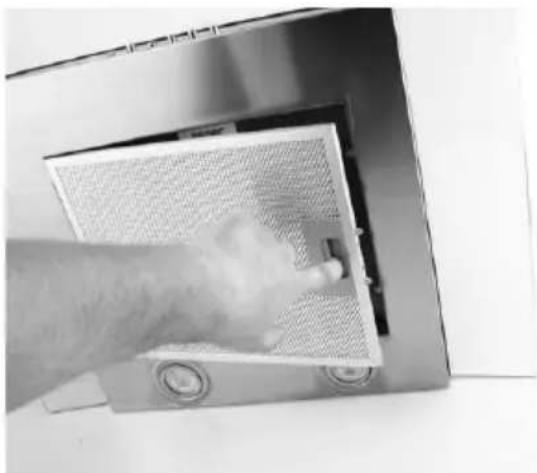
To dismantle the filters:
a) Remove the lower cover by releasing the catch.
b) Take out the aluminum anti-grease filter.
natural_image
Hand inserting a small component into a metal kitchen fan cover (no text or symbols visible)Coal filter (available at sales network)
1. Operation
Coal filters are used only when the cooker hood is not connected to the ventilation duct. Active-coal filters can absorb odors until they are saturated. Active-coal filters cannot be washed or regenerated; they should be replaced at least every two months or more often if the cooker hood is intensively used.
- Replacement
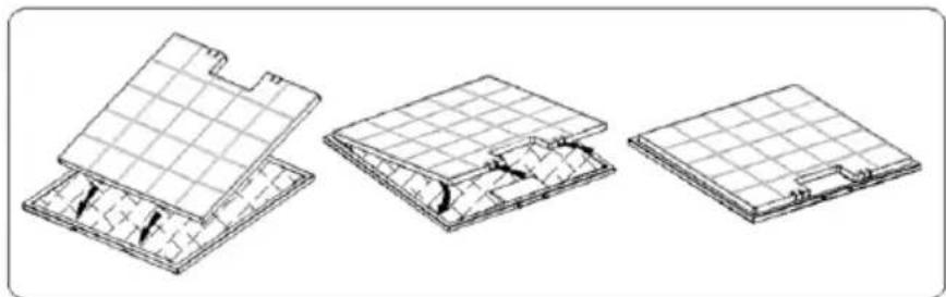
a) Remove the aluminum anti-grease filter.
b) Remove the coal filter located inside the cooker hood, on the motor housing (on both sides of the motor) by twisting it off.
c) Proceeding in the reverse order than indicated in point b, install the new filter on the motor turbine housing and turn it to protect against falling out.
natural_image
Three technical line drawings of a grid-patterned architectural or structural component, showing cross-sections and internal features (no text or symbols)Lighting
The lighting installation is composed of two 20 W halogen lamps.
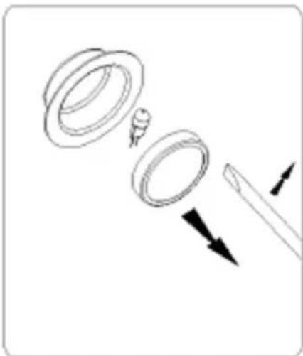
In order to replace the light bulb:
a) Unplug the cooker hood.
b) Prize up the ring around the halogen lamp with a flat tool or screwdriver and carefully remove it.
c) Replace the light bulb using a cloth or paper.
d) Reinstall the ring together with the glass proceeding in the reverse order.
NOTE: Make sure not to touch the installed halogen lamp light bulb directly with fingers!
natural_image
Diagram showing three stages of a mechanical component with arrows indicating direction (no text or symbols)Cleaning
During the normal cleaning process do not:
Use soaked cloths, sponges or running water. ●
Use solvents or alcohol, as they may tarnish the lacquered surfaces.
- Use corrosive substances, especially for cleaning stainless steel surfaces.
Use a hard, rough cloth.
It is recommended to use a damp cloth and neutral cleaning agents.
ECOLOGY - ENVIRONMENT PROTECTION
Each user can protect the natural environment. It is neither difficult nor expensive.
In order to do it: put the cardboard packing into recycling paper container; put the polyethylene (PE) bags into container for plastic.
When worn out, dispose the appliance to particular disposal centre, because of the dangerous elements of this appliance, which can be hazardous for natural environment.
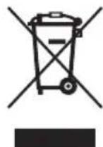
Do not dispose into the domestic waste disposal!!!
The manufacturer/importer does not accept any liability for any damages resulting from unintended use or improper handling.
The manufacturer/importer reserves his rights to modify the product any time in order to adjust it to law regulations, norms, directives, or due to construction, trade, aesthetic or other reasons, without notifying in advance.


- KONSERWACJA I CZYSZCZENIE
- Konserwacja
- Oświetlenie
- Czyszczenie
- ÚDRŽBA A ČIŠTĚNÍ
- Údržba
- Osvětlení
- Čištění
- Pripojenie k elektrickej sieti a kontrola fungovania
- ÚDRŽBA A ČISTENIE
- Osvetlenie
- Čistenie
- Világítás
- Tisztítás
- Sistem de iluminare
- Освещение
- Осветление
- Почистване
- Освітлення
- Dear Customers
- IMPORTANT SAFETY INSTRUCTIONS
- FEATURES
- PARTS
- ASSEMBLY
- In order to assemble the cooker hood:
- Installing the wall hanger
- Installing the cooker hood
- Plug in and operation control
- Setting the extraction operation mode
- Setting the odor absorber operation mode
- The speed of the fan
- OPERATION
- Control panel
- CLEANING AND MAINTENANCE
- Maintenance
- Anti-grease aluminum filters
- Cleaning
- Replacement
- Coal filter (available at sales network)
- Operation
- Lighting
- Cleaning
- ECOLOGY - ENVIRONMENT PROTECTION
Brand : Zelmer
Model : 524.60
Category : Range hood