
Vess A6800 - Security Camera Promise Technology - Free user manual and instructions
Find the device manual for free Vess A6800 Promise Technology in PDF.


| Product Type | Storage Appliance for Video Surveillance (Network Video Recorder) |
| Brand | Promise Technology |
| Model | Vess A6800 (VES0604) |
| Form Factor | 4U, 19-inch rack mount |
| Dimensions (H x W x D) | 173 x 503 x 447 mm (6.8 x 19.8 x 17.6 in) |
| Weight | Approximately 25 kg (55 lbs) without drives |
| Drive Bays | 24 hot-swappable 3.5" or 2.5" SATA/SAS drives |
| Processor | Intel Core i7-7700 |
| System Memory | 8 GB DDR4 Non-ECC (expandable to 64 GB) |
| Network | 2 x Gigabit Ethernet RJ-45 ports (1000Base-T) |
| Expansion Slots | PCIe 3.0 x16, x8, x4, x1, M.2 |
| RAID Levels | 0, 1, 1E, 3, 5, 6, 10, 30, 50, 60 |
| Maximum LUNs | 256 per system, 32 per array |
| Power Supply | 1100W (2+1@550W) redundant, hot-swappable |
| AC Input | 100~240 VAC, 50/60 Hz, 8-4A |
| Operating Temperature | 5°C to 40°C (41°F to 104°F) |
| Relative Humidity | 10% to 80% non-condensing |
| Management | Web GUI (Promise Management GUI), CLI, SNMP, USB |
| Supported OS | Windows 10 (default), Windows Server 2016 R2 |
| Event Notification | Email, SNMP, buzzer, LEDs |
| Warranty | 3 years limited hardware warranty |
| Hot-Swap Components | Drives, power supplies |
| Security | Secure cover with lock, ESD protection, FCC Class A |
| Scalability | Up to 5 JBODs for additional storage |
Frequently Asked Questions - Vess A6800 Promise Technology
User questions about Vess A6800 Promise Technology
0 question about this device. Answer the ones you know or ask your own.
Ask a new question about this device
Download the instructions for your Security Camera in PDF format for free! Find your manual Vess A6800 - Promise Technology and take your electronic device back in hand. On this page are published all the documents necessary for the use of your device. Vess A6800 by Promise Technology.
USER MANUAL Vess A6800 Promise Technology
Vess A6600 (VES0603)
Vess A6800 (VES0604)
Storage Appliance for Video Surveillance Product Manual
Version 1.0
Also included are four levels of notices:

Warning
A Warning notifies you of probable equipment damage or loss of data, or the possibility of physical injury, and how to avoid them.

Caution
A Caution informs you of possible equipment damage or loss of data and how to avoid them.

Important
An Important message calls attention to an essential step or point required to complete a task, including things often missed.

Note
A Note provides helpful information such as hints or alternative ways of doing a task.

Warning
Turn off the power and disconnect the power cord before servicing this device.

Warning
The electronic components within the Vess A6000 Series enclosure is sensitive to damage from Electro-Static Discharge (ESD). Observe appropriate precautions at all times when handling the Vess A6000 or its subassemblies.

Warning
- Use an approved power cord. If you have questions about the type of power cord to use, contact your PROMISE Technology, Inc. authorized service provider.
- If you have not been provided with a power cord for your product or for any AC-powered option intended for your product, purchase a power cord that is approved for use in your country.
- You must use a power cord rated for your product and for the voltage and current marked on the electrical ratings label of the product. The voltage and current rating of the cord must be greater than the voltage and current rating marked on the product.
- Do not pull on a cord or cable. When unplugging from the electrical outlet, grasp the cord by the plug.
- Make sure that the total ampere rating of all products plugged into an extension cord or power strip does not exceed 80 percent of the ampere ratings limit for the extension cord or power strip.
- Do not disable the power cord grounding plug. The grounding plug is an important safety feature.
- Plug the power cord into a grounded (earthed) electrical outlet that is easily accessible at all times.
- Only a qualified technician who is familiar with fix up service procedure should install and service the equipment.
- Verify that the external power source connected to your product matches the type of power source indicated on the electrical ratings label. If you are not sure of the type of power source required, consult your PROMISE Technology, Inc. authorized service provider or local power company.

為減少電擊或設備損壞的危險:
Federal Communications Commission notice
Class A equipment
This equipment has been tested and found to comply with the limits for a Class A digital device, pursuant to Part 15 of the FCC rules. These limits are designed to provide reasonable protection against harmful interference when the equipment is operated in a commercial environment. This equipment generates, uses, and can radiate radio frequency energy and, if not installed and used in accordance with the instructions, may cause harmful interference to radio communications. Operation of this equipment in a residential area is likely to cause harmful interference, in which case the user will be required to correct the interference at personal expense
Modification
This device complies with Part 15 of the FCC Rules. Operation is subject to the following two conditions: (1) this device may not cause harmful interference, and (2) this device must accept any interference received, including interference that may cause undesired operation.
This Class A digital apparatus complies with Canadian ICES-003.
Notices for New Zealand and Australia
Class A equipment
This is a Class A product. In a domestic environment this product may cause radio interference in which case the user may be required to take adequate measures.
Notices for European Union
This product is in conformity with the protection requirements of EU Council Directive 2014/30/EU on the approximation of the laws of the Member States relating to electromagnetic compatibility. PROMSIE Technology, INC. cannot accept responsibility for any failure to satisfy the protection requirements resulting from a non-recommended modification of the product, including the fitting of non-PROMISE option cards.
This product has been tested and found to comply with the limits for Class A Information Technology Equipment according to CISPR 32/European Standard EN 55032. The limits for Class A equipment were derived for commercial and industrial environments to provide reasonable protection against interference with licensed communication equipment.
This is a Class A product. In a domestic environment this product may cause radio interference in which case the user may be required to take adequate measures.
The point of contact for regulatory matters is PROMISE TECHNOLOGY EMEA, Science Park Eindhoven 5228, 5692 EG Son, The Netherlands.
Office Hours
8:30 am - 5:00 pm (The Netherlands)
| 設備名稱:磁碟陣列儲存系統型號(型式):VES0603、VES0604Equipment nameType designation (Type) | ||||||
| 單元Unit 限 | 用物質及其化學符號Restricted substances and its chemical symbols | |||||
| 鉛Lead(Pb) | 汞Mercury(Hg) | 鎘Cadmium(Cd) | 六價鉻Hexavalent chromium(Cr+6) | 多溴聯苯Polybrominated biphenyls(PBB) | 多溴二苯醚Polybrominated diphenyl ethers (PBDE) | |
| 電路板-〇 | 〇〇〇 | 〇 | ||||
| 外殼-〇〇〇 | 〇〇〇 | 〇 | ||||
| 線材〇〇〇〇〇 | 〇〇〇 | 〇 | ||||
| 電源供應器-〇〇 | 〇〇〇 | 〇 | ||||
| 電池-〇〇〇〇 | 〇〇〇 | 〇 | ||||
| 備考1.“超出0.1 wt %”及“超出0.01 wt %”係指限用物質之百分比含量超出百分比含量基準值。Note 1: “Exceeding 0.1 wt %” and “exceeding 0.01 wt %” indicate that the percentage content of the restricted substance exceeds the reference percentage value of presence condition.備考2.“〇”係指該項限用物質之百分比含量未超出百分比含量基準值。Note 2: “〇” indicates that the percentage content of the restricted substance does not exceed the percentage of reference value of presence.備考3.“-”係指該項限用物質為排除項目。Note 3: The “-” indicates that the restricted substance corresponds to the exemption. | ||||||
CONTENTS
INTRODUCTION .... 1
SPECIFICATIONS 2
HARDWARE....4
FRONT PANEL HARDWARE 4
FRONT OF VESS A6600 5
SECURE COVER 6
FRONT PANEL LEDs....7
REAR PANEL HARDWARE....9
Vess A6000 Rear Panel Components....9
Vess A6000 Rear Panel LED Indicators 11
Vess A6000 Rear Panel Connections....11
HARDWARE SETUP 12
UNPACKING 13
PACKING LIST 13
MOUNTING THE ENCLOSURE IN A RACK....14
MOUNTING ENCLOSURE IN A RACK....15
INSTALLING OR REMOVING THE SECURITY COVER....18
INSTALLING DISK DRIVES 19
NUMBER OF DRIVES REQUIRED....19
DRIVE SLOT NUMBERING 20
REMOVING THE DRIVE CARRIER....21
INSTALLING 3.5" DISK DRIVE IN THE CARRIER ....22
INSTALLING 2.5" DISK DRIVE IN THE CARRIER ....23
MANAGEMENT PATH CONNECTION 24
CONNECT THE POWER 25
POWER ON ENCLOSURE....26
FRONT PANEL LED BEHAVIOR....27
CONNECT TO ISCSI STORAGE AREA NETWORK (SAN) 28
PROMISE MANAGEMENT GUI....29
LOGGING INTO PROMISE MANAGEMENT GUI....29
LOGGING IN AT THE ENCLOSURE....29
LOGGING IN OVER THE NETWORK 30
LOGIN SCREEN 32
USING THE PROMISE MANAGEMENT GUI INTERFACE 33
USING THE HEADER....34
USING TREE VIEW....34
USING MANAGEMENT VIEW 35
CHOOSING A DISPLAY LANGUAGE....35
VIEWING THE EVENT FRAME....36
LOGGING OUT OF PROMISE MANAGEMENT GUI 37
SUBSYSTEM MANAGEMENT....38
BACKGROUND ACTIVITIES 39
VIEW CURRENT BACKGROUND ACTIVITIES....39
VIEW BACKGROUND ACTIVITIES PARAMETERS SETTINGS 39
MANAGE BACKGROUND ACTIVITIES SETTINGS ....40
REBUILD SETTINGS....41
ADD OR DELETE AN ACTIVITY SCHEDULE....46
VIEW OR MODIFY AN EXISTING ACTIVITY SCHEDULE....46
EVENT LOGS 47
ADMINISTRATIVE TOOLS 48
RESTORE FACTORY DEFAULT SETTINGS....48
CLEAR STATISTICS....48
USER MANAGEMENT 49
VIEWING USER INFORMATION....49
MAKING USER SETTINGS 49
MAKING YOUR OWN USER SETTINGS....50
CHANGING YOUR OWN PASSWORD 50
CREATING A USER....51
LIST OF USER PRIVILEGES....52
DELETING A USER 52
VIEW NETWORK SETTINGS....53
SOFTWARE MANAGEMENT ....53
IMPORTING A CONFIGURATION SCRIPT 54
EXPORTING A CONFIGURATION SCRIPT 55
SAVING A SERVICE REPORT 56
EMAIL SERVICE....58
STOP EMAIL SERVICE 58
RESTARTING EMAIL SERVICE 58
EMAIL SETTINGS 59
SENDING A TEST EMAIL MESSAGE 59
PERFORMANCE MONITORING....60
CONTROLLERS 62
VIEW CONTROLLER INFORMATION 62
VIEWING CONTROLLER STATISTICS 64
CONTROLLER SETTINGS....65
ENCLOSURES 66
RUNNING SPARE CHECK....73
LOGICAL DRIVE SUMMARY 74
MAINTENANCE 75
REPLACING A POWER SUPPLY 76
REMOVING THE POWER SUPPLY UNIT 76
TROUBLESHOOTING....77
How do I know when a drive is failing? 78
CHECK DRIVE STATUS LEDs....78
CHECK DRIVE STATUS IN MANAGEMENT GUI....80
ANTICIPATING HARD DRIVE PROBLEMS....81
REBUILDING A DISK ARRAY 83
HOW TO REBUILD A DISK ARRAY 84
HOW TO SAVE A SERVICE REPORT....86
THE ALARM BUZZER IS SOUNDING, WHAT DOES THIS MEAN? 88
HOW TO DISABLE THE ALARM BUZZER 89
FAQ....90
APPENDIX: DRIVER INSTALLATION AND UPDATE....91
UPDATE/INSTALLATION REQUIREMENTS....91
USB FLASH DRIVE 91
UPDATE/INSTALL THE DRIVER 91
INTRODUCTION
The Vess A6000 Series Storage Appliance for Video Surveillance is specially engineered for medium to large scale IP video surveillance deployment. The Vess A6000 Series is ideally suited for continuous surveillance in banks, malls, casinos, factories, warehouses, and similarly sized commercial, residential, governmental or private enterprises. The subsystems are capable of continuous recording and playback operation without dropping frames for networked installations of 64 to 150 High-Definition IP cameras.
Vess A6000 Series Storage Appliance for Video Surveillance are available with the Windows operating system, a Video Management Software suite, and disk drives in order to streamline the installation and integration process. The Vess A6000 Series subsystems are stand-alone devices with internal RAID storage, eliminating need for additional servers, controllers, separate enclosures etc. The Vess A6000 Series uses a thoroughly tested and proven RAID engine for maximum reliability, all drive bays are hot-swappable, and models are available with redundant power supplies to ensure data safety and uninterrupted operation.
The Vess A6000 models include PCIe slots for added flexibility. The PCIe slots are suitable for video graphics cards, video encode/decode cards, RAID cards, or other useful functions available on the PCIe platform.
Storage capacity can be scaled up by adding JBODs. Up to five JBODs can be added.
SPECIFICATIONS
| Model | Vess A6600 Vess A6800 | |
| General | ||
| Form Factor 3U, 19" rack mount 4U, 19" rack mount | ||
| Function Storage Appliance for Video Surveillance | ||
| Drives | Sixteen Hot-swappable drives3.5" HDD (12Gbs SAS / 6Gbs SATA)2.5" SSD | Twenty-four Hot-swappable drives3.5" HDD (12Gbs SAS / 6Gbs SATA)2.5" SSD |
| Controller Single | ||
| Network Two Gigabit Ethernet RJ-45 ports (1000Base-T) | ||
| System Processor | VA6600: Intel® CoreTM i3-7101E / Intel Xeon E3-1275v5VA6800: Intel® CoreTM i7-7700 | |
| System Memory | Default 8GB (Maximum 64 GB) @ DDR4 Non-ECC | |
| Internal Built-in Storage 128GB M.2 | ||
| Number of HDD Supported | SAS and iSCSI with 5 JBODs(144 through SAS 4U24 JBOD per system in terms of 4U24 Head) | |
| USB Ports Front: two USB 2.0 / Rear: four USB 2.0, two USB 3.0 | ||
| Expansion Slot | PCIe 3.0 x 16PCIe 3.0 x 8PCIe 3.0 x 4PCIe 3.0 x 1M.2 | - 1 slot (PCIE4/6: x0/x16, x8/x8)- 1 slot (PCIE4: x8/x0)- 1 slot (PCIE7: shared with M.2)- 1 slot (PCIE5)- 1 slot |
| I/O Port PS/2 x 1 D-Sub DVI Port x 1 HDMI Port x 1 | ||
| Audio 5 + 1 jack | ||
| RAID | ||
| RAID Levels Supported 0, | 1, 1E, 3, 5, 6, 10 (0+1), 30, 50, 60 | |
| Hot Spares Multiple global or dedicated hot-spare drives with revertible option | ||
| Maximum LUNs per System/Array | 256/32 | |
| Software | ||
| Supported OS (64-bit) W | Windows 10 in default. Windows Server 2016R2 | |
| Management | Graphical UI/SNMP via Ethernet, CLI via Ethernet, OPAS Service via USB, SDK or API for Integration | |
| Event Notification E | mail, SNMP, Buzzer, LEDs | |
| System | ||
| AC Input 100 ~ 240 VAC, 60 ~ 50Hz | ||
| Current (Maximum) 8-4A (550W, 8A/100V, 4A/240V) | ||
| Power Supply | 550W (1+1@550W) in default.1100W (2+1@550W) optional | 1100W (2+1@550W) in default. |
| Fan Non-swappable | ||
| Temperature 5° ~ 40°C (-40° ~ 60°C non-operational) | ||
| Relative Humidity | Operational: 10% to 80% (Non-Condensing)Non-Operational: 10% to 95% (Non-Condensing) | |
| Dimensions (H x W x D) | 131 x 503 x 447 mm(5.1 x 19.8 x 17.6 in) | 173 x 503 x 447 mm(6.8 x 19.8 x 17.6 in) |
| Safety/EMI CE, FCC, VCCI, RCM, BSMI, KC, (EMI Class A), CB3, cTUVus4 | ||
| Warranty 3 years limited warranty | ||
HARDWARE
The following section provides a summary of the front and back panel hardware features of Vess A6600, and Vess A6800 Storage Appliance for Video Surveillance. These enclosures are referred to collectively as Vess A6000 enclosures, Vess A6000 units or Vess A6000 subsystems throughout this document when the content applies to all models in the Promise Vess A6000 Series.
FRONT PANEL HARDWARE
The front panel of Vess A6000 enclosures provide access to drives carriers. Vess A6000 units are shipped with secure covers to protect the drive carriers from being unintentionally removed.
For all Vess A6000 enclosures, defective drives can be replaced without interruption of data availability to the host computer. If so configured, a hot spare drive will automatically replace a failed drive, securing the fault-tolerant integrity of the logical drive. The self-contained hardware-based RAID logical drive in the Vess A6000 provides maximum performance in a compact external enclosure.
FRONT OF VESS A6600
The Vess A6600 enclosure features handles on each side used to secure the enclosure to an equipment rack. The system power button and two USB ports are located on the left side, and most of the front LED indicators are located on the right side.


natural_image
Front view of a Vess A6800 server rack with multiple drive bays and indicator lights (no text or symbols on the rack itself)SECURE COVER
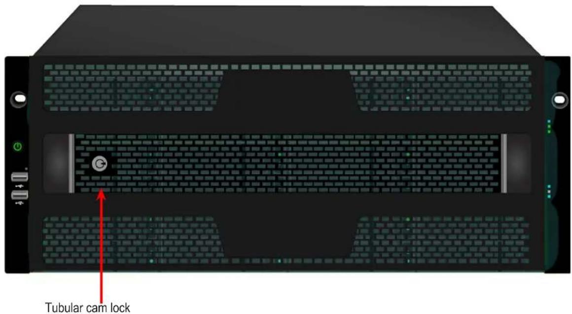
The Vess A6600/A6800/A6600/A6800 include secure covers to for better physical security and to help prevent unintended or accidental removal of hard drives. The cover are secured with a single tubular cam lock located near the left side of the cover. Turn the key clockwise to lock, counter clockwise to unlock.
Vess A6600 with secure cover (unlocked)

Vess A6800 with secure cover (locked)
FRONT PANEL LEDs
Descriptions of the LED behavior and function for Vess A6000 enclosures.
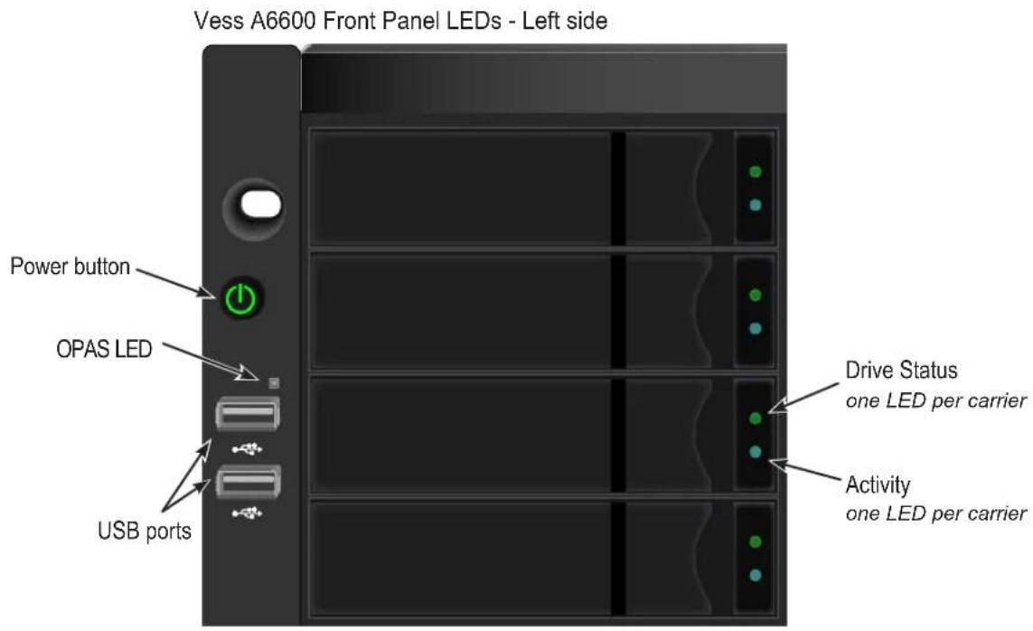
Left side LED behavior for the Vess A6000
| LED | Description |
| OPAS USB | Lights GREEN if an OPAS device (USB disk) is detected, RED if the OPAS operation has failed, blinks GREEN when an OPAS operation is in progress. |
| Drive Carrier LEDs (located on all drive carriers) | |
| Drive Status | Each drive carrier has two LEDs on the right side of the front, the Drive Status LED located above the Activity LED. The Drive Status LED displays GREEN when a drive is configured and working properly. When the lights are RED the HDD requires manual replacement. ORANGE indicates background RAID activity on this particular HDD, no user action is required. |
| Drive Activity | Steady BLUE when HDD link is established, flashes BLUE during drive activity. |
Vess A6600 Front Panel LEDs - Right side

Right side LED behavior for the Vess A6000.
| LED | Description |
| Power | Lights BLUE to indicate the system is powered on. Blinks BLUE in shutdown mode. |
| System Status | Lights GREEN when healthy, RED if there is a critical problem (LD offline, fan malfunction, voltage out of range, system temperature alert), blinks RED for HDD high temperature alert remains dark when not ready. |
| Global RAID Status | Lights GREEN when healthy or RED if any RAID volume is offline, ORANGE for critical state of any logical drive. |
| Global HDD Activity | Blinks BLUE to indicate one or more drives are being accessed, remains dark when no drives are being accessed. |
| System Heartbeat | Flashes BLUE slowly at regular intervals to indicate the firmware and software are operating normally. |
REAR PANEL HARDWARE
The rear panel of the Vess A6000 enclosures provide access to the hot-swappable power supplies, local management connection (via USB keyboard and VGA or HDMI monitor port), iSCSI (Ethernet) data ports, some units also provide I/O connections for audio sensor and alarm systems. The back panel includes two system fans.
Vess A6000 Rear Panel Components
The Vess A6600 enclosure features two hot-swappable power supplies (PSU). The Vess A6800 enclosure has three hot-swappable power supplies.
Vess A66000/A6800 rear panel components
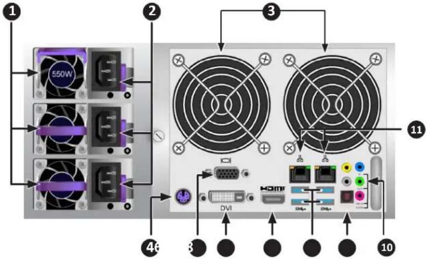
| 1 | PSU fan vents |
| 2 | Power inserts |
| 3 | System fan vents |
| 4 | PS/2 mouse/keyboard port |
| 5 | VGA port |
| 6 | DVI port |
| 7 | HDMI port |
| 8 | USB 3.0 ports (4 ports) |
| 9 | Optical SPDIF Out port |
| 10 | Audio In/Out ports |
| 11 | LAN RJ-45 ports (LAN1/LAN2) |
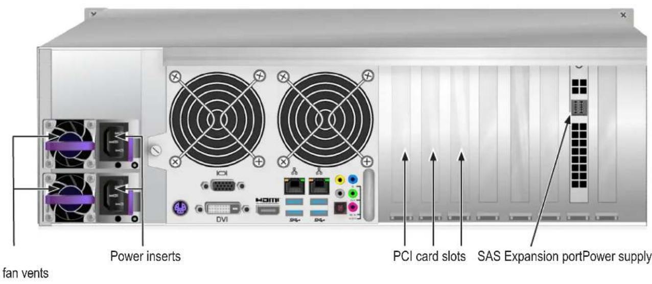
The rear panel of the Vess A6800 is nearly identical to the Vess A6600, except it is taller and has three power supplies. The form factor of the Vess A6800 is 4U, the Vess A6600 form factor is 3U.
Vess A6800 rear view

Vess A6600 rear view
Vess A6000 Rear Panel LED INDICATORS
The LEDs on the rear panel include LEDs for Ethernet data ports and an LED for each of the hot-swappable PSUs.
| LED | Description |
| Ethernet Link/Act and Speed | The LED located above each port, on the left side, lights ORANGE when connected, flashes ORANGE when there is activity on the port and remains dark no connection has been established. The LED above and on the right of each port indicates connection speed, ORANGE is 100 Mbps, GREEN is 1000 Mbps, dark is 10 Mbps. |
| PSU | Each power supply LED lights GREEN to indicate normal operation. A RED LED indicates a problem or unit failure. |
Vess A6000 Rear Panel Connections
Access to physical data and management connections are located on the back panel of the Vess A6000 including the optional I/O connections for sensor and alarm systems.
| Feature | Description |
| D-sub VGA | This is also used for a video out connection for VGA monitors, it is also used to view the management interface. |
| Display Port | This is also used for a video out connection for Display Port monitors, it is also used to view the management interface. |
| DVI | This is also used for a video out connection for DVI monitors, it is also used to view the management interface. |
| HDMI | Provides video out connection for HDMI enabled monitors used to view the management interface. |
| USB | Use to connect to a USB keyboard for managing the Vess A6000 Series, or use it to transfer data to or from a USB memory device. There are four USB 2.0 ports and two USB 3.0 ports. |
| Audio In | Use for input from a peripheral audio device, such as a microphone.Plug-In Power microphones are supported. |
| Audio Out | Use for output (line out) peripheral audio device (speakers, for example). |
| Audio Mic | Use for microphone. |
HARDWARE SETUP
This chapter presents the basics on unpacking, setting up hardware for the Vess A6000. Hardware installation includes installing the unit in an equipment rack, connecting the power, making network, data and management connection to the device, and installing hard drives.
The sections in Hardware Setup include the following:
- "Unpacking"
• "Mounting the Vess A6000 in a rack"
• "Installing Disk Drives"
• "Number of Drives Required"
• "Installing or removing the security cover"
- "Drive Slot Numbering"
• "Vess A6000 drive carriers"
• "Management Path Connection"
- "Connect the Power"
• "Power On Enclosure"
UNPACKING

Note
The Vess A6000 Series can accommodate SATA (6Gbps) or SAS (12Gbps/6Gbps) hard drives.
PACKING LIST
The Vess A6000 box contains the following items:
• One of the following storage appliances:
• Vess A6600 16-bay
• Vess A6800 24-bay
- Screws for disk drives
• Three 1.5m (4.9 ft) power cords
• Sliding rail assembly for rack mounting (optional)
• Front panel bezel cover
MOUNTING THE ENCLOSURE IN A RACK
The instructions here apply to 3U 16-bay Vess A6600, as well as the 4U 24-bay Vess A6800. The sliding rail rack mounting hardware is the same for both form factors.
Cautions

- Do not populate any unit with hard drives until it has been securely installed in the rack.
- At least two persons are required to safely lift, place, and attach the Vess A6000 unit into a rack system.
- Do not lift or move the Vess A6000 unit by the handles, power supplies or the controller units. Hold the system itself.
- Do not install the Vess A6000 unit into a rack without rails to support the system.
- Only a qualified technician who is familiar with the installation procedure should mount and install the Vess A6000 unit.
- Mount the rails to the rack using the appropriate screws and flange nuts, fully tightened, at each end of the rail.
- Do not load the rails unless they are installed with screws as instructed.
- The rails available for the Promise Vess A6000 unit are designed to safely support that Promise Vess A6000 unit when properly installed. Additional loading on the rails is at the customer's risk.
- Promise Technology, Inc. cannot guarantee that the mounting rails will support your Promise Vess A6000 unit unless you install them as instructed.

Note
To lighten the Vess A6000 enclosure, you can remove the power supplies. Replace the power supplies after the Vess A6000 unit is mounted in your rack.
MOUNTING ENCLOSURE IN A RACK

Note
Please refer to the Quick Installation Guide included with the mounting rails for more detailed rack installation instructions.
To install the Vess A6000 into a rack with the supplied mounting rails:
- Check the fit of the mounting rails in your rack system.
- Adjust the length of the mounting rails as needed.
• The rear rail slides inside the front rail. The rail halves are riveted together and use no adjustment screws.
• The front-left and front-right mounting rail ends are labeled.
- Be sure the front rail support is on the bottom facing inward
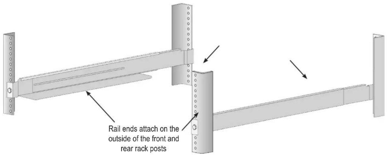
• All rail ends, front and rear, attach at the outside of the rack posts.
• The guide pins at the rail ends align with the holes in the rack posts.
- Use the attaching screws and flange nuts from your rack system. Tighten the screws and nuts according to instructions for your rack system.
Installing the rails onto the rack
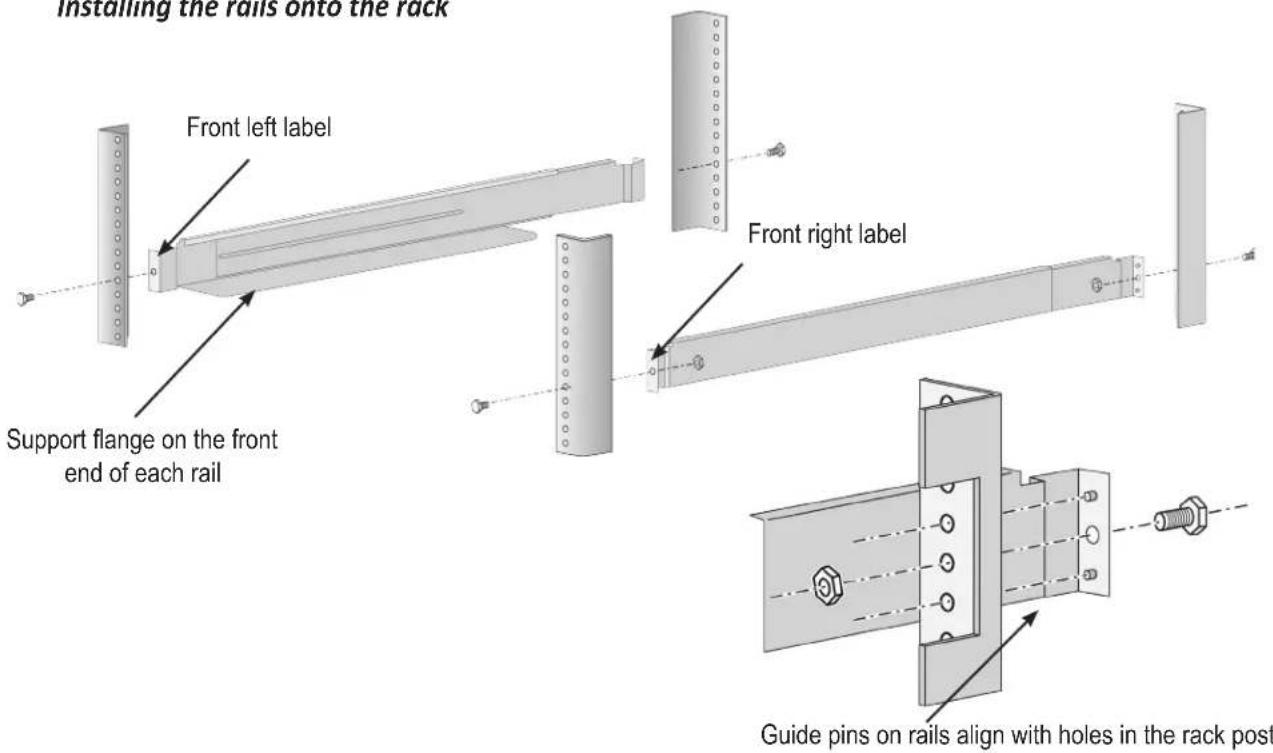
Rail ends attach to the outside of each post
-
Place the Vess A6000 onto the rails.
-
At least two persons are required to safely lift the system.
- Lift the Vess A6000 itself. Do not lift the system by its brackets.
Placing the system onto the rack rails

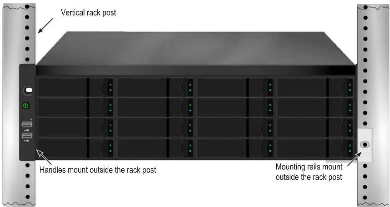
- Secure the enclosure to the rack.
- The unit attaches to the rack posts using the included screws and flange nuts. One screw each side, in the upper hole only.
• Use the attaching screws and flange nuts that came with the Vess A6000.
Secure to rack

System installed in rack
INSTALLING OR REMOVING THE SECURITY COVER
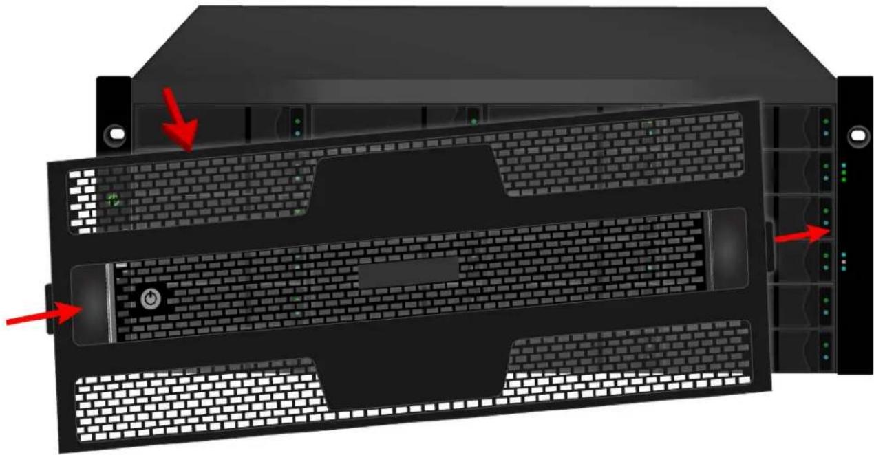
The secure cover hardware is operated in the same fashion on the Vess A6000 models.
To attach the secure cover:
- Make sure the lock is in the unlocked position. To unlock, insert the key into the lock and turn counter clockwise.
- Insert the tab on the right side of the cover into the slot receptacle on the right handle.
- Place the cover in position and push in the latch release (to the left of the keyhole).
- Push the cover into position so that the tab on the right side inserts into the receptacle on the right handle when releasing the latch.
- Insert the key and turn clockwise to lock.
To remove the cover, unlock it, press the latch release on the left side and pull the left end out first, holding it with both hands.
Vess A6800 installing and removing secure cover
natural_image
Front view of a server rack with multiple drive bays and indicator lights, showing no visible text or symbols.INSTALLING DISK DRIVES
The Vess A6000 subsystems support:
• SATA / SAS hard disks
• 3.5-inch hard disk drives
• SAS 2.5-inch hard disk drives (Optional)
NUMBER OF DRIVES REQUIRED
The table below shows the number of drives required for each RAID level
| Level | Number of Drives | Level | Number of Drives |
| RAID 0 | 1 or more | RAID 64 to 32 | |
| RAID 1 | 2 only | RAID 104 or more* | |
| RAID 1E | 2 or more | RAID 506 or more | |
| RAID 5 | 3 to 32 | RAID 608 or more |
*Must be an even number of drives.

Caution
The Vess A6000 supports disk drive hot-swapping. To avoid hand contact with an electrical hazard, do not remove more than one drive carrier a time.
DRIVE SLOT NUMBERING
You can install any suitable disk drive into any slot in the enclosure. The diagram below shows how drive slots are numbered on the Vess A6600.
Slot numbering is reflected in the web management user interfaces.
Drive slot numbering for Vess A6600

natural_image
Front view of a rack-mounted server unit with 16 numbered racks (no visible text or symbols)Drive slot numbering for Vess A6800
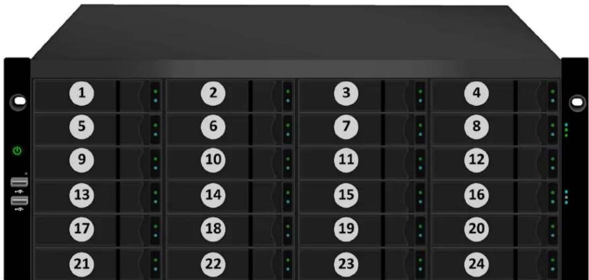
Install all of the drive carriers into the enclosure to ensure proper airflow, even if you do not populate all the carriers with disk drives.
REMOVING THE DRIVE CARRIER
The drive carrier accommodates 2.5-inch and 3.5-inch drives.
Vess A6600/A6800 Disk carrier with HDD installed - front view
Push here when returning or replacing the carrier into an empty drive bay.
Pull here to release the carrier handle latch. Then pull the carrier straight out by the handle. Place your free hand under the carrier. Do not drop the disk carrier, even if it is empty.

Tabs for locking mechanism insert. This piece must be removed to unlatch the carrier. To remove, squeeze the tabs together and pull out. To reinsert, squeeze the tabs together and replace in position. Do not discard the locking mechanisms.

Cautions
Swing open the drive carrier handle before you insert the drive carrier into the enclosure.
To avoid hand contact with an electrical hazard, remove only one drive carrier a time.
INSTALLING 3.5" DISK DRIVE IN THE CARRIER
The instructions below apply 3.5" hard disk drives installed in drive carriers intended for use with models Vess A6600 and Vess A6800.
- Remove a disk drive carrier.
- Carefully lay the disk drive into the drive carrier at the front, so that the screw holes on the sides line up correctly with the power and data connectors facing away from the carrier handle.
- Insert the screws through the holes in the drive carrier and into the sides of the disk drive.
Install only the counter-sink screws supplied with the drive.
• Install four screws per drive.
- Snug each screw. Be careful not to over-tighten.
4. Reinstall the drive carrier into the enclosure.
Repeat steps 1 through 3 until all of your disk drives are installed.
INSTALLING 2.5" DISK DRIVE IN THE CARRIER
The instructions below apply 2.5" hard disk drives installed in drive carriers intended for use with models Vess A6600 and Vess A6800.
- Remove a disk drive carrier.
- Carefully lay the disk drive into the drive carrier at the front, so that the screw holes on the bottom of the carrier line up correctly with the power and data connectors facing away from the carrier handle.
- Insert the screws through the holes on the bottom of the drive carrier and into the bottom of the disk drive.
Install only the counter-sink screws supplied with the drive.
• Install four screws per drive.
- Snug each screw. Be careful not to over-tighten.
4. Reinstall the drive carrier into the enclosure.
Repeat steps 1 through 3 until all of your disk drives are installed.
MANAGEMENT PATH CONNECTION
This section describes how to establish a management connection the Vess A6000 subsystems. Management through the Gigabit network connection is done using Promise Management GUI, a web browser based GUI.
NETWORK CONNECTION
Vess A6000 have two Gigabit Ethernet RJ-45 ports on the rear panel for connection to an Ethernet network. Use this connection with Promise Management GUI to login as the device administrator.
To establish the management path:
- Attach one end of an Ethernet cable to the network connector or standard NIC in the Host PC.
Attach the other end of the Ethernet cable to one of the ports on the standard network switch. - Attach one end of an Ethernet cable to one of the ports on the standard network switch.
Attach the other end of the Ethernet cable to either 1GbE network port on the Vess A6000 system.
(See illustration below for port location)
If you have multiple Vess A6000 systems, Host PCs or Servers, repeat steps 1 and 2 as required.
- Follow the instructions for managing the basic settings of the Vess A6000.
CONNECT THE POWER
Insert one power cable into the power receptacle for each power supply and connect the each PSU to a suitable power source. The subsystem is equipped with three power supplies in an N+1 arrangement.
Each PSU has a Status LED. After boot up, check the LEDs on each power supply on the back of the device. These LEDs will light green to indicate normal operation. A red LED indicates a problem or unit failure.

Important
The Vess A6800 features three N+1 power supplies. In this arrangement, one PSU is redundant, so a minimum of two PSUs are needed to power up the enclosure.
The Vess A6600 feature two N+1 power supplies. In this arrangement, one PSU is redundant, so a minimum of one PSU is needed to power up the enclosure.
Vess A6800 N+1 power connections

Connect all power supplies to a suitable power source.

Warning
Turn off the power and disconnect all power cord before servicing the Vess A6600 and Vess A6800.
POWER ON ENCLOSURE
With the power supplies connected, the system can now be powered on.
If you are using JBOD storage expansion setup, power on the JBODs first.
To power on the Vess A6000 subsystem, press the Power button on the front left bracket facing (see figure below). Observe the LEDs on the front panel to make certain the boot up proceeds smoothly.
Vess A6600 front panel components, left side

Vess A6600 front right side

FRONT PANEL LED BEHAVIOR
The table below describes LED behavior when boot-up is finished and the system is functioning normally:
| LEDDescription | |
| Power | Lights BLUE to indicate the system is powered on. |
| System Status | Lights GREEN when healthy, RED if there is a critical problem (LD offline, fan malfunction, voltage out of range, system temperature alert), blinks RED for HDD high temperature alert remains dark when not ready. |
| Global RAID Status | Lights GREEN when healthy or RED if any RAID volume is offline, ORANGE for critical state of any logical drive, or when the system is rebuilding. |
| Global HDD Activity | Blinks BLUE to indicate one or more drives are being accessed, lights steady BLUE when no drives are being accessed. |
| System Heartbeat | Blinks BLUE slowly at regular intervals to indicate the firmware and software are operating normally. |
| OPAS USB | Lights GREEN if an OPAS device (USB disk) is detected, remains dark if the OPAS operation has failed, blinks GREEN when an OPAS operation is in progress. |
CONNECT TO ISCSI STORAGE AREA NETWORK (SAN)

Important
For a list of supported HBA NICs and switches, download the latest compatibility list from PROMISE support: http://www.promise.com/support/.
This arrangement requires:
• An iSCSI HBA network interface card (NIC) in the host PC or server
• A GbE network switch
• A standard network switch

Note
Only one iSCSI data cable is required between each Vess enclosure and the GbE network switch. However, you can attach multiple cables to create redundant data paths.
Gigabit Ethernet Network ports on rear panel

PROMISE MANAGEMENT GUI
This chapter describes using Promise Management GUI to monitor and manage your RAID system.
LOGGING INTO PROMISE MANAGEMENT GUI
You can log into Promise Management GUI in either of two ways:
• "Logging in at the Enclosure" on page 29
• "Logging in over the Network" on page 30
LOGGING IN AT THE ENCLOSURE
At the Vess A6000 enclosure to log into Promise Management GUI, do one of the following actions:
• Double-click the Promise Management GUI desktop icon.
- Choose Promise Management GUI in the Windows Programs menu.
- Follow the steps under "Logging in over the Network" on page 30.

Note
The default IP settings for the Gigabit Ethernet ports are:
Port 1 = 192.168.0.1
Port 2 = 192.168.1.1
IP settings for the ports are controlled by the OS. Use the normal IP settings configuration procedure for the OS you are using if you want to change the default settings.
LOGGING IN OVER THE NETWORK

Important
For Vess A6000 Series running Windows OS, it is necessary to disable the Windows Firewall in order to allow access to Promise Management GUI through the network interface. If the Firewall is running, no management access is permitted from the network.
You can log into Promise Management GUI from any PC with a network connection to the and Vess A6000 Series enclosure.
- Launch your Browser.
- In the Browser address field, type the information provided below. Then press Enter. Note that this example uses the default IP address for Port 1
If you chose External SSL Security during installation, use the Secure Connection. Otherwise, use the Regular Connection.
Regular Connection
- Promise Management GUI uses an HTTP connection. . . . . . . . . . . . . . . . . . . . . . . . . . . . . . . . . . . . . . . . . . . . . . . . . . . . . . . . . . . . . . . . . . . . . . . . . . . . . . . . . . . .
- Enter the Subsystem IP address ..... 192.168.0.1
- Enter the Port number .....:8090
Together, your entry looks like this:
http://192.168.0.1:8090
Secure Connection
- Promise Management GUI uses a secure HTTP connection . . . . . . . . . . . . . . . . . . . . . . . . . . . . . . . . . . . . . . . . . . . . . . . . . . . . . . . . . . . . . . . . . . . . . . . . . . . . . . .
- Enter the Subsystem IP address ..... (Port 1 = 192.168.0.1 / Port 2 = 192.168.1.1)
• Enter the Port number .....:443
Together, your entry looks like this:
https://192.168.0.1:443/

natural_image
Simple icon of a yellow pencil inside a square frame (no text or symbols)Note
- You can enter the Host PC's network name in place of the IP address.
- If you are logging in at the Host PC, you can enter local Host in place of the IP address.
- Whether you select a regular or a secure connection, your login to Promise Management GUI and your user password are always secure.
LOGIN SCREEN
When the opening screen appears:
- Type administrator in the User Name field.
- Type password in the Password field.
- Click the Login button.
The User Name and Password are case sensitive.
The Promise Management GUI login screen

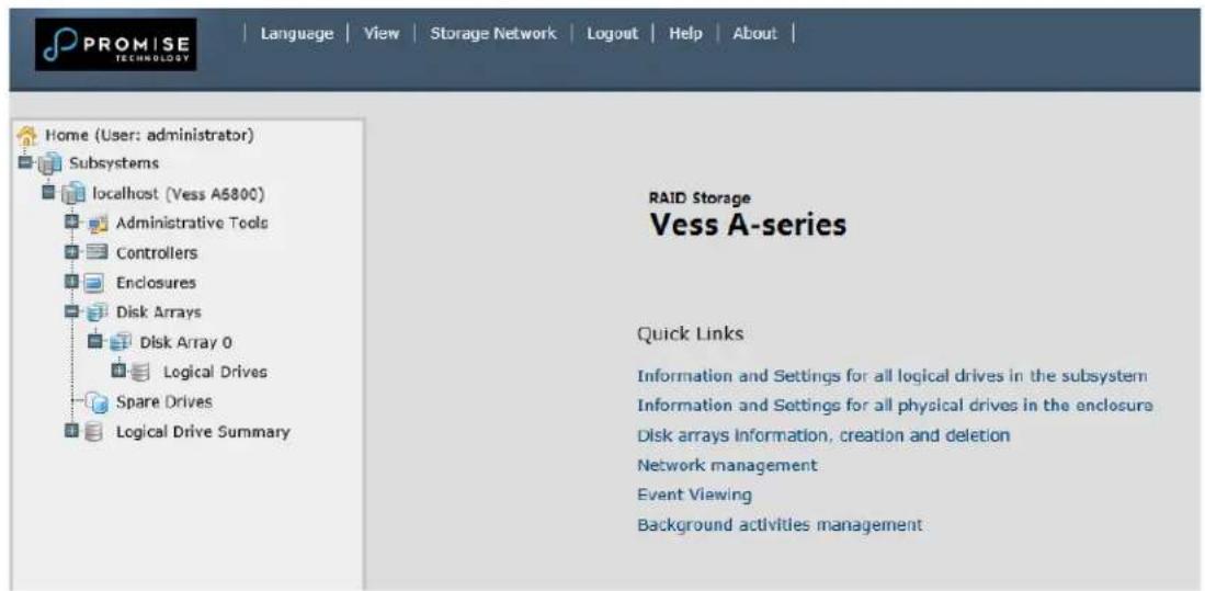
After logging in, the Quick Links menu appears.
Quick Links menu
USING THE PROMISE MANAGEMENT GUI INTERFACE
Promise Management GUI is browser-based RAID management software with a graphic user interface. Basic user interface components and functions include:
Promise Management GUI interface - Subsystem home page
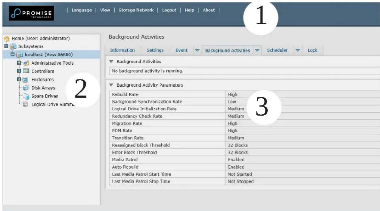
There are three parts to the Promise Management GUI interface:
- Header
- Tree View
- Event Frame
USING THE HEADER
The Header contains the following items:
Language – Choose a display language
View – To view the Event Frame,
Logout – To logout
USING TREE VIEW
Tree View enables you to navigate around all components of the Vess A6000 enclosure, software management, RAID controller, enclosure, physical drives, disk arrays, logical drives, and spare drives. The figure below shows the components of Tree View.
Promise Management GUI Tree View

The Administrative Tools section is different for the Administrator and Super Users than for other users. The remainder of the Tree is the same for all users.
USING MANAGEMENT VIEW
Management View displays information and settings menus according to the item you choose in Tree View. It presents the user interface for the Vess A6000 enclosure, including creation, maintenance, deletion, and monitoring of disk arrays and logical drives. Function tabs access menus to control specific actions and processes.
Click the Help link to the right of the tabs in Management View to access online help for the function currently displayed.
CHOOSING A DISPLAY LANGUAGE
Promise Management GUI displays in the following languages:
- English
- Simplified Chinese
- Traditional Chinese
- Japanese
- Korean
- Arabic
-
Polish
-
French
- German
- Italian
- Spanish
- Portuguese
- Turkish
- Russian
To change the display language:
- Click the Language drop-down menu in the Header.
- Highlight the language you prefer.
Promise Management GUI displays in the chosen language.
VIEWING THE EVENT FRAME
To view the Event Frame, click Show Event Frame in the Header. To hide the Event Frame, click Hide Event Frame in the Header.
In the event frame, events are listed and sorted by:
• Device – Disk array, logical drive, physical drive, controller, etc.
• Event ID – The hexadecimal number that identifies the specific type of event
• Severity – See below:
• Information – Information only, no action is required
- Warning – User can decide whether or not action is required
- Minor – Action is needed but the condition is not serious at this time
• Major – Action is needed now
• Critical – Action is needed now and the implications of the condition are serious
- Fatal – Non-Recoverable error or failure has occurred
• Time – Time and date of the occurrence
• Description – A brief description of the event
You can also view events by clicking the Subsystems icon in Tree View, then clicking the Event tab in Management View.
LOGGING OUT OF PROMISE MANAGEMENT GUI
There are two ways to log out of Promise Management GUI:
- Close your browser window
- Click Logout in the Promise Management GUI Header
Clicking Logout brings you back to the Login Screen. After logging out, you must enter your user name and password in order to log in again.
SUBSYSTEM MANAGEMENT
The menus listed under Subsystems are all the menus used for device management. Click on the Subsystems icon to view read-only information for the Vess A6000 including the management IP address, Alias, Model and WWN.
To view the menus used for system management, click the + symbol of the Subsystems icon to reveal the child menu icons for the following:
- Administrative Tools (includes links for User Management, View Network Settings, Performance Monitoring and Software Management)
- Controllers (view controller information and manage settings)
- Enclosures (view device information and virtual enclosure, set temperature thresholds for warnings and enable/disable warning buzzer)
• Disk Arrays (manage disk arrays) - Spare Drives (manage spare drives)
• Logical Drives Summary (read-only logical drive information display)
Click on the subsystem IP address and model name listed under the Subsystems top-level menu icon in Tree View. In the Information tab, the following information for the subsystem appears:
- Alias
- Model
• World Wide Number - Revision Number
- Vendor
- Serial Number
- Part Number
• System Date & Time
Here you can also save a System Service Report (useful for troubleshooting) in the form of an HTML file to the computer you are using by clicking on the Save button. See "Saving a Service Report".
The Subsystem home menu includes the following function tabs:
• Information (described above)
• Background Activities
• Event (list runtime and NVRAM events)
- Settings (assign an Alias)
• Scheduler (schedule background activities)
- Lock (lock/unlock subsystem)
BACKGROUND ACTIVITIES
Background activities perform a variety of preventive and remedial functions on your physical drives, disk arrays, logical drives, and other components.
You can run a background activity immediately or schedule it to run at a later time.
Setting options for each activity are listed after the scheduling options. These settings determine how the background activity affects I/O performance.
VIEW CURRENT BACKGROUND ACTIVITIES
To view current background activities:
- Click the Subsystem icon of the subsystem on which you want to view Background Activities.
- In the Subsystem menu, click the Background Activities tab. Background Activities currently running are displayed in the top portion of the menu. You can also view the current Background Activities parameter settings in the lower part of the menu. Click the Background Activity Parameters menu expander to view the current parameter settings.
VIEW BACKGROUND ACTIVITIES PARAMETERS SETTINGS
To view current background parameter settings:
- Click the Subsystem icon of the subsystem on which you want to view Background Activities.
-
Click the Background Activity Parameters menu expander to view the current parameter settings. The parameters listed are as follows:
-
Rebuild Rate
• Background Synchronization Rate
• Logical Drive Initialization Rate
• Redundancy Check Rate -
Migration Rate
-
Transition Rate
• Reassigned Block Threshold - Error Block Threshold
- Enable Media Patrol
- Enable Auto Rebuild
MANAGE BACKGROUND ACTIVITIES SETTINGS
The parameters listed in the Background Activities menu are configured in the Background Activities Settings menu. To change Background Activities settings
- Click the Subsystem icon of the subsystem on which you want to view Background Activities.
- Click the menu expander between the Background Activities tab and the Scheduler tab and select the
Settings option. The following settings can be configured:
• Rebuild Rate High, Medium, Low
• Background Synchronization Rate High, Medium, Low
• Logical Drive Initialization Rate High, Medium, Low
• Redundancy Check Rate High, Medium, Low
• Migration Rate High, Medium, Low
• PDM Rate High, Medium, Low
• Transition Rate High, Medium, Low
• Reassigned Block Threshold
- Error Block Threshold
- Enable Media Patrol
- Enable Auto Rebuild
These settings can be also scheduled using the Scheduler. See the instructions for using schedules following the parameters descriptions below.
REBUILD SETTINGS
To change Rebuild setting the in Background Activities Settings menu:
-
Use the Rebuild Rate drop-down menu to choose a rate:
-
Low – Fewer system resources to the Rebuild, more to data read/write operations.
- Medium – Balances system resources between the Rebuild and data read/write operations.
-
High – More system resources to the Rebuild, fewer to data read/write operations.
-
To enable Auto Rebuild (rebuilds when you swap out the failed drive with a new one) Check the Enable
Auto Rebuild box.
- Click the Submit button.
Rebuild Rate
When you rebuild a disk array, you are actually rebuilding the data on one physical drive.
- When a physical drive in a disk array fails and a spare drive of adequate capacity is available, the disk array begins to rebuild automatically using the spare drive.
- If there is no spare drive of adequate capacity, but the Auto Rebuild function is ENABLED, the disk array begins to rebuild automatically as soon as you remove the failed physical drive and install an unconfigured physical drive in the same slot.
- If there is no spare drive of adequate capacity and the Auto Rebuild function is DISABLED, you must replace the failed drive with an unconfigured physical drive, then perform a Manual Rebuild.
Synchronization is automatically applied to redundant logical drives when they are created. Synchronization recalculates the redundancy data to ensure that the working data on the physical drives is properly in sync.
Background Synchronization Rate
- To change Background Synchronization Rate setting the in Background Activities Settings menu: Click the
Synchronization Rate drop-down menu and choose a rate:
- Low – Fewer system resources to Synchronization, more to data read/write operations.
- Medium – Balances system resources between Synchronization and data read/write operations.
-
High – More system resources to Synchronization, fewer to data read/write operations.
-
Click the Submit button.
LOGICAL DRIVE INITIALIZATION
Technically speaking, Initialization is a foreground activity, as you cannot access a logical drive while it is initiating.
Initialization is normally done to logical drives after they are created from a disk array. Initialization sets all data bits in the logical drive to zero. The action is useful because there may be residual data on the logical drives left behind from earlier configurations. For this reason, Initialization is recommended whenever you create a logical drive.
Logical Drive Initialization Rate
To change Logical Drive Initialization Rate setting the in Background Activities Settings menu:
-
Click the Logical Drive Initialization Rate drop-down menu and choose a rate:
-
Low – Fewer system resources to Initialization, more to data read/write operations.
-
Medium – Balances system resources between Initialization and data read/write operations.
• High – More system resources to Initialization, fewer to data read/write operations. -
Click the Submit button.
REDUNDANCY CHECK
Redundancy Check is a routine maintenance procedure for fault-tolerant disk arrays (those with redundancy) that ensures all the data matches exactly. Redundancy Check can also correct inconsistencies.

natural_image
Simple icon of a yellow pencil inside a square frame (no text or symbols)Note
You can use the scheduler to set up a Redundancy Check Schedule. To set up a schedule, click the menu expander to the right of the Scheduler tab and select Redundancy Check Schedule.
Redundancy Check Rate
To change Redundancy Check Rate setting the in Background Activities Settings menu:
-
Click the Redundancy Check Rate drop-down menu and choose a rate:
-
Low – Fewer system resources to Redundancy Check, more to data read/write operations.
- Medium – Balances system resources between Redundancy Check and data read/write operations.
-
High – More system resources to Redundancy Check, fewer to data read/write operations.
-
Click the Submit button.
PDM
Predictive Data Migration (PDM) is the migration of data from the suspect physical drive to a spare drive, similar to rebuilding a logical drive. But unlike Rebuilding, PDM constantly monitors your physical drives and automatically copies your data to a spare drive before the physical drive fails and your logical drive goes Critical.
PDM Settings
To change PDM setting the in Background Activities Settings menu:
-
Click the PDM Rate drop-down menu and choose a rate:
-
Low – Fewer system resources to PDM, more to data read/write operations.
- Medium – Balances system resources between PDM and data read/write operations.
-
High – More system resources to PDM, fewer to data read/write operations.
-
Highlight the current values in the block threshold fields and input new values.
Reassigned Block Threshold range is 1 to 512 blocks.
Error Block Threshold range is 1 to 2048 blocks.
- Click the Submit button.
TRANSITION
Transition is the process of replacing a revertible spare drive that is currently part of a disk array with an unconfigured physical drive or a non-revertible spare drive.
Transition Rate
To change Transition Rate setting the in Background Activities Settings menu:
-
Click the Transition Rate drop-down menu and choose a rate:
-
Low – Fewer system resources to Transition, more to data read/write operations.
• Medium – Balances system resources between Transition and data read/write operations. -
High – More system resources to Transition, fewer to data read/write operations.
-
Click the Confirm button.
MEDIA PATROL
Media Patrol is a routine maintenance procedure that checks the magnetic media on each disk drive. Media Patrol checks are enabled by default on all disk arrays and spare drives. Media Patrol is concerned with the media itself, not the data recorded on the media. If Media Patrol encounters a critical error, it triggers PDM if PDM is enabled on the disk array.
Media Patrol Settings
Media Patrol is enabled or disabled using the Background Activities menu or you can create a schedule to run Media Patrol.
- To enable Media Patrol, click on the Subsystem in Tree View then click on the Background Activities menu tab. Click to check the Enable Media Patrol option. Notice also that the Auto Rebuild option is here as well. If you want to automatically begin rebuilding a logical drive as soon as a faulty drive is replaced, make sure this option is enabled.
- To begin Media Patrol manually, click on the menu expander to the right of the Background Activities tab and scroll down and select Start Media Patrol to see the Start Media Patrol menu. Then click on the Start button.
- To schedule Media Patrol, click on the menu expander to the right of the Scheduler tab and scroll down and select Add Media Patrol Schedule to open the schedule menu. Use this menu to add a Media Patrol schedule.
MANAGING ACTIVITY SCHEDULES
Schedules for Media Patrol, Redundancy Check and Spare Drive Check can be created to run during off peak times.
Add or Delete an activity schedule
To add, enable or delete an activity schedule, click on the Subsystem in Tree View, then click on the Scheduler menu expander to the right of the Scheduler tab. Scroll down to the schedule option you want to view that menu. Schedule options are Add Media Patrol Schedule, Add Redundancy Check Schedule, Add Spare Check Schedule and Delete Schedule.
VIEW OR MODIFY AN EXISTING ACTIVITY SCHEDULE
To view existing schedules including the recurrence, start time and status of existing schedules, click on the Scheduler tab. Here you can then modify any listed schedule by clicking on the name of the schedule in the list.
EVENT LOGS
Event logs are useful for troubleshooting, tracking functions and monitoring subsystems. To view, save or clear subsystem event logs, click on the subsystem in Tree View, then click on the Event menu expander. Choose to display Runtime Events or NVRAM Events. Event logs can be saved as a simple text file by clicking the Save button in either menu. To clear the log and start fresh, click the Clear Event Log button.
ADMINISTRATIVE TOOLS
Click the + symbol of the Administrative Tools icon reveal subsystem administrative tools menu links for User Management, View Network Settings, Performance Monitoring and Software Management. The Administrative Tools menu lists text hyperlinks to these same menus, plus links to menus to Restore Factory Default settings, Clear Statistics and Save System Service Report.
RESTORE FACTORY DEFAULT SETTINGS
To restore any firmware or software settings to the default values:
- Click on the Administrative Tools icon.
-
Click on the Restore Factory Defaults link to reveal a new menu.
-
Check mark the option boxes for the settings you want to return to the factory default values. Default
Settings options include:
Firmware Default Settings
• Background Activities
- Controller Settings
- Enclosure Settings
• Physical Drive Settings
- Subsystem Settings
Software Default Settings
• Service Settings
- Web Server Settings
- Email Settings
- Click the Submit button to return the selected settings to default values. To deselect all options and start over, click the Reset button.
CLEAR STATISTICS
To clear all subsystem statistics for controllers, ports physical drives and logical drives:
- Click on the Administrative Tools icon.
- Click on the Clear Statistics link to reveal a new menu.
- Click on the Submit button to clear all device statistics.
USER MANAGEMENT
User Management deals with user accounts.
VIEWING USER INFORMATION
The view a list of users, their status, access privileges, display name, and email address:
- Click the Administrative Tools icon.
- Click the User Management icon.
The Information tab appears in Management View.
MAKING USER SETTINGS
To change settings of other users:
- Log into Promise Management GUI as the Administrator or a Super User.
- Click the Administrative Tools icon.
- Click the User Management icon.
- Click the Information tab.
- In the list of users, click the link of the user whose settings you want to change.
The Settings screen for the chosen user displays.
-
Enter or change the settings for this user.
-
Enable/disable this user
- Display name
-
Privilege.
-
Click the Submit button.
The Administrator or Super User can change another user's password.
MAKING YOUR OWN USER SETTINGS
To change your own user settings:
- Log into Promise Management GUI under your own user name.
- Click the Administrative Tools icon.
- Click the User Management icon.
- Click the Settings tab in Management View.
- Enter or change the display name or mail address.
- Click the Submit button.
CHANGING YOUR OWN PASSWORD
To set or change your own password:
- Log into Promise Management GUI under your own user name.
- Click the Administrative Tools icon.
- Click the User Management icon.
- Click the Password tab in Management View.
- Enter the current password in the Old Password field.
- If you do not have a password, leave this field blank.
- Enter the new password in the New Password field.
- Enter the new password in the Retype Password field.
- Click the Submit button.
CREATING A USER
To create a user:
- Log into Promise Management GUI as the Administrator or a Super User.
- Click the Administrative Tools icon.
- Click the User Management icon.
- Click the Create tab in Management View.
- Enter a user name in the User Name field.
- Enter a password for this user in the New Password and Retype Password fields.
A password is optional. If you do not assign password, tell this user to leave the password field blank when he/she logs into to Promise Management GUI.
-
Check the Enabled box to enable this user on this subsystem.
-
Enter a display name in the Display Name field.
A display name is optional but recommended.
- Choose a privilege level from the Privilege drop-down menu.
For definitions of each privilege level, see the List of User Privileges below.
- Click the Submit button.
LIST OF USER PRIVILEGES
• View – Allows the user to see all status and settings but not to make any changes
- Maintenance – Allows the user to perform maintenance tasks including
• Rebuilding, PDM, Media Patrol, and Redundancy Check.
- Power – Allows the user to create (but not delete) disk arrays and logical drives, change RAID levels, change stripe size; change settings of components such as disk arrays, logical drives, physical drives, and the controller.
- Super – Allows the user full access to all functions including create and delete users and changing the settings of other users, and delete disk arrays and logical drives. The default “administrator” account is a Super User.
DELETING A USER
There is always at least one Super User account. You cannot delete the user account you used to log in. To delete a user:
- Click the Administrative Tools icon.
- Click the User Management icon.
- Click the Delete tab in Management View.
- Check the box to the left of the user you want to delete.
- Click the Submit button.
-
Click OK in the confirmation box.
-
Log into Promise Management GUI as the Administrator or a Super User.
VIEW NETWORK SETTINGS
To view network settings for the Ethernet ports, including the port used for access to Promise Management GUI, click on the View Network Settings icon under Administrative Tools. Information listed for each port includes:
• If the port is enabled/disabled
- IP address
• If the link is up/down
- Subnet mask
• IP type IPv4/IPv6
- MAC address
• Maximum port speed
SOFTWARE MANAGEMENT
The Software Management menu is used to manage settings for Email, SNMP settings and Web services. The Email function is used for sending notifications of events. The Web service is used for remote network connection to the Promise Management GUI management interface. This is also where you can export and import configuration script files and user database files.
IMPORTING A CONFIGURATION SCRIPT
You can import a previously saved configuration script to automatically configure your Vess A6000 subsystem. The script must be a plain, non-encrypted text file. This file can be saved from the same system, or from another Vess A6000 subsystem. See the next section, "Exporting a Configuration Script" on page 55 for instructions on how to save the file to your host PC.

Cautions
Do NOT attempt to write or modify a configuration script until you receive guidance from Technical Support.
Importing a configuration script overwrites the current settings on your Vess A6000 subsystem.
To import a configuration script for automatic configuration of a subsystem:
- Click the Administrative Tools icon.
- Click the Software Management icon.
- Click the Import tab in the Software Management menu.
- Choose Configuration Script from the Type drop-down menu.
- Click the Import button.
- Click Browse and find the file "Configscript.txt" on the Host PC.
- Click the Submit button.
The configuration script is loaded and applied automatically.
EXPORTING A CONFIGURATION SCRIPT
You can save the configuration from one Vess A6000 subsystem, export it, and then import it to automatically configure your other Vess A6000 subsystems.
To export a configuration script:
- Click the Administrative Tools icon.
- Click the Service Management icon.
- Click the Export tab in the Service Management menu.
- Choose Configuration Script from the Type drop-down menu.
- Click the Export button.
- Select a location on the Host PC for the downloaded file and save the file.
The file is saved to your PC as "Configscript.txt".

Cautions
Do NOT attempt to write or modify a configuration script until you receive guidance from Technical Support.
SAVING A SERVICE REPORT
A Service Report is a detailed report covering the configuration and status of all components in your RAID system. A support technician or field engineer might request a service report for the purpose of diagnosis and troubleshooting.
To save a system configuration file:
-
Click on the Subsystem icon (IP address and device name) in Tree View to open the Subsystem Information display.
-
Click the Save button in the Save System Service Report row of the information display.
Information for the report is gathered and compiled. This action takes up to a few minutes, depending on the size of your RAID system.
- Determine where you want to store the file on the Host PC, then click the Save button in the pop-up menu.
The report saves to your Host PC as a compressed HTML file.
-
Double-click the downloaded file to decompress it.
-
Double-click the report to open it in your default browser.
The Service Report includes the following topics:
- About – Report utility
• BBM Info – Bad Block Manager
• BGA Summary – Status and settings - Buzzer Info
- Controller Info
- Disk Array Info
- Disk Array Dump info
- Disk Array Verbose Info
- Enclosure Info
- Error Table Info
• Event Info - NVRAM
• Event Info - Runtime - LogDrive Info – Basic logical drive information
- LogDrive Dump Info – Diagnostic information
- Logical Drive Verbose Info – Full logical drive information
• Network Info – Virtual port
• Phydriv Info – Basic physical drive information
• Phydriv Verbose Info – Full physical drive
• SWMGT Info – Software management
• Service Setting – Email
• Service Setting – Webserver
- Spare Info – Basic spare drive information
- Spare Dump Info – Diagnostic information
- Spare Verbose Info – Full spare Drive information
- Statistic Info
- Subsystem info
- User Info
EMAIL SERVICE
Email service enables the RAID subsystem to send you Email messages about events and status changes. By default, Email service is set to Automatic.
STOP EMAIL SERVICE
To stop the Email service:
- Click the Administrative Tools icon.
- Click the Software Management icon.
- Click on Email in the Service List of the Service Management menu.
- Click the Stop button under Service Status -- Email.
- Click the Confirm button.
To start the Email service after stopping it:
- Click the Administrative Tools icon.
- Click the Software Management icon.
- Click on Email in the Service List of the Service Management menu.
- Click the Start button under Service Status -- Email.
- Click the Confirm button.
RESTARTING EMAIL SERVICE
To restart the Email service:
- Click the Administrative Tools icon.
- Click the Software Management icon.
- Click on Email in the Service List of the Service Management menu.
- Click the Restart button under Service Status -- Email.
- Click the Confirm button.
EMAIL SETTINGS
To change Email service settings:
- Click the Administrative Tools icon.
- Click the Software Management icon.
- Click on Email in the Service List of the Service Management menu.
- Make settings changes as required:
Under Service Setting -- Email choose a startup type:
• Automatic – (default) Starts and runs with the subsystem.
- Manual – You start the service when you need it.
Under Email Server Settings
- SMTP Server IP address
- SMTP Authentication under Email Server Settings The Yes option enables authentication. The No option disables.
- SMTP Authentication under Email Server Settings Username – Required if SMTP authentication is enabled. SMTP Authentication Password – Required if SMTP authentication is enabled.
Under Email Content Customization
- Email Sender (From) Address – The sender's name shown on notification messages.
-
Email Subject – The subject line of the notification message.
-
Click the Submit button.
- Click the Confirm button.
SENDING A TEST EMAIL MESSAGE
After email settings are completed, you can send a test email.
To send a test email message, complete email settings as described above and check the Send a test email option box, then click the Submit button. A test email message is sent to the address you specified.
PERFORMANCE MONITORING
The Performance Monitor displays real-time performance statistics for logical drives and physical drives. The vertical scale adjusts dynamically to accommodate the statistical data.
Because it reports performance in real-time, to see data in the monitor, there must be I/O data activity taking place between the subsystem and the Host.
To monitor performance:
- Click the Administrative Tools icon.
- Click the Performance Monitoring icon.
- Click the Information tab for aggregated statistics; or choose the Read/Write tab to view specific Read and Write performances separately.
- Under Logical Drive, choose the metric you want to see from the Measurement drop-down menu.
Information
• Bandwidth in MB/s
- Cache usage by %
- Dirty cache usage by %
• Maximum latency in ms
• Average latency in ms
• Minimum latency in ms
• I/Os per second
Read/Write
- Read bandwidth
- Write bandwidth
• Maximum Read latency in ms
• Maximum Write latency in ms
• Average Read latency in ms
• Average Write latency in ms
• Minimum Read latency in ms
• Minimum Write latency in ms - Write Regs
-
Read Regs
-
Check the boxes for the logical drives you want to see.
• Total of all logical drives
- Up to 4 devices
- Under Physical Drive, choose the metric you want to see from the Measurement drop-down menu.
Information
• Bandwidth in MB/s
• Maximum latency in ms
• Average latency in ms
• Minimum latency in ms
• I/Os per second
Read/Write
- Read bandwidth
- Write bandwidth
• Maximum Read latency in ms
• Maximum Write latency in ms
• Average Read latency in ms
• Average Write latency in ms
• Minimum Read latency in ms
• Minimum Write latency in ms - Write Regs
-
Read Regs
-
Check the boxes for the physical drives you want to see.
• Total of all physical drives
- Up to 4 devices
• I/Os per second
Since the performance monitor is a real-time display, it does not accumulate information and there is no clear or save function.
To save performance statistics for analysis or troubleshooting, save a Service Report. See "Saving a Service Report".
CONTROLLERS
Click on a specific controller in Tree view to display information or statistics for a controller. Or to change controller settings. See the following sections:
• "View Controller Information"
• "Viewing Controller Statistics"
- “Controller Settings”
VIEW CONTROLLER INFORMATION
To view controller information:
- Click the Controllers icon.
- Click the specific Controller icon of the controller for which you want to view information.
- The Information tab will present basic controller information.
Controller information includes:
- Controller ID
- Alias
• Operational Status - Power on Time
- Cache Usage
- Dirty Cache Usage
-
Part Number
-
Serial Number
- Hardware Revision
- WWN
• SCSI Protocols Supported
• Install Package Version
• Install Package Build Date
1. Click the Advanced Information menu expander to view advanced information.
Advanced controller information includes:
- Memory Type
- Memory Size
- Flash Type
- Flash Size
• Preferred Cache Line Size - Cache Line Size
• Coercion Enabled/Disabled* - Coercion Method*
• SMART Log Enabled/Disabled*
• SMART Polling Interval *
• Write Back Cache Flush Interval*
• Enclosure Polling interval
- Host Cache Flushing Enabled/Disabled*
- Forced Read Ahead Enabled/Disabled*
- Spin Down Type
- HDD Power Levels*
- HDD Idle Time*
- HDD Standby Time*
- HDD Stopped Time*
• Physical Drive Temperature Threshold*
• Physical Drive Critical Temperature Threshold*
Items with an asterisk (*) are adjustable under Controller Settings.
VIEWING CONTROLLER STATISTICS
To view controller statistics:
-
Click the Controllers icon.
-
Click the specific Controller icon of the controller for which you want to view statistics.
-
At the top of the Information display menu, between the Information and Settings tabs, click on the menu expander to reveal the Statistics link.
Controller statistics include:
• Data Transferred
- Read Data Transferred
- Errors
- Read Errors
- I/O Requests
- Read IO Requests
• Statistics Start Time
• Write Data Transferred
• Non-Read/Write Errors
- Write Errors
• Non-Read/Write Requests
• Write I/O Requests
• Statistics Collection Time
CONTROLLER SETTINGS
To make controller settings:
- Click the Controllers icon.
- Click the specific Controller icon of the controller you want to manage.
-
Click the Settings tab.
-
Make settings changes as required:
-
Enter, change or delete the alias in the Alias field.
- Coercion – Check the box to enable or uncheck to disable.
- Coercion Method – Choose a method from the drop-down menu:
GBTruncate
10GBTruncate
GrpRounding
TableRounding
- Write Back Cache Flush Interval – Enter a value into the field, 1 to 12 seconds.
- HDD Power Saving – Choose time periods from the drop-down menus. After an HDD has been idle for the set period of time:
Power Saving Idle Time – Parks the read/write heads.
Power Saving Standby Time – Lowers disk rotation speed.
Power Saving Stopped Time – Spins down the disk (stops rotation).
- Host Cache Flushing – Check the box to enable or uncheck to disable.
- Forced Read Ahead (cache) – Check the box to enable or uncheck to disable.
-
Physical Drive Temperature Threshold - Type a temperature (50-55 °C) to trigger an event notice and email alert.
• Physical Drive Critical Temperature Threshold - Type a temperature (58-65 °C) to trigger system shutdown. -
Click the Submit button.
ENCLOSURES
The Enclosure menus are used to provide information for and monitor the status about the various components of the enclosure unit. Click on a specific enclosure in Tree view or in the Enclosures list to display information or settings menus for an enclosure. See the following sections:
• “Enclosure Information”
- “Enclosure temperature sensor settings”
- “Buzzer Settings”
- “Physical Drives”
LOCATE AN ENCLOSURE
To locate an enclosure in the list, click the Locate button. The LED indicators on the front panel of the enclosure will blink for one minute.
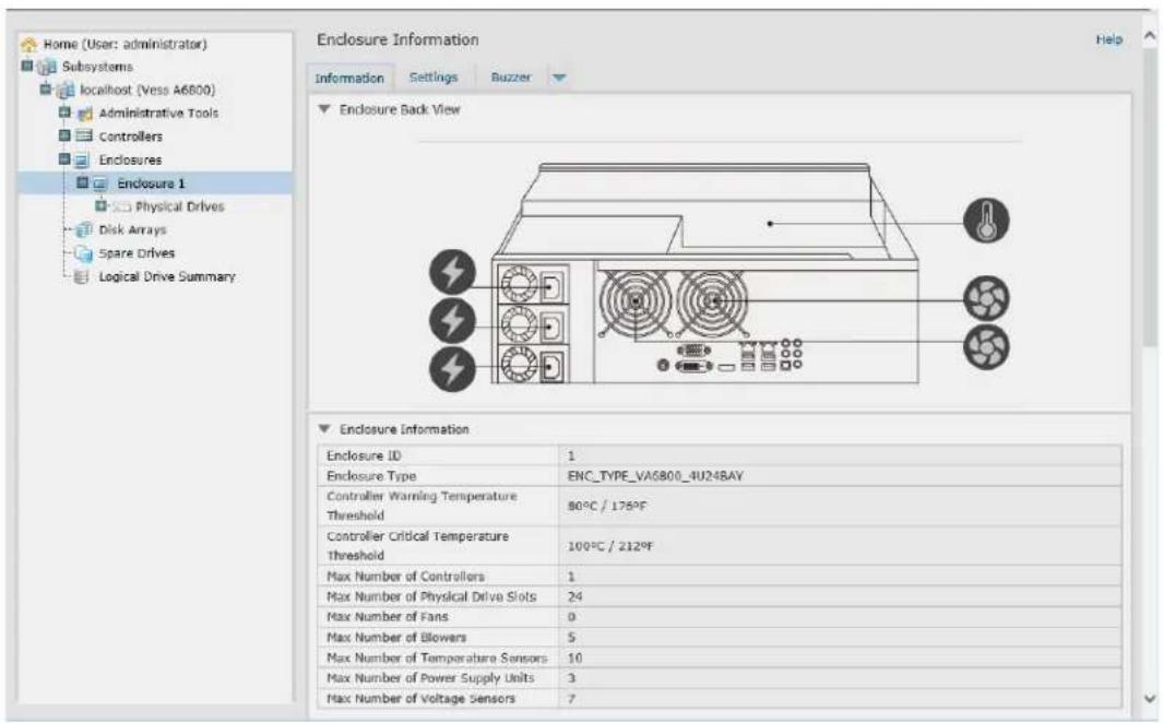
ENCLOSURE INFORMATION
The Enclosure Information read-only display menu provides key real-time information about current hardware status of the enclosure. Click on the expanders buttons to reveal current conditions and status of the enclosure, power supplies, fans, blowers, temperature sensors and voltage sensors. Move the cursor over the icons in the virtual enclosure displayed at the top of the menu to see current status and relevant conditional statistics for the fans, power supplies, and temperature sensors.
Enclosure Information display
ENCLOSURE TEMPERATURE SENSOR SETTINGS
The temperature threshold settings are used to send event notices when the internal temperature reaches a high level. To set enclosure temperature thresholds, click on the enclosure in Tree View, then click on the
Settings tab to view the Enclosure Settings menu. There are two thresholds to configure:
- Controller Warning Temperature Threshold [80-95 C°] — If the enclosure temperature reaches this threshold, a warning message is sent and an event is recorded in the event log.
- Controller Critical Temperature Threshold [100-105 C°] — If the enclosure temperature reaches this threshold, a warning message is sent, an event recorded is recorded in the event log.
BUZZER SETTINGS
The audible enclosure alarm buzzer can be enabled or disabled.
To enable or disable the buzzer, click on the enclosure in Tree View, then click on the Buzzer menu expander, scroll to Settings and click the check Enable Buzzer option box. Click the Submit button.
PHYSICAL DRIVES
The Physical Drives menus are used to view information and statistics about physical hard drives installed in the enclosure and to set Global Settings for hard drives. To see the Physical Drives List, expand the individual Enclosure icon in Tree View to see the Physical Drives icon for the enclosure. To display the information for any populated slot, you can expand the Physical Drives icon in Tree View to reveal links to each slot, or click on the slot in the Physical Drives List, or click on the populated slot in the virtual enclosure displayed in the menu.
View individual physical drive information

The information listed for individual physical drives includes:
Physical Drive Information
- Physical Drive ID
- Configuration Status
- Location [Enclosure # Slot #] - Model
- Alias
- Drive Interface
• Physical Capacity • Serial Number - Configurable Capacity
- Firmware Version
• Used Capacity • Protocol Version - Block Size [Bytes]
- Visible To [Controller #]
- Operational Status
Advanced Physical Drive Information
- Write Cache [Enabled/Disabled] - Command Queuing [Enabled/Disabled]
- Read Look Ahead Cache [ Enabled/ Disabled]
- Queue Depth
- Maximum Multiple DMA Mode Supported
• SMART Feature Set • Maximum Ultra DMA Mode Supported
• SMART Self Test • DMA Mode - SMART Error Logging
- Drive Temperature [C^/F^]
• Command Queuing Support • Reference Drive Temperature
Disk Arrays and Logical Drives
Disk arrays and logical drives are created and managed using the Disk Arrays menu. Use the Array Configuration menu to view the Disk Array List, and to create and delete disk arrays on the enclosure. Expand the Disk Arrays icon in Tree View to view menu links for existing arrays. Each array icon can be expanded again to see the Logical Drives icon, and this can be expanded to see each logical drive icon.
For a detailed description of how to create disk arrays and logical drives using Promise Management GUI, please refer to the Quick Start Guide.
Use the top-level Disk Arrays menu to view the Disk Array List, to delete existing arrays, and to create new disk arrays using the Automatic, Express, or Advanced disk array creation menus. Note that there must be physical drives available in order to use any of the disk array creation menus.
View information for existing disk arrays by clicking on the icon in Tree View or the array name in the Disk Array List. Each individual array menu is used to create and delete logical drives, to change settings (Alias and start/stop PDM, Media Patrol and Power Management) for the array, or to start Background Activities including PDM, Rebuild and Transition.
Individual Disk Array menu

Information in the Disk Array menu includes:
- Disk Array ID [#]
- Alias
• Operational Status (see below)
• Total Physical Capacity - Configurable Capacity
• Free Capacity [Bytes]
• Max Contiguous Free Capacity [Bytes]
• Media Patrol [Enabled/Disabled]
- Drive Health Polling
• Power Management [Enabled/Disabled]
• Number of Physical Drives
• Number of Logical Drives
• Available RAID Levels
Other lists in this menu:
• Physical Drives in the Disk Array
• Logical Drives in the Disk Array
• Available Spare Drives to the Disk Array
Disk Array Operational Status
OK – This is the normal state of a logical drive. When a logical drive is Functional, it is ready for immediate use. For RAID Levels other than RAID 0, the logical drive has full redundancy.
Synchronizing – This condition is temporary. Synchronizing is a maintenance function that verifies the integrity of data and redundancy in the logical drive. When a logical drive is Synchronizing, it will function and your data is available. However, access will be slower due to the synchronizing operation.
Critical / Degraded – This condition arises as the result of a physical drive failure. A degraded logical drive will still function and your data is still available. However, the logical drive has lost redundancy (fault tolerance). You must determine the cause of the problem and correct it.
Rebuilding – This condition is temporary. When a physical drive has been replaced, the logical drive automatically begins rebuilding in order to restore redundancy (fault tolerance). When a logical drive is rebuilding, it will function and your data is available. However, access will be slower due to the rebuilding operation.
LOGICAL DRIVE MANAGEMENT
Logical drives are made from disk arrays. In the Tree, you can see a graphic representation of the logical drives that belong to each array. The Logical Drive List can be accessed in Tree View by expanding the under Disk Arrays and clicking on the Logical Drives icon for any existing disk array, or simply click on the Logical Drive Summary icon for the Subsystem.
Click on any Logical Drive (LD) in the list to view Information and Statistics, to change Settings (Alias, Read Policy, Write Policy), to start Background Activities (Initialization, Redundancy Check), or to view the Check Table for the LD.
Information displayed in the menu includes:
- Logical Drive ID
- Alias
- Raid Level
- Operational Status
- Capacity
• Physical Capacity
• Number of Axles [#]
• Number of Used Physical Drives [#] - Stripe Size
- Sector Size [Bytes]
- Disk Array ID
- Read Policy
- Write Policy
- Current Write Policy
- Serial Number
- WWN
• Synchronized [Yes/No]
• Tolerable Number of Dead Drives Per Axle - Parity Pace
- Codec Scheme
SPARE DRIVES
When a physical drive in a disk array fails and a spare drive of the same type and adequate capacity is available, the disk array will begin to rebuild automatically using the spare drive.
In Tree View, click on the Spar Drive icon to see the Spare Drives List, or to create or delete an existing spare drive. Click on any spare drive in the list to information about the drive. Spare Drive Information includes:
- Spare Drive ID
• Physical Drive ID - Spare Type
- Revertible [Yes/No]
- Operational Status
- Spare Check Status
• Physical Capacity - Configurable Capacity
- Block Size
- Drive Interface
- Model
- Location
- Configuration Status
- Serial Number
- Firmware Version
RUNNING SPARE CHECK
A Spare Check verifies the operational status of your spare drives. You can also schedule a Spare Check.
To check a spare drive:
- Click the Spare Drives icon.
- Click the Spare Check tab.
- From the Physical Drive drop-down menu, choose the spare drive you want to check. Or choose All to check all the spare drives at the same time.
- Click the Submit button.
The results of the Spare Check appear under Spare Check Status in the Information tab. "Healthy" means normal condition.
LOGICAL DRIVE SUMMARY
The Logical Drive Summary displays a list of all logical drives in the Subsystem. This list does not arrange the logical drives under the disk array to which they belong nor under the enclosure in which they are located. The menu functions in the same way as the Logical Drives menu discussed in “Logical drive management” on page 72
MAINTENANCE
This chapter covers the following topics:
• "Replacing a Power Supply"
REPLACING A POWER SUPPLY
The Vess A6600 systems can accommodate two AC power supplies in the bay at the rear of the chassis. The Vess A6800 systems can accommodate three AC power supplies in the bay at the rear of the chassis. Each unit provides up to 550 Watts of power. Only a single power supply is required for operation, with the second power supply purely as a redundant, load-sharing backup. It can be removed without affecting system operation.
Installing and Removing the Power Supply
- Align the power supply unit with the power supply slot. Ensure that the LED appears on the left when you are installing the power supply unit.
- Carefully slide the PSU all the way into the power supply bay until it clicks into place.
REMOVING THE POWER SUPPLY UNIT
To remove a failed power supply, please first identify the failed power supply.
- Hold onto the power supply handle while pressing the locking lever towards the power supply handle.
-
Pull to remove the power supply from the chassis.
-
Before replacing the power supply, power off the server, unplug the power cord, and disconnect all wiring from the power supply.
- In a redundant system, you do not need to power down the server.
TROUBLESHOOTING
This section focuses on how to address issues that might appear during the lifetime of the Vess A6000 enclosure. Common issues that customers might see include hard drive problems and how to know when there is a problem with a hard drive, and how to create and send a service report to technical support.
If a hard drive has errors, is about to fail or has already failed, it will need to be replaced. Follow the instructions in "Installing Disk Drives" on page 25 to swap out bad hard drives.
This chapter includes the following troubleshooting sections and related information:
• "How do I know when a drive is failing?"
• "How to Rebuild a Disk Array"
• "The Alarm Buzzer is Sounding, what does this mean?"
• "How to disable the alarm buzzer"
• "How to Save a Service Report"

Note
Hard drives on the Vess A6000 models can be hot swapped, that is, they can be replaced without first shutting down the system.

Note
Follow the instructions in "Installing Disk Drives" on page 25 to swap out bad hard drives.
How do I know when a drive is failing?
There are many options to determine the health of physical hard drives. In Web PAM PROe, you can either use the Event Frame or go to the Physical Drives information display. Or you can simply check the status LED of the drives on the device.
CHECK DRIVE STATUS LEDs
The quickest way to check drive status if you are near the device is to simply look at the hard drive status LED indicators, then use the other LED indicators to help diagnose any problems that might exist.
Vess A6600 front

Status LED behavior
| HDD Status | The Disk Status LED displays GREEN when a drive is configured and working properly. When the lights are RED the HDD requires manual replacement. When ORANGE is observed it indicates background RAID activity on this particular HDD and no user action is required. |
| System Status | Lights GREEN when healthy, RED if there is a critical problem (LD offline, fan malfunction, voltage out of range, system temperature alert), blinks RED for HDD high temperature alert remains dark when not ready. This will be RED if a hard drive has failed or has critical errors. Replace the drive corresponding to the RED HDD Status indicator. |
| Global RAID Status | Lights GREEN when healthy or RED if any RAID volume is offline, ORANGE for critical state of any logical drive. If a hard drive has failed, this will be ORANGE. In this case, it will be necessary to replace the affected drive and rebuild the affected RAID volume. |
The Vess A6000 models have hard drive status and activity LEDs on each drive carrier. Also check the status indicators on the right side of the front of the device for clues about what is wrong.
Hard drive carrier front LEDs

Vess A6800 status LEDs on right side of front

CHECK DRIVE STATUS IN MANAGEMENT GUI
To see the Event Frame, click Show Event Frame in the Web PAM PROe Header and check the list under Device, any physical drive problems will be indicated in the right most column, the top rows of the event table list the installed physical drives.
Also, in Management GUI, you can go to the Physical Drives List. To see the Physical Drives List, expand the individual Enclosure icon in Tree View to see the Physical Drives icon for the enclosure. To display the information for any populated slot, you can expand the Physical Drives icon in Tree View to reveal links to each slot, or click on the slot in the Physical Drives List, or click on the populated slot in the virtual enclosure displayed in the menu.
View physical drive list
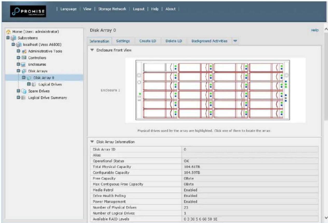
View individual physical drive information


Note
In order that hard disk problems can be anticipated and dealt with smoothly, it is highly recommended to make sure that Media Patrol is enabled and running and Auto Rebuild is enabled if you are not using a spare drive. If using a spare drive, make sure it is healthy and available.
ANTICIPATING HARD DRIVE PROBLEMS
It is recommended that you always keep a healthy spare drive installed, and run Media Patrol as a background activity so a failing hard drive can migrate data to the spare before the status turns critical.
In Web PAM PROe, Media Patrol is enabled or disabled using the Background Activities menu, you can also create a schedule to run Media Patrol.
Enable Media Patrol
![Home (User: administrator) Subsystems localhost (Vess A6800) Administrative Tools Centrollers Enclosures Enclosure 1 Disk Arrays Disk Array 0 Logical Drives Logical Drive 0 Spare Drives Logical Drive Summary Background Activities Information Settings Event Background Activities Scheduler Lock Background Activity Settings Rebuild Rate High Background Synchronization Rate Low Logical Drive Initialization Rate Medium Redundancy Check Rate Medium Migration Rate High FOM Rate High Transition Rate Medium Reassigned Block Threshold [1-512] 32 Blocks Error Block Threshold [1-2048] 32 Blocks Enable Media Patrol ✓ Enable Auto Rebuild ✓ Reset Submit Cancel](/content/2026/05/1002357/images/a3bbe60f57463ca3b4b7bc88c25c6e62880abf6259af319193719f690736e079.jpg)
- To enable Media Patrol, click on Background Activities in the Quick Links menu in the Home page, or, click on the Subsystem in Tree View then click on the Background Activities menu tab, click the expander to the right of the tab and select the Settings option from the pull down menu. Click to check the Enable Media Patrol option. Notice also that the Auto Rebuild option is here as well. If you want to automatically begin rebuilding a logical drive as soon as a faulty drive is replaced, make sure this option is enabled.
- To begin running Media Patrol manually, click on the menu expander to the right of the Background Activities tab and scroll down and select Start Media Patrol to see the Start Media Patrol menu. Then click on the Start button.
- To schedule Media Patrol, click on the menu expander to the right of the Scheduler tab and scroll down and select Add Media Patrol Schedule to open the schedule menu. Use this menu to add a Media Patrol schedule.
REBUILDING A DISK ARRAY
When you rebuild a disk array, you are actually rebuilding the data on one physical drive.
- When a physical drive in a disk array fails and a spare drive of adequate capacity is available, the disk array begins to rebuild automatically using the spare drive.
- If there is no spare drive of adequate capacity, but the Auto Rebuild function is ENABLED, the disk array begins to rebuild automatically as soon as you remove the failed physical drive and install an unconfigured physical drive in the same slot. See “Making Rebuild Settings”
- If there is no spare drive of adequate capacity and the Auto Rebuild function is DISABLED, you must replace the failed drive with an unconfigured physical drive, then perform a Manual Rebuild.
How to Rebuild a Disk Array
When a physical drive is indicated to be degraded or in critical state, the array that contains that drive needs to be rebuilt. If you are not using Auto Rebuild (requires a Spare Drive), then you must rebuild the array manually after the affected drive has been replaced. Follow the instructions here to rebuild an array.
You will know that a logical drive is critical by looking at the Operational Status in the Logical Drive Information display.
Logical Drive Information

To begin rebuilding the drive, go to the Local Host menu, the Background Activities and move the cursor to select Start Rebuild. A new menu appears.
Background Activities - Start Rebuild 1
![Home (User: administrator) Subsystems localhost (Vers A6800) Administrative Tools Controllers Enclosures Exposure 1 Disk Arrays Disk Array 0 Logical Drives Logical Drive 0 Spare Drives Logical Drive Summary Background Activities Information Settings Event Background Activities Scheduler Lock Background Activity Settings Rebuild Rate Background Synchronization Rate Logical Drive Initialization Rate Redundancy Check Rate Migration Rate PDM Rate Transition Rate Reassigned Block Threshold [1-512] Error Block Threshold [1-2048] Enable Media Patrol Enable Auto Rebuild Settings Start Media Patrol Start Rebuild Start PDM Start Transition Start Initialization Start Redundancy Check Reset Submit Cancel h v dum dum h sum Blocks Blocks](/content/2026/05/1002357/images/36667f3e85bd3f7a9724e18fc6175d8d7909eb95f1f57c0e36584672b1897734.jpg)
Now determine the source and target for the rebuild. In the new menu, choose the Source Physical Drive and Target Physical Drive from the menus, and click on the Submit button.
Background Activities - Start Rebuild 2

The progress of the rebuild is displayed in the Background Activities information display.
Background Activities - Rebuild Status
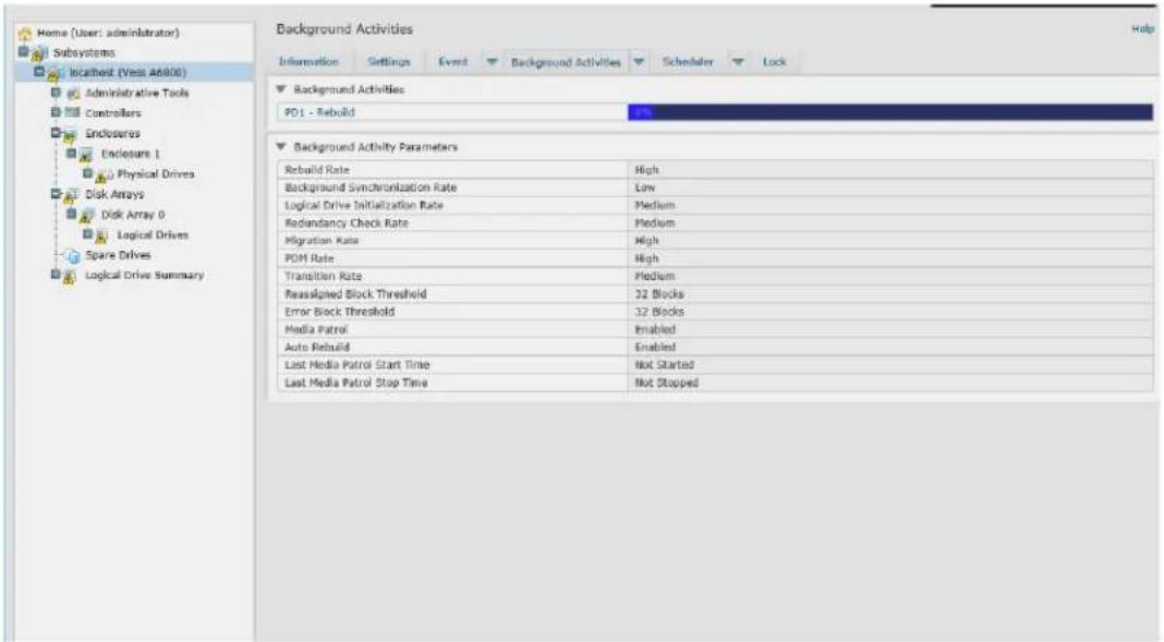
How to Save a Service Report
A Service Report is a detailed report covering the configuration and status of all components in your RAID system. A support technician or field engineer might request a service report for the purpose of diagnosis and troubleshooting.
Subsystem Information - Save Service Report
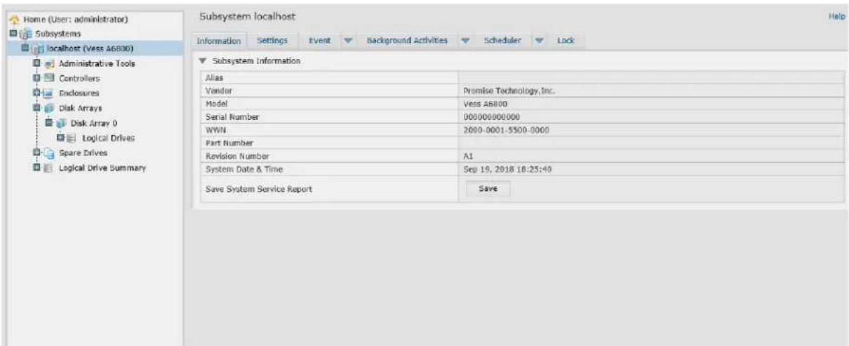
To save a system configuration file:
- Click on the Subsystem icon (IP address and device name) in Tree View to open the Subsystem Information display.
- Click the Save button in the Save System Service Report row of the information display.
Information for the report is gathered and compiled. This action takes up to a few minutes, depending on the size of your RAID system.
- Determine where you want to store the file on the Host PC, then click the Save button in the pop-up menu.
The report saves to your Host PC as a compressed HTML file.
- Double-click the downloaded file to decompress it.
- Double-click the report to open it in your default browser.
Once you have the service report file, you can email it to a Technical Support representative.
The Service Report includes the following topics:
- About – Report utility
• BBM Info – Bad Block Manager
• BGA Summary – Status and settings - Buzzer Info
- Controller Info
- Disk Array Info
- Disk Array Dump info
- Disk Array Verbose Info
- Enclosure Info
- Error Table Info
• Event Info - NVRAM
• Event Info - Runtime - LogDrive Info – Basic logical drive information
- LogDrive Dump Info – Diagnostic information
- Logical Drive Verbose Info – Full logical drive information
• Network Info – Virtual port
• Phydriv Info – Basic physical drive information
• Phydriv Verbose Info – Full physical drive
• SWMGT Info – Software management
• Service Setting – Email
• Service Setting – Webserver
- Spare Info – Basic spare drive information
- Spare Dump Info – Diagnostic information
- Spare Verbose Info – Full spare Drive information
- Statistic Info
- Subsystem info
- User Info
THE ALARM BUZZER IS SOUNDING, WHAT DOES THIS MEAN?
When you first power-up the Vess A6000 system beeps twice to show normal operation.
The audible alarm sounds at other times to inform you that the system needs attention. But the buzzer alarm is not specific. Check the device LEDs and Events displays or logs for more information.
When the alarm sounds:
- Check the front and back of the enclosure for red or orange LEDs.
• If email notification is enabled, check for new messages. - Check the event log.
When a continuous tone sounds, there are multiple alarm patterns sounding at the same time (see example number 1 illustrated below).
Alarm buzzer patterns

bar
| Row | Time (s) | |---|---| | 1 | 25 | | 2 | 25 | | 3 | 25 | | 4 | 25 | | 5 | ∞ s |Other alarm patterns include three short buzzes followed by a longer silence, then repeated (example number 2 above). This can indicate a serious problem that requires immediate action such as high enclosure temperature or the system fan is not installed. If you hear this, check the System Status LED. If these are normal, it might indicate a physical drive problem, or a power supply problem. Check the event log for more information.
Pattern number 3 above might indicate an LD offline. Pattern number 4 might be an
LD critical or bad sector on a physical disk.
How to Disable the alarm buzzer
To disable the buzzer with Web PAM PROe, open Web PAM PROe, click on the enclosure in Tree View, then click on the Buzzer menu expander, scroll to Settings and click the Enable Buzzer option box to remove the check mark. Click the Submit button.
FAQ
Q: What is Vess A6000 Series Storage Appliance for Video Surveillance?
A: The Vess A6000 platforms are engineered specifically to be the best solution for midsize to large IP video surveillance deployments.
Q: How does it work for surveillance video recording?
A: The Vess A6000 comes complete with your choice of Windows OS, a leading Video Management Software suite, or Disk Drives, minimizing the integration and installation process. Users no longer need an extra PC/server, add-on cards, or a separate connected storage for a complete video surveillance system; the Vess A6000 Series Storage Appliance for Video Surveillance does it all!
Q: What should I do if the device OS fails?
A: Unlike regular COTS servers that come with standard Windows OS, the Vess A6000 provides an embedded version that requires a certain process to rebuild the OS image. Users need to consult Promise tech support and follow installation guide to complete the setup.
Q: What's the standard warranty of Vess A6000?
A: We provide the same standard three (3) years hardware warranty from the time of the delivery of the product to the original end user.
Q: Can I purchase extended warranty package to Vess A6000?
A: Yes, we provide 2-year extended warranty program that uses the same order and support practice as Vess A6000 product series.
APPENDIX: DRIVER INSTALLATION AND UPDATE
This appendix provides instructions for installing or updating the driver for the Promise RAID engine, as well as Management GUI, the management GUI for the Promise Vess A6000 Series.
Follow instructions in the ReadMe.txt file to install the latest hardware driver for the RAID and the latest Management GUI version.
UPDATE/INSTALLATION REQUIREMENTS
USB FLASH DRIVE
A USB flash drive containing the update package is needed. Follow the instructions in the ReadMe.txt file to download the compressed file package and place a copy of the uncompressed file on the USB flash drive.
UPDATE/INSTALL THE DRIVER
Follow instructions in the ReadMe.txt file for complete the installation or update of the driver.
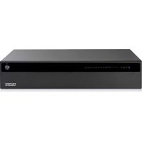
- Vess A6600 (VES0603)
- Vess A6800 (VES0604)
- Storage Appliance for Video Surveillance Product Manual
- Warning
- Caution
- Important
- Note
- Federal Communications Commission notice
- Class A equipment
- Modification
- Notices for New Zealand and Australia
- Notices for European Union
- CONTENTS
- INTRODUCTION .... 1
- SPECIFICATIONS 2
- HARDWARE....4
- HARDWARE SETUP 12
- UNPACKING 13
- MOUNTING THE ENCLOSURE IN A RACK....14
- INSTALLING DISK DRIVES 19
- MANAGEMENT PATH CONNECTION 24
- CONNECT THE POWER 25
- POWER ON ENCLOSURE....26
- PROMISE MANAGEMENT GUI....29
- LOGGING INTO PROMISE MANAGEMENT GUI....29
- USING THE PROMISE MANAGEMENT GUI INTERFACE 33
- CHOOSING A DISPLAY LANGUAGE....35
- SUBSYSTEM MANAGEMENT....38
- BACKGROUND ACTIVITIES 39
- MANAGE BACKGROUND ACTIVITIES SETTINGS ....40
- EVENT LOGS 47
- ADMINISTRATIVE TOOLS 48
- USER MANAGEMENT 49
- MAKING USER SETTINGS 49
- CREATING A USER....51
- TROUBLESHOOTING....77
- How do I know when a drive is failing? 78
- HOW TO SAVE A SERVICE REPORT....86
- FAQ....90
- APPENDIX: DRIVER INSTALLATION AND UPDATE....91
- UPDATE/INSTALL THE DRIVER 91
- INTRODUCTION
- HARDWARE
- FRONT PANEL HARDWARE
- FRONT OF VESS A6600
- SECURE COVER
- FRONT PANEL LEDs
- REAR PANEL HARDWARE
- Vess A6000 Rear Panel Components
- Vess A6000 Rear Panel LED INDICATORS
- Vess A6000 Rear Panel Connections
- HARDWARE SETUP
- UNPACKING
- PACKING LIST
- MOUNTING THE ENCLOSURE IN A RACK
- Cautions
- MOUNTING ENCLOSURE IN A RACK
- INSTALLING OR REMOVING THE SECURITY COVER
- INSTALLING DISK DRIVES
- NUMBER OF DRIVES REQUIRED
- DRIVE SLOT NUMBERING
- REMOVING THE DRIVE CARRIER
- Vess A6600/A6800 Disk carrier with HDD installed - front view
- INSTALLING 3.5" DISK DRIVE IN THE CARRIER
- INSTALLING 2.5" DISK DRIVE IN THE CARRIER
- MANAGEMENT PATH CONNECTION
- NETWORK CONNECTION
- CONNECT THE POWER
- POWER ON ENCLOSURE
- FRONT PANEL LED BEHAVIOR
- CONNECT TO ISCSI STORAGE AREA NETWORK (SAN)
- PROMISE MANAGEMENT GUI
- LOGGING INTO PROMISE MANAGEMENT GUI
- LOGGING IN AT THE ENCLOSURE
- LOGGING IN OVER THE NETWORK
- Regular Connection
- Secure Connection
- LOGIN SCREEN
- USING THE PROMISE MANAGEMENT GUI INTERFACE
- Promise Management GUI interface - Subsystem home page
- USING THE HEADER
- USING TREE VIEW
- USING MANAGEMENT VIEW
- CHOOSING A DISPLAY LANGUAGE
- VIEWING THE EVENT FRAME
- LOGGING OUT OF PROMISE MANAGEMENT GUI
- SUBSYSTEM MANAGEMENT
- BACKGROUND ACTIVITIES
- VIEW CURRENT BACKGROUND ACTIVITIES
- VIEW BACKGROUND ACTIVITIES PARAMETERS SETTINGS
- MANAGE BACKGROUND ACTIVITIES SETTINGS
- REBUILD SETTINGS
- Rebuild Rate
- Background Synchronization Rate
- LOGICAL DRIVE INITIALIZATION
- Logical Drive Initialization Rate
- REDUNDANCY CHECK
- Redundancy Check Rate
- PDM
- PDM Settings
- TRANSITION
- Transition Rate
- MEDIA PATROL
- Media Patrol Settings
- MANAGING ACTIVITY SCHEDULES
- Add or Delete an activity schedule
- VIEW OR MODIFY AN EXISTING ACTIVITY SCHEDULE
- EVENT LOGS
- ADMINISTRATIVE TOOLS
- RESTORE FACTORY DEFAULT SETTINGS
- Firmware Default Settings
- Software Default Settings
- CLEAR STATISTICS
- USER MANAGEMENT
- VIEWING USER INFORMATION
- MAKING USER SETTINGS
- MAKING YOUR OWN USER SETTINGS
- CHANGING YOUR OWN PASSWORD
- CREATING A USER
- To create a user:
- LIST OF USER PRIVILEGES
- DELETING A USER
- VIEW NETWORK SETTINGS
- SOFTWARE MANAGEMENT
- IMPORTING A CONFIGURATION SCRIPT
- EXPORTING A CONFIGURATION SCRIPT
- SAVING A SERVICE REPORT
- The Service Report includes the following topics:
- EMAIL SERVICE
- STOP EMAIL SERVICE
- RESTARTING EMAIL SERVICE
- EMAIL SETTINGS
- SENDING A TEST EMAIL MESSAGE
- PERFORMANCE MONITORING
- Information
- Read/Write
- CONTROLLERS
- VIEW CONTROLLER INFORMATION
- Controller information includes:
- Click the Advanced Information menu expander to view advanced information.
- Advanced controller information includes:
- VIEWING CONTROLLER STATISTICS
- CONTROLLER SETTINGS
- To make controller settings:
- ENCLOSURES
- LOCATE AN ENCLOSURE
- ENCLOSURE INFORMATION
- ENCLOSURE TEMPERATURE SENSOR SETTINGS
- BUZZER SETTINGS
- PHYSICAL DRIVES
- Physical Drive Information
- Advanced Physical Drive Information
- Disk Arrays and Logical Drives
- Individual Disk Array menu
- Disk Array Operational Status
- LOGICAL DRIVE MANAGEMENT
- SPARE DRIVES
- RUNNING SPARE CHECK
- LOGICAL DRIVE SUMMARY
- MAINTENANCE
- REPLACING A POWER SUPPLY
- REMOVING THE POWER SUPPLY UNIT
- TROUBLESHOOTING
- How do I know when a drive is failing?
- CHECK DRIVE STATUS LEDs
- CHECK DRIVE STATUS IN MANAGEMENT GUI
- View individual physical drive information
- ANTICIPATING HARD DRIVE PROBLEMS
- Enable Media Patrol
- REBUILDING A DISK ARRAY
- How to Rebuild a Disk Array
- How to Save a Service Report
- Subsystem Information - Save Service Report
- THE ALARM BUZZER IS SOUNDING, WHAT DOES THIS MEAN?
- How to Disable the alarm buzzer
- FAQ
- APPENDIX: DRIVER INSTALLATION AND UPDATE
- UPDATE/INSTALLATION REQUIREMENTS
- USB FLASH DRIVE
- UPDATE/INSTALL THE DRIVER
Brand : Promise Technology
Model : Vess A6800
Category : Security Camera