
VN-T216U - Surveillance Camera JVC - Free user manual and instructions
Find the device manual for free VN-T216U JVC in PDF.
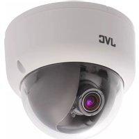


| Product Type | Fixed HD IP Dome Camera |
| Brand | JVC |
| Model | VN-T216U |
| Image Sensor | 1/2.7-type Mega-pixel CMOS |
| Minimum Illumination | Color: 0.6 lx, B/W: 0.6 lx (50%) |
| Lens Type | 1/3-type 3-9mm, F:1.2 |
| Day/Night Mode | Easy D/N (Auto, Color, B/W) |
| Video Compression | H.264, MPEG4, MJPEG |
| Maximum Resolution | 1080P (1920 x 1080) |
| Frame Rate | Up to 25 fps (PAL) / 30 fps (NTSC) |
| Power Supply | PoE IEEE 802.3af Class 0, DC12V, AC24V |
| Power Consumption | PoE 0.13A, DC12V 550mA |
| Dimensions (D x H) | 126 mm x 106 mm |
| Weight | 490 g |
| Operating Temperature | -10°C to 50°C |
| Storage Temperature | -20°C to 60°C |
| Network Interface | RJ-45, 100BASE-TX/10BASE-T |
| Supported Protocols | IPv4, HTTP, TCP, RTSP, RTP, ICMP, UDP, IGMP, RTCP, FTP, DNS, DHCP, ARP |
| ONVIF Compatibility | Yes (pass compliance test tool) |
| Audio | Line in/out (removable terminal block) |
| Alarm Input/Output | 1 in / 1 out (Alarm out: 0.5A / AC120V max) |
| Onboard Storage | SDHC card slot (FAT32, recommended Class 10) |
| Adjustment Range | 3-axis gimbals: Pan 360°, Tilt, Horizontal Rotation (max 360°) |
| Mounting | Wall or ceiling mount with safety wire |
| Maintenance | Clean dome cover with soft dry cloth; do not use volatile solvents |
| Spare Parts / Repairability | No user-serviceable parts; contact qualified technician for service |
Frequently Asked Questions - VN-T216U JVC
User questions about VN-T216U JVC
0 question about this device. Answer the ones you know or ask your own.
Ask a new question about this device
Download the instructions for your Surveillance Camera in PDF format for free! Find your manual VN-T216U - JVC and take your electronic device back in hand. On this page are published all the documents necessary for the use of your device. VN-T216U by JVC.
USER MANUAL VN-T216U JVC
Contents
Contents of this manual....2
Cautions and Warnings 2
FCC Compliance Statement....3
Manufacturer's Declaration of Conformance....4
Europe....4
1 About This Document....5
Overview of Contents....5
2 Product Overview....6
Camera Overview....6
Camera Parts and Definitions 6
3 Installation and Connections....9
Before You Begin....9
Unpack Everything....9
Equipment Required....9
Camera Installation....9
Disassembling the Camera....10
Connecting the Power Wiring....10
Adjusting the Camera Position....11
Adjusting Zoom and Focus 12
Mounting the Camera 12
Locking the Camera 14
Network Camera Diagram....14
Hardware/Software Requirements 15
Connecting the Camera to a Personal Computer....16
Setting IP 16
Connecting the Camera to a Personal Computer....16
4 Overview of Navigation and Controls 20
Live View 20
Image Parameters 21
Basic....21
Compression....26
Mask Zone....31
Alarm 33
SD Recording....34
E-mail Notification....35
Audio 37
Network Settings....38
Basic....38
FTP Server 39
RTSP 40
Https 41
Admin Function 41
Administrator 41
User List....42
Date/Time 42
Update....44
Configuration....44
Event Log....45
Information......46
Miscellaneous 47
5 Specification....48
Contents of this manual
- Windows, Internet Explorer, DirectX and FAT32 are registered trademarks of Microsoft Corporation in the U.S. • Pentium is a registered trademark of Intel Corporation in the U.S. • NVIDIA and GeForce are trademarks or registered trademarks of NVIDIA Corporation in the U.S. • AMD, ATI and Radeon are trademarks of Advanced Micro Devices Inc. in the U.S.
- Product names of other companies described in this manual are trademarks or registered trademarks of the respective companies. Symbols such as ™, ® and © are omitted in this manual.
- Design, specifications and other contents described in this manual are subject to change for improvements without prior notice.
Cautions and Warnings

Installation and servicing should be performed only by qualified and experienced technicians to conform to all local codes and to maintain your warranty.

DC12V / AC24V models require the use of CSA Certified/UL Listed Class 2 power adapters to ensure compliance with electrical safety standards. Power over Ethernet (PoE) should meet the IEEE802.3af PoE standards.
This product is intended to be supplied by a Listed Direct Plug-In Power Unit marked "Class 2" or Listed Adapter marked "L.P.S." (or "Limited Power Source") or PoE and rated output DC 12V, 0.55A minimum or AC 24V, 60Hz, 0.55A minimum or 48Vdc, 0.13A minimum. (for USA)
WEEE (Waste Electrical and Electronic Equipment).

Correct disposal of this product (applicable in the European Union and other European countries with separate collection systems). This product should be disposed of, at the end of its useful life, as per applicable local laws, regulations, and procedures.
Caution
Connect only one camera to the power line, AC24V/DC12V. Do not share the power line with other equipment. The power cable between power source and the camera must be under 3 m.
Caution
When powering the camera from AC24V, a UPS source should be considered to ensure satisfactory performance.
FCC Compliance Statement
Information to the user: This equipment has been tested and found to comply with the limits for a Class A digital device, pursuant to Part 15 of the FCC Rules. These limits are designed to provide reasonable protection against harmful interference in a residential installation. This equipment generates, uses, and can radiate radio frequency energy and, if not installed and used in accordance with the instruction manual, may cause harmful interference to radio communications. However, there is no guarantee that interference will not occur in a particular installation.
If this equipment does cause harmful interference to radio or television reception, which can be determined by turning the equipment off and on, the user is encouraged to try to correct the interference. For example, try reorienting or relocating the receiving antenna, increasing the separation between the equipment and receiver, or connecting the equipment to an outlet on a different circuit.
Caution
Changes or modifications not expressly approved by the party responsible for compliance could void the user's authority to operate the equipment.
This Class A digital apparatus complies with Canadian ICES-003.
Manufacturer's Declaration of Conformance
Europe
The manufacturer declares that the equipment supplied with this INSTRUCTIONS is compliant with the essential protection requirements of EMC directive 2004/108/EC and General Product Safety Directive GPSD 2001/95/EC, conforming to requirements of standards EN 55022 for emissions, EN 50130-4 for immunity.
1 About This Document
This instruction manual is designed to be a reference tool for the installation and operation of your system, including the camera's features, functions, and a detailed explanation of the menu tree.
Overview of Contents
This document contains the following chapters:
• Chapter 2, Product Overview, introduces the main functions and system requirements of the camera. • Chapter 3, Installation and Connections, provides detailed instructions on installing the camera and connecting wires. • Chapter 4, Overview of Navigation and Controls, introduces how to navigate in the main menu window and operate the controls.
2 Product Overview
Camera Parts and Definitions
Camera Overview

Camera Parts and Definitions
The dome camera is a fully integrated enclosure with camera and lens.

| 1 | Camera bottom case | 4 Loosen the screw to take off camera housing |
| 2 | Tilt adjustment bracket and thumbnails, notches(X2)Notches (x2) | 5 Camera housing |
| 3 | Inner liner | 6 Dome cover |
Routine Maintenance
- The dome cover is an optical part. Use a soft, dry cloth to remove any fingerprints or dust.
- Clean the camera housing with a soft, dry cloth. For more stubborn stains, use a cloth dampened with a small quantity of neutral detergent, then wipe dry.
Caution
Do not use volatile solvents such as alcohol, benzene, or thinners to avoid damaging the surface finish.
Connector Pin Definition
| DEFAULT RESET | DEFAULT | Return to factory default by pressing button for 5 seconds |
| RESET | System re-start |
VIDEO OUT is not available.

| Au. IN | Audio in | |
| GND | ||
| Au. OUT | Audio out | |
| GND | ||
| AL IN | Alarm in | |
| GND | ||
| COM | Alarm out | |
| AL OUT |
| DC12VAC24V±= | DC12V | IP camera can operate on DC12V / AC24V |
| AC24V |
Caution
For DC power supply use, make sure the polarity is correct to avoid malfunction and/or camera damage.
3 Installation and Connections
This chapter describes the installation and connection of the camera that can deliver video images and audio in real time using the Internet or an intranet.
Before You Begin
Please read these instructions carefully before you install and operate the camera.
Unpack Everything
• FIXED HD IP DOME CAMERA - WARRANTY CARD • SAFETY PRECAUTIONS - QUICK GUIDE • 2-PIN TERMINAL BLOCK for power input • 8-PIN TERMINAL BLOCK for alarm input/output • CD-ROM containing INSTRUCTIONS and IPFinder software - TEMPLATE : mounting template • 2 SCREW ANCHORs - 2 SCREWs
Equipment Required
The following tools might help you to complete the installation:
- Drill
- Screwdrivers
- Wire cutters
Camera Installation
Note
All installation and operations should conform to your local electricity safety rules.
Disassembling the Camera
- Remove the inner liner (3) by pulling it free of the two notches (2) in the housing.
- Set the camera housing (5) and liner (3) aside.

Connecting the Power Wiring
Connect the power supply cable to the power connectors.
| Caution | If using a DC supply, make sure the polarity is correct. Incorrect connection may cause malfunction and / or damage to the camera. |
| Note | Connectors and field wiring terminals for external Class 2 circuits provided with marking indicating minimum Class of wiring to be used. Class 2 shall be marked adjacent to the field wiring terminals |
Select one of the following options.
- For DC12V
Connect 12 V (-) to terminal = DC12V
Connect 12 V (+) to terminal = DC12V+
- For AC24V
Connect 24 V (~) cables to terminals ~AC24V.
- PoE
Connect the network cable to the RJ45 terminal using a switch.
Adjusting the Camera Position
The dome camera has three axes for positioning the camera. While monitoring the picture on the monitor, adjust the camera position as follows:
- Pan Adjustment (A) For Wall Mount and Tilted Ceilings Rotate the lens base (maximum 360°) until you are satisfied with the field of view.
- Horizontal Rotation (B) Rotate 3D assembly in the base. Do not turn assembly more than 360° as this assembly may cause the internal cables to twist and disconnect or break.
- Tilt Adjustment (C) After loosening the thumbnails, position the camera as desired, then finger-tighten the thumbnails to set the position.
Caution
Do not turn the lens more than 360° as this may cause internal cables to disconnect or break.

Adjusting Zoom and Focus
- Loosen the zoom lever (D) / locking screw by turning it counter-clockwise.
- Rotate the zoom ring to achieve the desired picture.
- Loosen the focus lever (E) / locking screw by turning it counter-clockwise.
- Rotate the focus ring to adjust the focus.
• If re-adjustment is necessary, repeat the steps above.
- Retighten the zoom lever (D) / locking screw and the focus lever (E) / locking screw.
Caution: Retighten the locking screws to prevent loss of adjustment.
Mounting the Camera
Place the mounting template (supplied) on the mounting surface and mark the holes.
Drill two holes, and then insert the screw anchors into the holes.
Take off the camera housing.
Connect the Safety Wire (fall prevention wire, not supplied) to the ceiling.
- Secure the camera bottom case (1) to the wall/ceiling with the TP4 x 15 mm tapping screws, supplied.
- Insert the power cable, LAN cable, and Audio cables.
- Adjust the view angle (zoom, focus, and Horizontal Rotation).
| Warning | To prevent the camera from falling off, ensure that it is connected to a firm place (ceiling slab or channel) using a Safety Wire (Fall Prevention Wire is not supplied). |
| Pay also careful attention to the length, strength, wiring, and material (insulating properties) of the fall prevention wire to be used. The length should be as short as possible within the permissible range of the mounting length. The wire should be strong enough to withstand the total weight of this product. (Pay also attention to the finishing at the end of the wire.) |
| Caution | Must be isolated camera and the wall/ceiling which are connected by the Safety Wire (Fall Prevention Wire). |
Note: Depending on the material of your mounting surface, you may require different screws and anchors than those supplied.

Safety Wire (fall prevention wire is not supplied). Please tighten a safety wire on a firm place as shown in the photo.

Locking the Camera
Use a soft, lint-free cloth to wipe the dome cover clean and remove fingerprints. Attach the inner liner and camera housing. Turn the power on after you have installed the camera.
Network Camera Diagram
Connection type 1:


Connection type 2:
![graph LR A["Device 1"] --> C["Switch"] B["Device 2"] --> C["Switch"] D["Device 3"] --> C["Switch"] C --> E["PC"]](/content/2026/05/1000527/images/70bdfa59141ce042e74991bc586857f8cbee42e937b2c9e6e14b8632496d3289.jpg)
Hardware/Software Requirements
Computer
Windows XP or Windows 7 as OS
Internet Explorer Version 6.0-8.0
CPU: Intel Pentium IV X2 2.4 GHz or equivalent AMD
Memory: 1G or above
Display adapter
Support DirectX9 for example
NVIDIA GeForce 6 Series above
ATI Mobility Radeon 9500 above.
Power Supply
This camera requires a DC12V/ AC24V/ PoE power supply. Please make sure you use the correct power supply before connecting to the camera.
Network Connector
Please use the RJ45 network connector for connecting the camera to your computer or switch.
Switch
If you want to monitor several cameras, the switch is required.
| Caution | To avoid damage to the camera, never connect more than one type of power supply (PoE IEEE802.3 Ethernet Class 0 or DC12V or AC24V power plug) at the same time. If using PoE, this camera is to be connected only to PoE networks without routing to external equipments. |
Connecting the Camera to a Personal Computer
Setting IP
This is a network-based camera and must be assigned an IP address first. The camera's default IP address is 192.168.0.2 and sub mask is 255.255.255.0. To change IP address, open Network Settings page described later.
If your network uses a DHCP server, an IP address can be assigned automatically from the DHCP server by enabling DHCP in the Network Settings page described later.
Connecting the Camera to a Personal Computer
- Connect the network cable to the camera and then turn on the camera's power.
- Set the personal computer's IP address. The camera's default IP address is 192.168.0.2 and sub mask is 255.255.255.0.
- Check that the camera and computer are connected by pinging the IP address you have set. To do this, start a command prompt (Windows: from the Start Menu, select Program. Then select Accessories and choose Command Prompt.) Type "Ping 192.168.0.2". If the message "Reply from..." appears, it means the connection is done.
- Start Internet Explorer and enter IP address: 192.168.0.2. A login window will appear. Enter the default user name: admin and password: jvc to log in.
Figure 3-1 Log on Screen
- Images of the camera can be viewed through Internet Explorer. Before viewing, follow these steps to enable the display.
a. Enable Cookies as shown below: --In Internet Explorer, click Internet Options on the Tools menu. --On the Privacy tab, move the settings slider to Low or Accept All Cookies. --Click OK.
b. Set Browser setting when proxy server is used when a proxy server is used. c. Change Security in Internet options as shown below:
--On tool menu, click Internet Option. --Press the Security tab. --If the camera operates inside the Intranet, click the Intranet icon. If the camera operates on the Internet, click the Internet icon. --Click Custom Level. This will open the Security Settings – Internet Zone screen. --Scroll down to the ActiveX controls and plug-ins radio buttons and enable all of them as shown in the illustrations:
• In Windows 7 only, Click 【Tools】→【Internet Options】→【Security】
○ Enable Protected Mode (require restarting Internet Explorer) → Unchecked

- Click 【Tools】→【Internet Options】→【Security】→【Custom level】

- Modify the configuration of IE's security setting as follow:
【Download signed ActiveX controls】→ Prompt (recommended)
【Download unsigned ActiveX controls】→ Prompt
【Initialize and script ActiveX not marked as safe for scripting】→ Prompt

【Automatic prompting for ActiveXcontrols】→ Enable

• 【Run ActiveXcontrols and plug-ins】→ Enable • 【Script ActiveX controls marked safe for scripting*】→ Enable
Only allow approved domains to use ActiveX without prompt
Disable Enable
Run ActiveX controls and plug-ins
Administrator approved Disable
Enable Prompt
Script ActiveX controls marked safe for scripting*
Disable Enable Prompt
- Type your IP address into the browser.
- Then you should be able to see the camera image screen.
4 Overview of Navigation and Controls
Live View
Live view is designed for general users to control the camera. In the left list it displays:
• Full Screen: Set Full screen • One shot: take a picture from live view • Audio In: get audio and output from PC. This menu is appeared by setting of Audio. • Audio Out: send audio and output from camera. This menu is appeared by setting of Audio. - Size 1:1 - Encoder No.1: Three streams are available for selection among H.264, MPEG-4 and MJPEG by setting of Encoder No.1. • Encoder No.2: This menu is appeared by setting of Encoder No.2.
Figure 4-1 Live View
Note
Keep the zoom level of IE as 100% to display normal live view.
Image Parameters
You can set up Basic Settings, Image Compression, Alarm, FTP, E-mail, SD Recording, and Audio for your network IP camera by clicking on Network Settings in the Settings menu.
Basic
Figure 4-1 Basic
Image Color
Automatic Exposure
Figure 4-2 Automatic Exposure
Automatic Exposure controls the light intensity of the picture. There are four types for adjustment. You can select Manual, AES (Automatic Electronic Shutter), Flicker-free 50Hz, and Flicker-free 60Hz for the camera depending on your application conditions. When Manual is chosen, the Shutter Speed can be adjusted.
Note: This camera controls shutter speed for automatic exposure.
Level
Set Automatic Exposure target from 1 to 10. This function works in AES mode.
Day-Night Settings
Set DAY/NIGHT function. Move the cursor to select Auto, Color, or BW mode. If Color mode is selected, you can force the camera to stay in DAY (COLOR) mode all day. If BW mode is selected, you can force the camera to stay in BW (NIGHT) mode all day.
Figure 4-3 Day-Night Settings
Brightness adjustment
Set picture brightness. You can adjust brightness level from 0 to 255.
Contrast
Set picture contrast. You can adjust contrast level from 0 to 255.
Saturation
Saturation describes the difference of a color from the gray of the same lightness. Increasing saturation deepens the colors of your images, making reds redder and blues bluer. You can adjust picture saturation level from 0 to 255.
Figure 4-4 Brightness adjustment, Contrast, Saturation
Shutter Speed
Figure 4-5 Shutter Speed
Set desired Shutter Speed from 1/25s to 1/10000s. When video type is PAL, the Shutter Speed can be set at 1/25, 1/50, 1/100, 1/120, 1/150, 1/200, 1/300, 1/500, 1/750, 1/1500, 1/5000 and 1/10000s. When video type is NTSC, the Shutter Speed can be set at 1/30, 1/60, 1/100, 1/120, 1/150, 1/200, 1/300, 1/500, 1/750, 1/1500, 1/5000 and 1/10000s.
Manual Gain
Set Manual Gain value from 0 to 24dB. The increment is 3.
Figure 4-6 Manual Gain
AWB
Figure 4-7 AWB
Set the white balance values to meet the environment condition for best color rendition.
"ON": The color of the camera is automatically adjusted according to external lighting conditions (ATW: Auto Tracking White Balance).
"OFF": Adjustable by the user manually; this is useful for specific conditions where AWB may not perform correctly. You can set the current R/B/D color temperature manually.
R Gain, B Gain, & D Gain
Figure 4-8 R Gain, B Gain, & D Gain
Set the manual gain values for R Gain, B Gain, GR Gain, GB Gain, and D Gain from 0 to 255. This function applies to manual lens only.
The red (R) gain is used to adjust the red color of the viewing image. It allows manual adjustment of the red gain according to user requirements, ranging from 0 to 255.
The blue (B) gain is used to adjust the blue color of the viewing image. It allows manual adjustment of the blue gain according to user requirements, ranging from 0 to 255.
The D gain is used to adjust the overall intensity of R gain and B gain. It allows manual adjustment of the blue gain according to user requirements, ranging from 0 to 255.
Noise Reduction
You can set the Noise Reduction value from 0 to 8.
Figure 4-9 Noise Reduction
Sharpness
Figure 4-10 Sharpness
Increasing the sharpness value will sharpen the edges and small features of camera images. You can set a Sharpness value for images from 0 to 255.
Backlight Compensation (BLC)
Figure 4-11 Backlight Compensation
Users can choose to turn this function ON or OFF.
Back Light Compensation is a function that achieves the brightness of the whole area to an optimum image level. Due to the intense light coming from the back of objects in the area expected to view, areas desired to see become dark and invisible. Therefore, this function is essential.
Picture
Figure 4-12 Picture
Picture Flip
Set image to be upside or down. Select "ON" or "OFF" to activate or deactivate the flip function.
Picture Mirror
Set image to be left or right. Select "ON" or "OFF" to activate or deactivate the mirror function.
| Note | Please click the “Save” button to save your settings. You can also click the left button “Reset to Default” to set all the data and options as defaults. |
Compression
- Select Compression.
- Configure the options as described in the table below.
- Click Save.
- Dual streams: Both Encoder No.1 & No.2 are available for selection.
- Functions of MJPEG, MPEG-4 and H.264 are effective. The video signal sent to the Web-Client from the camera has a number of settings that can be edited which affects the video as it's displayed in the Web-Client. The Compression Settings view enables you to configure settings such as Resolution, Frame Rate and Picture Quality. Besides, the network camera supports dual streams (for display and storage), which should be configured separately.
The user interface of Encoder No.1 is as follows:
Figure 4-13 Encoder No. 1
The table below elaborates on the above figure.
Table 4-1 Compression
| Compression | ||
| Item Function Choice Remark | ||
| Encoder No.1 | ||
| Compression Format | MJPEG | Set a default compression mode. |
| MPEG4 | ||
| H.264 | ||
| Resolution | 1080P720P | 1080P is the highest resolution and, QVGA is the lowest resolution.1080p only support H.264. |
| D1 | ||
| 4CIF | ||
| VGA | ||
| CIF | ||
| QVGA | ||
| Frame Rate | PAL:1- 25NTSC:1--30 | The frame rate is displayed per second.PAL: H.264 single stream: 1080P,720P,D1, 4CIF, CIF, VGA,QVGA@25fpsMPEG4/MJPEG: VGA,QVGA,@25fpsNTSC: H.264 single stream:1080P, 720P,D1, 4CIF, CIF, VGA,QVGA @30fpsMPEG4/MJPEG: VGA,QVGA,@30fps |
| Rate control mode | Variable bit rate | Choose the Bit Rate control selection based on user requirements. |
| Constant bit rate | ||
| Compression Ratio | Customized modeLowMid-lowStandardMid-highHigh | Low: this setting produces highest image quality while the file size increases.High: this setting produces lowest image quality while the file size decreases. |
| Quality value | MJPEG : 3-90 ;MPEG4 & H264 : 1-31 | selectable |
| Bit Rate | 256K512K1M2M3M4M6M8M | It's optional only when constant bit rate is chosen. Select the desired bit rate including 256, 512, 1M, 2M,3M ,4M,6M and 8M b/s.When resolution is not 1080P nor 720P, 4M is the maximum. |
| GOP | 1-64 | Select the GOP (Group of pictures) number from 1 to 64.If the number is bigger, recovery of the lost frames will be more difficult; If the number is smaller, it will increase the bite rate obviously and aggravate the network loading.The default value is 25. GOP will be differed by fps setting.The maximum GOP is differed by Bit Rate setting. |
| Profile | BaselineHigh Profile | Selectable (H.264 only) |
The user interface of Encoder No.2 is as follows:
Figure 4-14 Encoder No.2
The table below elaborates on the above figure.
Table 4-2 Compression
| Compression | ||
| Item Function Choice Remark | ||
| Encoder No.2 | ||
| Image Mode | MJPEGMPEG4 | Set H.264, MJPEG or MPEG4 as a default compression mode. |
| H264 | ||
| Resolution | no streamingD1/4CIF/CIF/VGA/QVGA | 1) Encoder No.1: 720p; Encoder No.2: D1/QVGA.2) Encoder No.1: VGA, QVGA; Encoder No.2: VGA, QVGA.3) Encoder No.1: D1, 4CIF, CIF. Encoder No.2: D1, 4CIF, CIF. |
| Frame Rate | PAL:1--25NTSC:1--30 | The frame rate that is displayed per second.PAL: H.264/MJPEG/MPEG-4: D1, QVGA @25fpsNTSC: H.264/MJPEG/MPEG-4: D1, QVGA@30fps |
| Rate control mode | variable bit rate | Choose the Bit Rate control selection based on user requirements. |
| constant bit rate | ||
| Compression Ratio | Customized modeLowMid-lowStandardMid-highHigh | Low: this setting produces highest image quality while the file size increases.High: this setting produces lowest image quality while the file size decreases. |
| Quality valueBit Rate | MJPEG : 3-90 ;MPEG4 & H264 : 1-31 | selectableSelect the desired bit rate including 256,512,1M,2M,3M,4Mb/s. |
| 256K | ||
| 512K | ||
| 1M | ||
| 2M | ||
| 3M | ||
| 4M | ||
| GOP | 1-64 | Select the GOP (Group of pictures) number from 1 to 64.If the number is bigger, recovery of the lost frames will be more difficult; If the number is smaller, it will increase the bite rate obviously and aggravate the network load. The default value is 25. GOP will be differed by fps setting.The maximum GOP is differed by Bit Rate setting. |
| Profile | BaselineHigh Profile | Selectable (H.264 only) |
| Note | The GOP and FPS of H.264: 1080P/720P, MPEG4: 720P can’t be setting lower than 5. |
| Note | If live view display abnormal after changing Camera's resolution, please adjust your computer's resolution.Please click the “Save” button to save your settings. You can also click the left button “Reset to Default” to set all the data and options as defaults. |
| Encoder No.1 | Encoder No.2 | ||
| H264 | 1080P | ||
| H264 | 720P | MJPEG | D1 |
| H264 | 720P | MJPEG | QVGA |
| H264 | 720P | MPEG4 | D1 |
| H264 | 720P | MPEG4 | QVGA |
| H264 | 720P | H264 | D1 |
| H264 | 720P | H264 | QVGA |
| H264 | D1 | MJPEG | D1 |
| H264 | D1 | MJPEG | 4CIF |
| H264 | D1 | MJPEG | CIF |
| H264 | D1 | MPEG4 | D1 |
| H264 | D1 | MPEG4 | 4CIF |
| H264 | D1 | MPEG4 | CIF |
| H264 | D1 | H264 | D1 |
| H264 | D1 | H264 | 4CIF |
| H264 | D1 | H264 | CIF |
| H264 | 4CIF | MJPEG | D1 |
| H264 | 4CIF | MJPEG | 4CIF |
| H264 | 4CIF | MJPEG | CIF |
| H264 | 4CIF | MPEG4 | D1 |
| H264 | 4CIF | MPEG4 | 4CIF |
| H264 | 4CIF | MPEG4 | CIF |
| H264 | 4CIF | H264 | D1 |
| H264 | 4CIF | H264 | 4CIF |
| H264 | 4CIF | H264 | CIF |
| H264 | CIF | MJPEG | D1 |
| H264 | CIF | MJPEG | 4CIF |
| H264 | CIF | MJPEG | CIF |
| H264 | CIF | MPEG4 | D1 |
| H264 | CIF | MPEG4 | 4CIF |
| H264 | CIF | MPEG4 | CIF |
| H264 | CIF | H264 | D1 |
| H264 | CIF | H264 | 4CIF |
| H264 | CIF | H264 | CIF |
| H264 | VGA | MJPEG | VGA |
| H264 | VGA | MJPEG | QVGA |
| H264 | VGA | MPEG4 | VGA |
| H264 | VGA | MPEG4 | QVGA |
| H264 | VGA | H264 | VGA |
| H264 | VGA | H264 | QVGA |
| H264 | QVGA | MJPEG | VGA |
| H264 | QVGA | MJPEG | QVGA |
| H264 | QVGA | MPEG4 | VGA |
| H264 | QVGA | MPEG4 | QVGA |
| H264 | QVGA | H264 | VGA |
| H264 | QVGA | H264 | QVGA |
| Encoder No.1 | Encoder No.2 | ||
| MPEG4 720P | MJPEG | D1 | |
| MPEG4 720P | MJPEG | QVGA | |
| MPEG4 720P | H264 | D1 | |
| MPEG4 720P | H264 | QVGA | |
| MPEG4 D1 | MJPEG | D1 | |
| MPEG4 D1 | MJPEG | 4CIF | |
| MPEG4 D1 | MJPEG | CIF | |
| MPEG4 D1 | MPEG4 | D1 | |
| MPEG4 D1 | MPEG4 | 4CIF | |
| MPEG4 D1 | MPEG4 | CIF | |
| MPEG4 D1 | H264 | D1 | |
| MPEG4 D1 | H264 | 4CIF | |
| MPEG4 D1 | H264 | CIF | |
| MPEG4 4CIF | MJPEG | D1 | |
| MPEG4 4CIF | MJPEG | 4CIF | |
| MPEG4 4CIF | MJPEG | CIF | |
| MPEG4 4CIF | MPEG4 | D1 | |
| MPEG4 4CIF | MPEG4 | 4CIF | |
| MPEG4 4CIF | MPEG4 | CIF | |
| MPEG4 4CIF | H264 | D1 | |
| MPEG4 4CIF | H264 | 4CIF | |
| MPEG4 4CIF | H264 | CIF | |
| MPEG4 CIF | MJPEG | D1 | |
| MPEG4 CIF | MJPEG | 4CIF | |
| MPEG4 CIF | MJPEG | CIF | |
| MPEG4 CIF | MPEG4 | D1 | |
| MPEG4 CIF | MPEG4 | 4CIF | |
| MPEG4 CIF | MPEG4 | CIF | |
| MPEG4 CIF | H264 | D1 | |
| MPEG4 CIF | H264 | 4CIF | |
| MPEG4 CIF | H264 | CIF | |
| MPEG4 VGA | MJPEG | VGA | |
| MPEG4 VGA | MJPEG | QVGA | |
| MPEG4 VGA | MPEG4 | VGA | |
| MPEG4 VGA | MPEG4 | QVGA | |
| MPEG4 VGA | H264 | VGA | |
| MPEG4 VGA | H264 | QVGA | |
| MPEG4 QVGA | MJPEG | VGA | |
| MPEG4 QVGA | MJPEG | QVGA | |
| MPEG4 QVGA | MPEG4 | VGA | |
| MPEG4 QVGA | MPEG4 | QVGA | |
| MPEG4 QVGA | H264 | VGA | |
| MPEG4 QVGA | H264 | QVGA | |
| Encoder No.1 | Encoder No.2 | ||
| MJPEG 720P | H264 | D1 | |
| MJPEG 720P | H264 | QVGA | |
| MJPEG D1 | MPEG4 | D1 | |
| MJPEG D1 | MPEG4 | 4CIF | |
| MJPEG D1 | MPEG4 | CIF | |
| MJPEG D1 | H264 | D1 | |
| MJPEG D1 | H264 | 4CIF | |
| MJPEG D1 | H264 | CIF | |
| MJPEG 4CIF | MPEG4 | D1 | |
| MJPEG 4CIF | MPEG4 | 4CIF | |
| MJPEG 4CIF | MPEG4 | CIF | |
| MJPEG 4CIF | H264 | D1 | |
| MJPEG 4CIF | H264 | 4CIF | |
| MJPEG 4CIF | H264 | CIF | |
| MJPEG CIF | MPEG4 | D1 | |
| MJPEG CIF | MPEG4 | 4CIF | |
| MJPEG CIF | MPEG4 | CIF | |
| MJPEG CIF | H264 | D1 | |
| MJPEG CIF | H264 | 4CIF | |
| MJPEG CIF | H264 | CIF | |
| MJPEG VGA | MPEG4 | VGA | |
| MJPEG VGA | MPEG4 | QVGA | |
| MJPEG VGA | H264 | VGA | |
| MJPEG VGA | H264 | QVGA | |
| MJPEG QVGA | MPEG4 | VGA | |
| MJPEG QVGA | MPEG4 | QVGA | |
| MJPEG QVGA | H264 | VGA | |
| MJPEG QVGA | H264 | QVGA | |
Mask Zone
- Enable the "ON" button, then click "Set Mask Zone" to start mask setting.
- Use the mouse to drag a mask rectangle on the screen, and click "OK" to complete the selection.
- Click "Save" to enable the mask setting.
Figure 4-15 Mask Zone

Note:
A maximum of 4 masks can be set on the screen.
The maximum size of a mask is 15% of the screen.
Alarm
External Digital Input 1
When an alarm input is connected, the camera triggers an alarm only when the normal state (open or closed) changes. Connect external devices such as sirens or flashing lights to the alarm output connector to signal users of the camera that an alarm is activated.
1. Alarm Input: Set the Alarm Input as "Alarm Input" or "OFF". 2. Input Type: Choose Normally Open or Normally Close.
Figure 4-16 External Digital Input 1
Motion Detection Settings
This function is designed to record video when the camera detects motion.
Figure 4-17 Motion Detection Settings
- Motion Detection: Users can choose to use this function or not by selecting "ON" or "OFF". • Area: Set the area you want to trigger motion detection when there is something moving in your selected area.
- Sensitivity: Users can choose different levels of sensitivity, which are 1~100.
- Object: Users can choose different levels of Object, which are 1~100.
Alarm Output
- Alarm mode: Set the Alarm Mode as Event. By alarm input or motion detect, alarm output works.
- Output Hold Time: Users can choose the hold time of alarm, which can be 0s, 5s, 10s, 15s, and 30s.
Figure 4-18 Alarm Output
Figure 4-19 Output Hold Time

| Note | Please click the “Save” button to save your settings. You can also click the left button “Reset to Default” to set all the data and options as defaults. |
SD Recording
Confined SD recording priority: alarm > motion > network loss.
This function is designed for storing video on the SD card. Insert the SD memory card before powering on. One stream of the camera must be selected as MPEG4 or H.264. Otherwise, the SD recording function will be set to "OFF" automatically.
Figure 4-20 SD Recording
Users can choose recording conditions between Event and Network Loss. When users select "Event", two more selections will be effective.
SD Free Capacity
It shows the free capacity of the SD card.
• H.264 is the preferred source for recording. • If both Encoder No.1 and Encoder No.2 are H.264, the stream will choose Encoder No.2 as the recording source. - SD recording can be enabled only when the user chooses the following 5 combinations.
Note
| NO. | Encoder No.1 | Encoder No.2 |
| 1 | H.264 1080p | No streaming |
| 2 | H.264 720p H.264 D1 | |
| 3 | H.264 720p | H.264 QVGA |
| 4 | H.264 720p | No streaming |
| 5 | MPEG4 720p | No streaming |
Notes on SD memory card:
FAT32 format is available.
After stopping recording, eject the SD memory card.
Keep power during SD recording.
Cheap SD memory cards are not reliable. Expensive SD memory cards are recommended for data safety.
E-mail Notification
You can receive alarm and motion information by setting your E-mail account.
Conditions
Figure 4-21 Conditions
You can choose the form of the E-mail Notification of Alarm and Motion, but if choosing "Motion", should set Motion Detection as "on" in Alarm settings. And if choosing "Alarm", should set Alarm Input as "Alarm Input" in Alarm settings. See the picture below.
Figure 4-22 Motion detection Settings
Email Server Settings
Authentication Settings
Figure 4-23 Email Server Settings
Select an authentication type.
- No Authentication: no restrict rule
- SMTP: Simple Mail Transfer Protocol (SMTP) is an Internet standard for electronic mail (E-mail) transmission across Internet Protocol (IP) networks.
- PLAIN: PLAIN is the name of a registered SASL authentication mechanism, which serves as a parameter to the AUTH command. The PLAIN authentication mechanism is described in RFC 2595. PLAIN is the least secure of all the SASL authentication mechanisms, since the password is sent unencrypted across the network.
- LOGIN: The LOGIN mechanism is supported by Microsoft's Outlook Express, as well as by some other clients.
- TLS/START TLS: when this item is selected, you can change the data beside it.
Figure 4-24 Choosing TLS/START TLS
E-mail Server (SMTP): Enter your outgoing mail server (SMTP).
E-mail User ID: Input your E-mail account ID number.
Password: Input your E-mail account password.
Password (Confirm): Confirm your E-mail password.
Administrator E-mail Address: Input the E-mail address to which you want the email to be sent.
Press the "save & test E-mail" button to save your settings and test your E-mail configuration.
Figure 4-25 Email Information
Mail to
This function is designed to send emails to multiple users when the alarm or motion detection function is set.
Figure 4-26 Mail to
If "Send to Administrator" is set to "ON" when a motion happens, the E-mail server will always send a mail to the administrator. E-mails can also be sent to multiple users when a motion occurs.
| Note | Please click the “Save” button to save your settings. You can also click the left button “Reset to Default” to set all the data and options as defaults. |
Audio
You can set up your audio settings by enabling audio input and output.
Figure 4-27 Audio Settings
Audio Input
- Audio Input: Set to "ON" when receiving audio from a microphone connected to the camera. • Audio Input Level: Select among High, Mid and Low.
Figure 4-28 Audio Input
Audio Output
• Audio Output: Set to "ON" when delivering audio to a speaker connected to the camera, • Audio Output Level: Select among High, Mid and Low
Figure 4-29 Audio Output
Note: Audio Input/Output can have some noise and delay.
Note
Please click the "Save" button to save your settings. You can also click the left button "Reset to Default" to set all the data and options as defaults.
Network Settings
Basic
Basic
Figure 4-30 Network basic
Network
• IP Address: Input your IP address here when you select "Manual". - Subnet Mask: Please use default number: 255.255.255.0. If the subnet mask is not properly configured, the camera may not be able to communicate with other devices on the network.
- Default Gateway: leave it blank as default setting. It is unnecessary to enter Default Gateway if it is not used. Ask your Network Administrator for Default Gateway information. • Primary DNS: (same as above) • Secondary DNS: (same as above)
Live Stream
- Protocol: This is used by Live View. Users can select TCP or Http protocol.
Port
- Port: This is Http port number of WEB server in the camera. When Http is selected for Live Stream Protocol, Live View also uses the port number. We recommend using the default port; if you need to change the default port, please contact your system administrator. Options: 1025 to 65535 (80 is the default). After changing the port number, enter URI with the port number to IE. (Example: 192.168.0.2:8080)
- Http: This is Http port number. We recommend using the default Http if you need to change the default Http, please contact your system administrator. Options: 1025 to 65535 (443 is the default).

Note Please click the “Save” button to save your settings. You can also click the left button “Reset to Default” to set all the data and options as defaults.
FTP Server
In this page, you can activate a FTP Server to visit SD card for SD recording result.
- Click “ON” to activate the FTP function. Then you should follow the following procedures to set up related settings. Or “OFF” to disable the FTP function and you can skip the following procedures.
- Enter a login ID if you activate the FTP function.
- Enter a password associated with a login ID. • Re-enter the password to confirm it.
- Determine the number of maximum connections by selecting a number from the drop-down list in the Max Simultaneous Connections field. Note: This parameter is the max of FTP Client connections, not the max of IE Window's connections.
- Enter ftp:// : @ in Windows Explorer, then you will find the SD recording result. The original setting is ftp://admin:jvc@192.168.0.2 When you're visiting the SD recording files, date and time of record refers to the folder's and file's name.
Figure 4-31 FTP Server Settings
| Note | Please click the “Save” button to save your settings. You can also click the left button “Reset to Default” to set all the data and options as defaults. |
RTSP
Authentication
You should enter the Login ID, Password and Password (confirm) if select "ON".
Figure 4-32 Authentication
Multicast Address
You could choose the value from 224.0.0.23 to 239.255.255.254.
Figure 4-33 Multicast Address
Encoder No.1 & Encoder No.2
Figure 4-34 Encoder No.1 & Encoder No.2

Please choose desired options and value and remember to click "save" button to save all your settings.
Note: RTSP URIs for Encoder No.1 & Encoder No.2 are:
rtsp://(ip address):(port1)/livestream
rtsp://(ip address):(port2)/livestream
Https
Figure 4-35 Certificate File Upload![SSL Certificate Installation: Certificate File Upload: File Name: [browse], Upload. The Last Certificate File: 2010/06/01 ~ 2011/06/01](/content/2026/05/1000527/images/06f1e8bdd816b522ad0da9b32f66f905d4d793471ad7471cbc395104e8a39025.jpg)
Users can upload a certificate here: Click "Browse", a window will pop up, and then you can choose the file you want to upload.
Admin Function
Administrator
Press the item "Administrator Function" on the setting menu. You can set up the system password.
The default settings for the system Admin ID and password are:
User ID: admin
Password: jvc
Language: English
You can enter your own Admin ID and password in this field.
Figure 4-36 Administrator
| Note | Please click the “Save” button to save your settings. You can also click the left button “Reset to Default” to set all the data and options as defaults. |
User List
Besides the administrator, guests can access the camera under authorization from the system administrator by ID and password controller. However, User1~5 are allowed to review the live picture only. Without authorization, any operation will be forbidden.
- The default guest's login name and password are "user" and "jvc".
- Enter a guest's User ID in the User ID field.
- Enter a password associated with a guest's User ID • Re-enter the password again to confirm it.
Figure 4-37 User Setting 1
Finally, click Save to save the settings.
Figure 4-38 Reset
Date/Time
Set Display and Synchronization Mode
Figure 4-39 Date and Time
The user can choose Synchronization Mode here from three different types.
Set Date and Time Manually
Set up the camera's date and time in the Set Date and Time Manually field.
Figure 4-40 Set Date and Time Manually
Set Date and Time by NTP Server
- Time Zone: Select the time zone where your camera is located.
- NTP Server: Select NTP in the Synchronization Mode. If "NTP" is selected, the date and time will be synchronized by the NTP server. Note: Please make sure disable SD recording function before you enable NTP synchronization mode.
- Time Adjustment Period: Users can choose time adjustment intervals
- Finally click "Save & Test"
Figure 4-41 Set Date and Time By NTP Server
Daylight
Figure 4-42 Daylight
Daylight Saving
Select "ON" to activate the daylight-saving function if you are in a daylight saving time zone (effective for NTP mode only), and then choose the starting time, ending time and time adjustment.
| Note | Please click the “Save” button to save your settings. You can also click the left button “Reset to Default” to set all the data and options as defaults. |
Update
You can update system firmware if the update file is available. It is the customer's responsibility to update firmware. All camera motions will shut down during firmware update. Close any other screens before starting a firmware update. Never disconnect power and LAN cable during the firmware update process. Rebooting the camera after firmware update may take approx. 15 minutes. After you finish FW update, please reboot your computer first time. Be careful, power can't be shut down when you're updating firmware. Otherwise, it will cause FW update failure and you have to call back to maintenance.
Figure 4-43 Firmware Update
Configuration
Video Type
Users can select "NTSC" or "PAL" according requirement.
Flicker by fluorescent light can be reduced by selecting PAL mode if the public power is 50Hz, or NTSC mode if the power is 60Hz.
Figure 4-44 Video Type
Note: Analog video output is not available.
Import Configuration Settings
This function is designed to upload configuration settings from the client computer to network cameras.
Figure 4-45 Import Configuration Settings
Export Configuration Settings
This function is designed to export configuration settings to the client computer.
Figure 4-46 Export Configuration Settings
Set to Factory Default
This function is designed to reset all configuration settings to factory defaults.
Figure 4-47 Set to Factory Default
Network Camera Reboot
This function is designed to reboot the camera.
Figure 4-48 Network Camera Reboot
Event Log
Click the buttons to display the desired logbooks or to delete all logs.
Figure 4-49 Log Browse![Log Management Log Browse -- Total log messages - 23 -- [1] Jan 01 2009 00:00:11am System: Recover to backup configuration. [2] Jan 01 2009 00:00:29am User: Admin login. [3] Jan 01 2009 00:02:00am User: Admin login. [4] Jan 01 2009 00:02:14am User: Success to save. codec info. [5] Jan 01 2009 01:02:…](/content/2026/05/1000527/images/37d232aa92ee9b0a10ac286829c69f2b63d4839bffb1bf97caf5d693876422d6.jpg)
Information
FW version and MAC address will be shown.
Figure 4-50 FW version and MAC address
FW Version: j.2.2.1430
MAC Address: 54:4F:50:43:4F:0D
Miscellaneous
Click the button. This camera contains free open source code.
Figure 4-51 Miscellaneous
| Live View | Configuration |
| Image Parameters Network Settings Admin Function Event log Information Miscellaneous | Free Open Source Software Software information regarding these products, Model No. VN-T16, VN-T16U, VN-T216, VN-T216U, VN-T216VPRU - SOFTWARE LICENSE AGREEMENT - Important Notice concerning the Software The Software contained in this product, among others, consists of the following software: (1) the software which is developed by or for JVC KENWOOD Corporation; (2) the software which is licensed under the below; - GNU GENERAL PUBLIC LICENSE Version 2.0 (GPLv2.0) - GNU LESSER GENERAL PUBLIC LICENSE Version 2.1 (GPLv2.1) Also this product includes: (3) the software uses libraries from the FFmpeg project under the LGPLv2.1; (4) This product includes software developed by the University of California, Berkeley and its contributo The list is as follows: codec_engine_2_24, dmai_1_21_00_10, framework_components_2_23_00_0- and xdais_6_24. (5) This product includes libupnp-1.6.6 library that has copyright note below: Copyright (c) 2000-2003 Intel Corporation All rights reserved. * Redistribution and use in source and binary forms, with or without modification, are permitted provided that the following conditions are met: * Redistributions of source code must retain the above copyright notice, this list of conditions and the following disclaimer. |
5 Specification
| Operational Specifications | |
| Image device | 1/2.7-type Mega-pixel CMOS sensor |
| Sensitivity | Color:0.6 lx, B/W: 0.6 lx (50%) |
| Day/Night | Easy D/N |
| Auto Gain Control Off/On, selectable | |
| White Balance | ATW (2800K~ 8500K) and Manual |
| Electric Shutter | PAL:1/25~1/10000 secNTSC: 1/30~1/10000 sec |
| Noise Reduction Yes | |
| 3 Axis Gimbals | Yes |
| Motion detection | Yes |
| Lens Type | 1/3-type 3-9mm - F:1.2 |
| BLC Yes | |
| Audio | Line in/out |
| Alarm | 1 in / 1 out (Alarm out spec: 0.5A / AC120V max) |
| IP Specifications | |
| Video Compression | H.264 & MPEG4 & MJPEG |
| Video Streaming | Real time stream:1080P H.264 or 720P H.264+D1 or D1+D1Independent controllable frame rate and bandwidth. Constant or variable bitrate control |
| Resolution | NTSC: 1080P(1920 x 1080), 720P(1280 x 720), D1(720 x 480), 4CIF(704 x 480), VGA(640 x 480), CIF(352 x 240), QVGA(320 x 240)PAL: 1080P(1920 x 1080), 720P(1280 x 720), D1(720 x 576), 4CIF(704 x 576), VGA(640 x 480), CIF(352 x 288), QVGA(320 x 240) |
| Image Frame Rate | PAL: Up to 25fpsNTSC: Up to 30fps |
| Security | Multiple user access levels with password protection |
| Users | 1 Administrator, 5 users |
| Video Access from Web Browser | Full control of all camera settings available to administrator |
| Minimum Web Browsing Requirements | Windows XP or Windows 7 as OS,Internet Explorer Version 6.0-8.0,CPU: Intel Pentium IV X2 2.4 GHz or equivalent AMD,Memory: 1G or above |
| Network interface | RJ-45, 100BASE-TX/10BASE-T, FULL/HALF/Auto negotiation |
| Supported Protocols | IPv4, Http, TCP, RTSP, RTP, ICMP, UDP, IGMP, RTCP, FTP, DNS, DHCP, ARP |
| Surveillance Protocol | ONVIF Compatible (pass compliance test tool) |
| Onboard Storage SDHC | (suggest class 10) |
| Electrical | |
| Power Supply | PoE IEEE 802.3af Class 0, DC12V, AC24V |
| Power Consumption | PoE 0.13A, DC12V 550mA |
| Mechanical | |
| Dimension | 126mm x 106mm |
| Weight | 490g |
| Connectors | Power Input: removable terminal blockNetwork: RJ45 connectorAudio In/out: removable terminal blockAlarm In/out out: removable terminal block |
| Environmental | |
| Operating Temperature | -10°C to 50°C |
| Operating Humidity 0% | to 90% |
| Storage Temperature | -20°C to 60°C |


- CONTENTS
- CONTENTS OF THIS MANUAL
- CAUTIONS AND WARNINGS
- WEEE (WASTE ELECTRICAL AND ELECTRONIC EQUIPMENT)
- CAUTION
- FCC COMPLIANCE STATEMENT
- MANUFACTURER'S DECLARATION OF CONFORMANCE
- EUROPE
- ABOUT THIS DOCUMENT
- OVERVIEW OF CONTENTS
- PRODUCT OVERVIEW
- CAMERA PARTS AND DEFINITIONS
- ROUTINE MAINTENANCE
- INSTALLATION AND CONNECTIONS
- BEFORE YOU BEGIN
- UNPACK EVERYTHING
- EQUIPMENT REQUIRED
- CAMERA INSTALLATION
- DISASSEMBLING THE CAMERA
- CONNECTING THE POWER WIRING
- FOR DC12V
- FOR AC24V
- POE
- ADJUSTING THE CAMERA POSITION
- ADJUSTING ZOOM AND FOCUS
- MOUNTING THE CAMERA
- LOCKING THE CAMERA
- NETWORK CAMERA DIAGRAM
- CONNECTION TYPE
- HARDWARE/SOFTWARE REQUIREMENTS
- COMPUTER
- DISPLAY ADAPTER
- POWER SUPPLY
- NETWORK CONNECTOR
- SWITCH
- CONNECTING THE CAMERA TO A PERSONAL COMPUTER
- SETTING IP
- OVERVIEW OF NAVIGATION AND CONTROLS
- LIVE VIEW
- IMAGE PARAMETERS
- BASIC
- IMAGE COLOR
- AUTOMATIC EXPOSURE
- LEVEL
- DAY-NIGHT SETTINGS
- BRIGHTNESS ADJUSTMENT
- CONTRAST
- SATURATION
- SHUTTER SPEED
- MANUAL GAIN
- AWB
- R GAIN, B GAIN, & D GAIN
- NOISE REDUCTION
- SHARPNESS
- BACKLIGHT COMPENSATION (BLC)
- PICTURE
- PICTURE FLIP
- PICTURE MIRROR
- COMPRESSION
- THE USER INTERFACE OF ENCODER NO.1 IS AS FOLLOWS
- THE USER INTERFACE OF ENCODER NO.2 IS AS FOLLOWS
- MASK ZONE
- NOTE
- ALARM
- EXTERNAL DIGITAL INPUT
- MOTION DETECTION SETTINGS
- ALARM OUTPUT
- SD RECORDING
- SD FREE CAPACITY
- E-MAIL NOTIFICATION
- CONDITIONS
- EMAIL SERVER SETTINGS
- AUTHENTICATION SETTINGS
- MAIL TO
- AUDIO
- AUDIO INPUT
- AUDIO OUTPUT
- NETWORK SETTINGS
- NETWORK
- LIVE STREAM
- PORT
- FTP SERVER
- RTSP
- AUTHENTICATION
- MULTICAST ADDRESS
- HTTPS
- ADMIN FUNCTION
- ADMINISTRATOR
- USER LIST
- DATE/TIME
- SET DISPLAY AND SYNCHRONIZATION MODE
- SET DATE AND TIME MANUALLY
- SET DATE AND TIME BY NTP SERVER
- DAYLIGHT
- DAYLIGHT SAVING
- UPDATE
- CONFIGURATION
- VIDEO TYPE
- IMPORT CONFIGURATION SETTINGS
- EXPORT CONFIGURATION SETTINGS
- SET TO FACTORY DEFAULT
- NETWORK CAMERA REBOOT
- EVENT LOG
- INFORMATION
- MISCELLANEOUS
Brand : JVC
Model : VN-T216U
Category : Surveillance Camera