
ELVOX EBRA.5L - Nicht kategorisiert Vimar - Kostenlose Bedienungsanleitung
Finden Sie kostenlos die Bedienungsanleitung des Geräts ELVOX EBRA.5L Vimar als PDF.


| Produkttyp | LED-Ausleger für Schranken |
| Modell | ELVOX EBRA.5L |
| Marke | Vimar |
| Länge | 5 m |
| Durchmesser | 80 mm |
| Gewicht | ca. 15 kg (geschätzt) |
| Versorgungsspannung | 230 V AC, 50/60 Hz |
| Maximale Leistung | 20 W bei 24 V DC (LED-Ausgang) |
| Maximaler Strom | 80 mA (bei 6 m LED-Röhre) |
| Betriebstemperatur | -10 °C bis +55 °C |
| Luftfeuchtigkeit | < 95 % (ohne Kondensation) |
| Schutzart | IP54 (geschätzt) |
| LED-Betriebsmodi | 8 Modi über DIP-Schalter einstellbar (z. B. Dauerlicht, Blinklicht, Bewegungserkennung) |
| Kompatible Steuerung | Elvox EBRL.S LED-Steuerplatine |
| Zubehör (im Lieferumfang) | LED-Röhre, Nabe, Kabel, Federn, Endkappen, Montagematerial |
| Zusätzliche Komponenten | optional: Gummikante, Zaun, bewegliche Auflage |
| Kompatible Schranken | FRAGMA 4A und 6A |
| Montage | Fachgerechte Installation durch qualifiziertes Personal erforderlich |
| Reinigung | Mit einem feuchten Tuch und mildem Reinigungsmittel; keine Lösungsmittel |
| Wartung | Regelmäßige Prüfung der Kabel und Verschraubungen; LED-Röhre bei Defekt austauschbar |
| Konformität | CE-Kennzeichnung gemäß Maschinenrichtlinie 2006/42/EG, Niederspannungsrichtlinie 2006/95/EG, EMV-Richtlinie 2004/108/EG |
| Garantie | 2 Jahre (gesetzliche Gewährleistung) |
Häufig gestellte Fragen - ELVOX EBRA.5L Vimar
Benutzerfragen zu ELVOX EBRA.5L Vimar
0 Frage zu diesem Gerät. Beantworten Sie die, die Sie kennen, oder stellen Sie Ihre eigene.
Eine neue Frage zu diesem Gerät stellen
Laden Sie die Anleitung für Ihr Nicht kategorisiert kostenlos im PDF-Format! Finden Sie Ihr Handbuch ELVOX EBRA.5L - Vimar und nehmen Sie Ihr elektronisches Gerät wieder in die Hand. Auf dieser Seite sind alle Dokumente veröffentlicht, die für die Verwendung Ihres Geräts notwendig sind. ELVOX EBRA.5L von der Marke Vimar.
BEDIENUNGSANLEITUNG ELVOX EBRA.5L Vimar
Manuale per il collegamento e l'uso Installation and operation manual
natural_image
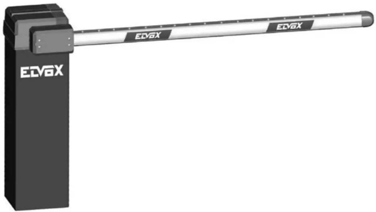
Exterior view of a black ECV6X barrier with a long white bar extending from its side (no text or symbols on the barrier itself)EBRA.3L - EBRA.4L - EBRA.5L
EBRL.S - EBRL.T
EBRM.L
Mozzo e aste con illuminazione a LED per barriere FRAGMA 4A e FRAGMA 6A
Hub and booms with LED lights for FRAGMA 4A and FRAGMA 6A barriers
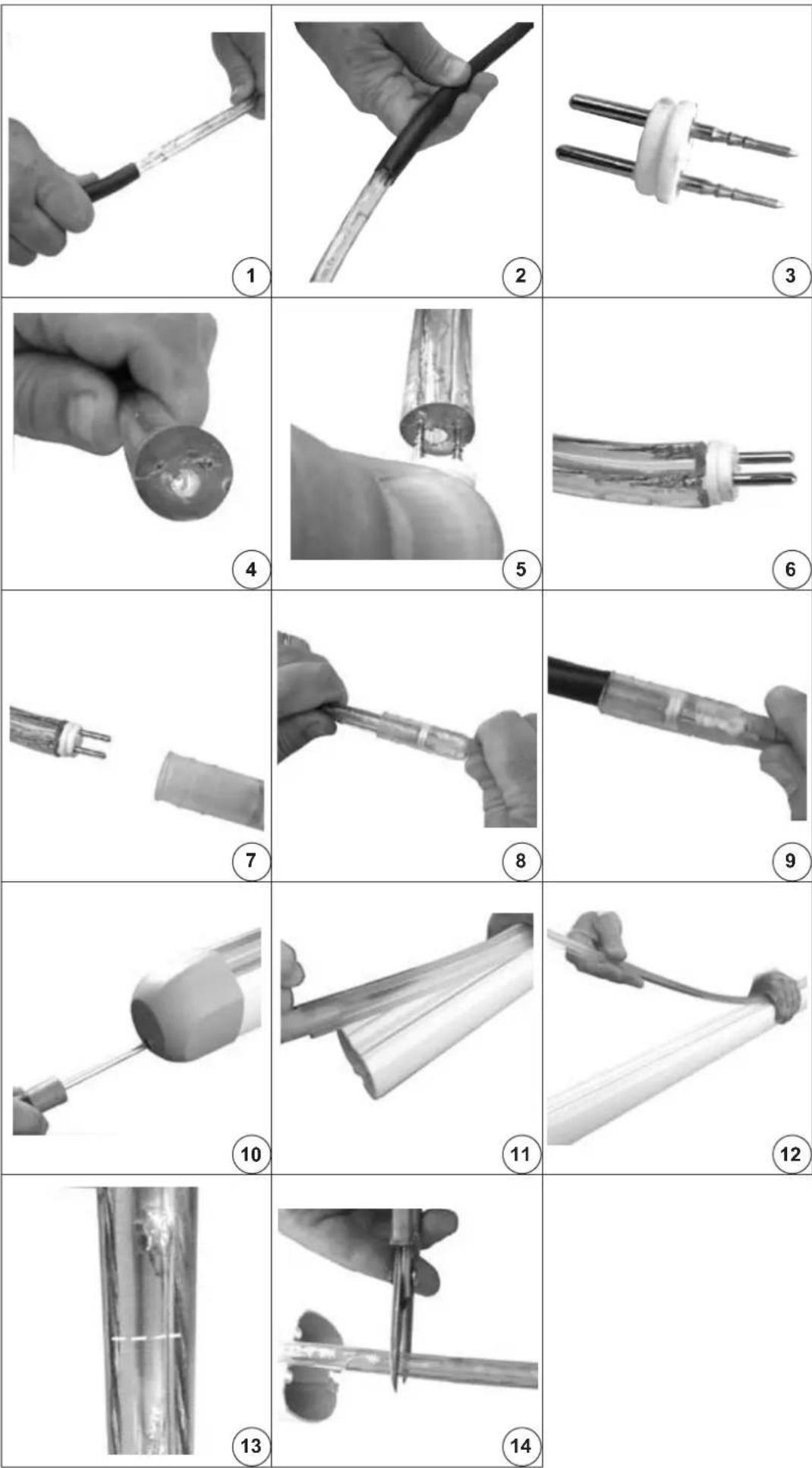
1-2) Inserire la guaina nera ∅ 14 mm sul tubo LED
3) Prendere il connettore maschio in dotazione
1-2) Insert the black 14 mm ∅ sheath onto the LED tube
3) Have the supplied male connector ready
4-5) Inserire con forza il connettore nel tubo LED in riferimento ai 2 conduttori di alimentazione
6) Dopo averlo inserito controllare che il diametro del connettore maschio corrisponda al diametro del tubo LED
4-5) Insert the connector firmly into the LED tube in relation to the 2 LED power supply conductors
6) Once inserted, check that the diameter of the male connector matches the diameter of the LED tube.
7-8) Inserire il tubo LED con connettore maschio nel connettore femmina con cavo di alimentazione in dotazione
9) Avvicinate la guaina ∅ 14 mm al connettore
7-8) Insert the LED tube with male connector into the female connector using the supplied power cable
9) Move the 14 mm ∅ sheath closer to the connector
10) Togliere il tappo anteriore asta utilizzando un cacciavite a croce.
11-12) Togliere completamente la copertura led arancione sollevandola dal profilo dell'asta iniziando dal lato del tappo anteriore.
10) Remove the front cap from the boom using a Phillips screwdriver.
11-12) Remove completely the orange LED cover by lifting it from the beam profile starting from the front cap end.
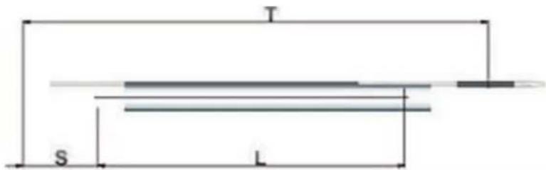
13-14) Tagliate il tubo led lungo il tratteggio alla quota indicata in tabella.
13-14) Cut the LED tube along the dashed line, as indicated in the table.
natural_image
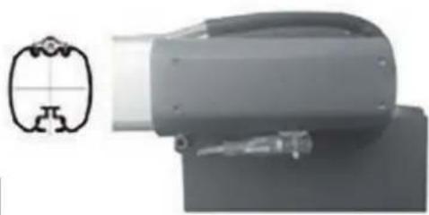
Close-up of a mechanical device with a small inset diagram showing cross-sectional view (no text or symbols)| L (mm) T (mm) S (mm) | ||
| 3154 3545 196 | ||
| 4154 4585 216 | ||
| 5154 5585 236 |
natural_image
Close-up of hands holding a small object, possibly a tool or device, with no visible text or symbols.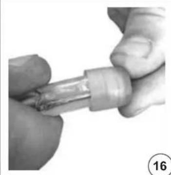
natural_image
Close-up of hands holding a small cylindrical object with a damaged internal structure (no visible text or symbols)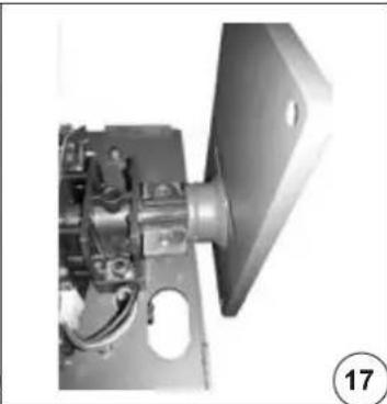
natural_image
Close-up of a mechanical assembly with visible components and a numbered label (17) in the corner, no readable text or symbols present.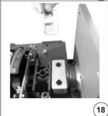
natural_image
Close-up of a mechanical assembly with a tool inserted, showing components like a bracket and screwdriver (no visible text or symbols)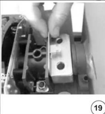
natural_image
Close-up of hands installing or adjusting a mechanical component with a metal bracket (no visible text or symbols)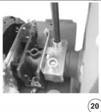
natural_image
Close-up of mechanical components with no visible text or symbols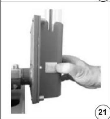
natural_image
Hand holding a mechanical component with a button, no visible text or symbols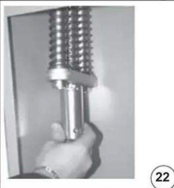
natural_image
Close-up of a hand holding a metallic mechanical component, possibly a tool or spring, against a plain background (no text or symbols visible)
natural_image
Completely blank white image with no visible content, text, or symbols.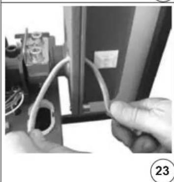
natural_image
Close-up of hands holding a coiled cable or wire attached to a device (no visible text or symbols)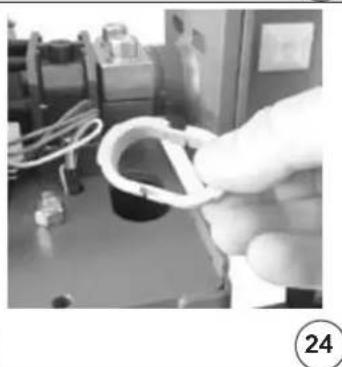
natural_image
Close-up of a gloved hand holding a white plastic ring, with industrial equipment in the background (no visible text or symbols)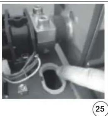
natural_image
Close-up of a mechanical component with wires and a hand pointing to a dark part, no visible text or symbols15-16) Inserire il tappo terminale sul- la punta del tubo LED
17) Inserire il mozzo nell'albero di traino.
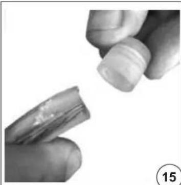
15-16) Insert the end cap onto the end of the LED tube
17) Insert the hub into the drive shaft
18-20) Applicare il cavallotto con la piastrina di tenuta cavo LED
18-20) Apply the shaft clamp with the LED cable retaining plate
21) Fissare il supporto asta al mozzo. Inserire il profilo dell'asta e serrare le viti di fissaggio del supporto. Applicare in riferimento all'asola passacavo nella parte centrale inferiore del mozzo la fascetta adesiva di ritenuta cavo.
22) Inserire le molle di bilancia- mento e avvitare le ghiere per regolare la tensione come in- dicato nel manuale.
21) Anchor the boom support to the hub. Insert the boom tighten the fixing screws. In correspondence to the fairlead slot, apply in the middle-lower part of the boom support the adhesive wire tie mount.
22) Insert the balancing springs and operate the ring nuts to adjust the tension as indicated in the manual.
23) Inserite ora il cavo nell'asola presente sul mozzo.
24-25) Inserire nel foro passaggio cavi la protezione plastica per evitare l'usura dei cavi stessi.
23) Run the cable into the slot on the hub.
24-25) Insert the plastic protection into the slot to prevent the cable from wearing out.
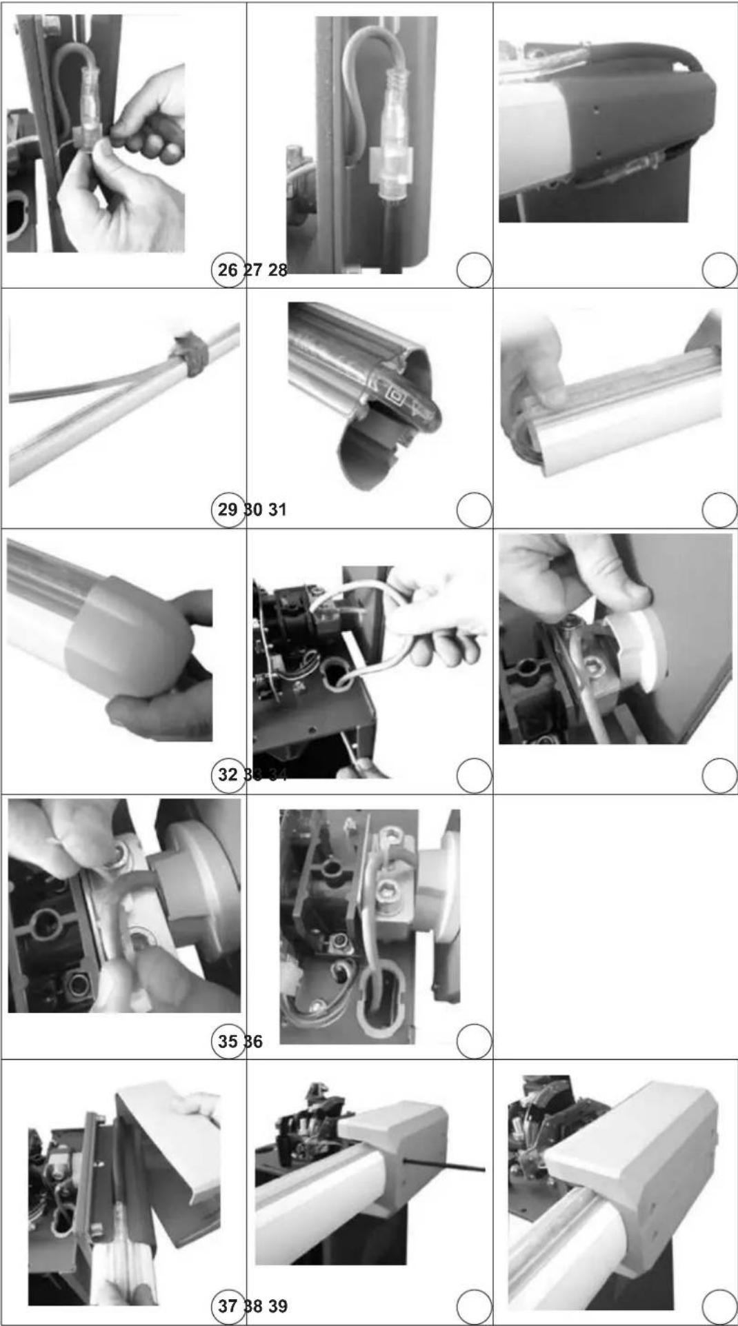
26-27) Fissare, con la fascetta in dotazione, il connettore femmina con il tubo LED inserito, al fissa tubo precedentemente incollato.
28) Sbloccare la barriera, abbassare l'asta e avvolgere il tubo LED attorno al mozzo
26-27) Use the supplied wire tie to fasten the female connector to the LED tube, use the supplied wire tie mount to lock the wire tie in place.
28) Release the barrier and lower the boom, then wrap the LED tube around the hub.
29) Appoggiate il tubo LED nell'apposita sede sull'asta facendolo sporgere della quota S indicata in tabella e bloccatelo con la protezione LED arancio.
30-31) In punta all'asta ripiegate il tubo LED all'interno del profilo.
29) Position the LED tube in its seat on the boom, making it stick out beyond level S indicated in the table and lock it with the orange LED protection.
30-31) At the end of the boom, fold the LED tube within the profile.
32) Applicate il tappo in punta all'asta e fissatelo con l'apposita vite.
33) Inserire il cavo di alimentazione nel foro come da immagine.
34) Applicare ad incastro il blocca cavi come da immagine.
32) Apply the cap at the boom end and fasten it with the corresponding screw.
33) Insert the power cable into the slot, as shown in the figure
34) Apply the cable lock as shown in the figure.
35-36) Fissare il cavo di alimentazione con la fascetta in dotazione nel punto indicato nelle figure
35-36) Fasten the power cable with the supplied wire tie to the point shown in the pictures
37-39) Montare il coperchio del mozzo avvitando le 4 viti in dotazione con una chiave a brugola da 5 mm.
37-39) Assemble the hub cover by tightening the 4 supplied screws with an Allen wrench size 5 mm.
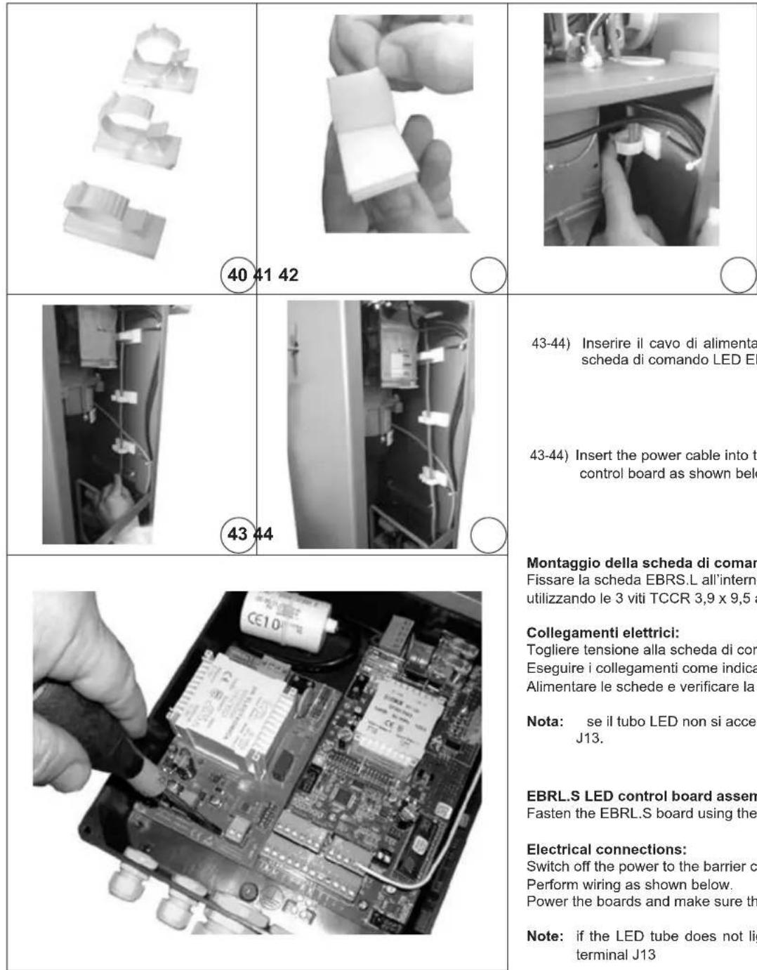
40) Prendere gli anelli adesivi di tenuta cavi.
41-42) Rimuovete la pellicola e applicare gli adesivi all'interno del cassone della barriera come indicato in figura.
40) Have the adhesive rings for cable fastening ready.
41-42) Remove the film and appl: stick them inside the barrier case as shown in the picture.
43-44) Inserire il cavo di alimentazione negli anelli e collegatelo poi alla scheda di comando LED EBRL.S come indicato qui di seguito.
43-44) Insert the power cable into the rings and plug it to the EBRL.S LED control board as shown below.
Montaggio della scheda di comando LED EBRS.L:
Fissare la scheda EBRS.L all'interno del contenitore scheda della barriera utilizzando le 3 viti TCCR 3,9 x 9,5 a corredo.
Collegamenti elettrici:
Togliere tensione alla scheda di comando della barriera (RS15).
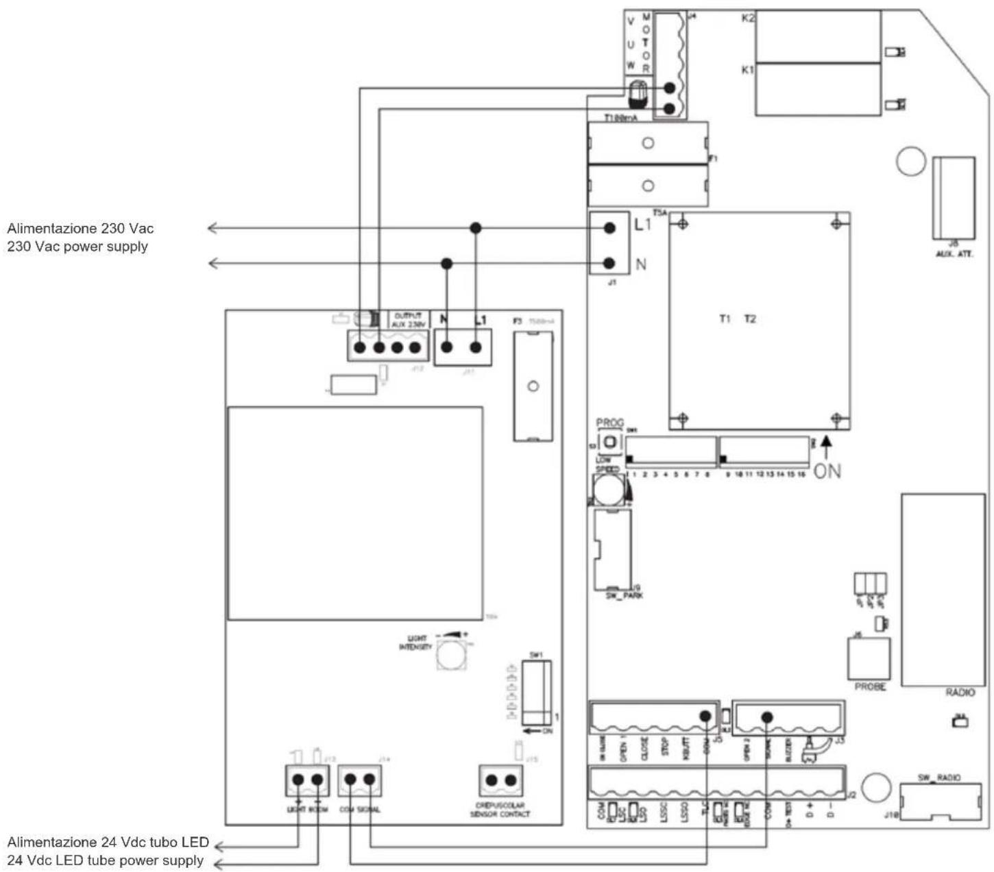
Eseguire i collegamenti come indicato qui di seguito.
Alimentare le schede e verificare la corretta funzionalità delle opzioni scelte.
Nota: se il tubo LED non si accende, invertire i fili connessi nel morsetto J13.
EBRL.S LED control board assembly:
Fasten the EBRL.S board using the 3 supplied 3,9 x 9,5 TCCR screws.
Electrical connections:
Switch off the power to the barrier control board (RS15)
Perform wiring as shown below.
Power the boards and make sure the chosen options function properly.
Note: if the LED tube does not light up, reverse the wires connected to terminal J13
| Serigrafia scheda Tipo Descrizione | ||
| LIGHT INTENSITY Trimmer Regolazione luminosità dei LED | ||
| OUTPUT AUX 230V Morsetto Alimentazione ausiliaria 230Vac50-60 Hz per sensore crepuscolare | ||
| SW1 Banco Dip | Switch | Dip switch per selezione opzioni |
| N - L1 Morsetto | Collegamento | alimentazione 230Vac 50+60 Hz |
 | Morsetto Da collegare all'uscita lampeggiatore della scheda RS15. Per accendere il tubo LED durante il funzionamento della barriera | |
| LIGHT BOOM Morsetto | Collegamento tubo LED 24 Vdc | |
| COM-SIGNAL Morsetto | Collegamento alla scheda RS15per accensione tubo LED solo a barriera chiusa | |
| CREPUSCULAR CONTACT | Morsetto Collegamento contatto pulitoN.O. sensore crepuscolare | |
| Print-out on board Type Description | ||
| LIGHT INTENSITY Trimmer LED intensity adjustment | ||
| OUTPUT AUX 230V | Terminal block | 230 Vac 50÷60 Hz auxiliary power supply for light sensor |
| SW1 | Dip Switch block | Configuration Dip switches |
| N - L1 | Terminal block | 230 Vac 50÷60 Hz power supply connection |
 | Terminal block | To be connected to the RS15 control board flashing light output (to feed the LED tube during barrier movement) |
| LIGHT BOOM | Terminal block | 24 Vdc LED tube power supply |
| COM-SIGNAL | Terminal block | Connection to the RS15 board for lighting up the LED tube only with the barrier closed |
| CREPUSCULAR CONTACT | Terminal block | N.O. dry contact for light sensor |
Tipo di funzionamento luci LED:
1 - Luce sempre accesa fissa
| DIP1 DIP2 DIP3 DIP4 DIP5 DIP6 | |||||
| OFF OFF | OFF OFF | OFF OFF | |||
2 - Luce sempre lampeggiante
| DIP1 DIP2 DIP3 DIP4 DIP5 DIP6 Tempo di lampeggio | |||||
| ON OFF OFF | OFF OFF OFF | OFF 0,5 s ON - 0,5 s | OFF | ||
| ON OFF ON | OFF OFF OFF 1 | s ON - 1 | s OFF | ||
| ON OFF ON | ON OFF OFF 2 | s ON - 1 | s OFF | ||
| ON OFF OFF | ON OFF OFF 0,2 s ON - 0,2 s OFF | ||||
3 - Luce accesa fissa a barriera in movimento
Nota: è obbligatorio collegare i morsetti lampeggiante della scheda RS15 e della scheda EBRS.L
| DIP1 DIP2 DIP3 DIP4 DIP5 DIP6 | |||||
| ON ON | OFF OFF | OFF OFF | |||
4 - Luce lampeggiante a barriera in movimento
Nota: è obbligatorio collegare i morsetti lampeggiante della scheda RS15 e della scheda EBRS.L
| DIP1 | DIP2 | DIP3 | DIP4 | DIP5 | DIP6 | Tempo di lampeggio |
| OFF | ON | OFF | OFF | OFF | 0,5 s ON | - 0,5 s OFF |
| OFF | ON | ON | OFF | OFF | 1 s ON | - 1s OFF |
| OFF | ON | ON | ON | OFF | 2 s ON | - 1 s OFF |
| OFF | ON | OFF | ON | OFF | 0,2 s ON | - 0,2 s OFF |
5 - Luce accesa fissa a barriera ferma e lampeggiante a barriera in movimento
Nota: è obbligatorio collegare i morsetti lampeggiante della scheda RS15 e della scheda EBRS.L
| DIP1 | DIP2 | DIP3 | DIP4 | DIP5 | DIP6 | Tempo di lampeggio | |
| OFF | OFF | OFF | OFF | OFF | 0,5 s ON - 0,5 s | OFF | |
| OFF | OFF | ON | OFF | OFF | 1 s ON - 1s OFF | ||
| OFF | OFF | ON | ON | OFF | 2 s ON - 1 s OFF | ||
| OFF | OFF | OFF | ON | OFF | 0,2 s ON - 0,2 s OFF | ||
6 - Luce accesa fissa solo a barriera chiusa
Nota: è obbligatorio collegare i morsetti lampeggiante della scheda RS15 e della scheda EBRS.L
| DIP1 DIP2 DIP3 DIP4 DIP5 DIP6 | |||||
| OFF OFF | OFF OFF | OFF ON | |||
7 - Luce lampeggiante solo a barriera in chiusa
Nota: è obbligatorio collegare i morsetti lampeggiante della scheda RS15 e della scheda EBRS.L
| DIP1 | DIP2 | DIP3 | DIP4 | DIP5 | DIP6 | Tempo di lampeggio |
| ON | OFF | OFF | OFF | ON 0, | 5 s ON | - 0,5 s OFF |
| ON | OFF | ON | OFF | ON 1 s | ON - 1s OFF | |
| ON | OFF | ON | ON | ON 2 s | ON - 1 s OFF | |
| ON | OFF | OFF | ON | ON 0,2 s | ON - 0,2 s OFF |
8 - Funzionamento con sensore crepuscolare
Impostare DIP5 = ON
Nota: le funzionalità descritte ai punti 1-2-3-4-5-6-7 saranno funzionanti solo di notte con contatto chiuso del sensore crepuscolare.
Working mode of LED lights:
1 - Solid light always ON
| DIP1 DIP2 DIP3 DIP4 DIP5 DIP6 | |||||
| OFF OFF | OFF OFF | OFF OFF | |||
2 - Blinking light always ON
| DIP1 | DIP2 | DIP3 | DIP4 | DIP5 | DIP6 | Blinking | light time |
| ON | OFF | OFF | OFF | OFF | 0,5 s ON | - 0,5 s | OFF |
| ON | OFF | ON | OFF | OFF 1 | s ON - | 1s OFF | |
| ON | OFF | ON | ON | OFF 2 s | ON - 1 | s OFF | |
| ON | OFF | OFF | ON | OFF 0, | 2 s ON | - 0,2 s | OFF |
3 - Solid light ON when barrier moving
Note: it is mandatory to connect the flashing light outputs of the RS15 and EBRS.L control boards
| DIP1 DIP2 DIP3 DIP4 DIP5 DIP6 | |||||
| ON ON | OFF OFF | OFF OFF | |||
4 - Blinking light ON when barrier moving
Note: it is mandatory to connect the flashing light outputs of the RS15 and EBRS.L control boards
| DIP1 | DIP2 | DIP3 | DIP4 | DIP5 | DIP6 | Blinking | light time |
| OFF | ON | OFF | OFF | OFF | 0,5 s ON | - 0,5 s | OFF |
| OFF | ON | ON | OFF | OFF | 1 s ON - 1s OFF | ||
| OFF | ON | ON | ON | OFF | 2 s ON - 1 s OFF | ||
| OFF | ON | OFF | ON | OFF | 0,2 s ON - 0,2 s OFF |
5 - Solid light ON when barrier not moving and blinking light ON when barrier moving
Note: it is mandatory to connect the flashing light outputs of the RS15 and EBRS.L control boards
| DIP1 | DIP2 | DIP3 | DIP4 | DIP5 | DIP6 | Blinking | light time |
| OFF | OFF | OFF | OFF | OFF | 0,5 s ON | - 0,5 s | OFF |
| OFF | OFF | ON | OFF | OFF 1 | s ON - | 1s OFF | |
| OFF | OFF | ON | ON | OFF 2 | s ON - 1 | s OFF | |
| OFF | OFF | OFF | ON | OFF 0,2 s ON | - 0,2 s | OFF |
6 - Solid light ON only when barrier is closed
Note: it is mandatory to connect the flashing light outputs of the RS15 and EBRS.L control boards
| DIP1 DIP2 DIP3 DIP4 DIP5 DIP6 | ||||
| OFF OFF OFF OFF | OFF ON | |||
7 - Blinking light ON only when barrier is closed
Note: it is mandatory to connect the flashing light outputs of the RS15 and EBRS.L control boards
| DIP1 | DIP2 | DIP3 | DIP4 | DIP5 | DIP6 | Blinking | light time |
| ON | OFF | OFF | OFF | ON | 0,5 | s ON | - 0,5 s OFF |
| ON | OFF | ON | OFF | ON | 1 | s ON - 1 | s OFF |
| ON | OFF | ON | ON | OFF | ON | 2 s ON - 1 | s OFF |
| ON | OFF | OFF | ON | OFF | ON | 0,2 s ON - | 0,2 s OFF |
8 - Light sensor activation
Set DIP5 = ON
Note: the working modes described in paragraphs 1-2-3-4-5-6-7 will be active only at night with the light sensor contact closed.
| Caratteristiche tecniche | |
| Temperatura di funzionamento -10 ÷ +55 °C | |
| Umidità < 95% senza condensazione | |
| Tensione di alimentazione 230 Vac 50/60 Hz | |
| Assorbimento massimo 80 mA con tubo LED da 6 m | |
| Micro interruzioni di rete 100 ms | |
| Carico massimo all'uscita LIGHT BOOM 20 W a 24 Vdc | |
| Technical specifications | |
| Working temperature -10 ÷ +55 °C | |
| Humidity < 95% without condensation | |
| Supply voltage 230 Vac 50/60 Hz | |
| Maximum current draw 80 mA with 6 m LED tube | |
| Interruptions in power supply 100 ms | |
| LIGHT BOOM output maximum load 20 W at 24 Vdc |
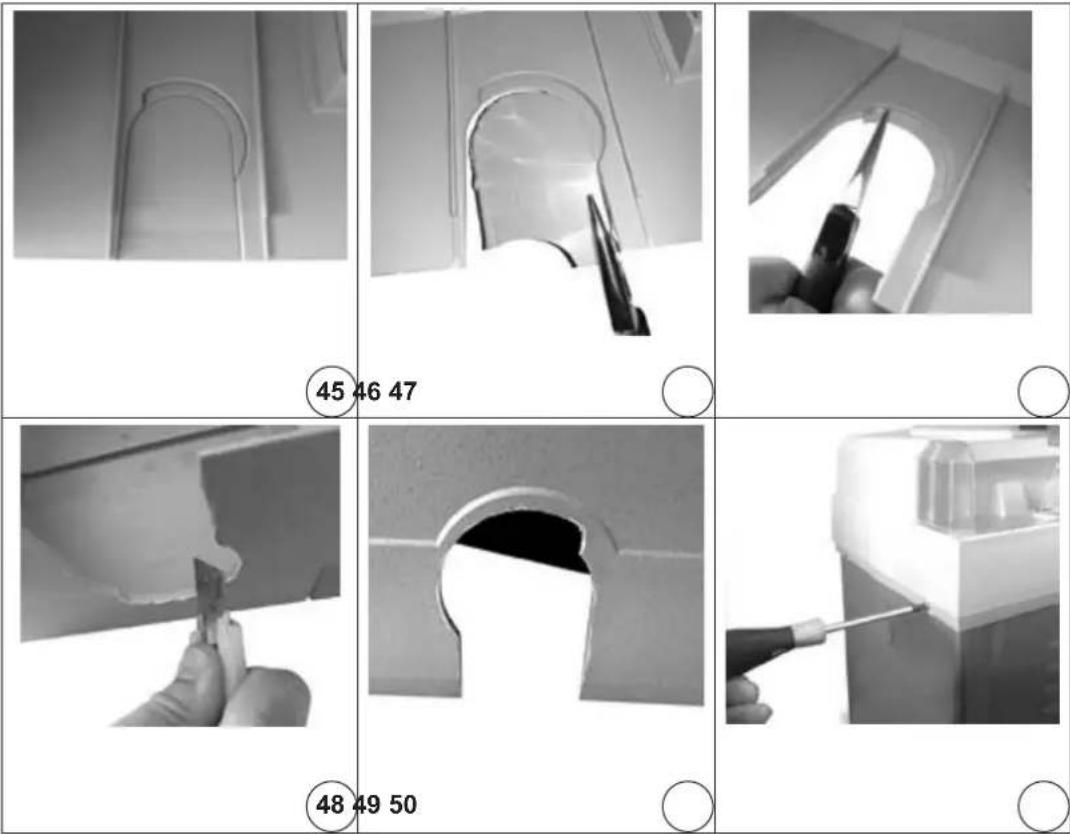
45-47) Rimuovere la palpebra dal carter per consentirne l'inserimento sul cassone della barriera.
45-47) Remove the shaft lid from the top cover to allow mounting the cover on the barrier case.
48-50) Rimuovere con cura tutte le bave per meglio proteggere il cavo di alimentazione del tubo LED durante il movimento dell'asta.
48-50) Carefully remove all the burrs in order to better protect the power cable of the LED tube during the boom movement.
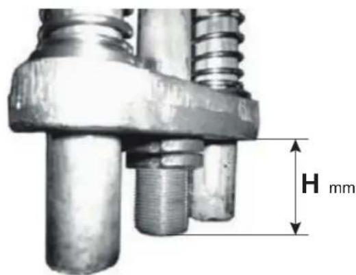
| Lungh. asta | Configurazione asta e accessori | Codici asta e accessori | Molle da installare | Codici molle | Tiraggio H* |
| 3 m | Asta ∅80+tubo LED emozzo EBRA.3L+EBRL.T+EBRM.L 3 x ∅ 4 mm 3xEBRM.4 20 | ||||
| Asta ∅80+tubo LED, mozzo e ap-poggio mobile | EBRA.3L+EBRL.T+EBRM.L+EBRP.M | 2 x ∅ 4,5 mm 2xEBRM.4.5 20 | |||
| Asta ∅80+tubo LED, mozzo e gomma | EBRA.3L+EBRL.T+EBRM.L+EBRG.3 | 2 x ∅ 4,5 mm 2xEBRM.4.5 15 | |||
| Asta ∅80+tubo LED, mozzo e siepe | EBRA.3L+EBRL.T+EBRM.L+EBRS.3 | 2 x ∅ 4,5 mm 2xEBRM.4.5 35 | |||
| Asta ∅80+tubo LED, mozzo, gomma e appoggio mobile | EBRA.3L+EBRL.T+EBRM.L+EBRG.3+EBRP.M | 2 x ∅ 4,5 mm 2xEBRM.4.5 40 | |||
| Asta ∅80+tubo LED, mozzo, siepe e appoggio mobile | EBRA.3L+EBRL.T+EBRM.L+EBRS.3+EBRP.M | 2 x ∅ 4,5 mm+1 x ∅ 5 mm | 2xEBRM.4.5+1xEBRM.5 | 20 | |
| 4 m | Asta ∅80+tubo LED e mozzo EBRA.4L+EBRL.T+EBRM.L 3 x ∅ 4,5 mm 3xEBRM.4.5 20 | ||||
| Asta ∅80+tubo LED, mozzo e ap-poggio mobile | EBRA.4L+EBRL.T+EBRM.L+EBRP.M | 3 x ∅ 4,5 mm 3xEBRM.4.5 30 | |||
| Asta ∅80+tubo LED, mozzo e gomma | EBRA.4L+EBRL.T+EBRM.L+EBRG.4 | 3 x ∅ 4,5 mm 3xEBRM.4.5 45 | |||
| Asta ∅80+tubo LED, mozzo e siepe | EBRA.4L+EBRL.T+EBRM.L+2xEBRS.2 | 3 x ∅ 4,5 mm 3xEBRM.4.5 50 | |||
| Asta ∅80+tubo LED, mozzo, gomma e appoggio mobile | EBRA.4L+EBRL.T+EBRM.L+EBRG.4+EBRP.M | 2 x ∅ 4,5 mm+1 x ∅ 5 mm | 2xEBRM.4.5+1xEBRM.5 | 45 | |
| Asta ∅80+tubo LED, mozzo, siepe e appoggio mobile | EBRA.4L+EBRL.T+EBRM.L+2xEBRS.2+EBRP.M | 1 x ∅ 4,5 mm+2 x ∅ 5 mm | 1xEBRM.4.5+2xEBRM.5 | 45 | |
| 5 m | Asta ∅80+tubo LED e mozzo | EBRA.5L+EBRL.T+EBRM.L | 3 x ∅ 5,5 mm | 3xEBRM.5.5 | 15 |
| Asta ∅80+tubo LED, mozzo e appoggio mobile | EBRA.5L+EBRL.T+EBRM.L+EBRP.M | 3 x ∅ 5,5 mm | 3xEBRM.5.5 30 | ||
| Asta ∅80+tubo LED, mozzo e gomma | EBRA.5L+EBRL.T+EBRM.L+EBRG.5 | 3 x ∅ 5,5 mm | 3xEBRM.5.5 45 | ||
| Asta ∅80+tubo LED, mozzo e siepe | EBRA.5L+EBRL.T+EBRM.L+EBRS.2+EBRS.3 | 3 x ∅ 5,5 mm | 3xEBRM.5.5 55 | ||
| Asta ∅80+tubo LED, mozzo, gomma e appoggio mobile | EBRA.5L+EBRL.T+EBRM.L+EBRG.5+EBRP.M | 3 x ∅ 5,5 mm | 3xEBRM.5.5 50 | ||
| Asta ∅80+tubo LED, mozzo, siepe e appoggio mobile | EBRA.5L+EBRL.T+EBRM.L+EBRS.2+EBRS.3+EBRP.M | 3 x ∅ 5,5 mm | 3xEBRM.5.5 55 |
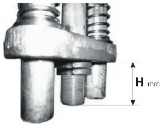
| Boom length | Boom & accessories configuration | Boom & accessories references | Required springs Spring references Spring | tension H* | |
| 3 m | ∅80 boom+LED tube & hub EBRA.3L+EBRL.T+EBRM.L 3 x ∅ 4 mm 3xEBRM.4 20 | ||||
| ∅80 boom+LED tube, hub & moving rest | EBRA.3L+EBRL.T+EBRM.L+EBRP.M | 2 x ∅ 4,5 mm 2xEBRM.4.5 20 | |||
| ∅80 boom+LED tube, hub & rubber edge | EBRA.3L+EBRL.T+EBRM.L+EBRG.3 | 2 x ∅ 4,5 mm 2xEBRM.4.5 15 | |||
| ∅80 boom+LED tube, hub & fence | EBRA.3L+EBRL.T+EBRM.L+EBRS.3 | 2 x ∅ 4,5 mm 2xEBRM.4.5 35 | |||
| ∅80 boom+LED tube, hub, rubber edge & moving rest | EBRA.3L+EBRL.T+EBRM.L+EBRG.3+EBRP.M | 2 x ∅ 4,5 mm 2xEBRM.4.5 40 | |||
| ∅80 boom+LED tube, hub, fence & moving rest | EBRA.3L+EBRL.T+EBRM.L+EBRS.3+EBRP.M | 2 x ∅ 4,5 mm+1 x ∅ 5 mm | 2xEBRM.4.5+1xEBRM.5 | 20 | |
| 4 m | ∅80 boom+LED tube & hub EBRA.4L+EBRL.T+EBRM.L 3 x ∅ 4,5 mm 3xEBRM.4.5 20 | ||||
| ∅80 boom+LED tube, hub & moving rest | EBRA.4L+EBRL.T+EBRM.L+EBRP.M | 3 x ∅ 4,5 mm 3xEBRM.4.5 30 | |||
| ∅80 boom+LED tube, hub & rubber edge | EBRA.4L+EBRL.T+EBRM.L+EBRG.4 | 3 x ∅ 4,5 mm 3xEBRM.4.5 45 | |||
| ∅80 boom+LED tube, hub & fence | EBRA.4L+EBRL.T+EBRM.L+2xEBRS.2 | 3 x ∅ 4,5 mm 3xEBRM.4.5 50 | |||
| ∅80 boom+LED tube, hub, rubber edge & moving rest | EBRA.4L+EBRL.T+EBRM.L+EBRG.4+EBRP.M | 2 x ∅ 4,5 mm+1 x ∅ 5 mm | 2xEBRM.4.5+1xEBRM.5 45 | ||
| ∅80 boom+LED tube, hub, fence & moving rest | EBRA.4L+EBRL.T+EBRM.L+2xEBRS.2+EBRP.M | 1 x ∅ 4,5 mm+2 x ∅ 5 mm | 1xEBRM.4.5+2xEBRM.5 45 | ||
| 5 m | ∅80 boom+LED tube & hub EBR | RA.5L+EBRL.T+EBRM.L 3 x ∅ $,5 mm | 3xEBRM.5.5 | 15 | ||
| ∅80 boom+LED tube, hub & moving rest | EBRA.5L+EBRL.T+EBRM.L+EBRP.M | 3 x ∅ 5,5 mm | 3xEBRM.5.5 | 30 | ||
| ∅80 boom+LED tube, hub & rubber edge | EBRA.5L+EBRL.T+EBRM.L+EBRG.5 | 3 x ∅ 5,5 mm | 3xEBRM.5.5 | 45 | ||
| ∅80 boom+LED tube, hub & fence | EBRA.5L+EBRL.T+EBRM.L+EBRS.2+EBRS.3 | 3 x ∅ 5,5 mm | 3xEBRM.5.5 | 55 | ||
| ∅80 boom+LED tube, hub, rubber edge & moving rest | EBRA.5L+EBRL.T+EBRM.L+EBRG.5+EBRP.M | 3 x ∅ 5,5 mm | 3xEBRM.5.5 | 50 | ||
| Asta ∅80+tubo LED, fence & moving rest | EBRA.5L+EBRL.T+EBRM.L+EBRS.2+EBRS.3+EBRP.M | 3 x ∅ 5,5 mm | 3xEBRM.5.5 | 55 |
DICHIARAZIONE CE DI CONFORMITA'
(Dichiarazione di incorporazione di quasi-macchine allegato IIB Direttiva 2006/42/CE)
No.: ZDT00619.00
Il sottoscritto, rappresentante il seguente costruttore Vimar SpA viale Vicenza, 14 - 36063 Marostica (VI) Italy
dichiara qui di seguito che i prodotti
SCHEDA PER LED PER BARRIERA FRAGMA
Articoll
Marca Rif. per tipo Rif. a cat. Descrizione
Elvox EBRL.S EBRL.S Scheda alimentazione LED barriere FRAGMA 4A/6A
Accessori
Elvox EBRA.3L EBRA.3L Asta LED 3m barriere FRAGMA 4A
Elvox EBRA.4L EBRA.4L Asta LED 4m barriere FRAGMA 4A
Elvox EBRA.5L EBRA.4L Asta LED 5m barriere FRAGMA 4A
risultano in conformità a quanto previsto dalla(e) seguente(i) direttiva(e) comunitaria(e) (comprese tutte le modifiche applicabili) e che sono state applicate tutte le seguenti norme e/o specifiche tecniche
Direttiva Macchine 2006/42/CE EN 13241-1 (2003) + A1 (2011), EN 12453 (2002), EN 12445 (2002)
Direttiva BT 2006/95/CE EN 60335-1 (2012) + A11 (2014)
Direttiva EMC 2004/108/CE EN 55014-1 (2006) + A1 (2009) + A2 (2012), EN 55014-2 (1997) +
A1 (2001) + A2 (2008) + EN 61000-3-2 (2006) + A1 (2009) + A2 (2009)
EN 61000-3-3 (2008), EN 61000-6-1 (2007), EN 61000-6-3 (2007) +
A1 (2011), EN 61000-6-2 (2005), EN 61000-6-4 (2007) + A1 (2011)
Dichiara inoltre che la messa in servizio del prodotto non deve avvenire prima che la macchina finale, in cui deve essere incorporato, non è stata dichiarata conforme, se del caso, alle disposizioni della Direttiva 2006/42/CE
Dichiara che la documentazione tecnica pertinente è stata costituita da Vimar SpA, è stata compilata in conformità all'allegato VIIB della Direttiva 2006/42/CE e che sono stati rispettati i seguenti requisiti essenziali: 1.1.1, 1.1.2, 1.1.3, 1.1.5, 1.1.6, 1.2.1, 1.2.2, 1.2.6, 1.3.1, 1.3.2, 1.3.3, 1.3.4, 1.3.7, 1.3.8, 1.3.9, 1.4.1, 1.4.2, 1.5.1, 1.5.2, 1.5.4, 1.5.5, 1.5.6, 1.5.7, 1.5.8, 1.5.9, 1.6.1, 1.6.2, 1.7.1, 1.7.2, 1.7.3, 1.7.4, 4.1.2.
Si impegna a presentare, in risposta ad una richiesta adeguatamente motivata delle autorità nazionali, tutta la necessaria documentazione giustificativa pertinente al prodotto.
Marostica, 09/10/2015
L'Amministratore Delegato
Nota: Il contenuto di questa dichiarazione corrisponde a quanto dichiarato nell'ultima revisione della dichiarazione ufficiale disponibile prima della stampa di questo manuale. Il presente testo è stato adattato per motivi editoriali. Copia della dichiarazione originale può essere richiesta a Vimar SpA
EC DECLARATION OF CONFORMITY
(Declaration of incorporation of partly completed machinery annex IIB Directive 2006/42/EC)
No.: ZDT00619.00
The undersigned, representing the following manufacturer Vimar SpA viale Vicenza, 14 - 36063 Marostica (VI) Italy
herewith declares that the products
CONTROL UNIT FOR LED LIGHTING CHAINS FOR FRAGMA
Articles
Trade mark Type ref. Cat. ref. Description
Elvox EBRL.S EBRL.S Control unit for booms with LED lighting chains for FRAGMA 4A/6A
Accessories
Elvox EBRA.3L EBRA.3L Boom with LED for FRAGMA 4A, length 3m
Elvox EBRA.4L EBRA.4L Boom with LED for FRAGMA 4A, length 4m
Elvox EBRA.5L EBRA.4L Boom with LED for FRAGMA 4A, length 5m
are in conformity with the provisions of the following EC directive(s) (including all applicable amendments) and that the following standards and/or technical specifications have been applied
Machinery Directive 2006/42/EC EN 13241-1 (2003) + A1 (2011), EN 12453 (2002), EN 12445 (2002)
LV Directive 2006/95/EC EN 60335-1 (2012) + A11 (2014)
EMC Directive 2004/108/EC EN 55014-1 (2006) + A1 (2009) + A2 (2012), EN 55014-2 (1997) +
A1 (2001) + A2 (2008) + EN 61000-3-2 (2006) + A1 (2009) + A2 (2009),
EN 61000-3-3 (2008), EN 61000-6-1 (2007), EN 61000-6-3 (2007) +
A1 (2011), EN 61000-6-2 (2005), EN 61000-6-4 (2007) + A1 (2011)
Further hereby declares that the product must not be put into service until the final machinery into which it is to be incorporated has been declared in conformity with the provisions of Directive 2006/42/EC, where appropriate.
Declares that the relevant technical documentation is compiled by Vimar SpA and in accordance with part B of Annex VII of Directive 2006/42/EC and the following essential requirements of this Directive are applied and fulfilled: 1.1.1, 1.1.2, 1.1.3, 1.1.5, 1.1.6, 1.2.1, 1.2.2, 1.2.6, 1.3.1, 1.3.2, 1.3.3, 1.3.4, 1.3.7, 1.3.8, 1.3.9, 1.4.1, 1.4.2, 1.5.1, 1.5.2, 1.5.4, 1.5.5, 1.5.6, 1.5.7, 1.5.8, 1.5.9, 1.6.1, 1.6.2, 1.7.1, 1.7.2, 1.7.3, 1.7.4, 4.1.2.
I undertake to make available, in response to a reasoned request by the national authorities, any further supporting product documents they require.
Marostica, 09/10/2015
The Managing Director
Note: The contents of this declaration correspond to what declared in the last revision of the official declaration available before printing this manual. The text herein has been re-edited for editorial purposes. A copy of the original declaration can be requested to Vimar SpA
AVVERTENZE PER L'INSTALLATORE
-Leggereattentamenteleavvertenzecontenutenelpresentedocumento in quanto for ni sco no importanti indicazioni ri guar dan ti la sicurezza di instal la zio ne, d'uso e di ma nu ten zio ne.
- Dopo aver tolto l'imballaggio assicurarsi dell'integrità del l'ap pa rec chio. Gli ele men ti dell'imballaggio (sacchetti di pla sti ca, po li sti ro lo espanso, ecc.) non devono essere lasciati alla portata dei bambini in quanto potenziali fonti di pericolo. L'esecuzione dell'impianto deve essere ri spon den te alle nor me CEI vigenti.
- È necessario prevedere a monte dell'alimentazione un appropriato inter rut to re di tipo onnipolare facilmente accessibile con separazione tra i contatti di almeno 3 mm.
- Prima di col le ga re l'apparecchio ac cer tar si che i dati di targa siano rispondenti a quelli della rete di di stri bu zio ne.
- Questo ap pa rec chio dovrà essere de sti na to solo all'uso per il quale è stato espres sa men te concepito, e cioè per sistemi di automazione. Ogni altro uso è da con si de rar si im pro prio e quindi pericoloso. Il costruttore nonpuòessereconsideratoresponsabilepereventualidanniderivanti dausiimpropri,erroneiedirragionevoli.
-Primadieffettuarequalsiasioperazionedipuliziaodimanutenzione, disinserire l'apparecchio dalla rete di ali men ta zio ne elettrica, spe gnen do l'interruttore del l'im pian to.
- In caso di guasto e/o di cattivo fun zio na men to del l'ap pa rec chio, togliere l'ali men ta zio ne me dian te l'interruttore e non ma no met ter lo. Per l'eventuale riparazione rivolgersi solamente ad un centro di assistenza tecnica autorizzato dal costruttore. Il mancato ri spet to di quanto so pra può compro met te re la si cu rez za del l'ap pa rec chio.
- Non ostru i re le aperture o fessure di ven ti la zio ne o di smaltimento calore e non esporre l'apparecchio a stillicidio o spruzzi d'acqua.
- L'installatore deve as si cu rar si che le in for ma zio ni per l'uten te siano presentisugliapparecchiderivati.
- Tutti gli apparecchi costituenti l'impianto devono essere de sti na ti esclusi va men te all'uso per cui sono stati con ce pi ti.
- ATTENZIONE: per evitare di ferirsi, questo apparecchio deve essere assicurato alla parete secondo le istruzioni di installazione.
- Questo do cu men to dovrà sem pre ri ma ne re allegato alla do cu men tazio ne dell'impianto.

Direttiva 2002/96/CE (WEEE, RAEE).
Il simbolo del cestino barrato riportato sull'apparecchio indica che il prodotto, alla fine della propria vita utile, dovendo essere trattato separatamente dai rifiuti domestici, deve essere conferito in un cen-
tro di raccolta differenziata per apparecchiature elettriche ed elettroniche oppure riconsegnato al rivenditore al momento dell'acquisto di una nuova apparecchiatura equivalente.
L'utente è responsabile del conferimento dell'apparecchio a fine vita alle appropriate strutture di raccolta. L'adeguata raccolta differenziata per l'avvio successivo dell'apparecchio dismesso al riciclaggio, al trattamento e allo smaltimento ambientalmente compatibile contribuisce ad evitare possibili effetti negativi sull'ambiente e sulla salute e favorisce il riciclo dei materiali di cui è composto il prodotto. Per informazioni più dettagliate inerenti i sistemi di raccolta disponibili, rivolgersi al servizio locale di smaltimento rifiuti, o al negozio in cui è stato effettuato l'acquisto.
Rischi legati alle sostanze considerate pericolose (WEEE).
Secondo la nuova Direttiva WEEE sostanze che da tempo sono utilizzate comunemente su apparecchi elettrici ed elettronici sono considerate sostanze pericolose per le persone e l'ambiente. L'adeguata raccolta differenziata per l'avvio successivo dell'apparecchio dismesso al riciclaggio, al trattamento e allo smaltimento ambientalmente compatibile contribuisce ad evitare possibili effetti negativi sull'ambiente e sulla salute e favorisce il riciclo dei materiali di cui è composto il prodotto.

Il prodotto è conforme alla direttiva europea 2004/108/CE e successive.
SAFETY INSTRUCTIONS FOR INSTALLERS
- Carefully read the instructions on this leaflet: they give important information on the safety, use and maintenance of the installation.
- After removing the packing, check the integrity of the set. Packing components (plastic bags, expanded polystyrene etc.) are dangerous for children. Installation must be carried out according to national safety regulations.
- It is convenient to fit close to the supply voltage source a proper omini-polar type switch with 3 mm separation (minimum) between contacts.
- Before connecting the set, ensure that the data on the label correspond to those of the mains.
- Use this set only for the purposes designed, i.e. for automatic gate systems. Any other use may be dangerous. The manufacturer is not responsible for damage caused by improper, erroneous or irrational use.
- Before cleaning or maintenance, disconnect the set.
- In case of failure or faulty operation, disconnect the set and do not open it.
- For repairs apply only to the technical assistance centre authorized by the manufacturer.
- Safety may be compromised if these instructions are disregarded.
- Do not obstruct opening of ventilation or heat exit slots and expose the set to dripping or sprinkling of water.
- Installers must ensure that manuals with the above instructions are left on connected units after installation, for users' information.
- All items must only be used for the purposes designed.
- WARNING: to avoid the possibility of hurting yourself, this unit must be fixed to the wall according to the installation instructions.
- This leaflet must always be enclosed with the equipment.

Directive 2002/96/EC (WEEE)
The crossed-out wheelie bin symbol marked on the product indicates that at the end of its useful life, the product must be handled separately from household refuse and must therefore be assigned
to a differentiated collection centre for electrical and electronic equipment or returned to the dealer upon purchase of a new, equivalent item of equipment.
The user is responsible for assigning the equipment, at the end of its life, to the appropriate collection facilities.
Suitable differentiated collection, for the purpose of subsequent recycling of decommissioned equipment and environmentally compatible treatment and disposal, helps prevent potential negative effects on health and the environment and promotes the recycling of the materials of which the product is made. For further details regarding the collection systems available, contact your local waste disposal service or the shop from which the equipment was purchased.
Risks connected to substances considered as dangerous (WEEE).
According to the WEEE Directive, substances since long usually used on electric and electronic appliances are considered dangerous for people and the environment. The adequate differentiated collection for the subsequent dispatch of the appliance for the recycling, treatment and dismantling (compatible with the environment) help to avoid possible negative effects on the environment and health and promote the recycling of material with which the product is compound.

Product is according to EC Directive 2004/108/EC and following norms.



- Manuale per il collegamento e l'uso Installation and operation manual
- Montaggio della scheda di comando LED EBRS.L:
- Collegamenti elettrici:
- EBRL.S LED control board assembly:
- Electrical connections:
- DICHIARAZIONE CE DI CONFORMITA'
- SCHEDA PER LED PER BARRIERA FRAGMA
- EC DECLARATION OF CONFORMITY
- CONTROL UNIT FOR LED LIGHTING CHAINS FOR FRAGMA
- AVVERTENZE PER L'INSTALLATORE
- Direttiva 2002/96/CE (WEEE, RAEE).
- Rischi legati alle sostanze considerate pericolose (WEEE).
- SAFETY INSTRUCTIONS FOR INSTALLERS
- Directive 2002/96/EC (WEEE)
- Risks connected to substances considered as dangerous (WEEE).
Marke : Vimar
Modell : ELVOX EBRA.5L
Kategorie : Nicht kategorisiert