
AH-4 - Radio ICOM - Kostenlose Bedienungsanleitung
Finden Sie kostenlos die Bedienungsanleitung des Geräts AH-4 ICOM als PDF.


| Produkttyp | HF + 50 MHz Automatischer Antennenabstimmer |
| Marke | ICOM |
| Modell | AH-4 |
| Kategorie | Funkzubehör |
| Frequenzbereich | 3,5–54 MHz (mit Antenne >7 m); 7–54 MHz (mit AH-2b) |
| Eingangsimpedanz | 50 Ω |
| Maximale Eingangsleistung | 100 W (SSB, typisch) |
| Abstimmleistung (abgestrahlt) | < 0,3 W |
| Frequenzspeicher | 45 Speicherplätze |
| Gehäuse | Wetterfest (Kunststoff, versiegelt) |
| Stromversorgung | Über Steuerkabel vom Transceiver (13,8 V DC) |
| Gewicht (ca.) | 1,2 kg |
| Lieferumfang | Montageset (U-Bolzen, Halterungen, Scheiben), PL-259 Stecker (2), Steuerkabel (5 m), Koaxialkabel (5 m), Wetterschutzkappe, Gummivulkanisierband |
| Montage | An Antennenmast oder flacher Oberfläche |
| Kompatible Antennen | Lange Drahtantenne ab 7 m Länge oder optionale AH-2b (2,5 m) |
| Optionen | OPC-420 abgeschirmtes Steuerkabel (10 m), AH-2b Antennenelement |
| Sicherheitshinweise | Erdung erforderlich; nie ohne Antenne betreiben; Hochspannung während des Sendens |
| Wartung | Dichtungen prüfen, Kabelanschlüsse wasserdicht machen (Gummivulkanisierband) |
| Reparatur | Ersatzteile über Icom (z. B. OPC-420 Steuerkabel) |
Häufig gestellte Fragen - AH-4 ICOM
Benutzerfragen zu AH-4 ICOM
0 Frage zu diesem Gerät. Beantworten Sie die, die Sie kennen, oder stellen Sie Ihre eigene.
Eine neue Frage zu diesem Gerät stellen
Laden Sie die Anleitung für Ihr Radio kostenlos im PDF-Format! Finden Sie Ihr Handbuch AH-4 - ICOM und nehmen Sie Ihr elektronisches Gerät wieder in die Hand. Auf dieser Seite sind alle Dokumente veröffentlicht, die für die Verwendung Ihres Geräts notwendig sind. AH-4 von der Marke ICOM.
BEDIENUNGSANLEITUNG AH-4 ICOM
Fig.6 MOUNTING EXAMPLES
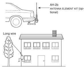
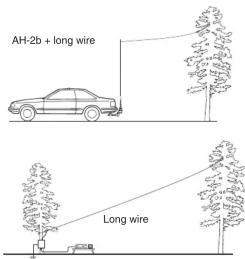
OPERATION
Tuning is required for each frequency. Be sure to retune the antenna before transmitting when you change the frequency— even slightly.
(eg. IC-7000)
Set the desired frequency in an amateur band. ①
• The AH-4 will not operate on frequencies outside
bands
Hold down [TUNER/CALL] for 1 seconds. ②
• " TUR indicator appears while tuning.
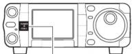
Hold down [TUNER/CALL] for 1 second.
③ " TUNE " indicator stays ON when tuning is complete.
- When the antenna cannot be tuned, "10" indicator blinks,
hand the AH-4 is bypassed and the antenna is directly connected
to the antenna connector on the transceiver.
To manually bypass the AH-4, push [TUNER/CALL]. ④
CALCULATION OF UNDESIRABLE ANTENNA LENGTHS

[EXAMPLE] Antenna lengths to avoid when operating
MH:
Multiple 300 1
of 1 / 2 = 29 × 2 × (1, 2, 3...) = 5.2, 10.3, 15.5 m
29.00
SPECIFICATIONS AND OPTIONS
◇ Specifications
- Frequency range
3.5–54 MHz (with an antenna longer
than 7 m; 23 ft)
7–54 MHz (with the AH-2b)
• Maximum input power
- Input impedance
• Tuning power required
- Rated voltage
[Non-Text]
- Usable temperature range
• VSWR
• Weight (approximately)
- Dimensions
(projections not included)
(1) 2
(1) 12 (2) 13 (3)
All specifications are subject to change without notice or obligation.
◇ Options
• OPC-420 SHIELDED CONTROL CABLE
Shielded control cable helps protect the transceiver from RF feed-
back and extends separation between tuner and transceiver up to
10 m. (cable length 10 m; 32.8 ft)
• AH-2b ANTENNA ELEMENT
A 2.5 m long antenna element for mobile operation with AH-4. Fre-
quency coverage: 7–54 MHz with the AH-4.

INSTRUCTIONS
HF + 50 MHz AUTOMATIC ANTENNA TUNER
AH-4
Thank you for purchasing the AH-4 HF + 50 MHz AU-
TOMATIC ANTENNA TUNER. The AH-4 matches your
transceiver to an antenna more than 7 m/23 ft long (3.5–54 MHz), or the optional AH-2b (7–54 MHz).
Please read these instructions thoroughly before installing and operating the AH-4.
DANGER!
Ground terminal
○ WIDE TUNING RANGE
The AH-4 provides reliable matching from 3.5 MHz to 54 MHz when using at least a 7 m (23 ft) antenna; or 7 MHz to 54 MHz when using the AH-2b ANTENNA ELEMENT.
○ AUTOMATIC DIGITAL CONTROL TUNING
The built-in 8-bit microprocessor chooses the lowest SWR using more than 1,040,000 different LC (coil/capacitor) combinations.
○ 45 FREQUENCY MEMORIES FOR FAST TUNING
The LC combinations of 45 previously-used frequencies are automatically memorized. Once a frequency is memorized, the AH-4 tunes on that frequency in less than 1 second. Note that the AH-4 does not memorize a frequency which is normally tuned within 2.5 seconds. Memories are retained only when the power is on.
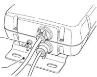
△NEVER operate this tuner without a solid ground. Always connect the ground wire to the ground terminal. DO NOT use the mounting plate as a ground terminal.
NEVER transmit or tune without an antenna connected. Failure to use an antenna will damage the tuner.
△HIGH VOLTAGE! NEVER touch the antenna while transmitting or tuning. Place the antenna in a position where you are sure it will not be touched.
FEATURES
○ WEATHERPROOF DESIGN
The AH-4's tightly sealed plastic case allows convenient mounting virtually anywhere. The AH-4 can be mounted outdoors under your antenna.
○ 0.3 W RADIATED POWER
Radiated power during tuning is less than 0.3 W, minimizing interference to other stations.
NOTE:
The AH-4 can be used with most of Icom HF transceiver, which covers HF through 50 MHz bands.
However, the IC-706 and IC-736 can only be tuned in the 3.5–30 MHz range.
SUPPLIED ACCESSORIES
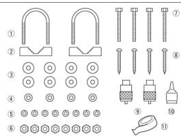
① U-bolts 2
② O-bolt brackets 2 ③ Flat washers (MC large) 9
⑤ Flat washers (MO large) .... 8 ④ Flat washers (MO small) .... 4
④ Flat washers (MO small)....4 ⑤ Spring washers (MG)....8
⑥ Nuts (M6) 8
⑦ Hex head bolts (M6 × 50) 4
⑧ Self-tapping screws (A0 6 × 30) 4
⑨ PL-259 connectors 2
⑩ Weatherproof cap 1
⑪ Rubber vulcanizing tape 1
Control cable* (5 m; 16.4 ft) 1
Coaxial cable* (5D-2V: 5 m; 16.4 ft)....1
*Not shown in the illustration to the left.
Icom Inc.
1-1-32 Kamiminami, Hirano-ku, Osaka 547-0003 Japan
Count on us!
A-8295H-1EX-② Printed in Japan
© 1997–2012 Icom Inc
INSTALLATION
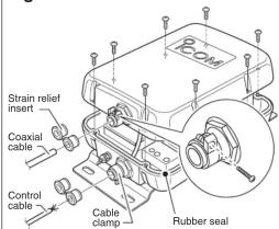
NOTE: After inserting the coaxial cable through the waterproof cap and into the AH-4 top cover, solder the PL-259 connector to the coaxial cable.
Remove the top cover (Fig. 1). ①
Install the control cable and coaxial cable (Fig. 1). ②
Connect and solder the PL-259 connector to the coaxial ③
cable (Fig. 3).
Connect the control cable to the AH-4 (Fig. 2-1). ④
Connect the GND cable to the AH-4 (Fig. 4). ⑤
Replace the top cover. ⑥
Mount the AH-4 in the desired location; on an antenna ⑦
pole, in your vehicle's trunk, and so on. (Fig. 5).
Connect an antenna to the AH-4 (Fig. 6). ⑧
Connect the control cable and the coaxial cable to the ⑨
transceiver.
Fig. 1 COVER REMOVAL AND CABLE INSTALLATION
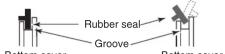
About the rubber seal
Correct position
Incorrect position
NOTE:
- Make sure the cable clamps are well tightened with the screws, oth-
erwise the waterproof protection may not be guaranteed.
• We recommend that you also wrap rubber vulcanizing tape or electri-
cal tape over the cable clamps for better waterproofing.
NOTE:
When attaching the tuner cover, make sure dust or other material does
not adhere to the rubber seal. If dust or other material is on the seal
when attaching, waterproof protection may not be guaranteed.
Make sure the rubber seal is properly seated into the groove.
Fig. 2-1 CABLE CONNECTIONS (eg. IC-7000)
NOTE: Connect the coaxial cable to the appropriate antenna
connector if the transceiver has more than one.
See your transceiver's instruction manual for details.
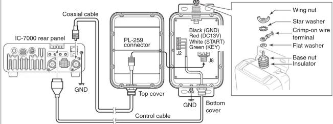
See the Fig. 2-2 as shown to the right above.
Put the flat washer, crimp-on wire terminal, star washer and then wing nut on the base bolt. Then, tighten the wing nut.
- Before you tighten the wing nut, make sure the base nut is firmly tightened.
• After you tighten the wing nut, carefully bend the wire terminal up so the wire lines up with the insulator.
② Place the weatherproof cap over as much of the insulator as possible.
③ Wrap the insulator with the rubber vulcanizing tape, starting at its bottom, then the cap, and finally the antenna wire.
This will help prevent water seepage.
- Also, you may wrap electrical tape over the wrapped rubber vulcanizing tape for better waterproofing.
Fig. 2-2 Waterproofing the antenna connection


Carefully bend this part up, AFTER you tighten the wing nut.


Pull the tape to slightly stretch it as you wrap firmly around the weatherproof cap.
Rubber vulcanizing tape
Fig. 3 PL-259 CONNECTOR SOLDERING
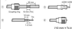
(10 mm ≈ 3/8 in)
① Slide the coupling ring over the coaxial cable. Carefully cut only the cable jacket, and pull it out to reveal 10 mm (0.4 in) of braid.
• Tin the exposed braid and then pull the jacket out.
Strip the cable, as shown to the left. Tin the entire length of the exposed center conductor.
③Slide the connector body over the cable and solder, as shown to the left.
⑧crew the coupling ring onto the connector body.
Fig. 4 GROUND CONNECTIONS
The transceiver and antenna tuner must have an adequate ground connection. Otherwise, the overall efficiency of the transceiver and antenna tuner installation will be reduced. Interference, RF feedback and electrical shocks from other equipment could also occur.
For best results, use the heaviest gauge wire or strap available, and make the connection as short as possible. (see the illustration to the right)
- A long wire connected to the GND terminal as a counterpoise is also acceptable.
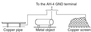
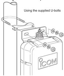
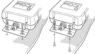
Fig. 5 MOUNTING THE AH-4
- Mounting on an antenna pole
- Mounting on a flat location
Using self-tapping screws
Using nuts and bolts
natural_image
Two identical line drawings of a digital meter device with base, no text or symbols present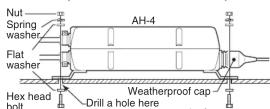
(diameter: 6.6–7 mm; ¼–⁹/32 inches)

- OPERATION
- SPECIFICATIONS AND OPTIONS
- DANGER!
- FEATURES
- SUPPLIED ACCESSORIES
- INSTALLATION
- Fig. 1 COVER REMOVAL AND CABLE INSTALLATION
- NOTE:
- Fig. 2-1 CABLE CONNECTIONS (eg. IC-7000)
- See the Fig. 2-2 as shown to the right above.
- Fig. 2-2 Waterproofing the antenna connection
- Fig. 3 PL-259 CONNECTOR SOLDERING
- Fig. 4 GROUND CONNECTIONS
- Fig. 5 MOUNTING THE AH-4
Marke : ICOM
Modell : AH-4
Kategorie : Radio