
ICM600 - Walkie-Talkie ICOM - Kostenlose Bedienungsanleitung
Finden Sie kostenlos die Bedienungsanleitung des Geräts ICM600 ICOM als PDF.


| Produkttyp | HF-Marine-Transceiver (Marinefunkgerät) |
| Marke | ICOM |
| Modell | ICM600 |
| Frequenzbereich (Empfang) | 0,5000 – 30,0000 MHz (durchgehend) |
| Frequenzbereich (Senden) | 1,6000 – 1,9999 MHz, 2,0000 – 2,9999 MHz, 4,0000 – 4,9999 MHz, 6,0000 – 6,9999 MHz, 8,0000 – 8,9999 MHz, 12,0000 – 13,9999 MHz, 16,0000 – 17,9999 MHz, 18,0000 – 19,9999 MHz, 22,0000 – 22,9999 MHz |
| Betriebsarten | J3E (USB), H3E, R3E |
| Sendeleistung (PEP) | 150 W (hoch), 60 W (niedrig) |
| Stromversorgung | 13,6 V DC ±15 % (negative Masse), mind. 30 A |
| Stromaufnahme (Empfang) | 3 A bei maximaler Audioausgabe |
| Stromaufnahme (Senden) | 30 A bei maximaler HF-Ausgangsleistung |
| Frequenzstabilität | ±20 Hz (-10 °C bis +60 °C) |
| Abmessungen (B × H × T) | 287 × 90 × 233 mm (ohne Vorsprünge) |
| Gewicht | ca. 6,75 kg |
| Antennenimpedanz | 50 Ω (unsymmetrisch) |
| Memory-Kanäle | 99 benutzerprogrammierbare, 314 ITU-Kanäle |
| Notruffrequenz | 2182 kHz mit nur einem Tastendruck |
| Alarmsignal | 2-Ton-Alarm auf 2182 kHz, ca. 50 Sek. |
| Klarheit (Clarity) | ±150 Hz in 10-Hz-Schritten |
| Rauschsperre | Audio-aktivierte Rauschsperre (Squelch) |
| Rauschunterdrückung | Noise Blanker |
| AGC | Automatische Verstärkungsregelung (ein-/ausschaltbar) |
| RF-Verstärkung | 7-stufig einstellbar |
| Spritzwasserschutz | Spritzwassergeschützte Frontplatte |
| Hintergrundbeleuchtung | Tastatur und Display (ein-/ausschaltbar) |
| Sicherheitshinweise | Niemals an Wechselstrom oder >16 V DC anschließen; Gerät erden; Mikrofon und Lautsprecher mind. 1 m vom Magnetkompass entfernt halten |
| Reinigung | Mit trockenem, weichem Tuch; keine chemischen Reinigungsmittel |
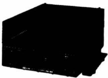
| Zubehör (optional) | AT-120E Antennentuner, MN-100/-100L Antennenanpassgerät, PS-60 Netzteil, PS-66 DC-DC-Wandler, HS-50 Handapparat, OPC-302/303 ACC-Kabel |
Häufig gestellte Fragen - ICM600 ICOM
Benutzerfragen zu ICM600 ICOM
0 Frage zu diesem Gerät. Beantworten Sie die, die Sie kennen, oder stellen Sie Ihre eigene.
Eine neue Frage zu diesem Gerät stellen
Laden Sie die Anleitung für Ihr Walkie-Talkie kostenlos im PDF-Format! Finden Sie Ihr Handbuch ICM600 - ICOM und nehmen Sie Ihr elektronisches Gerät wieder in die Hand. Auf dieser Seite sind alle Dokumente veröffentlicht, die für die Verwendung Ihres Geräts notwendig sind. ICM600 von der Marke ICOM.
BEDIENUNGSANLEITUNG ICM600 ICOM
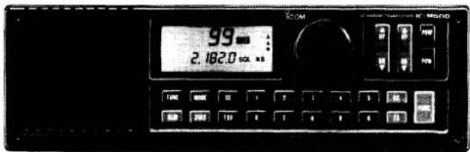
HF MARINE TRANSCEIVER (EUROPE VERSION)
IC-M600
FOREWORD
Thank you for purchasing the IC-M600 HF MARINE TRANSCEIVER. The IC-M600 is a compact, easy-to-operate transceiver designed with Icom's state-of-the-art technology.
To fully appreciate the capabilities of your new IC-M600, please read this instruction manual thoroughly before attempting operation. If you have any questions regarding the operation of the IC-M600, feel free to contact your nearest authorized Icom Dealer or Service Center.
EXPLICIT DEFINITIONS
The following explicit definitions apply to this instruction manual.
| WORD | DEFINITION |
| WARNING | Personal injury, fire hazard or electric shock may occur. |
| CAUTION | Equipment damage may occur. |
| NOTE | If disregarded, inconvenience only.No personal injury, risk of fire or electric shock. |
IMPORTANT SAFETY PRECAUTIONS
READ THIS INSTRUCTION MANUAL CAREFULLY before attempting to operate the transceiver.
SAVE THIS INSTRUCTION MANUAL — This instruction manual contains important safety and operating instructions for the IC-M600.
IMPORTANT: The Operating Rules and Guidelines are described in Section 6 (p. 14).
WARNING: Mount the transceiver securely with the supplied bolts and nuts. If the transceiver is mounted without these, personal injury or transceiver damage could occur due to wave shock, vibrations, etc.
NEVER connect the transceiver via the [DC 13.6 V] connector to an AC outlet or to a power source of more than 16 V DC. NEVER connect the transceiver to a power source using reverse polarity. These connections will ruin the transceiver.
NEVER allow children to touch the transceiver.
KEEP the transceiver, microphone and an external speaker at least 1 m (3.3 ft.) away from the ship's magnetic navigation compass.
NEVER expose the transceiver to rain, snow or any liquids.
AVOID using the transceiver in excessively dusty environments.
AVOID placing the transceiver in direct sunlight for long periods.
BE CAREFUL! The heatsink may become hot when operating the transceiver continuously for long periods.
During maritime mobile operations, DO NOT operate the transceiver without running the boat's engine.
FEATURES
• Built-in floating type power supply.
• One-touch emergency frequency access capability.
• Alarm signal transmission.
• 160-m band transmission.
• Full 150 W (PEP) of output power.
- Excellent frequency stability of ±20 Hz in the -10°C\~ +60°C range.
- DDS (Direct Digital Synthesizer) system for a rapid lockup time and high quality frequency oscillation.
- Convenient frequency selection via keyboard entry or rotation of the main dial.
- Clarity control for up to ±150 Hz in 10 Hz steps.
- 99 user-programmable memory channels.
• 314 ITU channels.
• Cross channel operation. - General coverage receiver.
- Splash-resistant front panel.
- Keyboard and function display backlighting.
• Audio activated squelch. - Noise blanker circuit.
• AGC (Automatic Gain Control) circuit.
• 7-step RF gain control. - Accepts an optional AT-120E HF AUTOMATIC ANTENNA TUNER.
TABLE OF CONTENTS
FOREWORD ...... i
EXPLICIT DEFINITIONS...... i
IMPORTANT SAFETY PRECAUTIONS ..... i
FEATURES.... i
TABLE OF CONTENTS ...... ii
UNPACKING ii
1 PANEL DESCRIPTION.... 1\~4
- Switches and controls.... 1\~2
- Rear panel 3
- Function display 4
2 INSTALLATION....5\~8
- Mounting the transceiver 5
- Rear panel connections 6
- Installation example....7
- Ground connections.... 8
- Antenna connections.... 8
- Power source 8
3 EXTERNAL EQUIPMENT CONNECTIONS 9\~10
- AT-120E HF AUTOMATIC ANTENNA TUNER... 9
- Internal setting for a non-Icom antenna tuner....9
- MN-100, MN-100L ANTENNA MATCHERS .... 10
- OPC-302, OPC-303 ACC CABLES.... 10
4 SELECTING A CHANNEL.... 11\~12
- Direct selection of 2182 kHz.... 11
- Selecting a memory channel .... 11\~12
5 SETTING A FREQUENCY.... 13
- Setting a receive frequency.... 13
- Setting a transmit frequency 13
- Changing the frequency in 100 Hz steps ..... 13
6 OPERATING RULES AND GUIDELINES ... 14
7 RECEIVING.... 15\~16
- Receiving 15
- Adjusting the RF gain 15
8 TRANSMITTING 17
- Transmitting 17
- Setting the transmit power 17
9 MEMORY OPERATION 18
- Programming a frequency 18
- Changing the operating mode 18
- Clearing memory information.... 18
10 ALARM SIGNAL 19
- Transmitting an alarm signal on 2182 kHz.... 19
- Distress call procedures.... 19
- Testing an alarm signal 19
11 CROSS CHANNEL OPERATION ..... 20
- Cross channel operation 20
12 MAINTENANCE.... 21
- Replacing a fuse 21
- Cleaning 21
- ACC cables 21
13 TROUBLESHOOTING.... 22
14 SPECIFICATIONS.... 23
15 OPTIONS....24
UNPACKING
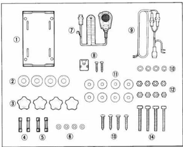
Accessories included with the IC-M600: QTY.
① Mounting bracket....1
② Rubber feet....4
③ Mounting knobs 4
④ Spare fuses (30 A) 2
⑤ Spare fuses (4 A)....2
⑥ Flat washers (for mounting knobs) 4
⑦ Microphone (EM-48) 1
⑧ Microphone hanger and screws.... 1 set
⑨ DC power cable (OPC-077).... 1
⑩ Spring washers 8
⑪ Flat washers....8
⑫ Nuts....8
13 Self-tapping screws....4
⑭ Hex head bolts 4
1
PANEL DESCRIPTION
■ Switches and controls
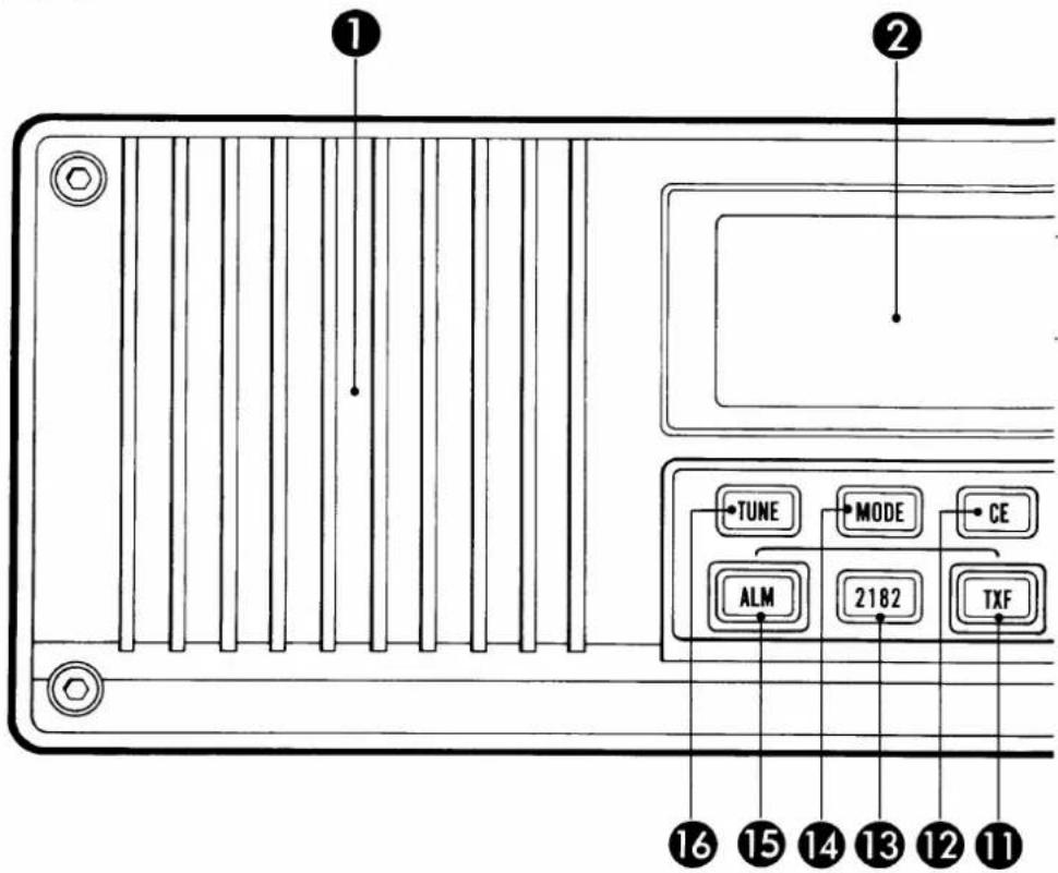
① INTERNAL SPEAKER
Operates while the transceiver is receiving and "⌘" is not displayed.
② FUNCTION DISPLAY (p. 4)
Indicates the current operating frequency, channel, mode and additional information.
③ MAIN DIAL
Selects an operating channel (pgs. 11, 12) or operating frequency (p. 13).
Selects an operating band after pushing [FUNC]. (p. 12)
④ CLARITY SWITCHES [CLAR] (pgs. 15, 16)
Shifts only the receive frequency ±150 Hz in 10 Hz steps.
- Clarity indicator appears and shows the shifting level.
- Clears the shift frequency when both [▲] and [▼] are pushed simultaneously.
⑤ VOLUME SWITCHES [VOL] (p. 15)
Adjusts the audio level.
- The volume level is displayed by the S/RF indicator while adjusting the volume level.
- When both [▲] and [▼] are pushed simultaneously, audio is muted.
⑥ POWER SWITCHES [POW]
Turn power ON and OFF.
- Turns power ON when either switch is pushed.
- Turns power OFF when both switches are pushed simultaneously.
⑦ FUNCTION SWITCH [FUNC] (pgs. 15, 16)
Activates the secondary functions of the switches and main dial.
| KEY | SECONDARY FUNCTION (After pushing [FUNC]) |
| [1] | Dimmer switch [DIM]•Turns backlighting ON and OFF. |
| [2] | Squelch switch [SQL]•Turns the squelch function ON and OFF. |
| [3] | Noise blanker switch [NB]•Turns the noise blanker function ON and OFF. |
| [4] | Speaker-off switch [SP]•Mutes received audio and the beep tone from the internal speaker. |
| [5] | AGC switch [AGC]•Turns the AGC (Automatic Gain Control)circuit ON and OFF. |
⑧ RECEIVE FREQUENCY ENTER SWITCH [RX]
Stores a duplex ITU channel or memory channel after keyboard entry. (pgs. 11, 12)
Enters a receive frequency. (p. 13)
Stores a receive frequency in a memory channel. (p. 18)
Sets the transceiver to select RF gain after pushing [FUNC]. (p. 15)
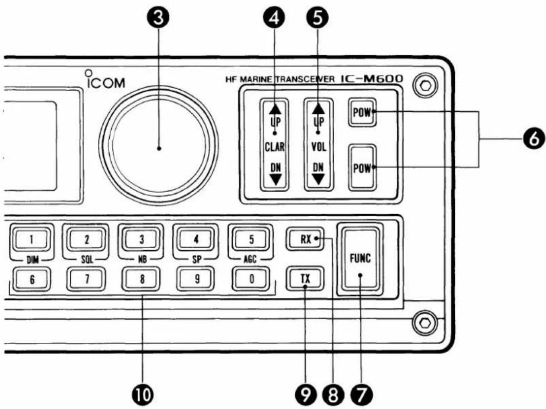
⑨ TRANSMIT FREQUENCY ENTER SWITCH [TX]
Allows entry of the transmit channel for cross channel operation. (p. 20)
Sets the transceiver for writing of a transmit frequency. (p. 18)
Stores a transmit frequency in a memory channel. (p. 18)
Sets the transceiver to select RF output power after pushing [FUNC]. (p. 17)
⑩ KEYBOARD
Numeral keys perform tuning and activate functions. Some numeral keys have secondary functions as shown in the table at left. To activate the secondary function of the keys, push [FUNC] before pushing the keys.
See pgs. 11\~13 for tuning operation, or see the page at left for a description of secondary functions.
⑪ TRANSMIT FREQUENCY CHECK SWITCH [TXF]
(p. 17)
While pushing this switch, the operating frequency changes from the receive frequency to the transmit frequency to check whether the transmit frequency is busy or not.
⑫ CLEAR SWITCH [CE]
Clears input digits and retrieves the previous key input.
Sets the transceiver for the 100 Hz tuning step. (p. 13)
Sets the transceiver to store a frequency.
⑬ 2182 kHz SWITCH [2182] (p. 11)
Accesses the 2182 kHz emergency and distress call frequency instantly during any operating condition.
⑭ MODE SWITCH [MODE]
Selects the desired operating mode.
⑮ ALARM SWITCH [ALM] (p. 19)
Selects the 2182 kHz emergency frequency; also turns ON and OFF the alarm function.
Transmits alarm signals on 2182 kHz when pushing this switch together with [TXF].
⑯ ANTENNA TUNER SWITCH [TUNE]
Starts the tuning of an optional AT-120E HF AUTOMATIC ANTENNA TUNER.
1 PANEL DESCRIPTION
Rear panel
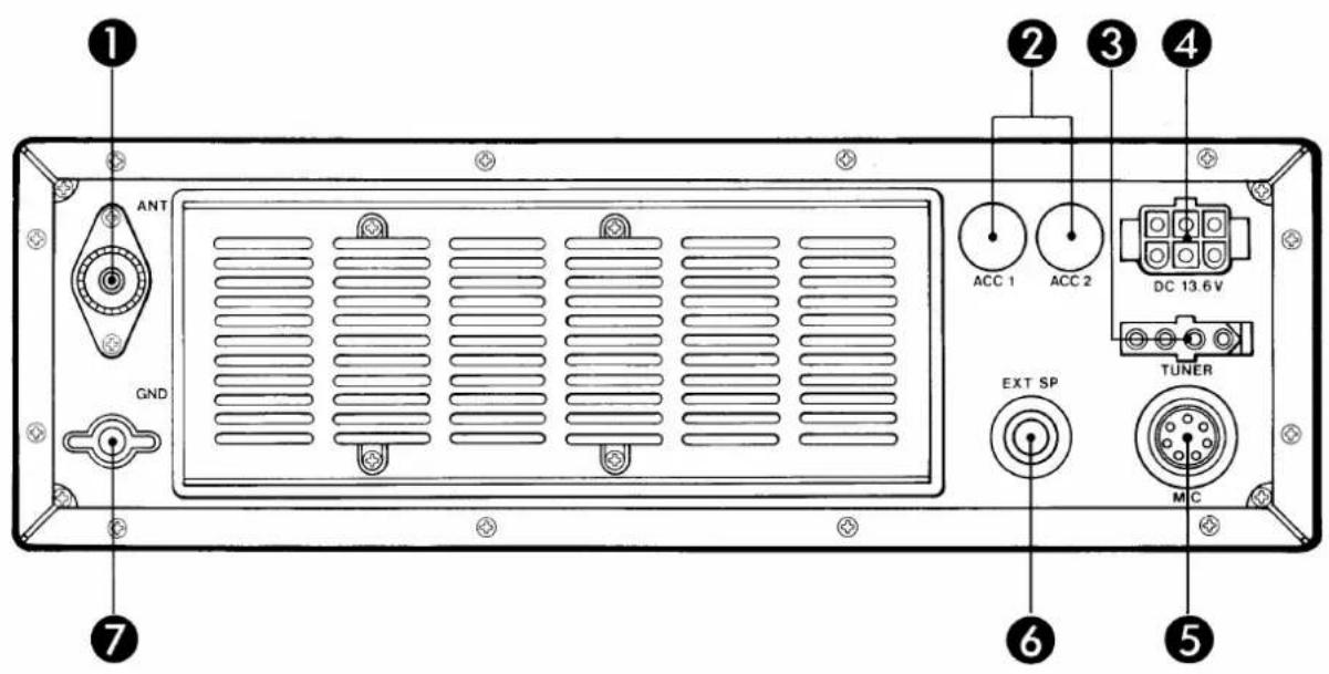
① ANTENNA CONNECTOR [ANT] (p. 8)
Connects an antenna cable. A PL-259 plug must be used.
CAUTION: Transmitting without an antenna may damage the transceiver.
② SPARE HOLES [ACC1], [ACC2] (p. 10)
Optional ACC cables, OPC-302 and OPC-303, can be installed here. External equipment may require sockets with ACC cables.
③ ANTENNA TUNER CONNECTOR [TUNER] (p. 9)
Connects the control cable of an optional AT-120E HF AUTOMATIC ANTENNA TUNER.
④ DC POWER CONNECTOR [DC 13.6 V] (pgs. 6, 8)
Connects the supplied DC power cable to an external 13.6 V DC power source.
⑤ MIC CONNECTOR [MIC]
Connects the supplied microphone or an optional HS-50 HANDSET.
- The internal speaker does not function when the microphone is not connected to [MIC].
⑥ EXTERNAL SPEAKER JACK [EXT SP]
Connects a 4\~8 Ω speaker, if desired.
- The internal speaker can be turned OFF using the speaker-off function (Push [FUNC], then [4]).
⑦ GROUND TERMINAL [GND] (p. 8)
To prevent electrical shocks, interference from other electronic equipment and other problems, be sure to ground the transceiver to a good earth point.
(See p. 8 for ground connection examples.)
■ Function display
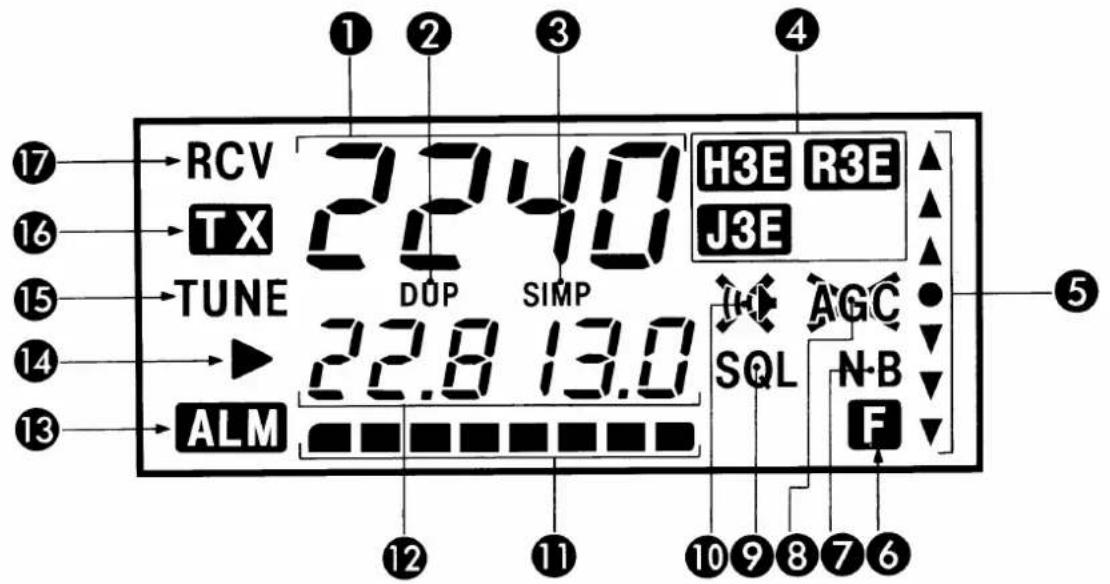
① CHANNEL INDICATOR
Displays the selected ITU or memory channel number.
- Hyphenated numbers appear when a simplex ITU channel is selected.
② DUPLEX INDICATOR
Appears when a duplex channel is selected.
③ SIMPLEX INDICATOR
Appears when a simplex channel is selected.
④ MODE INDICATORS
Indicate the operating mode.
- The mode indicator disappears while an optional antenna tuner is tuning.
⑤ CLARITY INDICATOR
Indicates the clarity setting level every 50 Hz.
- “▲” arrows indicate that the receive frequency has been shifted higher than the displayed frequency.
- “▼” arrows indicate that the receive frequency has been shifted lower than the displayed frequency.
⑥ FUNCTION INDICATOR
Appears when the [FUNC] switch is pushed.
⑦ NOISE BLANKER INDICATOR
Appears when the noise blanker function is turned ON.
⑧ AGC OFF INDICATOR
Appears when the AGC (Automatic Gain Control) circuit is turned OFF.
⑨ SQUELCH INDICATOR
Appears when the squelch function is turned ON.
⑩ SPEAKER-OFF INDICATOR
Appears when the internal speaker is turned OFF.
⑪ S/RF INDICATOR
Displays the relative received signal strength while receiving.
Displays the volume level while adjusting the volume.
Displays the antenna current level while transmitting, when an optional AT-120E is connected.
⑫ FREQUENCY READOUT
Displays the operating frequency.
⑬ ALARM INDICATOR
Appears when the alarm function is activated.
⑭ FREQUENCY SETTING INDICATOR
Appears during frequency setting.
• The [CE] switch turns the indicator ON and OFF.
⑮ TUNING INDICATOR
Blinks while an optional antenna tuner is tuning.
16 TRANSMIT INDICATOR
Appears while transmitting or checking the transmit frequency.
Blinks while setting the transmit frequency.
⑰ RECEIVE INDICATOR
Appears when the squelch opens.
2 INSTALLATION
■ Mounting the transceiver
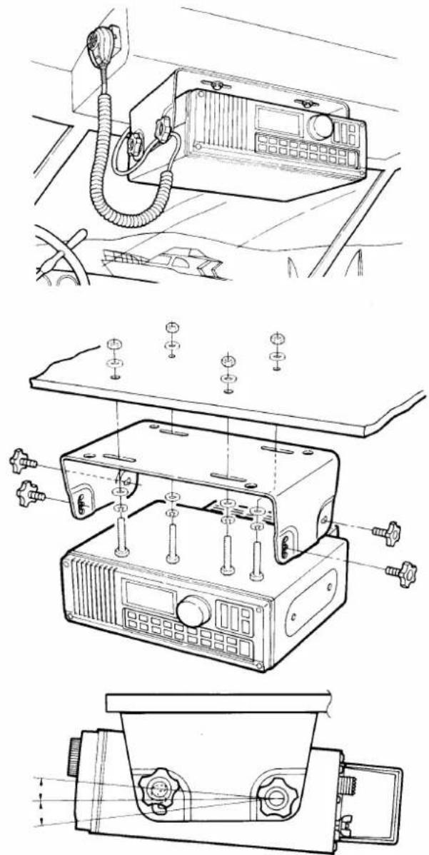
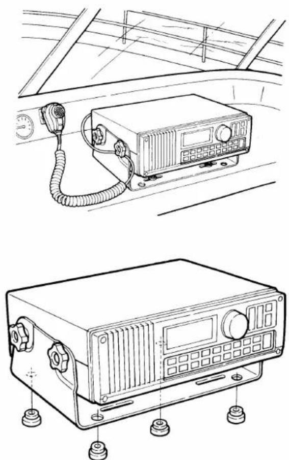
The bracket supplied with your transceiver allows "overhead" or "dashboard" mounting. Read the following installation instructions carefully.
WARNING: The transceiver may come loose during wave shocks or vibrations when mounted without the proper bolts, nuts, etc.
KEEP the transceiver, microphone and an external speaker at least 1 m (3.3 ft.) away from the ship's magnetic navigation compass.
1) Select a dry, well-ventilated location that provides easy access to the front panel for steering safety.
2) DO NOT select areas subject to extreme heat, cold, vibrations, or areas near electromagnetic sources or in direct sunlight.
3) Install the mounting bracket as shown in the diagram below so the transceiver is adequately supported, thus protecting it from wave shock and vibrations.
4) Mount the transceiver and adjust the viewing angle; then, tighten the mounting knobs.
• Overhead mounting
natural_image
Technical line drawings of a portable radio device with attached cables and control panels (no text or symbols)Adjust installation angle for good visibility.
- Dashboard mounting
natural_image
Technical line drawings of a vehicle front panel and its internal electronic device (no text or symbols present)To install the transceiver for dashboard mounting, attach the supplied rubber feet to the mounting bracket as above so that the transceiver can be moved to suit your operation needs; or use the supplied hardware as shown at left for fixed installation.
Rear panel connections
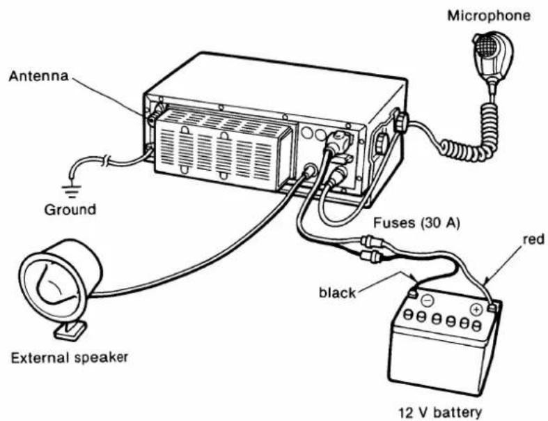
The transceiver requires at least 4 cable connections:
- Supplied DC power cable (OPC-077)
- Ground cable
- Antenna coaxial cable
- Supplied microphone (EM-48)
(1) DC power cable
Connect the cable to a 13.6 V DC power source (at least 30 A) directly. See the diagram below and p. 8 for details.
(2) Ground cable
The transceiver MUST have an adequate ground connection. See p. 8 for details.
(3) Antenna coaxial cable
Connect a 50 Ω coaxial cable with a PL-259 connector. See p. 8 for details.
(4) Microphone
Connect the supplied microphone to [MIC].
- Rear panel connections
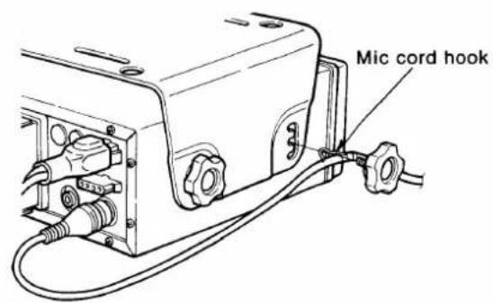
- Mic cord hook attachment
- Mic connector pin arrangement
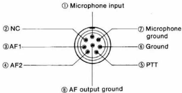
Looking at the rear panel, you will see the above pin arrangement.
2 INSTALLATION
■ Installation example
The following diagrams show a typical installation of the IC-M600 with the AT-120E. Installation consists of the following 5 major components:
- IC-M600 HF MARINE TRANSCEIVER
- AT-120E HF AUTOMATIC ANTENNA TUNER
- DC power source
- Antenna
- Ground
(1) IC-M600 installation
See pgs. 5 and 6 for installation and connections.
(2) Optional AT-120E installation
The AT-120E ensures a matched condition between the transceiver and antenna at all times. See p. 9 for installation and connection procedures.
(3) DC power source
The IC-M600 requires regulated DC power; 13.6 V and at least 30 A. See p. 8 for the power cable connections.
(4) Antenna
The AT-120E requires an antenna wire or element at least 7.6 m (25 ft.) long for covering all HF marine bands. See pgs. 8 and 9 for more information.
(5) Ground
Proper grounding is very important. See p. 8 for a transceiver and tuner ground system example.
• Installation example with the optional AT-120E
![AT-120E Ground Coaxial cable IC-M600 to [ANT] AT-120E to [TUNER] Ground (See p. 8) AT-120E control cable](/content/2026/05/777899/images/9b64192b8bc400c94e2062851426da58ca51ac9f2ce964060b95f645a4317fbb.jpg)
Ground connections
The transceiver and antenna tuner MUST have an adequate ground connection. Otherwise, the overall efficiency of the transceiver and antenna tuner installation will be reduced. Electrical shocks and interference from other equipment could also occur.
For best results, use the heaviest gauge wire or strap available and make the connection as short as possible.
For wooden or fiberglass boats, make the ground connection to the engine block or other large metal objects, or use a copper ground plate, etc. See the diagram at right for an example of grounding.
- Ground system example
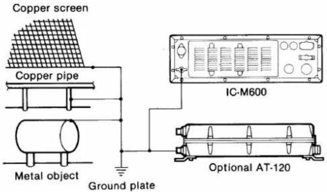
Antenna connections
Most stations operate with a whip or long wire (insulated backstay) antenna. However, these antennas cannot be connected directly to the transceiver since their antenna impedance is not matched with the transceiver antenna connector. Keep the following procedures in mind:
- Whip or long wire antennas require an optional AT-120E HF AUTOMATIC ANTENNA TUNER or an optional MN-100 or MN-100L ANTENNA MATCHER. (p. 9)
- A 50 Ω impedance antenna is required. Ask your Icom Dealer for details.
• PL-259 connector attachment
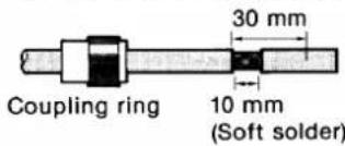
1) Slide the coupling ring over the coaxial cable.
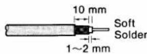
2) Strip the cable as shown in the figure, and soft-solder the center conductor.
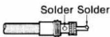
3) Slide the connector body onto the cable and solder.
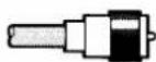
4) Screw the coupling ring onto the connector body.
1 mm = 1/32 in
Power source
The IC-M600 requires regulated DC power: 13.6 V and at least 30 A. There are 3 ways to supply power:
- Connect the power cable directly to the 12 V battery in the boat.
- Connect an optional PS-60 DC POWER SUPPLY to use an AC outlet.
- Connect an optional PS-66 DC-DC CONVERTER to use a 19\~32 V DC power source.
CAUTION: The supplied DC power cable MUST be used to provide power to the transceiver. AVOID exceeding the 3 m (10 ft.) of length of the DC power cable. If it is necessary to make a run of over 3 m, use #6 or a similar cable instead of the supplied DC power cable for a maximum run of 6 m (20 ft.).
• DC power cable connection
CAUTION: Cables MUST be connected to the terminals of a 12 V battery when using a battery as the power source.
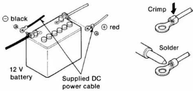
3
EXTERNAL EQUIPMENT CONNECTIONS
■ AT-120E HF AUTOMATIC ANTENNA TUNER
• AT-120E cable connections
![50 Ω coaxial cable (Sold separately) to [ANT] IC-M600 to [TUNER] Ground Optional AT-120E Antenna wire AT-120E control cable (Sold separately)](/content/2026/05/777899/images/0b079e1298e25bf37bdf08f986240f0dc74bb489658581efd76d2cef67d3e042.jpg)
• Control cable connections
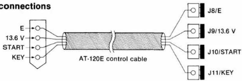
■Internal setting for a non-lcom antenna tuner
Front panel
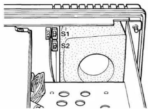
Some non-Icom tuners may be used with the IC-M600. Please ask your dealer or marina if you wish to connect one. The following internal setting may be required for connection.
S1 (Start port level)


Supplies 8 V when pushing [TUNE]. (used for the AT-120E)
Grounded when pushing [TUNE].
S2 (Key port input)


Accepts "HIGH" as an answer back signal. (used for the AT-120E)
Accepts "LOW" as an answer back signal.
MN-100, MN-100L ANTENNA MATCHERS
- Connecting a wire with wire clamps
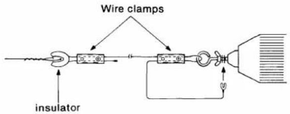
• Using the MN-100 with a long wire antenna
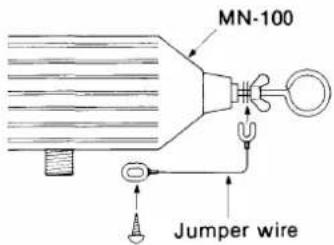
- Typical installation
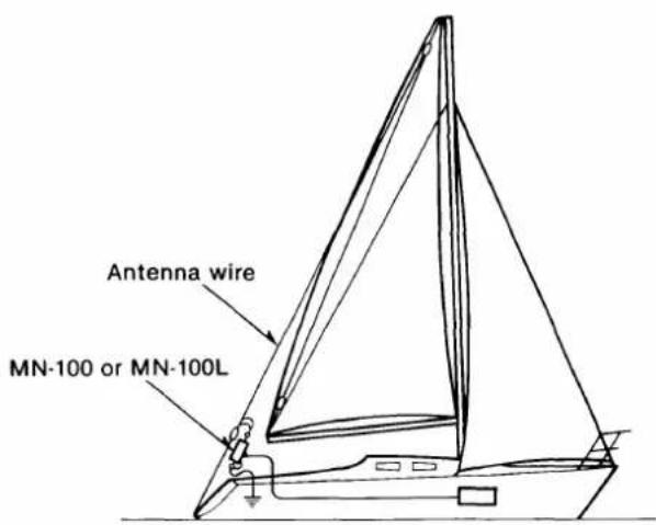
■ OPC-302, OPC-303 ACC CABLES
The OPC-302 and OPC-303 ACC CABLES provide simple and sure connections for external equipment. The OPC-302 and OPC-303 are installed in the ACC2 and ACC1 SOCKETS respectively. Refer to p. 20 for ACC cable installation.
ACC1 SOCKET
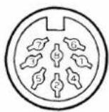
ACC2 SOCKET
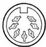
| PIN NO. | PIN NAME | DESCRIPTION |
| 1 | SCAN | Scan control input from external equipment. |
| 2 | GND | Connected to the chassis ground. |
| 3 | SEND | Transmits when grounded. |
| 4 | MOD | Modulation input for external equipment. |
| 5 | AF | Fixed AF output regardless of [VOL]. |
| 6 | SQL S | Squelch output.Grounded when the squelch is open. |
| 7 | 13.6 V | 13.6 V output. |
| 8 | ALC | ALC voltage input. |
| PIN NO. | PIN NAME | DESCRIPTION |
| 1 | 8 V | Regulated 8 V output. |
| 2 | GND | Same as ACC1 pin 2. |
| 3 | SEND | Same as ACC1 pin 3. |
| 4 | BAND | Band voltage output. Varies with marine band. |
| 5 | ALC | Same as ACC1 pin 8. |
| 6 | RLC | Goes to ground when transmitting. |
| 7 | 13.6 V | Same as ACC1 pin 7. |
4
SELECTING A CHANNEL
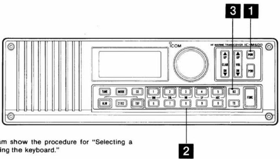
1\~3 in the diagram show the procedure for "Selecting a memory channel, using the keyboard."
■ Direct selection of 2182 kHz
1 Push either [POW] to turn ON power.
2 Push [2182] to select the 2182 kHz emergency and distress call frequency quickly.
• The channel indicator shows "0."
• The operating mode automatically changes to H3E.
3 To return to the previous operating condition, push [2182] again.
NOTE: When 2182 kHz is selected via [2182], the operating frequency cannot be changed. Push [2182] to return to the normal operating condition.
■ Selecting a memory channel
The IC-M600 has 99 user-programmable memory channels and 314 ITU channels.
There are 2 ways to select the desired memory channel:
- Using the main dial.
- Using the keyboard.
(1) Using the keyboard
1 Push either [POW] to turn ON power.
2 Enter your desired channel via the keyboard.
- A user-programmable memory channel is automatically selected when channel 1\~99 is entered.
- An ITU channel is automatically selected when a channel number higher than 401 is entered. An ITU channel list is available separately.
- ITU simplex channels cannot be selected via the keyboard. Use the main dial as described at right.
NOTE: The keyboard cannot enter channel numbers when “▶” or “2.182.0” appears on the function display.
To remove “▶,” push [CE]; to remove “2.182.0,” push [2182].
3 Push [RX] to select the channel number.
- The frequency of the selected channel appears in the frequency readout.
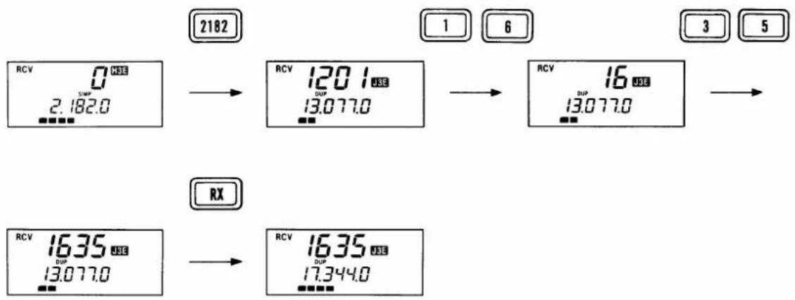
EXAMPLE: Selecting channel 1635.
EXAMPLE: Selecting channel 22-5.
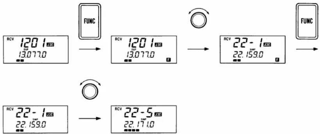
flowchart
graph TD
    A["RCV 120.1 USE<br>DUP<br>13.077.0"] --> B["FUNC"]
    B --> C["RCV 120.1 USE<br>DUP<br>13.077.0"]
    C --> D["RCV 22 - 1 USE<br>SWAP<br>22.159.0"]
    D --> E["FUNC"]
    F["RCV 22 - 1 USE<br>SWAP<br>22.159.0"] --> G["FUNC"]
    G --> H["RCV 22 - 5 USE<br>SWAP<br>22.171.0"]
(2) Using the main dial
1 Push either [POW] to turn ON power.
2 Push [FUNC].
- "F" appears on the function display.
3 Rotate the main dial until your desired band appears at the channel indicator.
• The thousands and hundreds digits of the channel indicator show the operating band.
- “-” appears on the channel indicator when an ITU simplex channel is selected.
4 Push [FUNC] to enter the channel selecting condition.
- "F" disappears.
5 Rotate the main dial to select the desired operating channel.
IC-M600 MEMORY CHANNELS
| CHANNEL No. | DESCRIPTION | CHANNEL No. | DESCRIPTION |
| 1~99 | User-programmable channels | 1601~1656 | 16 MHz ITU duplex channels |
| 401~427 | 4 MHz ITU duplex channels | 16-1~16-9 | 16 MHz ITU simplex channels |
| 4-1~4-9 | 4 MHz ITU simplex channels | 1801~1815 | 18 MHz ITU duplex channels |
| 601~608 | 6 MHz ITU duplex channels | 18-1~18-9 | 18 MHz ITU simplex channels |
| 6-1~6-9 | 6 MHz ITU simplex channels | 2201~2253 | 22 MHz ITU duplex channels |
| 801~832 | 8 MHz ITU duplex channels | 22-1~22-9 | 22 MHz ITU simplex channels |
| 8-1~8-9 | 8 MHz ITU simplex channels | 2501~2510* | 25 MHz ITU duplex channels |
| 1201~1241 | 12 MHz ITU duplex channels | 25-1~25-9* | 25 MHz ITU simplex channels |
| 12-1~12-9 | 12 MHz ITU simplex channels |
*25 MHz ITU channels are used for receiving only.
5 SETTING A FREQUENCY
■ Setting a receive frequency
The IC-M600 has 0.5\~30.0 MHz general coverage capability. To set a receive frequency, follow this procedure:
1 Push [2182] if the emergency frequency has been selected.
2 Select any channel except an ITU simplex channel.
3 Push [CE].
- “▶” appears on the function display.
4 Enter the desired frequency up to the 100 Hz unit via the keyboard.
- Push [CE] to clear input digits.
5 Push [RX] to enter the receive frequency.
- DO NOT push and hold [RX] when operating on a memory channel (1\~99). The displayed frequency will be cleared and a new frequency will be stored in the memory channel.
6 To clear this function and return to the previous frequency, push [CE] again.
- “▶” disappears.
NOTE: A frequency set by the above procedure will be cleared once the memory channel is changed. To write the frequency into a memory channel, see Section 9, MEMORY OPERATION.
■ Setting a transmit frequency
To set a transmit frequency manually, set a receive frequency and mode, and then follow the "Setting a receive frequency" procedure at left, substituting steps 2, 5 and 6 with the following:
2 Select a user-programmable memory channel (1\~99), and then push [TX] to set a transmit frequency.
- "TX" blinks on the function display.
5 Push and hold [TX] to enter the transmit frequency.
• The frequency is stored in the memory channel.
6 Push [TX] to display the receive frequency.
■ Changing the frequency in 100 Hz steps
1 Push [2182] if the emergency frequency has been selected.
2 Push [CE].
- "▶" appears on the function display.
3 Rotate the main dial.
- The displayed frequency (receive frequency) changes in 100 Hz steps.
4 To clear this function and return to the previous frequency, push [CE] again.
- "▶" disappears.
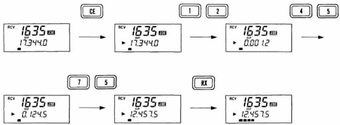
EXAMPLE: Selecting 12.4575 MHz.
OPERATING RULES AND GUIDELINES
Before transmitting, monitor the channel you wish to use so as to avoid interrupting transmissions already in progress.
(1) Call procedures
Calls must be properly identified and time limits must be respected.
1) Give your call sign each time you call another vessel or coastal station. If you have no call sign, identify the station by giving your vessel name and the name of the licensee.
2) Give your call sign at the end of each transmission that lasts more than 3 min.
3) You must break and give your call sign at least once every 15 min. during long ship-to-shore calls.
4) Keep your unanswered calls short, less than 30 sec. Do not repeat a call for 2 min.
5) Unnecessary transmissions are not allowed.
(2) Priorities
1) Read all the rules and regulations pertaining to priorities and keep an up-to-date copy handy. Safety and distress calls take priority over all others.
2) False or fraudulent distress signals are prohibited and punishable by law.
(3) Privacy
1) Information overheard but not intended for you cannot lawfully be used in any way.
2) Indecent or profane language is prohibited.
(4) Logs
1) All distress, emergency and safety calls must be recorded in complete detail. Log data activity is usually recorded in 24 hour time. Universal Time (also known as UTC) is frequently used.
2) Adjustments, repairs, channel frequency changes and authorized modifications affecting electrical operation of the equipment must be kept in the maintenance log; entries must be signed by the authorized licensed technician performing or supervising the work.
(5) Radio licenses
SHIP STATION LICENSE
When your craft is equipped with an HF marine transceiver such as the IC-M600 you must have a current radio station license before using the equipment. It is unlawful to operate a ship station which is not licensed.
Inquire through your Icom Dealer or the appropriate government agency for a Ship Radiotelephone License application. This government-issued license states the call sign which is your craft's identification for radio purposes.
OPERATOR'S LICENSE
A Restricted Radiotelephone Operator Permit is the license most often held by small vessel radio operators when a radio is not required for safety purposes. You can usually obtain this permit by mail.
The Restricted Radiotelephone Operator Permit must be posted or kept with the operator. Only a licensed radio operator may operate a transceiver.
However, non-licensed individuals may talk over a transceiver if a licensed operator starts, supervises, and ends the call, and makes the necessary log entries.
Keep a copy of the current government rules and regulations handy.
7
RECEIVING
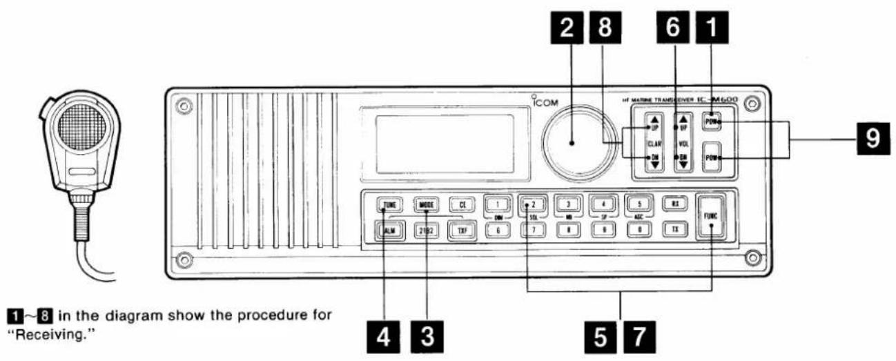
NOTE: The microphone MUST be connected to the mic connector or no audio will be emitted from the speaker.
■ Receiving
1 Push either [POW] to turn ON power.
2 Select the desired operating channel or frequency.
- For selecting a channel, see pgs. 11 and 12.
- For setting a frequency, see p. 13.
3 Push [MODE] to select the desired operating mode.
4 Push [TUNE] when an optional AT-120E HF AUTOMATIC ANTENNA TUNER is connected.
• [TUNE] is effective only when the AT-120E is connected.
- Push [TUNE] each time you change the operating band.
- The AT-120E automatically tunes the connected antenna wire or element.
- "TUNE" blinks on the function display while the AT-120E is tuning.
5 Push [FUNC] and then [2/SQL] to turn OFF the squelch function when the squelch indicator appears.
6 Push [UP] or [DN] on [VOL] to obtain the desired loudness.
7 Push [FUNC] and then [2/SQL] to turn ON the squelch function when necessary.
- "SQL" appears on the function display.
• The function mutes audio output from the speaker when receiving no voice signals.
8 Push [UP] or [DN] on [CLAR] to obtain clear reception for an off-frequency signal.
9 Push both [POW] switches to turn OFF power.
■Adjusting the RF gain
The gain of the receiver RF stage can be changed in 7 steps as follows:
1 Push [FUNC].
- "F" appears on the function display.
2 Push [RX].
- "rF" and the previously selected RF gain appear.
3 Push the appropriate number to select the desired RF gain.
| KEY | RF GAIN | FUNCTION DISPLAY |
| [0]~[2] | Minimum | rF-0~rF-2 |
| [3]~[7] | Mid-range | rF-3~rF-7 |
| [8], [9] | Maximum | rF-8, rF-9 |
- The S/RF indicator shows the receivable signal strength level.
- "rF" disappears and the new RF gain has been programmed.
• Using the noise blanker function
The noise blanker function reduces pulse noise such as that coming from engine ignitions.
Push [FUNC] and then [3/NB] to turn ON the noise blanker function and reduce the noise level.
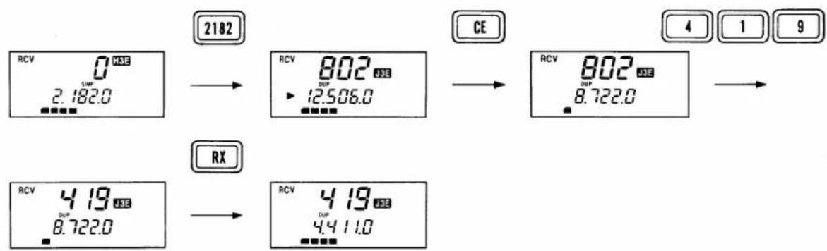
EXAMPLE: Receiving on channel 419 in J3E mode.
flowchart
graph LR
    A["RCV 0 MSE<br>2.182.0"] --> B["RCV 802 MSE<br>12.506.0"]
    B --> C["RCV 802 MSE<br>8.722.0"]
    D["CE"] --> C
    E["RCV 419 MSE<br>8.722.0"] --> F["RCV 419 MSE<br>4.411.0"]
    G["RX"] --> F
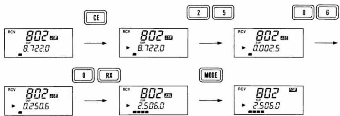
EXAMPLE: Receiving on 2506.0 kHz in R3E mode.
flowchart
graph LR
    A["CE"] --> B["RCV 802 DUF 8.722.0"]
    B --> C["RCV 802 DUF 8.722.0"]
    C --> D["RCV 802 DUF 0.002.5"]
    D --> E["MODE"]
    E --> F["RCV 802 DUF 2.506.0"]
    F --> G["Mode"]
• Using the squelch function
This function detects signals with voice components and squelches unwanted signals such as signals with no modulation, beat signals and noise component signals. This function allows you quiet waiting periods.
While receiving a very weak signal, turn OFF the squelch function.
- Receive indicator
When the squelch is open, the receive indicator appears.
• Using the AGC switch
The RF gain is controlled by the AGC (automatic gain control) circuit. While searching for a channel or receiving a weak signal, push [FUNC] and then [5/AGC] to turn OFF the AGC circuit.
• Using the dimmer switch
The backlighting can be turned ON and OFF with [FUNC] and [1/DIM] for adjustment with the surrounding brightness.
- Adjusting the clarity
[UP] or [DN] on [CLAR] shifts the receive frequency ±150 Hz in 10 Hz steps to obtain clear reception for an off-frequency signal.
To cancel the clarity setting, push [UP] and [DN] on [CLAR] simultaneously.
• Using the speaker-off switch
Audio output from the internal speaker can be muted with [FUNC] and [4/SP]. This is useful when you do not need to listen to receive signals, or when an external speaker is connected to the rear panel [EXT SP].
8
TRANSMITTING
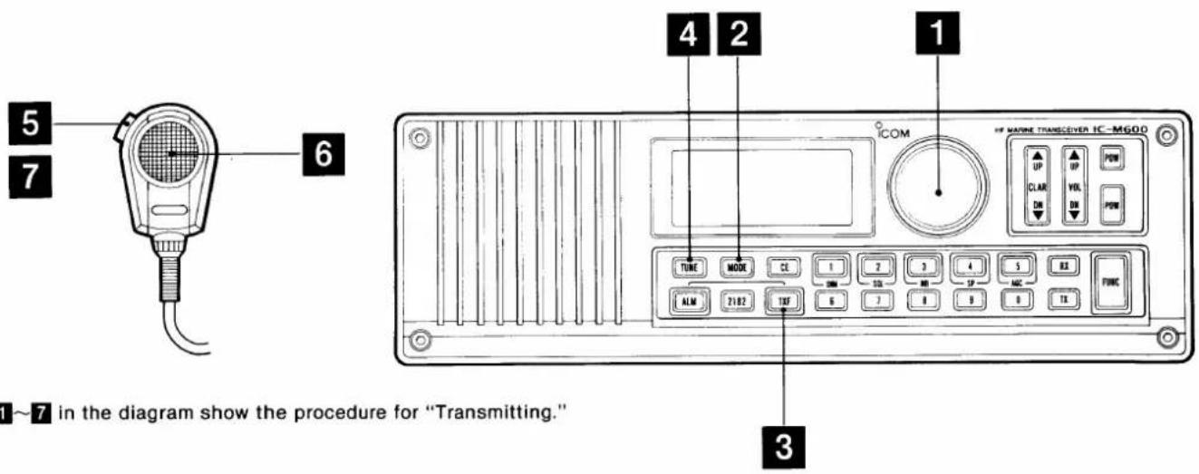
CAUTION: Transmitting without an antenna may damage the transceiver.
■Transmitting
1 Select the desired operating channel or frequency.
- For selecting a channel, see pgs. 11 and 12.
- For setting receive and transmit frequencies, see p. 13.
2 Push [MODE] to select the desired operating mode.
3 Push and hold [TXF] to check whether the transmit frequency is busy or not.
• The function display changes from the receive frequency to the transmit frequency.
4 Push [TUNE] when an optional AT-120E HF AUTOMATIC ANTENNA TUNER is connected.
• [TUNE] is effective only when the AT-120E is connected.
- Push [TUNE] each time you change the operating band.
- The AT-120E automatically tunes the connected antenna wire or element.
- "TUNE" blinks on the function display while the AT-120E is tuning.
5 Push and hold the PTT switch on the microphone.
- "TX" appears on the function display.
6 Speak into the microphone at your normal voice level.
7 Release the PTT switch to receive.
Cross channel operation is available with the IC-M600 for receiving on one channel and transmitting on another. See p. 20.
■ Setting the transmit power
High or low transmit power can be selected as follows:
NOTE: The transmit power setting affects all channels.
1 Push [FUNC].
- "F" appears on the function display.
2 Push [TX].
- "Po" and the previously selected output power number appear.
3 Push the appropriate number to select the desired output power.
| KEY | OUTPUT POWER | FUNCTION DISPLAY |
| [3]~[9] | 150 W (High) | Po-3 |
| [2] | 60 W (Low) | Po-2 |
| [1] | 60 W (Low) | Po-1 |
- "Po" disappears and the new output power level has been programmed.
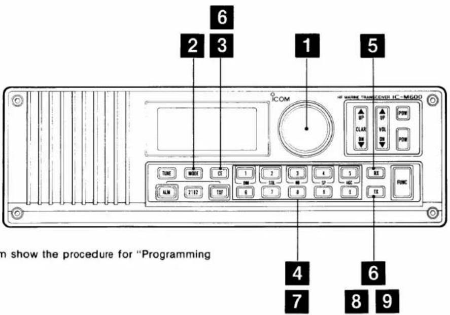
1\~9 in the diagram show the procedure for "Programming a frequency."
■ Programming a frequency
The IC-M600 has 99 user-programmable memory channels. The transmit and receive frequencies can be separately programmed.
1 Select the desired memory channel to be used.
- Channels 1\~99 are user-programmable memory channels.
- For selecting a memory channel, see pgs. 11 and 12.
2 Push [MODE] to select the desired operating mode.
- When the receive frequency has been cleared, the operating mode is not displayed. Write a frequency and then change the mode. See the procedures at right.
3 Push [CE].
- "▶" appears on the function display.
4 Enter the desired receive frequency via the keyboard. (p. 13)
5 Push and hold [RX] until "▶" disappears.
6 Push [TX] and then [CE].
- "TX" blinks and "▶" appears on the function display.
7 Enter the desired transmit frequency within the HF marine band via the keyboard.
• The frequency range of the HF marine band appears on p. 23.
8 Push and hold [TX] until "▶" disappears.
9 Push [TX] again to exit the transmit frequency setting condition.
NOTE: The ITU simplex channels can be changed to an operating band frequency using steps 1\~5 above. 9 simplex channels are available for each band.
■ Changing the operating mode
1 Select the desired memory channel to be changed.
• For selecting a memory channel, see pgs. 11 and 12.
2 Push [CE].
• "▶" appears on the function display.
3 Push [MODE] to select the desired operating mode.
4 Push and hold [RX] until "▶" disappears.
■ Clearing memory information
1 Select the desired memory channel to be cleared.
• For selecting a memory channel, see pgs. 11 and 12.
2 Push [CE].
• "▶" appears on the function display.
3 Push [0].
4 Push and hold [RX] until “▶” disappears to clear the receive frequency.
5 Push [TX] and then [CE].
• "TX" blinks and "▶" appears on the function display.
6 Push [0].
7 Push and hold [TX] until "▶" disappears to clear the transmit frequency.
8 Push [TX] again to exit the transmit frequency setting condition.
10 ALARM SIGNAL
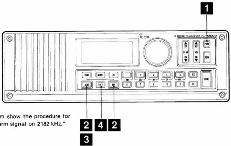
1\~4 in the diagram show the procedure for "Transmitting an alarm signal on 2182 kHz."
■Transmitting an alarm signal on 2182 kHz
The IC-M600 can transmit a 2-tone alarm signal on 2182 kHz.
WARNING: Transmitting an alarm signal when your vessel is not in distress is prohibited and punishable by law.
1 Push either [POW] to turn ON power.
2 Push [ALM] and [TXF] simultaneously.
- "TX" and "ALM" appear on the function display.
• The operating condition automatically changes to 2182 kHz and H3E mode. - 2-tone alarm signals are transmitted for approx. 50 sec.
- The optional AT-120E HF AUTOMATIC ANTENNA TUNER automatically tunes the connected antenna wire or element to 2182 kHz.
3 To stop transmitting the signal, push [ALM] again.
4 Push [2182] to return to the previous operating condition.
NOTE: If you wish to transmit an alarm signal in a mode other than H3E, push [2182]; then push [MODE] to select the desired mode. Then, proceed to step 2 above.
Distress call procedures
If your vessel requires assistance, contact other vessels and the Coast Guard by sending a distress call on 2182 kHz.
1 "MAYDAY, MAYDAY, MAYDAY."
2 "THIS IS......" (name of vessel)
3 "LOCATED AT...." (Vessel's position)
4 Give the reason for the distress call.
5 Explain what assistance you need.
6 Give additional information:
- Vessel type
• Vessel length - Vessel color
• No. of people onboard
■ Testing an alarm signal
The signal can be checked without transmitting an alarm.
1 Push [ALM].
• The operating condition automatically changes to 2182 kHz and H3E mode.
• The speaker emits alarm signals for approx. 50 sec.
- When the speaker-off function is activated, the alarm signal cannot be heard.
2 To stop testing, push [ALM] again.
3 Push [2182] to return to the previous operating condition.
CROSS CHANNEL OPERATION
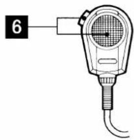
1\~6 in the diagram show the procedure for "Cross channel operation."
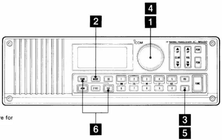
■ Cross channel operation
Cross channel operation allows you to operate 2 different memory channels for receiving and transmitting.
1 Select the desired receive channel. (pgs. 11, 12)
2 Push [MODE] to select the desired operating mode.
3 Push [TX].
- "TX" blinks on the function display.
4 Select the desired transmit channel:
- To select the channel using the keyboard, enter the desired channel number, and then push [TX].
- To select the channel using the main dial, rotate the main dial.
- To select a different transmit band, push [FUNC] and then rotate the main dial.
- ITU simplex channels cannot be used for cross channel operation.
5 Push [TX] to display the receive frequency.
6 Transmit on the frequency:
- Push [TUNE] when an optional AT-120E HF AUTOMATIC ANTENNA TUNER is connected.
- Push and hold [TXF] to check whether the transmit frequency is busy or not.
- Push and hold the PTT switch on the microphone.
- Speak into the microphone at your normal voice level.
- Release the PTT switch to receive.
NOTE: A channel set by the above procedure will be cleared once the channel is changed.
EXAMPLE: Receiving on channel 1635 and transmitting on channel 1208 in R3E mode.
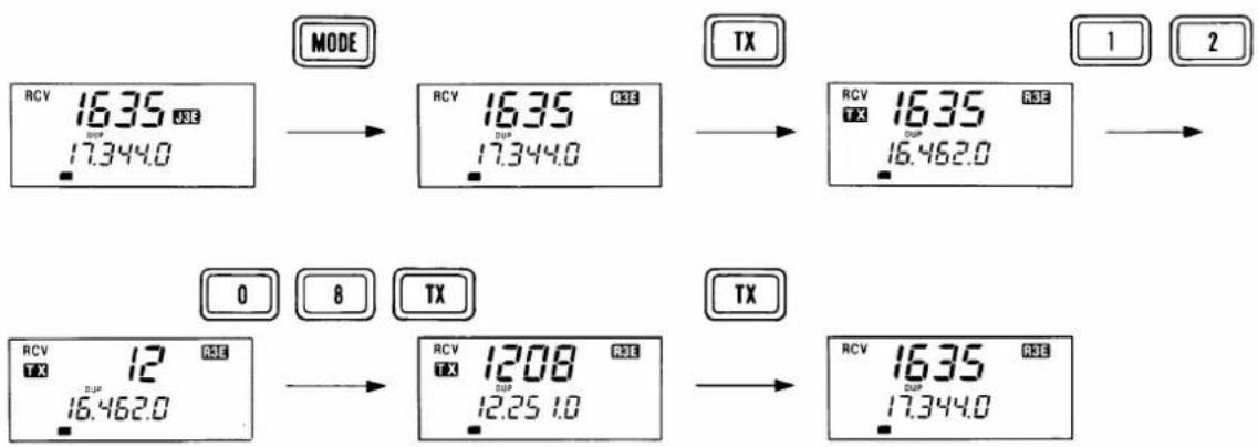
flowchart
graph LR
    A["MODE"] --> B["RCV 1635 DSE 17.344.0"]
    B --> C["TX"]
    C --> D["RCV 1635 DSP 17.344.0"]
    D --> E["1"]
    D --> F["2"]
    G["0"] --> H["RCV 12 DSE 16.462.0"]
    H --> I["TX"]
    I --> J["RCV 1208 DSP 12.25 1.0"]
    J --> K["TX"]
    K --> L["RCV 1635 DSP 17.344.0"]
12 MAINTENANCE
■ Replacing a fuse
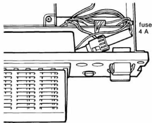
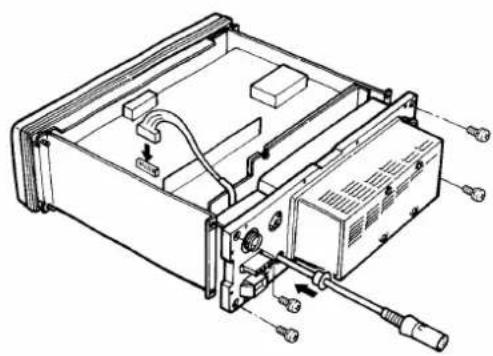
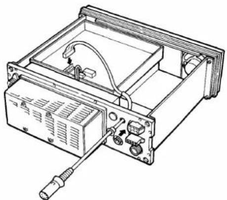
If a fuse blows or the transceiver stops functioning, try to find the source of the problem; then, replace the damaged fuse with a new, rated fuse. See figures below for replacing the fuse.
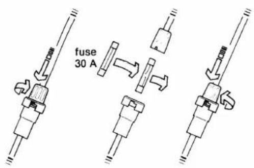
The IC-M600 has fuses installed in 2 different places:
- DC power cable : 30 A
- Inside the transceiver : 4 A
Cleaning
If the transceiver becomes dusty or dirty, wipe it clean with a dry, soft cloth.
AVOID the use of strong chemical agents such as benzine or alcohol, as they may damage the transceiver surfaces.

natural_image
Illustration of three plastic bottles with different internal patterns, enclosed in a circular frame (no text or symbols)ACC cables
The ACC cables may be used to connect external equipment such as a linear amplifier. See p. 10 for socket information.
natural_image
Technical line drawing of an electronic device chassis with ports and connectors (no text or symbols)OPC-303 for ACC (1) socket
natural_image
Technical line drawing of an electronic device with ports and wiring (no text or symbols)OPC-302 for ACC (2) socket
What appears to be trouble may not be damaging or hard to solve. Check the following chart before making any adjustments or sending the transceiver to an Icom Service Center.
| PROBLEM | POSSIBLE CAUSE | SOLUTION | REF. | |
| POWER | Power does not come ON when [POW] is pushed. | Power cable is improperly connected.Blown fuse. | Reconnect the cable securely.Check for the cause, then replace the fuse with a spare one. 2 kinds of fuses are installed in different places. | p. 8p. 21 |
| RECEIVE | No sound comes from the speaker. | The squelch is closed.The speaker-off switch is set at ON.Microphone is not connected to [MIC].Audio mute is activated. | Push [FUNC] and then [2] to open the squelch.Push [FUNC] and then [4] to turn OFF the speaker-off switch.Connect the supplied microphone to [MIC].Push [UP] or [DN] to cancel the mute. | p. 15p. 16p. 15p. 1 |
| Sensitivity is low and only strong signals are audible. | Antenna is not properly matched to the operating frequency.RF gain is set too low. | Push [TUNE] to tune the connected antenna system when an optional AT-120E is connected.Set the RF gain to the maximum. | p. 15p. 15 | |
| Received audio is unclear or distorted. | Wrong mode has been selected.Noise blanker is ON when receiving a strong signal.[CLAR] was set extremely [UP] or [DN]. | Push [MODE] to select the proper operating mode.Push [FUNC] and then [3] to turn OFF the noise blanker.Set [CLAR] to the proper receive audio output. | p. 15p. 15p. 16 | |
| TRANSMIT | Your signal does not reach distances as far away as usual. | The output power is low.Antenna is not properly matched to the operating frequency. | Select high output power.Push [TUNE] to tune the connected antenna system when an optional AT-120E is connected. | p. 17p. 17 |
| Transmitted signal is unclear or distorted. | Wrong mode has been selected.Microphone is held too close to your mouth. | Push [MODE] to select the proper operating mode.Speak into the microphone naturally and do not hold the microphone too close to your mouth. | p. 17p. 17 | |
| No contact is possible with another station. | Wrong transmit frequency has been set. | Push [TXF] to check the transmit frequency and store the correct transmit frequency. | p. 17 | |
| FUNCTION DISPLAY | Frequency cannot be changed in 100 Hz steps. | [CE] is not pushed. | Push [CE]; then, rotate the main dial. | p. 13 |
| Frequency cannot be set via the keyboard. | [CE] is not pushed before entering the frequency.Entered transmit frequency is not within the marine band or 160-m band. | Push [CE] to enter the desired frequency via the keyboard.Set a frequency within the marine band or 160-m band. | p. 13p. 23 | |
| The function display is not lit. | Backlighting has been turned OFF. | Push [FUNC] and then [1] to turn ON the backlighting. | p. 16 |
14 SPECIFICATIONS
GENERAL
| Frequency coverage | :Receive 0.5000~30.0000 MHz continuouslyTransmit 1.6000~ 1.9999 MHz2.0000~ 2.9999 MHz4.0000~ 4.9999 MHz6.0000~ 6.9999 MHz8.0000~ 8.9999 MHz12.0000~13.9999 MHz16.0000~17.9999 MHz18.0000~19.9999 MHz22.0000~22.9999 MHz |
| Mode | :J3E (USB), H3E, R3E |
| Antenna impedance | :50 Ω (unbalanced) |
| Power supply requirement | :13.6 V ±15% DC (negative ground) |
| Current drain | :Receive 3 A at max. audio outputTransmit 30 A at max. RF output power |
| Usable temperature range | :-10°C~+60°C |
| Frequency stability | :±20 Hz (-10°C~+60°C) |
| Dimensions | :287(W)×90(H)×233(D) mm11.3(W)×3.5(H)×9.2(D) in(projections not included) |
| Weight | :6.75 kg; 14.9 lb |
TRANSMITTER
- Output power (PEP) : High 150 W, Low 60W
- Spurious emissions : 60 dB below peak output power
- Carrier suppression (J3E) : 40 dB
- Unwanted sideband suppression : 55 dB below peak output power
(with 1500 Hz AF input) - Microphone impedance : 600 Ω
RECEIVER
| • Sensitivity (for 10 dB S/N) | : | J3E, R3E | 0.5~2.0 MHz | 6.3 μV |
| 2.0~30.0 MHz | 0.5 μV | |||
| H3E | 0.5~2.0 MHz | 32 μV | ||
| 2.0~30.0 MHz | 3.2 μV | |||
| • Spurious response rejection | : | -70 dB | ||
| • Audio output power | : | 5.0 W with a 4 Ω load | ||
| • Audio output impedance | : | 4~8 Ω | ||
| • Clarity variable range | : | ±150 Hz in 10 Hz steps |
All stated specifications are subject to change without notice or obligation.
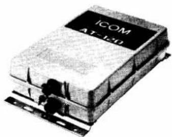
AT-120E HF AUTOMATIC
ANTENNA TUNER
natural_image
Exterior view of a rectangular electronic device labeled 'ICOM AT-120' (no additional text or symbols visible)The new ITU version AT-120E matches the IC-M600 to a long wire or whip antenna system.
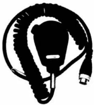
EM-48 HAND MICROPHONE
natural_image
Abstract black-and-white illustration of a stylized helmet or connector (no text or symbols)Die-cast and weather-resistant microphone. Same as the supplied one.
HS-50 HANDSET
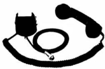
natural_image
Silhouette of a vintage telephone handset and earbell (no text or symbols)Provides better audio reception and comes in handy for listening privacy on board.
MN-100, MN-100L ANTENNA MATCHERS
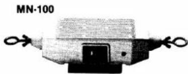
natural_image
Mechanical component labeled MN-100, showing a housing with two side handles and a central mounting bracket (no visible text or symbols)MN-100L
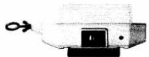
Match the IC-M600 to a long wire or whip antenna system without applying DC power. An antenna matcher is recommended for emergency situations.
PS-60 DC POWER SUPPLY
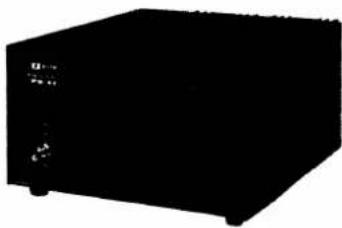
natural_image
Black rectangular electronic device with no visible text or symbols on its bodyProvides 13.6 V DC (30 A) output from a ship-equipped AC outlet or AC wall outlet.
Input voltage: 100, 117, 220 or 240 V AC
PS-66 DC-DC CONVERTER
natural_image
Pure black rectangular block with no visible text, numbers, or symbolsConverts 19\~32 V DC voltage to 13.6 V (30 A) and provides a floating ground system.
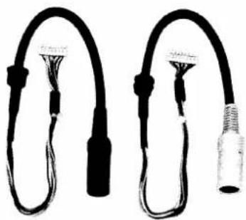
OPC-302, OPC-303 ACC CABLES
natural_image
Two black cable connectors with connectors and wires, no visible text or symbolsAllow connection of external equipment via [ACC1] and [ACC2].
Count on us!
natural_image
Black and white textured surface with no visible text, symbols, or identifiable objects
- FOREWORD
- EXPLICIT DEFINITIONS
- IMPORTANT SAFETY PRECAUTIONS
- FEATURES
- TABLE OF CONTENTS
- UNPACKING
- 1
- PANEL DESCRIPTION
- ■ Switches and controls
- ① INTERNAL SPEAKER
- ② FUNCTION DISPLAY (p. 4)
- ③ MAIN DIAL
- ④ CLARITY SWITCHES [CLAR] (pgs. 15, 16)
- ⑤ VOLUME SWITCHES [VOL] (p. 15)
- ⑥ POWER SWITCHES [POW]
- ⑦ FUNCTION SWITCH [FUNC] (pgs. 15, 16)
- ⑧ RECEIVE FREQUENCY ENTER SWITCH [RX]
- ⑨ TRANSMIT FREQUENCY ENTER SWITCH [TX]
- ⑩ KEYBOARD
- ⑪ TRANSMIT FREQUENCY CHECK SWITCH [TXF]
- ⑫ CLEAR SWITCH [CE]
- ⑬ 2182 kHz SWITCH [2182] (p. 11)
- ⑭ MODE SWITCH [MODE]
- ⑮ ALARM SWITCH [ALM] (p. 19)
- ⑯ ANTENNA TUNER SWITCH [TUNE]
- PANEL DESCRIPTION
- Rear panel
- ① ANTENNA CONNECTOR [ANT] (p. 8)
- ② SPARE HOLES [ACC1], [ACC2] (p. 10)
- ③ ANTENNA TUNER CONNECTOR [TUNER] (p. 9)
- ④ DC POWER CONNECTOR [DC 13.6 V] (pgs. 6, 8)
- ⑤ MIC CONNECTOR [MIC]
- ⑥ EXTERNAL SPEAKER JACK [EXT SP]
- ⑦ GROUND TERMINAL [GND] (p. 8)
- ■ Function display
- ① CHANNEL INDICATOR
- ② DUPLEX INDICATOR
- ③ SIMPLEX INDICATOR
- ④ MODE INDICATORS
- ⑤ CLARITY INDICATOR
- ⑥ FUNCTION INDICATOR
- ⑦ NOISE BLANKER INDICATOR
- ⑧ AGC OFF INDICATOR
- ⑨ SQUELCH INDICATOR
- ⑩ SPEAKER-OFF INDICATOR
- ⑪ S/RF INDICATOR
- ⑫ FREQUENCY READOUT
- ⑬ ALARM INDICATOR
- ⑭ FREQUENCY SETTING INDICATOR
- ⑮ TUNING INDICATOR
- TRANSMIT INDICATOR
- ⑰ RECEIVE INDICATOR
- INSTALLATION
- ■ Mounting the transceiver
- Rear panel connections
- DC power cable
- Ground cable
- Antenna coaxial cable
- Microphone
- ■ Installation example
- IC-M600 installation
- Optional AT-120E installation
- DC power source
- Antenna
- Ground
- Ground connections
- Antenna connections
- Power source
- • DC power cable connection
- 3
- EXTERNAL EQUIPMENT CONNECTIONS
- ■ AT-120E HF AUTOMATIC ANTENNA TUNER
- ■Internal setting for a non-lcom antenna tuner
- MN-100, MN-100L ANTENNA MATCHERS
- ■ OPC-302, OPC-303 ACC CABLES
- 4
- SELECTING A CHANNEL
- ■ Direct selection of 2182 kHz
- ■ Selecting a memory channel
- Using the keyboard
- Using the main dial
- SETTING A FREQUENCY
- ■ Setting a receive frequency
- ■ Setting a transmit frequency
- ■ Changing the frequency in 100 Hz steps
- OPERATING RULES AND GUIDELINES
- Call procedures
- Priorities
- Privacy
- Logs
- Radio licenses
- SHIP STATION LICENSE
- OPERATOR'S LICENSE
- 7
- RECEIVING
- ■ Receiving
- ■Adjusting the RF gain
- • Using the noise blanker function
- • Using the squelch function
- - Receive indicator
- • Using the AGC switch
- • Using the dimmer switch
- - Adjusting the clarity
- • Using the speaker-off switch
- 8
- TRANSMITTING
- ■Transmitting
- ■ Setting the transmit power
- ■ Programming a frequency
- ■ Changing the operating mode
- ■ Clearing memory information
- ALARM SIGNAL
- ■Transmitting an alarm signal on 2182 kHz
- Distress call procedures
- ■ Testing an alarm signal
- CROSS CHANNEL OPERATION
- ■ Cross channel operation
- MAINTENANCE
- ■ Replacing a fuse
- Cleaning
- ACC cables
- SPECIFICATIONS
- GENERAL
- TRANSMITTER
- RECEIVER
Marke : ICOM
Modell : ICM600
Kategorie : Walkie-Talkie