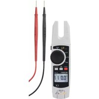
VC1113 - Multimeter VOLTCRAFT - Kostenlose Bedienungsanleitung
Finden Sie kostenlos die Bedienungsanleitung des Geräts VC1113 VOLTCRAFT als PDF.



| Produkttyp | Digitalmultimeter mit Stromzange |
| Marke | Voltcraft |
| Modell | VC1113 |
| Kategorie | Multimeter |
| Abmessungen (L x B x H) | Ca. 200 x 70 x 35 mm |
| Gewicht | Ca. 300 g |
| Stromversorgung | 2 AAA-Batterien 1,5 V |
| Display | LCD-Display mit Hintergrundbeleuchtung, 6000 Counts |
| Messfunktionen | AC/DC-Spannung, AC-Strom (Zange), Widerstand, Durchgang, Diode, Kapazität, Frequenz |
| AC-Spannungsbereich | 600 V |
| AC-Strombereich (Zange) | 600 A |
| Sicherheit | CAT III 600 V, doppelte Isolierung |
| Sonderfunktionen | Datenhaltefunktion (Data Hold), automatische Abschaltung, Dioden- und Durchgangsprüfung mit akustischem Signal |
| Pflege | Mit einem trockenen, weichen Tuch reinigen. Keine Lösungsmittel verwenden. |
| Reparierbarkeit | Durch Fachpersonal reparierbar. Ersatzteile auf Anfrage erhältlich. |
| Lieferumfang | Multimeter, Batterien, Messleitungen, Stromzange, Bedienungsanleitung |
Häufig gestellte Fragen - VC1113 VOLTCRAFT
Benutzerfragen zu VC1113 VOLTCRAFT
0 Frage zu diesem Gerät. Beantworten Sie die, die Sie kennen, oder stellen Sie Ihre eigene.
Eine neue Frage zu diesem Gerät stellen
Laden Sie die Anleitung für Ihr Multimeter kostenlos im PDF-Format! Finden Sie Ihr Handbuch VC1113 - VOLTCRAFT und nehmen Sie Ihr elektronisches Gerät wieder in die Hand. Auf dieser Seite sind alle Dokumente veröffentlicht, die für die Verwendung Ihres Geräts notwendig sind. VC1113 von der Marke VOLTCRAFT.
BEDIENUNGSANLEITUNG VC1113 VOLTCRAFT
D Bedienungsanleitung
Stromzange
Best.-Nr. 2274366
Seite 2 - 31
a) Symbole in dieser Bedienungsanleitung ....4
b) Symbole am Produkt....5
-
Bestimmungsgemäße Verwendung 6
-
Lieferumfang ....7
- Merkmale und Funktionen....7
- Sicherheitshinweise....8
a) Allgemein....8
b) Angeschlossene Geräte....9
c) Batterien....9
d) Personen und Produkt......9
- Bedienelemente und Symbole 11
a) Stromzange....11
b) Symbole im LC-Display....12
- Einlegen/Wechseln der Batterien 13
a) Batterien einlegen ....13
b) Batterien wechseln....14
- Messbetrieb....14
a) Ein-/Ausschalten / Messfunktion wählen....15
b) Relative Messung....16
c) Strommessung „A“ 16
d) Spannungsmessung „V“......19
e) Widerstandsmessung....21
f) Durchgangsprüfung....22
g) Diodentest....23
h) Kapazitätsmessung....23
i) Berührungslose Wechselspannungsdetektion „NCV“ 24
- Zusatzfunktionen....25
a) Automatische Abschaltung....25
b) Beleuchtung 26
c) HOLD-Funktion 26
d) Taschenlampenfunktion....26
-
Wartung....27
-
Pflege und Reinigung....27
-
Entsorgung....28
a) Produkt....28
b) Batterien....28
- Technische Daten....28
a) Stromzange....28
b) Messtoleranzen....29
1. Einführung
Sehr geehrte Kundin, sehr geehrter Kunde,
wir bedanken uns für den Kauf dieses Produkts.
Dieses Produkt entspricht den gesetzlichen, nationalen und europäischen Anforderungen.
Um diesen Zustand zu erhalten und einen gefahrlosen Betrieb sicherzustellen, müssen Sie als Anwender diese Bedienungsanleitung beachten!

Diese Bedienungsanleitung gehört zu diesem Produkt. Sie enthält wichtige Hinweise zur Inbetriebnahme und Handhabung. Achten Sie hierauf, auch wenn Sie dieses Produkt an Dritte weitergeben. Heben Sie deshalb diese Bedienungsanleitung zum Nachlesen auf!
Bei technischen Fragen wenden Sie sich bitte an:
Deutschland: www.conrad.de
Österreich: www.conrad.at
Schweiz: ____ www.conrad.ch
2. Symbol-Erklärung
a) Symbole in dieser Bedienungsanleitung
Das Symbol mit dem Blitz im Dreieck wird verwendet, wenn Gefahr für Ihre Gesundheit besteht, z.B. durch einen elektrischen Schlag.

Das Symbol mit dem Ausrufezeichen im Dreieck weist auf wichtige Hinweise in dieser Bedienungsanleitung hin, die unbedingt zu beachten sind.
Das Pfeil-Symbol ist zu finden, wenn Ihnen besondere Tipps und Hinweise zur Bedienung gegeben werden sollen.
b) Symbole am Produkt
Symbol Bedeutung
| Dieses Symbol zeigt an, dass dieses Produkt nach Schutzklasse II aufgebaut ist. Es besitzt eine verstärkte oder doppelte Isolierung zwischen Netzstromkreis und Ausgangsspannung. | |
| ≡ | Erdpotential |
| ⚠️ | Das Symbol mit dem Ausrufezeichen im Dreieck wird verwendet, wenn Gefahr für Ihre Gesundheit besteht, z.B. durch einen elektrischen Schlag. |
| ~ | Wechselspannung |
| --- | Gleichspannung |
| -■ | Akustische Signale ein/aus |
| ▶+ | Diode |
| +← | Symbol für den Kapazitätsmessbereich |
| Ein Blitzsymbol im Quadrat erlaubt die Strommessung an unisolierten, gefährlichen/aktiven Stromleitern und warnt vor den möglichen Gefahren. Die persönliche Schutzausrüstung ist anzuwenden. | |
| CE | Dieses Gerät ist CE-konform und erfüllt die erforderlichen europäischen Richtlinien. |
| CAT II | Messkategorie II für Messungen an elektrischen und elektronischen Geräten, welche über einen Netzstecker direkt mit Netzspannung versorgt werden. Diese Kategorie umfasst auch alle kleineren Kategorien (z.B. CAT I zur Messung von Signal- und Steuerspannungen). |
| CAT III | Messkategorie III für Messungen in der Gebäudeinstallation (z.B. Steckdosen oder Unterverteilungen). Diese Kategorie umfasst auch alle kleineren Kategorien (z.B. CAT II zur Messung an Elektrogeräten). Der Messbetrieb in CAT III ist nur mit Messspitzen mit einer maximalen freien Kontaktlänge von 4 mm bzw. mit Abdeckkappen über den Messspitzen zulässig. |
| Polaritätsmarkierung (Pluspol) für Gleichstrommessung. Das Symbol zeigt die Stromflussrichtung an, um polungsrichtig messen zu können. |
Positionsmarkierung für den Stromleiter für korrekte Strommessung.
3. Bestimmungsgemäße Verwendung
Das Produkt dient zum Messen und Anzeigen der elektrischen Größen im Bereich der Überspannungskategorie CAT II bis max. 1000 V und CAT III bis max. 600 V gegen Erdpotential, gemäß EN 61010-1, EN 61010-2-032, EN 61010-2-033 und allen niedrigeren Kategorien.
- Messen von Gleich- und Wechselspannung bis max. 1000 V/DC, 750 V/AC
- Messen von Gleich- und Wechselströmen bis max. 200 A
- Messen von Widerständen
- Durchgangsprüfung (<10 Ω akustisch)
- Diodentest
- Messen von Kapazitäten bis 6 mF
- Berührungslose Wechselspannungsprüfung (NCV) ≥100 V rms Entfernung ≤10 mm
- ≥100 - 600 V/AC und ≤15 mm Abstand
- Die Spannung im Strom-Messkreis darf 1000 V in CAT II bzw. 600 V in CAT III nicht überschreiten.
Messungen unter widrigen Umgebungsbedingungen sind nicht zulässig. Widrige Umgebungsbedingungen sind:
- Nässe oder hohe Luftfeuchtigkeit
- Staub und brennbare Gase
- Dämpfe oder Lösungsmittel
- sowie Gewitter bzw. Gewitterbedingungen wie starke elektrostatische Felder usw.
Verwenden Sie zum Messen nur Prüfleiter, welche auf die Spezifikationen des Messgerätes abgestimmt sind.
Der Betrieb ist nur mit dem angegebenen Batterietyp zulässig.
Das Messgerät darf im geöffneten Zustand, mit geöffnetem Batteriefach oder fehlendem Batteriedeckel nicht betrieben werden.
Eine Verwendung ist nur in geschlossenen Räumen, also nicht im Freien erlaubt. Der Kontakt mit Feuchtigkeit, z.B. im Badezimmer u.ä. ist unbedingt zu vermeiden.
Aus Sicherheits- und Zulassungsgründen dürfen Sie das Produkt nicht umbauen und/oder verändern. Falls Sie das Produkt für andere Zwecke verwenden, als zuvor beschrieben, kann das Produkt beschädigt werden. Außerdem kann eine unsachgemäße Verwendung Gefahren wie z.B. Kurzschluss, Brand, Stromschlag, etc. hervorrufen. Lesen Sie sich die Bedienungsanleitung genau durch und bewahren Sie diese auf. Reichen Sie das Produkt nur zusammen mit der Bedienungsanleitung an dritte Personen weiter.
Alle enthaltenen Firmennamen und Produktbezeichnungen sind Warenzeichen der jeweiligen Inhaber. Alle Rechte vorbehalten.
4. Lieferumfang
- Stromzange
- Prüfleiter (1 Paar)
- 2 x AA Batterie
- Tragetasche
- Bedienungsanleitung
Aktuelle Bedienungsanleitungen
Laden Sie aktuelle Bedienungsanleitungen über den Link www.conrad.com/downloads herunter oder scannen Sie den abgebildeten QR-Code. Befolgen Sie die Anweisungen auf der Webseite.
5. Merkmale und Funktionen
• CAT II 1000V, CAT III 600V Messungen
• True RMS (Effektivwertfunktion)
• Automatische Messbereichswahl
- Hintergrundbeleuchtung
• Strombereich max. 200 A
- Berührungslose Wechselspannungsprüfung (NCV)
- Anzeige der Messbereichsüberschreitung „OL“
- Funktion zum Festhalten der Messanzeige
- Nullabgleich
6. Sicherheitshinweise
Lesen Sie sich die Bedienungsanleitung aufmerksam durch und beachten Sie insbesondere die Sicherheitshinweise. Falls Sie die Sicherheitshinweise und die Angaben zur sachgemäßen Handhabung in dieser Bedienungsanleitung nicht befolgen, übernehmen wir für dadurch resultierende Personen-/Sachschäden keine Haftung. Außerdem erlischt in solchen Fällen die Gewährleistung/Garantie.
a) Allgemein
- Das Produkt ist kein Spielzeug. Halten Sie es von Kindern und Haustieren fern.
- Lassen Sie das Verpackungsmaterial nicht achtlos liegen. Dieses könnte für Kinder zu einem gefährlichen Spielzeug werden.
- Schützen Sie das Produkt vor extremen Temperaturen, direktem Sonnenlicht, starken Erschütterungen, hoher Feuchtigkeit, Nässe, brennbaren Gasen, Dämpfen und Lösungsmitteln.
-
Wenn kein sicherer Betrieb mehr möglich ist, nehmen Sie das Produkt außer Betrieb und schützen Sie es vor unbeabsichtigter Verwendung. Der sichere Betrieb ist nicht mehr gewährleistet, wenn das Produkt:
-
sichtbare Schäden aufweist,
- nicht mehr ordnungsgemäß funktioniert,
- über einen längeren Zeitraum unter ungünstigen Umgebungsbedingungen gelagert wurde oder
- erheblichen Transportbelastungen ausgesetzt wurde.
- Gehen Sie vorsichtig mit dem Produkt um. Durch Stöße, Schläge oder dem Fall aus bereits geringer Höhe wird es beschädigt.
- Wenden Sie sich an eine Fachkraft, wenn Sie Zweifel über die Arbeitsweise, die Sicherheit oder den Anschluss des Produktes haben.
- Lassen Sie Wartungs-, Anpassungs- und Reparaturarbeiten ausschließlich von einem Fachmann bzw. einer Fachwerkstatt durchführen.
- Sollten Sie noch Fragen haben, die in dieser Bedienungsanleitung nicht beantwortet werden, wenden Sie sich an unseren technischen Kundendienst oder an andere Fachleute.
b) Angeschlossene Geräte
- Beachten Sie auch die Sicherheitshinweise und Bedienungsanleitungen der übrigen Geräte, an die das Produkt angeschlossen wird.
c) Batterien
- Achten Sie beim Einlegen der Batterien auf die richtige Polung.
- Entfernen Sie die Batterien, wenn Sie das Gerät längere Zeit nicht verwenden, um Beschädigungen durch Auslaufen zu vermeiden. Auslaufende oder beschädigte Batterien können bei Hautkontakt Säureverätzungen hervorrufen. Beim Umgang mit beschädigten Batterien sollten Sie daher Schutzhandschuhe tragen.
- Bewahren Sie Batterien außerhalb der Reichweite von Kindern auf. Lassen Sie Batterien nicht frei herumliegen, da diese von Kindern oder Haustieren verschluckt werden könnten.
- Alle Batterien sollten zum gleichen Zeitpunkt ersetzt werden. Das Mischen von alten und neuen Batterien im Gerät kann zum Auslaufen der Batterien und zur Beschädigung des Geräts führen.
- Nehmen Sie keine Batterien auseinander, schließen Sie sie nicht kurz und werfen Sie sie nicht ins Feuer. Versuchen Sie niemals, nicht aufladbare Batterien aufzuladen. Es besteht Explosionsgefahr!
d) Personen und Produkt
- Verwenden Sie das Produkt niemals gleich dann, wenn es von einem kalten in einen warmen Raum gebracht wird. Das dabei entstehende Kondenswasser kann unter Umständen das Produkt zerstören. Lassen Sie das Produkt zuerst auf Zimmertemperatur kommen, bevor es angeschlossen und verwendet wird. Dies kann u.U. mehrere Stunden dauern.
- Gießen Sie nie Flüssigkeiten über elektrischen Geräten aus und stellen Sie keine mit Flüssigkeit gefüllten Gegenstände neben das Gerät.
- Verwenden Sie das Gerät nicht, wenn das Gerät oder die Prüfleiter einen beschädigten Eindruck machen oder wenn Sie vermuten, dass das Gerät nicht ordnungsgemäß funktioniert. Achten Sie insbesondere auf die Isolierung. Führen Sie auf keinen Fall Messungen durch, wenn die Schutzisolierung beschädigt (eingerissen, abgerissen usw.) ist. Ersetzen Sie die Messleitung, falls die Isolationsschicht beschädigt ist.
-
Der Drehschalter sollte zum Messen auf eine eindeutige Position eingestellt werden.
-
Verwenden Sie zum Messen nur die mitgelieferten Prüfleiter, da diese auf die Spezifikationen des Messgerätes abgestimmt sind.
- In Schulen und Ausbildungseinrichtungen, Hobby- und Selbsthilfewerkstätten ist der Umgang mit Messgeräten durch geschultes Personal verantwortlich zu überwachen.
- In gewerblichen Einrichtungen sind die Unfallverhütungsvorschriften des Verbandes der gewerblichen Berufsgenossenschaften für elektrische Anlagen und Betriebsmittel zu beachten.
- Das Produkt ist nur für den Betrieb in trockener Umgebung geeignet. Das gesamte Produkt darf nicht feucht oder nass werden. Fassen Sie es niemals mit nassen Händen an, um es nicht zu beschädigen.
- Überprüfen Sie vor jeder Messung das Messgerät und die Prüfleiter auf Beschädigungen.
- Stellen Sie das Messgerät vor jeder Messung auf die gewünschte Einheit. Eine falsche Messung könnte das Produkt zerstören!
• Die Spannung zwischen den Anschlusspunkten darf die angegebene Spannung nicht überschreiten. - Vor jedem Wechsel des Messbereiches sind die Messspitzen vom Messobjekt zu entfernen.
- Seien Sie besonders vorsichtig beim Umgang mit Spannungen >33 V Wechsel-(AC) bzw. >42 V Gleichspannung (DC)! Bereits bei diesen Spannungen können Sie bei Berührung elektrischer Leiter einen lebensgefährlichen elektrischen Schlag erhalten.
- Um einen elektrischen Schlag zu vermeiden, achten Sie darauf, dass Sie die zu messenden Anschlüsse/Messpunkte während der Messung nicht, auch nicht indirekt, berühren.
- Über die fühlbaren Griffbereichsmarkierungen an den Messspitzen und am Messgerät darf während des Messens nicht gegriffen werden.
- Vermeiden Sie den Betrieb in unmittelbarer Nähe von:
- Starken magnetischen oder elektromagnetischen Feldern
- Sendeantennen oder HF-Generatoren.
- Achten Sie bei jeder Messung darauf, dass durch den Stromzangen-Sensor keine Gegenstände wie z.B. Kabel gequetscht werden.
- Achten Sie beim Anschluss der Prüfleiter an das Messgerät immer auf die korrekte Polarität. (Rot = Pluspol, Schwarz = Minuspol).
- Beachten Sie bei jeder Messung die Beschreibung der Abbildungen in jedem Kapitel. Eine falsche Messung könnte das Produkt zerstören.
- Entfernen Sie vor dem Anschluss der Prüfleiter die Staubschutzkappen von den Anschlusssteckern der Prüfleiter. Montieren Sie diese stets nach jeder Messung, um eine Verschmutzung der Kontakte zu vermeiden.
- Beachten Sie auch die Sicherheitshinweise in den einzelnen Kapiteln.
- Verwenden sie das Messgerät niemals ohne die Abdeckungen auf der Rückseite oder des Batteriefachs. Es besteht die Gefahr eines elektrischen Schlages.
7. Bedienelemente und Symbole
a) Stromzange
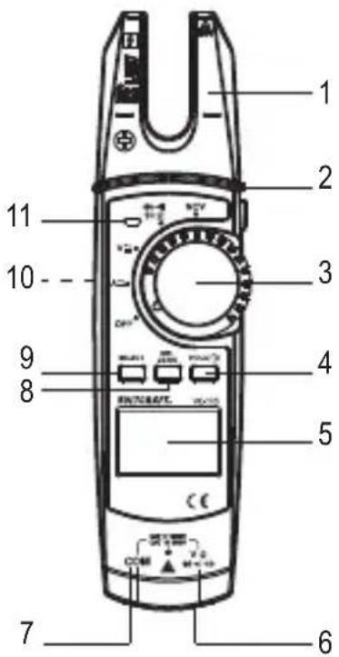
1 Stromzange
2 Taschenlampen-Taste
3 Drehschalter zur Messfunktionswahl
4 Taste HOLD/
5 LC-Display
6 V-Messbuchse ( √←Ω)
7 COM-Messbuchse
8 Taste REL ZERO
9 Taste SELECT
10 Batteriefach (Rückseite)
11 NCV-Signalanzeige
b) Symbole im LC-Display
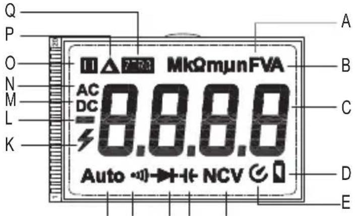
Nr. Symbol Erklärung
| A Ω | Ohm (Einheit des elektrischen Widerstandes) | |
| kΩ, MΩ | Kilo-Ohm (exp.3), Mega-Ohm (exp.6) | |
| Hz | Hertz (Einheit der elektrischen Frequenz) | |
| mV | Milli-Volt (exp.-3) | |
| mA, μA | Milli-Ampere (exp.-3), Micro-Ampere (exp.-6) | |
| nF | Nano-Farad (exp.-9; Einheit der elektrischen Kapazität) | |
| μF | Mikro-Farad (exp.-6) | |
| mF | Milli-Farad (exp.-3) |
| B VA Volt (Einheit der elektrischen Spannung) |
| Ampere (Einheit der elektrischen Stromstärke) |
C - Messwert-Anzeige
D Batteriekapazität
E Automatische Abschaltung
F NCV Berührungslose Wechselspannungserkennung
G Symbol für Kapazität
H Symbol für den Diodentest
I ·) Symbol für den akustischen Durchgangsprüfer
J Auto Automatische Messbereichswahl ist aktiv
Nr. Symbol Erklärung
K Blitzsymbol zur Spannungsmessung
L + - Anzeige des Vorzeichens des Messwerts
M DC Gleichspannung/-strom
N AC Wechselspannung/-strom
O HOLD-Funktion ist aktiv, wenn das Symbol angezeigt wird
P Relativmeasung ist eingestellt
Q Nullstel ZERO
8. Einlegen/Wechseln der Batterien
a) Batterien einlegen
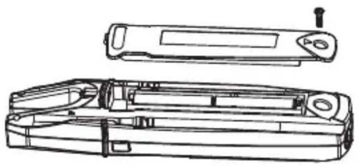
Bei Anlieferung des Produktes sind üblicherweise keine Batterien eingesetzt. Der Gebrauch von Akkus ist wegen der niedrigeren Spannung nicht empfohlen.
Befolgen Sie die nachstehenden Schritte, um das Produkt in Betrieb zu nehmen.
- Bringen Sie den Drehschalter (3) in Position OFF. Trennen Sie die Stromzange von jeglichen Messobjekten.
- Drehen Sie das Produkt um und legen es auf eine weiche Oberfläche, welche die Anzeige vor Kratzern schützt.
- Lösen Sie mit einem passenden Kreuzschlitzschraubendreher die Verschlussschraube der Batteriefachabdeckung (10). Entfernen Sie die Batteriefachabdeckung.
- Entnehmen Sie die verbrauchten Batterien und entsorgen Sie diese umweltgerecht. Beachten Sie das Kapitel „13. Entsorgung“.
- Legen Sie zwei neue 1,5 V Batterien des Typs AA, unter Beachtung der aufgedruckten Polaritätsangaben, in die Batteriemulden ein (2 x AA Batterien sind im Lieferumfang diese Produkts enthalten).
- Setzen Sie die Batteriefachabdeckung auf (Lasche beachten) und schrauben sie Sie mit der Schraube fest. Wenden Sie beim Festziehen der Schraube keine Gewalt an.
b) Batterien wechseln
Ein Batteriewechsel ist erforderlich, wenn im LC-Display (5) das Symbol ☐(D) aufleuchtet oder die Hintergrundbeleuchtung nur noch schwach oder gar nicht mehr leuchtet. Ersetzen Sie die Batterien möglichst bald wie im Abschnitt „a) Batterien einlegen“ beschrieben. Leuchtet nach dem Einschalten nur das Symbol ☐auf, ersetzen Sie sofort die Batterien.
9. Messbetrieb
Überschreiten Sie auf keinen Fall die max. zulässigen Eingangsgrößen. Berühren Sie keine Schaltungen oder Schaltungsteile, wenn darin höhere Spannungen als 33 V/AC rms oder 42 V/DC anliegen können! Lebensgefahr!

Die max. zulässige Spannung im Strommesskreis gegen Erdpotential darf 1000 V in CAT II und 600 V in CAT III nicht überschreiten.
Kontrollieren Sie vor Messbeginn die angeschlossenen Prüfleiter auf Beschädigungen wie z.B. Schnitte, Risse oder Quetschungen. Defekte Prüfleiter dürfen nicht mehr benutzt werden! Lebensgefahr!
Über die fühlbaren Griffbereichsmarkierungen an den Messspitzen darf während des Messens nicht gegriffen werden.
Es dürfen immer nur die zwei Prüfleiter am Messgerät angeschlossen welche zum Messbetrieb benötigt werden. Entfernen Sie aus Sicherheitsgründen alle nicht benötigten Prüfleiter vom Messgerät, wenn Sie eine Strommessung durchführen.
Messungen in Stromkreisen >33 V/AC und >42 V/DC dürfen nur von Fachkräften und eingewiesenen Personen durchgeführt werden, die mit den einschlägigen Vorschriften und den daraus resultierenden Gefahren vertraut sind.
Beachten Sie die erforderlichen Sicherheitshinweise, Vorschriften und Schutzmaßnahmen zur Eigensicherung.
Die Messwerte werden in der LC-Display (5) der Stromzange dargestellt. Die Polarität wird bei negativem Messwert automatisch mit Vorzeichen (-) dargestellt.
→ Sobald < OL > (für „Overload“ = Überlauf) im LC-Display (5) erscheint, haben Sie den Messbereich überschritten.
Auf den Steckern der beiliegenden Prüfleiter befinden sich Transportschutzkappen. Entfernen Sie diese, bevor Sie die Stecker in die Anschlussbuchsen des Messgeräts stecken.
a) Ein-/Ausschalten / Messfunktion wählen
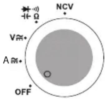
- Schalten Sie den Drehschalter (3) aus der Position OFF auf eine Messfunktion. Das Messgerät schaltet ein. Ein Bestätigungston ertönt.
- Das Produkt ist ausgeschaltet, wenn der Drehschalter (3) in der Position OFF steht. Schalten Sie das Produkt nach Beenden des Messvorgangs aus.
-
Wählen Sie die einzelnen Messfunktionen über den Drehschalter an. Die automatische Bereichswahl ist in einigen Messfunktionen aktiv. Hierbei wird immer der jeweils passende Messbereich eingestellt. In der LC-Display (5) erscheint „Auto“ (J).
-
Einige Messfunktionen müssen mit Hilfe der Taste SELECT (9) eingestellt werden. Lesen Sie dazu in den entsprechenden Kapiteln.
Wichtig! Stellen Sie vor jeder Messung sicher, dass Sie die richtige Messfunktion eingestellt haben. - Bei Betätigung einer Taste bzw. des Drehschalters ertönt ein Piepton, wenn ein Schaltvorgang gültig war. Bei einer ungültigen Operation, gibt der Summer zwei Töne ab.
b) Relative Messung
Sie können Messwerte absolut messen (normaler Messmodus) oder einen Wert in Beziehung zum vorhergehenden messen.
- Um einen aktuell erfassten Messwert als Ausgangswert (Nullwert) zu übernehmen, drücken Sie im normalen Messmodus während einer Messung die Taste REL ZER (8). Die Displayanzeige wechselt zu „000“. „REL“ und 🔒 werden im LC-Display (5) angezeigt.
- Um in den normalen Messmodus zurück zu schalten, drücken Sie die Taste REL ZERO (8) erneut. Wenn Sie den Drehschalter (3) auf eine andere Messfunktion stellen, kehrt das Messgerät gleichfalls in den normalen Messmodus zurück.
- Sie können die HOLD-Funktion in gleicher Weise bei Relativmessungen verwenden. Eine aktive HOLD-Funktion wird abgeschaltet, wenn Sie von der Relativmessung in den Normalmodus umschalten.
c) Strommessung „A“
Die Strommessung erfolgt berührungslos über die Stromzange (1). Die Sensoren in der Stromzange erfassen das Magnetfeld, das von stromdurchflossenen Stromleitern umgeben ist.
→ Achten Sie darauf, dass der Stromleiter immer richtig ausgerichtet durch die Stromzange verläuft (Linien-Hilfsmarkierungen beachten).
Umgreifen Sie mit der Stromzange immer nur einen Stromleiter.
Messen von Wechselstrom A ≈
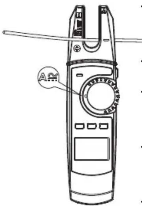
- Schalten Sie das Produkt am Drehschalter (3) ein und wählen den Messbereich A —Das Produkt ist im Messbereich für Wechselstrom und im LC-Display (5) erscheint „AC“ und „A“.
- Der Wechselstrom-Messbereich wird vom Messgerät automatisch gewählt.
- Führen Sie den einzelnen Stromleiter, der gemessen werden soll. Positionieren Sie den Stromleiter entlang der beiden Richtungslinien am unteren Ende der U-förmigen Stromzange.
- Der gemessene Strom wird im LC-Display angezeigt. Messen Sie keine Ströme von über 200 A. Beim Überschreiten des Messbereiches (200 A) ertönen dauernd Pieptöne.
- Entfernen Sie nach Messende die Stromzange vom Messobjekt und schalten Sie das Produkt aus.
Messen von Gleichstrom A mit Nullabgleich
Durch die hohe Empfindlichkeit und das Umgebungs-Magnetfeld (z.B. Erdmagnetfeld etc.) wird bei geschlossener Stromzange im Gleichstrom-Messbereich immer ein geringer Stromwert angezeigt. Setzen Sie die Anzeige manuell auf Null unmittelbar vor jeder Messung bzw. wenn das Stromkabel gewechselt wird. Zum Nullabgleich gehen Sie wie folgt vor:
- Schalten Sie das Produkt am Drehschalter (3) ein und wählen den Messbereich A. Das Produkt ist im Messbereich für Wechselstrom und im LC-Display (5) erscheint „AC“ und „A“.
- Drücken Sie die Taste SELECT (9), um den Messbereich für Gleichstrom zu wählen. In der Anzeige erscheint „DC“ und „A“.
- Führen Sie ohne einen Stromleiter in der Stromzange einen Nullabgleich durch. Drücken Sie dazu kurz die Taste REL ZERO (8). Ein Piepton und die Nullanzeige im LC-Display bestätigen den Nullabgleich.
- Jedes kurze Drücken der Taste REL ZERO löst einen neuen Nullabgleich aus. Zum Deaktivieren dieser Funktion halten Sie die Taste REL ZERO für ca. 2 Sekunden gedrückt. Das Symbol „ZERO“ erlischt. Sie befinden sich dann wieder im Normal-Messbetrieb ohne Nullabgleich.
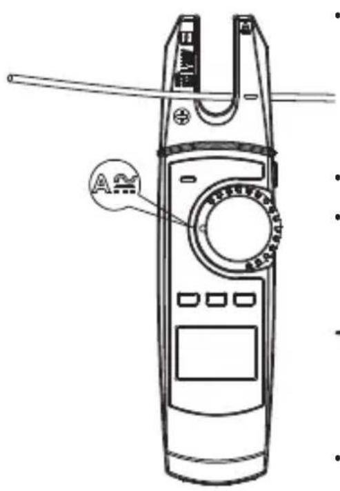
- Nach einem erfolgreichem Nullabgleich, führen Sie den einzelnen Stromleiter, der gemessen werden soll in die Stromzange ein. Positionieren Sie den Stromleiter entlang der beiden Richtungslinien am unteren Ende der U-förmigen Stromzange.
- Der gemessene Strom wird im LC-Display angezeigt.
- Entsprechend der Einlegerichtung wird ein positives oder negatives Vorzeichen zum Anzeigewert mit angezeigt.
Sobald bei der Gleichstrommessung ein Minus „-“ vor dem Messwert erscheint, verläuft der Strom entgegengesetzt (oder die Stromzange ist vertauscht).
- Messen Sie keine Ströme von über 200 A. Beim Überschreiten des Messbereiches (200 A) ertönen dauernd Pieptöne.
- Entfernen Sie nach Messende die Stromzange vom Messobjekt und schalten Sie das Produkt aus.
d) Spannungsmessung „V“
Messung von Wechselspannungen „AC“ (V)
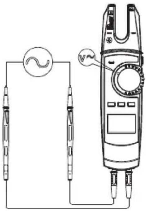
- Schalten Sie das Produkt am Drehschalter (3) ein und wählen den Messbereich V in der Anzeige erscheint „AC“ und „V“.
- Stecken Sie die rote Messleitung in die V-Messbuchse (6), die schwarze Messleitung in die COM-Messbuchse (7).
- Verbinden Sie die beiden Messspitzen mit dem Messobjekt (Generator, Netzspannung usw.).
• Der Messwert wird im LC-Display (5) angezeigt. - Messen Sie keine Spannungen von über 750 V/AC. Beim Überschreiten des Messbereiches (750 V/AC) ertönen dauerhaft Pieptöne.
→ Beim Überschreiten eine Spannung von 30 V/AC zeigt das LC-Display eine visuelle Hochspannungswarnung an, um vor der bestehenden Gefahr eines elektrischen Schlages zu warnen.
- Entfernen Sie nach Messende die Stromzange vom Messobjekt und schalten Sie das Produkt aus.
Messung von Gleichspannungen „DC“ (V 7).
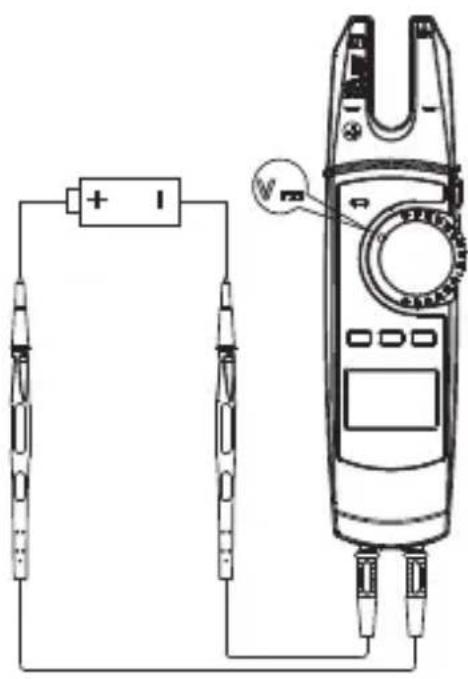
- Schalten Sie das Produkt am Drehschalter (3) ein und wählen den Messbereich V Drücken Sie die Taste SELECT (9), um den Gleichstrommessbereich zu wählen. In der Anzeige erscheinen „DC“ und „V“
- Stecken Sie die rote Messleitung in die V-Messbuchse (6), die schwarze Messleitung in die COM-Messbuchse (7).
- Verbinden Sie die beiden Messspitzen mit dem Messobjekt (Batterie, Schaltung usw.). Die rote Messspitze entspricht dem Pluspol, die schwarze Messspitze dem Minuspol.
Beim Überschreiten eine Spannung von 42 V/DC zeigt das LC-Display eine visuelle Hochspannungswarnung an, um vor der bestehenden Gefahr eines elektrischen Schlages zu warnen.
- Der aktuelle Messwert wird zusammen mit der jeweiligen Polarität im Display angezeigt.
Sobald bei der Gleichspannung ein Minus „-“ vor dem Messwert erscheint, ist die gemessene Spannung negativ (oder die Prüfleiter sind vertauscht).
- Messen Sie keine Spannungen von über 1000 V/DC. Beim Überschreiten des Messbereiches (1000 V/DC) ertönen dauerhaft Pieptöne.
- Entfernen Sie nach Messende die Stromzange vom Messobjekt und schalten Sie das Produkt aus.
e) Widerstandsmessung

Vergewissern Sie sich, dass alle zu messenden Schaltungsteile, Schaltungen und Bauelemente, z. B. Kondensatoren sowie andere Messobjekte unbedingt spannungslos und entladen sind.
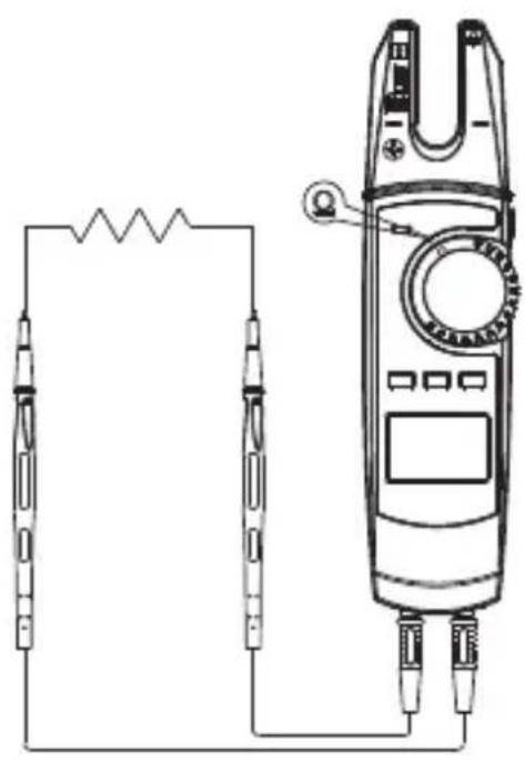
- Schalten Sie das Produkt am Drehschalter (3) ein und wählen den Messbereich ^-1 . In der Anzeige erscheinen „ “ und „V“.
- Stecken Sie die rote Messleitung in die V-Messbuchse (6), die schwarze Messleitung in die COM -Messbuchse (7).
→ Halten Sie vor dem Messen im Messbereich von 600 Ω die Messspitzen zusammen, um sie kurz zu schließen. Drücken Sie dazu die Taste REL ZERO (8), um den Anzeigewert zurückzusetzen. Dies gleicht den Einfluss des Widerstands der Messspitzen aus.
- Verbinden Sie die beiden Messspitzen mit dem Messobjekt (Bauteil, Schaltung usw.). Die rote Messspitze entspricht dem Pluspol, die schwarze Messspitze dem Minuspol.
- Der aktuelle Messwert wird zusammen mit der jeweiligen Polarität im Display angezeigt.
- Entfernen Sie nach Messende die Stromzange vom Messobjekt und schalten Sie das Produkt aus.
Wenn Sie eine Widerstandsmessung durchführen, achten Sie darauf, dass die Messpunkte, welche Sie mit den Messspitzen zum Messen berühren, frei von Schmutz, Öl, Lötlack oder ähnlichem sind. Solche Umstände können das Messergebnis verfälschen.
f) Durchgangsprüfung

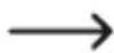
Vergewissern Sie sich, dass alle zu messenden Schaltungsteile, Schaltungen und Bauelemente sowie andere Messobjekte, z.B. Kondensatoren unbedingt spannungslos und entladen sind.
- Schalten Sie das Produkt am Drehschalter (3) ein und wählen den Messbereich
- Drücken Sie die Taste SELECT (9), um den Messbereich für die Durchgangsprüfung zu wählen. Im LC-Display erscheint
- Stecken Sie die rote Messleitung in die V-Messbuchse (6), die schwarze Messleitung in die COM -Messbuchse (7).
- Verbinden Sie die beiden Messspitzen mit dem Messobjekt (Bauteil, Schaltung usw.). Die rote Messspitze entspricht dem Pluspol, die schwarze Messspitze dem Minuspol.
- Wenn der gemessene Widerstandswert weniger als 10 Ohm beträgt, ertönt dauernd eine akustische Meldung, liegt er zwischen 10 und 100 Ohm ertönt möglicherweise ein Ton, oder auch nicht. Über 1000 Ohm wird keinerlei akustische Meldung ausgegeben.
- Entfernen Sie nach Messende die Stromzange vom Messobjekt und schalten Sie das Produkt aus.
g) Diodentest

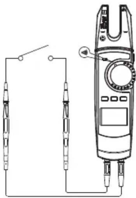
Vergewissern Sie sich, dass alle zu messenden Schaltungsteile, Schaltungen und Bauelemente sowie andere Messobjekte, z.B. Kondensatoren, unbedingt spannungslos und entladen sind.
- Schalten Sie das Produkt am Drehschalter (3) ein und wählen den Messbereich
- Drücken Sie die Taste SELECT (9), um den Messbereich für den Diodentest zu wählen. Im LC-Display erscheint
- Stecken Sie die rote Messleitung in die V-Messbuchse (6), die schwarze Messleitung in die COM -Messbuchse (7).
- Verbinden Sie die beiden Messspitzen mit dem Messobjekt (Bauteil, Schaltung usw.). Die rote Messspitze entspricht dem Pluspol, die schwarze Messspitze dem Minuspol. Beachten Sie die Polarität.
- Eine positive Spannung wird im LC-Display (5) angezeigt. Haben Sie die Polarität der Messpitzen vertauscht erscheint die Anzeige „OL“.
- Entfernen Sie nach Messende die Stromzange vom Messobjekt und schalten Sie das Produkt aus.
Um genaueste Messergebnisse zu erhalten, empfiehlt es sich Bauteile aus den Schaltungen zu entfernen.
h) Kapazitätsmessung

Vergewissern Sie sich, dass alle zu messenden Schaltungsteile, Schaltungen und Bauelemente sowie andere Messobjekte unbedingt spannungslos und entladen sind.
Beachten Sie bei Elektrolyt-Kondensatoren unbedingt die Polarität.
Es empfiehlt sich bei Kapazitätsmessungen im Bereich von 60 nF einen Nullabgleich durchzuführen, um den Widerstand der Prüfleiter zu kompensieren. Drücken Sie dazu kurz die Taste REL ZERO (8).
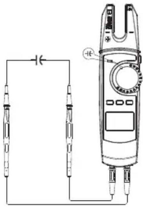
- Schalten Sie das Produkt am Drehschalter (3) ein und wählen den Messbereich
- Drücken Sie die Taste SELECT (9), um den Messbereich für den Kapazitätsmessung zu wählen. Im LC-Display erscheint
- Stecken Sie die rote Messleitung in die V-Messbuchse (6), die schwarze Messleitung in die COM -Messbuchse (7).
- Verbinden Sie die beiden Messspitzen mit dem zu messenden Kondensator. Die rote Messspitze entspricht dem Pluspol, die schwarze Messspitze dem Minuspol. Beachten Sie die Polarität. Im Display wird nach einer kurzen Zeit die Kapazität angezeigt. Warten Sie, bis sich die Anzeige stabilisiert hat.
- Sobald
- (für Overload = Überlauf) im LC-Display erscheint, haben Sie den Messbereich überschritten bzw. der Messkreis ist unterbrochen.
- Schalten Sie das Produkt am Drehschalter (3) ein und stellen Sie den Drehschalter (3) auf Position NCV.
- Führen Sie den Magnetfeld-(NCV)-Sensor an der rechten Seite der Stromzange so nah wie möglich an einen Leiter. Der Abstand sollte bis ca.10 mm betragen.
- Solange keine Wechselspannung erkannt wird, wird „EF" im LC-Display angezeigt.
- Wenn eine Wechselspannung von ≥100 V/AC rms bei einer Messentfernung von <10 mm erkannt wird, beginnen Alarmtöne zu ertönen und die NCV-Signalanzeige (11) beginnt schnell zu flackern.
- Entsprechend der detektierten Wechselspannung wird die Stärke der erkannten Spannung über 4 Strichsymbole angezeigt „—“, „—“, „—“ oder „———“. Die Stärke der erkannten Spannung steigt mit der Anzahl der Striche.
- Entfernen Sie nach Messende die Stromzange vom Messobjekt und schalten Sie das Produkt aus.
- Für eine bessere Ablesbarkeit des LC-Displays (5) ist die Stromzange mit einer Hintergrundbeleuchtung ausgestattet.
- Schalten Sie die Hintergrundbeleuchtung ein, indem Sie die Taste HOLD/ ⚙ (4) drücken und für ca. 2 Sekunden festhalten, um in die Beleuchtung mit niedriger Intensität zu schalten.
- Drücken und halten Sie die Taste HOLD/☀ erneut, um in die Beleuchtung mit hoher Lichtstärke weiter zu schalten.
- Drücken und halten Sie die Taste HOLD/ für eine drittes Mal, um die Beleuchtung wieder auszuschalten. Der Schaltzyklus der Beleuchtung ist beendet.
- Die HOLD-Funktion hält den momentan gemessenen Messwert im LC-Display (5) fest, um diesen in Ruhe ablesen oder protokollieren zu können.
- Zum Einschalten der HOLD-Funktion drücken Sie die Taste HOLD/○ (4); ein Signalton bestätigt diese Aktion und es wird ○(O) im Display angezeigt.
- Um die HOLD-Funktion abzuschalten, drücken Sie die Taste HOLD/ erneut; oder betätigen den Drehschalter (3) oder wechseln Sie die Messfunktion durch Drücken der Taste SELECT (9).
- Drücken Sie die Taste (2), um die LED-Taschenlampe auf der Rückseite des Messgeräts einzuschalten.
- Drücken Sie die Taste (2), um die LED-Taschenlampe auf der Rückseite des Messgeräts auszuschalten.
- Verwenden Sie zur Reinigung keine scheuernden Reinigungsmittel, Benzine, Alkohole oder ähnliches. Dadurch wird die Oberfläche angegriffen. Verwenden Sie zur Reinigung auch keine scharfkantigen Werkzeuge, Schraubendreher oder Metallbürsten.
- Reinigen Sie die Stromzange und die Prüfleiter immer mit einem sauberen, fusselfreien, antistatischen und leicht feuchten Tuch. Lassen Sie das Gerät komplett trocknen, bevor Sie es für den nächsten Messeinsatz verwenden.
- Introduction....34
- Description of symbols ....34
-
Intended use....36
-
Package contents....37
- Features and functions....37
- Safety information ....38
- Controls and symbols....41
- Inserting/changing the batteries ....43
- Measuring mode....44
- Additional functions ....55
-
Maintenance....57
-
Care and cleaning ....57
-
Disposal....58
- Technical data ....58
- Measurement of direct and alternating voltages up to 1,000 V/DC, 750 V/AC
- Measurement of direct and alternating currents up to a maximum of 200 A
- Measurement of resistance
- Continuity testing (<10 Ω acoustic)
- Diode testing
- Measurement of capacitance up to 6 mF
- Non-contact AC voltage testing (NCV) ≥100 V RMS distance ≤10 mm
- ≥100 - 600 V/AC and ≤15 mm distance
- The voltage in the measuring circuit must not exceed 1000 V in CAT II and 600 V in CAT III.
- Moisture or high humidity
- Dust and flammable gases
- Vapours or solvents
- Thunderstorms or similar conditions such as strong electrostatic fields, etc.
- Current clamp
- Test lead (1 pair)
- 2x AA battery
- Carrying case
- The device is not a toy. Keep it out of the reach of children and pets.
- Do not leave packaging material lying around carelessly. It may become a dangerous plaything for children.
- Protect the product from extreme temperatures, direct sunlight, strong vibrations, high humidity, moisture, combustible gases, vapours and solvents.
-
If it is no longer possible to operate the product safely, stop using it and prevent unauthorised use. Safe operation can no longer be guaranteed if the product:
-
is visibly damaged,
- is no longer working properly,
- has been stored for extended periods in adverse ambient conditions or
-
has been subjected to any serious transport-related stress.
-
Handle the product with care. Jolts, impacts or a fall even from a low height may damage the product.
- Consult a technician if you are not sure how to use or connect the product, or if you have concerns about safety.
- Maintenance, modifications and repairs may only be carried out by a technician or a specialist repair centre.
- If you have questions which remain unanswered by these operating instructions, contact our technical support service or other technical personnel.
- Check that the batteries are inserted with the correct polarity.
- To prevent battery leakage, remove the batteries if you do not plan to use the product for an extended period. Leaking or damaged batteries may cause acid burns if they come into contact with your skin. Always use protective gloves when handling damaged batteries.
- Keep batteries out of the reach of children. Do not leave batteries lying around, as there is a risk that children or pets may swallow them.
- Replace all the batteries at the same time. Mixing old and new batteries can cause the batteries to leak and damage the product.
- Batteries must not be dismantled, short-circuited or thrown into fire. Never recharge non-rechargeable batteries. This may cause an explosion!
- Never use the product immediately after it has been taken from a cold room into to a warm one. This may cause condensation to form, which can destroy the product. Allow the product to reach room temperature before connecting it and putting it into use. This may take several hours.
- Never pour any liquids over electrical devices or place objects filled with liquid next to the product.
- Do not use the device if the device or test leads appear damaged or if you suspect that the device is not operating properly. Pay particular attention to the insulation. Never carry out any measurements if the protective insulation is defective (torn, ripped off etc.) Replace the test lead if the insulation layer is damaged.
- The rotary switch should be switched to a defined position for measuring.
- For safety reasons, use only the supplied test leads as these have been adjusted to the specifications of the measuring device.
- In schools, educational facilities, hobby and DIY workshops, measuring devices must be operated under the responsible supervision of qualified personnel.
- For installations in industrial facilities, follow the accident prevention regulations for electrical systems and equipment issued by the national safety organisation or the corresponding national authority.
-
This product is only designed for use in dry environments. The entire product must remain dry and must not become wet or damp. Never touch the product with wet hands to avoid damaging it.
-
Check the measuring device and its test leads for damage before each measurement.
- Set the measuring device to the desired unit before each measurement. An incorrect measurement may destroy the product!
- The voltage between the connection points must not exceed the specified voltage.
• Always remove the probe tips from the measured object before changing the measurement range.
• Take particular care when dealing with voltages exceeding 33 V AC or 42 V DC. Even at these voltages, there is a danger of fatal electric shock if you touch electrical conductors. - To prevent an electric shock, do not touch the measurement points when taking measurements, either directly or indirectly.
- When taking measurements, do not touch any area beyond the grip markings on the probe tips and the measuring device.
- Avoid using the device in the immediate vicinity of:
- Strong magnetic or electromagnetic fields
- Transmitting aerials or HF generators
- When taking measurements, ensure that no objects are trapped by the current clamp sensor, such as cables.
• Always ensure that the polarity is correct when connecting the test leads to the measuring device (red = positive terminal, black = negative terminal). - Pay attention to the diagrams in each section for every measurement. An incorrect measurement may destroy the product.
- Before connecting the test leads, remove the dust protection caps from the connection plugs. Replace the caps after each measurement to prevent the contacts from becoming dirty.
- Observe the safety information in each section.
- Never use the measuring device without the covers on the back or the battery compartment. There a risk of electric shock.
- Turn the rotary switch (3) to the OFF position. Disconnect the current clamp from any measured objects.
- Turn the device over and place it on a soft surface that will protect the display from scratches.
- Loosen the screw from the battery compartment cover (10) using a suitable Phillips screw-driver. Remove the battery compartment cover.
- Remove the old batteries and dispose of them in an environmentally-friendly manner. Refer to section '13. Disposal'.
- Insert two new 1.5 V AA batteries into the battery compartment, observing the polarity markings (2 x AA batteries are included in the delivery).
- Replace the battery compartment cover (pay attention to the tab) and screw it into place with the screw. Do not use any force when securing the screw.
- Turn the rotary switch (3) from the OFF position to a measuring function. The measuring device switches on. A confirmation beep sounds.
- The product is switched off when the rotary switch (3) is in the OFF position. Switch the product off when you have finished using it.
- Select the individual measuring functions using the rotary switch. The range is selected automatically for some measuring functions. This sets the measurement range automatically. The LC display (5) shows 'Auto' (J).
- To accept a currently recorded measured value as the output value (zero value), press the REL ZERO button (8) during a measurement in normal measuring mode. The display changes to '000'. 'REL' and ▲(2) are shown on the LC display (5).
- To switch back to normal measuring mode, press the REL ZERO button (8) again. If you set the rotary switch (3) to a different measuring function, the measuring device also returns to normal measuring mode.
- You can use the HOLD function in the same way for relative measurements. An active HOLD function is switched off when you switch from relative measurement to normal mode.
- Switch the product on at the rotary switch (3) and select measurement range A. The product is in the measurement range for alternating current and the LC display (5) shows 'AC' and 'A'.
- The measuring device automatically selects the AC measurement range.
- Route the individual conductor that is to be measured. Position the conductor along the two direction lines at the bottom end of the U-shaped current clamp.
- The measured current is shown on the LC display. Do not measure currents above 200 A. Continuous beeps will be emitted if the measurement range is exceeded (200 A).
• After completing the measurement, remove the current clamp from the measured object and switch the product off. - Switch the product on at the rotary switch (3) and select measurement range A ≈ The product is in the measurement range for alternating current and the LC display (5) shows 'AC' and 'A'.
- Press the SELECT button (9) to select the DC measurement range. 'DC' and 'A' appear on the display.
- Perform a zero adjustment without a conductor in the current clamp. To do so, briefly press the REL ZERO button (8). A beep and the zero indication on the LC display confirm the zero adjustment.
- Each press of the REL ZERO button triggers a new zero adjustment. To disable this function, press and hold the REL ZERO button for approx. 2 seconds. The 'ZERO' symbol disappears. This will take you back to the normal measuring mode without the zero adjustment.
- Do not measure currents above 200 A. Continuous beeps will be emitted if the measurement range is exceeded (200 A).
• After completing the measurement, remove the current clamp from the measured object and switch the product off. - Switch the product on at the rotary switch (3) and select the measurement range V ≈ AC' and 'V' appear on the display.
- Insert the red test lead into the V socket (6) and the black test lead into the COM socket (7).
- Connect both of the probe tips to the measured object (generator, mains voltage, etc.).
• The measured value is shown on the LC display (5). - Do not measure voltages above 750 V/AC. You will hear a continuous beep if the measurement range is exceeded (750 V/AC).
- Switch the product on at the rotary switch (3) and select the measurement range V ≈ Press the SELECT button (9) to select the DC measurement range. 'DC' and 'V' appear on the display.
- Insert the red test lead into the V socket (6) and the black test lead into the COM socket (7).
- Connect both of the probe tips to the measured object (battery, circuit, etc.). Connect the red probe tip to the positive terminal and the black probe tip to the negative terminal.
- Do not measure voltages above 1000 V/DC. You will hear a continuous beep if the measurement range is exceeded (1000 V/DC).
• After completing the measurement, remove the current clamp from the measured object and switch the product off. - Switch the product on at the rotary switch (3) and select the measurement range and 'V' appear on the display.
- Insert the red test lead into the V socket (6) and the black test lead into the COM socket (7).
- Connect both of the probe tips to the measured object (component, circuit, etc.). Connect the red probe tip to the positive terminal and the black probe tip to the negative terminal.
- The current measured value is displayed together with the respective polarity.
• After completing the measurement, remove the current clamp from the measured object and switch the product off. - Switch the product on at the rotary switch (3) and select the measurement range
- Press the SELECT button (9) to select the measurement range for the diode test ▶. appears on the LC display.
- Insert the red test lead into the V socket (6) and the black test lead into the COM socket (7).
- Connect both of the probe tips to the measured object (component, circuit, etc.). Connect the red probe tip to the positive terminal and the black probe tip to the negative terminal. Please observe the correct polarity.
- A positive voltage is shown on the LC display (5). If you have swapped the polarity of the probe tips, 'OL' appears on the display.
• After completing the measurement, remove the current clamp from the measured object and switch the product off. - Switch the product on at the rotary switch (3) and set the rotary switch (3) to position NCV.
- Guide the magnetic field (NCV) sensor on the right-hand side of the current clamp, as close as possible to a conductor. The distance should be up to approx. 10 mm.
- If no AC voltage is detected, 'EF' is shown on the LC display.
- If an AC voltage of ≥ 100 V/AC RMS is detected at a measurement distance of <10 mm, alarm sounds will be emitted and the NCV signal display (11) will start to flicker quickly.
- The strength of the detected voltage is indicated by 4 line symbols ‘—’, ‘—’, ‘—’ or ‘—’ according to the AC voltage detected. The strength of the voltage detected increases with the number of dashes.
• After completing the measurement, remove the current clamp from the measured object and switch the product off. - The current clamp features a backlight so that the LC display (5) can be read more easily.
- Switch on the backlight by pressing the HOLD/☐ button (4) and holding it for approx. 2 seconds to switch to low intensity lighting.
- Press and hold the HOLD/ button again to switch to the backlight with high light intensity.
- Press and hold the HOLD/💡 button a third time to switch the backlight off. The backlight switching cycle is complete.
- The HOLD function retains the currently displayed measured value on the LC display (5) so that it can be read off later or logged.
- To switch the HOLD function on, press the HOLD/ button (4); this action will be confirmed with a beep and (D) will be shown on the display.
- To switch the HOLD function off, press the HOLD/ button again, actuate the rotary switch (3) or change the measuring function by pressing the SELECTbutton (9).
- Press the button (2) to switch the LED torch on the back of the measuring device on.
- Press the button (2) to switch the LED torch on the back of the measuring device off.
- The current clamp does not require maintenance apart from occasional cleaning and changing the battery.
- Under no circumstances should you service any of the components in the interior of the device. For this reason, never open the product (except for inserting/changing the batteries as described in these operating instructions).
• Repair or maintenance work must be carried out by a technician or a specialist repair centre. - Do not use abrasive detergents, petrol, alcohol or other similar chemicals to clean the device. These might damage the surface. In addition, do not use any sharp-edged tools, screwdrivers or metal brushes to clean the device.
• Always clean the current clamp and test leads with a clean, lint-free, antistatic and slightly damp cloth. Let the device dry out completely before using it for the next measurement. - Introduction......64
- Explication des symboles....64
- Utilisation prévue....66
- Contenu d'emballage ....67
- Caractéristiques et fonctions....67
- Consignes de sécurité....68
- Commandes et symboles....71
- Insertion/remplacement des piles....73
- Mode de mesure ....74
- Fonctions supplémentaires ....85
-
Maintenance....87
-
Entretien et nettoyage 87
-
Élimination des déchets 88
- Données techniques....88
- Mesure de tension continue et alternée jusqu'à 1000 V/CC maxi, 750 V/CA
- Mesure des courants continus et alternatifs jusqu'à 200 A max.
- Mesure des résistances
- Contrôle de continuité (< 10 Ω, acoustique)
- Test de diodes
- Prise de mesure des capacités jusqu'à 6 mF
- Détecteur de tension sans contact (fonction NCV) ≥ 100 V rms distance ≤10 mm
- ≥100 - 600 V/CA et à une distance ≤ 15 mm
- La tension dans le circuit de mesure de l'électricité ne doit pas dépasser 1000 V en CAT II ou 600 V en CAT III.
- présence d'eau ou humidité de l'air trop élevée
- Poussière et gaz inflammables
- Vapeurs ou solvants
- orages ou conditions orageuses tels que champs électrostatiques intenses, etc.
- Pince ampèremétrique
- Conducteurs de test (1 paire)
- 2 piles AA
- Pochette
- Ce produit n'est pas un jouet. Gardez-le hors de portée des enfants et des animaux domestiques.
- Ne laissez pas traîner le matériel d'emballage. Cela pourrait constituer un jouet très dangereux pour les enfants.
- Le produit ne doit pas être exposé à des températures extrêmes, à la lumière directe du soleil, à des secousses intenses, à une humidité élevée, à l'eau, à des gaz inflammables, à des vapeurs et à des solvants.
- Si la sécurité d'utilisation ne peut plus être garantie, cessez d'utiliser le produit et protégez-le contre toute utilisation accidentelle. Une utilisation en toute sécurité n'est plus garantie si le produit :
- présente des traces de dommages visibles,
- ne fonctionne plus correctement,
- a été rangé dans des conditions inadéquates sur une longue durée, ou
- a été transporté dans des conditions très rudes.
- Manipulez le produit avec précaution. Les chocs, les coups et les chutes, même d'une faible hauteur, suffisent pour endommager l'appareil.
- En cas de doutes concernant le mode de fonctionnement, la sécurité ou le raccordement de l'appareil, adressez-vous à un technicien spécialisé.
- Toute opération d'entretien, de réglage ou de réparation doit être effectuée par un spécialiste ou un atelier spécialisé.
- Si vous avez encore des questions auxquelles ce mode d'emploi n'a pas su répondre, nous vous prions de vous adresser à notre service technique ou à un expert.
- Respectez la polarité lors de l'insertion des piles.
- Retirez les piles si vous ne comptez pas utiliser l'appareil pendant une période prolongée afin d'éviter des dommages dus à des fuites. Des piles qui fuient ou qui sont endommagées peuvent provoquer des brûlures en cas de contact avec la peau. l'utilisation de gants protecteurs appropriés est par conséquent recommandée pour manipuler les piles corrompues.
- Gardez les piles hors de portée des enfants. Ne laissez pas les piles sans surveillance, car elles risquent d'être avalées par des enfants ou des animaux domestiques.
- Il convient de remplacer toutes les piles en même temps. Le mélange de piles usagées et de neuves dans l'appareil peut entraîner la fuite de piles et endommager l'appareil.
- Les piles ne doivent pas être désassemblées, court-circuitées ou jetées au feu. Ne rechargez jamais des piles non rechargeables. Cela entraîne un risque d'explosion !
- N'allumez jamais l'appareil immédiatement après son passage d'une pièce froide à une pièce chaude. L'eau de condensation qui en résulterait pourrait éventuellement détruire l'appareil. Laissez l'appareil s'acclimater à la température ambiante avant de le brancher et de le mettre en marche. Selon les cas, cela peut prendre plusieurs heures.
- Ne versez jamais de liquides sur les appareils électriques et ne posez pas d'objets contenant des liquides à côté de l'appareil.
- N'utilisez pas le produit ni les conducteurs de test s'ils semblent endommagés ou si vous pensez que le produit ne fonctionne pas correctement. Prêtez particulièrement attention à l'isolation. N'effectuez en aucun cas des mesures si l'isolation de l'appareil est compromise (fêlures, déchirures etc.). Remplacez le conducteur de mesure si la couche isolante est endommagée.
-
Le commutateur rotatif doit être réglé sur une position unique pour la mesure.
-
N'utilisez pour la mesure que les conducteurs de test fournis car ils sont conformes aux caractéristiques de l'instrument de mesure.
- Dans les écoles, les centres de formation, les ateliers de loisirs et de réinsertion, la manipulation d'un appareil de mesure doit se faire sous la surveillance d'un personnel responsable, spécialement formé à cet effet.
- Dans les installations industrielles, il convient d'observer les directives en matière de prévention des accidents relatives aux installations et aux matériels électriques prescrites par les associations professionnelles.
- Le produit est conçu pour un fonctionnement seulement dans environnement sec. Le produit dans son ensemble ne doit pas être humide ou mouillé. Ne le touchez jamais avec des mains humides, afin de ne pas l'endommager.
- Avant chaque mesure, vérifiez si l'appareil de mesure et / ou les conducteurs de test présentent des dommages.
- Avant chaque prise de mesure, placez l'instrument de mesure sur l'unité souhaitée. Une erreur dans la mesure pourrait détruire le produit.
- La tension entre les points de connexion de l'appareil ne doit pas dépasser la tension indiquée.
- Éloignez les pointes de mesure de l'objet mesuré avant de changer de plage de mesure.
- Une prudence toute particulière s'impose lors de la manipulation de tensions alternatives supérieures à 33 V (CA) ou de tensions continues supérieures à 42 V (CC) ! En cas de contact avec des pièces électriques munies de telles tensions, vous courez un risque d'électrocution mortelle.
- Afin d'éviter tout risque de choc électrique, veillez à ne pas toucher, même indirectement, les points de mesure et les connexions à mesurer pendant la mesure.
- Ne touchez pas les marquages de la zone de préhension des pointes de mesure et de l'appareil pendant la mesure.
- Évitez l'utilisation à proximité immédiate :
- champs magnétiques ou électromagnétiques puissants ;
- d'antennes émettrices ou générateurs HF.
- Veillez, lors de chaque relevé de mesure, à ce qu'aucun objet tel qu'un câble, etc. ne soit coincé entre la sonde de la pince ampèremétrique.
- Lors du raccordement des conducteurs de test à l'instrument de mesure, respectez toujours la polarité. (rouge = pôle positif, noir = pôle négatif).
- Lors de chaque mesure, observez la description des illustrations à chaque chapitre. Une erreur dans la mesure pourrait détruire le produit.
- Avant de raccorder les conducteurs de test, retirez les capuchons de protection contre la poussière sur les fiches de raccordement des conducteurs de test. Ré-installez toujours ceux-ci après chaque mesure, afin d'éviter de salir les contacts.
- Respectez également les consignes de sécurité des différents chapitres.
- N'utilisez jamais l'appareil de mesure sans les couvercles à l'arrière ou sur le compartiment à piles. Il existe un risque de choc électrique !
- Positionnez le commutateur rotatif (3) sur la position OFF. Séparez la pince de tous les éventuels objets mesurés.
- Retournez le produit et mettez-le sur une surface souple qui protègera l'écran d'affichage de toute rayure.
- A l'aide d'un tournevis cruciforme adéquat, dévissez la vis de fixation du couvercle des piles (10). Retirez le couvercle des piles.
- Enlevez les piles usagées et jetez-les en respectant l'environnement. Reportez-vous pour cela au chapitre " 13. Elimination des déchets ".
- Insérez deux piles 1,5 V neuves de type AA, en respectant les indications de polarité indiquées, dans les logement des piles (2 piles AA fournies avec ce produit).
- Remettez le couvercle des piles en place (en verrouillant bien le loquet) et vissez-le avec la vis, N'appliquez pas trop de force en revissant la vis.
- Placez le commutateur rotatif (3) de la position OFF sur une fonction de mesure. L'instrument de mesure s'allume. Un signal de confirmation sonore retentit.
- Le produit est éteint, si le commutateur rotatif (3) est sur la position OFF. Éteignez le produit après la fin du processus de mesure.
-
Sélectionnez les différentes fonctions de mesure sur le commutateur rotatif. La sélection automatique de la plage est active dans un certain nombre de fonctions de mesure. et l'appareil choisit tout seul la plage de mesure qui convient. L'écran LCD (5) affiche « Auto » (J).
-
Certaines fonctions de mesure doivent être réglées à l'aide de la touche SELECT (9). Pour ce faire, lisez les chapitres correspondants.
→ Important ! Assurez-vous avant chaque mesure que vous ayez réglé la fonction de mesure correcte. - Lors de l'actionnement d'une touche ou du commutateur rotatif, un bip retentit lorsqu'une commutation est valide. En cas d'opération non valide, l'avertisseur émet deux sons.
- Pour accepter une valeur de mesure actuellement enregistrée comme valeur de sortie (valeur zéro), appuyez sur la touche REL ZER (8) en mode de mesure normal pendant une mesure. L'écran (C) affiche maintenant « 000 ». Les « REL » et (P) sont affichés sur l'écran LCD (5).
- Pour revenir au mode de mesure normal, appuyez de nouveau sur la touche REL ZERO (8). Lorsque vous réglez le commutateur rotatif (3) sur une autre fonction de mesure, l'appareil de mesure repasse également en mode de mesure normal.
- Vous pouvez utiliser la fonction HOLD de la même manière pour les mesures relatives. Une fonction HOLD active est désactivée lorsque vous passez de la mesure relative au mode normal.
- Allumez l'appareil avec le bouton rotatif (3), et sélectionnez la gamme de mesure A ≈ Le produit est dans la gamme de mesure pour le courant alternatif et sur l'écran LCD (5), « AC » et « A » apparaissent.
- La gamme de mesure du courant alternatif est sélectionnée automatiquement par l'appareil de mesure.
- Faites passer le conducteur de courant individuel à mesurer. Positionnez le conducteur de courant le long des deux lignes de direction à l'extrémité inférieure de la pince ampèremétrique en forme de U.
- Le courant mesuré s'affiche sur l'écran LCD. Ne mesurez pas les courants de plus de 200 A. En cas de dépassement de la gamme de mesure (200 A), des bips sonores retentissent.
- Une fois la mesure terminée, enlevez la pince et éteignez-la.
- Allumez l'appareil avec le bouton rotatif, et sélectionnez la gamme de mesure A ≈ Le produit est dans la gamme de mesure pour le courant alternatif et sur l'écran LCD (5), « AC » et « A » apparaissent.
- Appuyez sur la touche SELECT (9) pour sélectionner la plage de mesure pour le courant continu. Sur l'écran d'affichage apparaissent « DC » et « A ».
- Effectuez une remise à zéro sans conducteur dans la pince ampèremétrique. Appuyez pour cela brièvement sur la touche REL ZERO (8). Un signal sonore retentit et l'affichage du zéro sur l'écran LCD confirme la remise à à zéro.
- Après une remise à zéro réussie, insérez le conducteur de courant individuel qui doit être mesuré dans la pince ampèremétrique. Positionnez le conducteur de courant le long des deux lignes de direction à l'extrémité inférieure de la pince ampèremétrique en forme de U.
• Le courant mesuré s'affiche sur l'écran LCD. - En fonction de la direction d'insertion, un signe positif ou négatif est affiché avec la valeur d'affichage.
- Ne mesurez pas les courants de plus de 200 A. En cas de dépassement de la gamme de mesure (200 A), des bips sonores retentissent.
- Une fois la mesure terminée, enlevez la pince et éteignez-la.
- Allumez l'appareil avec le bouton rotatif, et sélectionnez la plage de mesure V L'écran indique « AC » et « V ».
- Enfichez le conducteur de mesure rouge dans la prise de mesure V (6) et le conducteur de mesure noir dans la prise de mesure COM (7).
- Raccordez à présent les deux pointes de la sonde à l'objet à mesurer (générateur, tension de réseau, etc.).
- La valeur mesurée est indiquée sur l'écran LCD (5).
- Ne mesurez pas les tensions supérieures à 750 V/CA. Lors du dépassement de la gamme de mesure (750 V/CA), des bips sonores retentissent durablement.
- Allumez l'appareil avec le bouton rotatif (3), et sélectionnez la plage de mesure V Appuyez sur la touche SELECT (9) pour sélectionner la gamme de mesure de courant continu. Sur l'écran d'affichage apparaissent « DC » et « V ».
- Enfichez le conducteur de mesure rouge dans la prise de mesure V (6) et le conducteur de mesure noir dans la prise de mesure COM (7).
- Reliez à présent les deux pointes de la sonde à l'objet à mesurer (pile, circuit, etc.) La pointe de mesure rouge correspond au pôle positif, la pointe de mesure noire au pôle négatif.
- Allumez l'appareil avec le bouton rotatif (3), et sélectionnez la gamme de mesure b'écran indique « Ω » et « V ».
- Enfichez le conducteur de mesure rouge dans la prise de mesure V (6) et le conducteur de mesure noir dans la prise de mesure COM (7).
- Reliez à présent les deux pointes de la sonde à l'objet à mesurer (composant, circuit, etc.). La pointe de mesure rouge correspond au pôle positif, la pointe de mesure noire au pôle négatif.
- La valeur de mesure actuelle s'affiche à l'écran, accompagnée du signe de polarité correspondant.
- Une fois la mesure terminée, enlevez la pince et éteignez-la.
- Allumez l'appareil avec le bouton rotatif (3), et sélectionnez la gamme de mesure
- Appuyez sur la touche SELECT (9) pour sélectionner la gamme de mesure pour le test de diode apparaît sur l'écran à CL.
- Enfichez le conducteur de mesure rouge dans la prise de mesure V (6) et le conducteur de mesure noir dans la prise de mesure COM (7).
- Reliez à présent les deux pointes de la sonde à l'objet à mesurer (composant, circuit, etc.). La pointe de mesure rouge correspond au pôle positif, la pointe de mesure noire au pôle négatif. Respectez la polarité :
- Une tension positive s'affiche sur l'écran LCD (5). Si vous avez inversé la polarité des pointes de mesure, l'affichage « OL » apparaît.
- Une fois la mesure terminée, enlevez la pince et éteignez-la.
- Allumez le produit sur le commutateur rotatif (3) et réglez le commutateur rotatif (3) sur la position NCV.
- Faites passer le capteur de champ magnétique (NCV) sur le côté droit de la pince ampèremétrique le plus près possible d'un conducteur. La distance doit être d'environ 10 mm.
- Pour une meilleure visibilité de l'écran LCD (5), la pince ampèremétrique est équipée d'un rétroéclairage.
- Allumez le rétroéclairage en appuyant sur la touche HOLD/ ⚙ (4) et en la maintenant enfoncée pendant environ 2 secondes pour allumer l'éclairage à faible intensité.
- Appuyez de nouveau sur la touche HOLD/è et maintenez-la enfoncée pour continuer à augmenter l'intensité de l'éclairage.
- Appuyez une troisième fois sur la touche HOLD/ ⚙️ et maintenez-la enfoncée pour éteindre à nouveau l'éclairage. Le cycle de commutation de l'éclairage est terminé.
- La fonction HOLD fige la valeur mesurée représentée momentanément sur l'écran LCD (5) afin de pouvoir relever ou consigner elle-ci en toute tranquillité.
- Pour activer la fonction HOLD, appuyez sur la touche HOLD/ (4) ; l'appareil émet un signal sonore de confirmation et l'écran indique (D).
- Pour désactiver la fonction HOLD, appuyez de nouveau sur la touche HOLD/☀ ou appuyez sur le commutateur rotatif (3)) ou changez la fonction de mesure en appuyant sur la touche SELECT (9).
- Appuyez sur la touche (2) pour allumer la lampe de poche LED située à l'arrière de l'appareil de mesure.
- Appuyez sur la touche (2) pour éteindre la lampe de poche LED située à l'arrière de l'appareil de mesure.
- Cette pince ne nécessite aucun entretien particulier mis à part un nettoyage occasionnel et le changement des piles.
- Il n'y a pas de pièces et d'éléments à l'intérieur du produit qui présentent pour vous une maintenance. N'ouvrez jamais celui-ci (sauf pour les procédures d'insertion ou de remplacement des piles qui sont décrites dans ce mode d'emploi).
- Toute opération de réparation ou d'entretien doit être confiée à un spécialiste ou un atelier spécialisé.
- Pour le nettoyage, n'utilisez jamais de produits de nettoyage abrasifs, d'essence, d'alcool ou de produits similaires. Ces produits attaquent la surface. Pour le nettoyage, n'utilisez aucun outil tranchant, tournevis et aucune brosse métallique.
- Le seul moyen de nettoyer la pince et les conducteurs de test est de les frotter avec un chiffon propre, non pelucheux, anti-statique et légèrement imbibé d'eau. Laissez l'appareil complètement sécher avant de l'utiliser pour un nouveau relevé de mesure.
- Inleiding....94
- Verklaring van de symbolen ....94
-
Doelmatig gebruik ....96
-
Leveringsomvang....97
- Eigenschappen en functies ....97
- Veiligheidsinstructies....98
- Bedieningselementen en symbolen ....101
- Plaatsen/vervangen van de batterijen....103
- Meten 104
- Extra functies.... 115
-
Onderhoud 117
-
Onderhoud en reiniging....117
-
Verwijdering....118
- Technische gegevens....118
- Positiemarkeringen voor de stroomgeleider voor juiste stroommetingen.
- Meten van gelijk- en wisselspanningen tot max. 1000 V/ DC, 750 V/ AC
- Meten van gelijk- en wisselstroom tot max. 200 A
- Meten van weerstanden
- Doorgangstest (<10 Ω akoestisch)
- Diodetest
- Capaciteitsmetingen tot 6 mF
- Contactloze wisselspanningscontrole (NCV) ≥ 100 V rms afstand ≤ 10 mm
- ≥ 100 - 600 V/AC en ≤ 15 mm afstand
- De spanning in de stroommeetkring mag in cat. II niet groter zijn dan 1000 V en moet in cat. III onder de 600 V blijven.
- Vocht of een hoge luchtvochtigheid
- Stof en brandbare gassen
- Dampen of oplosmiddelen
- Onweer dan wel onweersomstandigheden zoals sterke elektrostatische velden etc.
- Stroomtang
- Meetkabels (1 paar)
• 2 AA-batterijen - Draagtas
- Metingen in Cat. II 1000V, cat. III 600V
• True RMS (Meting effectieve waarde)
• Automatische keuze van het meetbereik - Achtergrondverlichting
• Stroombereik max. 200 A - Contactloze wisselspanningsmeting (NCV)
- Weergave van de overschrijding van het meetbereik "OL"
- Functie om de meetwaarde vast te houden
- Nulinstelling
- Het product is geen speelgoed. Houd het buiten bereik van kinderen en huisdieren.
- Laat verpakkingsmateriaal niet achteloos liggen. Dit kan voor kinderen gevaarlijk speelgoed worden.
- Bescherm het product tegen extreme temperaturen, direct invallend zonlicht, sterke schokken, hoge vochtigheid, vocht, brandbare gassen, dampen en oplosmiddelen.
- Als een veilige werking niet meer mogelijk is, het product niet langer gebruiken en beschermen tegen onbedoeld gebruik. Veilig gebruik kan niet langer worden gegarandeerd wanneer het product:
- zichtbaar is beschadigd,
- niet meer naar behoren werkt,
- gedurende langere tijd onder ongunstige omstandigheden werd opgeslagen of
- onderhevig is geweest aan ernstige vervoergerelateerde belastingen.
- Behandel het product met zorg. Schokken, stoten of zelfs vallen vanaf een geringe hoogte kunnen het product beschadigen.
- Raadpleeg een vakman wanneer u twijfelt over het juiste gebruik, de veiligheid of het aansluiten van het product.
- Laat onderhoud, aanpassingen en reparaties alleen uitvoeren door een specialist of in een erkend servicecentrum.
- Als u nog vragen heeft die niet door deze gebruiksaanwijzing zijn beantwoord, neem dan contact op met onze technische dienst of andere specialisten.
- Let op de juiste polariteit bij het plaatsen van de batterijen.
- Verwijder batterijen als u het apparaat langere tijd niet gebruikt om beschadiging door lekken te voorkomen. Lekkende of beschadigde batterijen kunnen bij contact met de huid chemische brandwonden veroorzaken. Gebruik daarom veiligheids-handschoenen om beschadigde batterijen aan te pakken.
- Bewaar batterijen buiten het bereik van kinderen. Laat batterijen niet rondslingeren omdat het gevaar bestaat dat kinderen of huisdieren ze inslikken.
- Alle batterijen dienen op hetzelfde moment te worden vervangen. Het door elkaar gebruiken van oude en nieuwe batterijen in het apparaat kan leiden tot batterijlekkage en beschadiging van het apparaat.
- Batterijen mogen niet worden ontmanteld, kortgesloten of verbrand. Probeer nooit niet-oplaadbare batterijen op te laden. Er bestaat explosiegevaar!
- Gebruik het product nooit meteen nadat het van een koude naar een warme ruimte is gebracht. De condens die hierbij ontstaat, kan in bepaalde gevallen het product onherstelbaar beschadigen. Laat het product eerst op kamertemperatuur komen voordat u het aansluit en gebruikt. Dit kan eventueel enkele uren duren.
- Giet nooit vloeistoffen uit over elektrische apparaten en zet er ook geen met vloeistof gevulde voorwerpen naast.
- Gebruik het product niet wanneer het product zelf of de meetkabels beschadigd zijn of als u vermoedt dat het product niet naar behoren werkt. Let in het bijzonder op de isolatie. Voer nooit metingen uit als de beschermende isolatie beschadigd is (gescheurd, losgetrokken, etc.). Vervang de meetkabel als deze beschadigd is.
- De draaischakelaar moet voor het meten op de juiste positie worden ingesteld.
- Gebruik voor de metingen alleen de meegeleverde meetkabels. Deze zijn op de specificaties van het meetapparaat afgestemd.
-
In scholen en opleidingsinstellingen, hobby- en werkplaatsen moet werken met meetapparatuur gebeuren onder toezicht van daartoe opgeleid personeel.
-
Neem in industriële omgevingen de Arbo-voorschriften met betrekking tot het voorkomen van ongevallen in acht.
- Het product is alleen geschikt voor gebruik in een droge omgeving. Het product mag niet vochtig of nat worden. Pak om beschadigingen te voorkomen het product nooit vast met natte handen.
- Controleer vóór elke meting uw meetapparaat en de meetkabels op beschadigingen.
- Stel het meetapparaat voor iedere meting in op de gewenste eenheid. Een foutieve meting kan het product vernielen!
- De spanning tussen de aansluitpunten mag de vermelde spanning niet overschrijden.
- Verwijder de meetkabels altijd van het meetobject voordat u het meetbereik wijzigt.
- Wees met name voorzichtig bij de omgang met wisselspanningen (AC) groter dan 33 V resp. gelijkspanningen (DC) groter dan 42 V! Bij deze spanningen kunt u in geval van contact met een elektrische kabel een levensgevaarlijke elektrische schok krijgen.
- Om een elektrische schok te vermijden dient u erop te letten dat u de te meten aansluitingen/meetpunten tijdens de meting niet, ook niet indirect, aanraakt.
- Tijdens het meten mag u de meetpennen niet voorbij de voelbare handgreepmarkeringen (ook aan de apparaatzijde) vastpakken.
- Gebruik het product niet in de directe nabijheid van:
- Sterke magnetische of elektromagnetische velden
- Zendmasten of RF-generatoren.
- Let er bij iedere meting op dat door de stroomtangsensor geen voorwerpen zoals bijv. kabels plat worden gedrukt.
- Zorg er bij het aansluiten van de meetkabels altijd voor dat de polariteit juist is. (Rood = pluspool, zwart = minpool).
- Lees voor elke meting de beschrijving van de afbeeldingen in de gebruiksaanwijzing. Een foutieve meting kan het product vernielen!
- Verwijder voor het aansluiten van de meetkabels de stofkappen op de connectoren. Plaats de doppen na iedere meting terug om te voorkomen dat de aansluitingen vuil worden.
- Neem ook de veiligheidsinstructies in de afzonderlijke hoofdstukken in acht.
- Gebruik het meetapparaat nooit zonder de afdekkingen aan de achterkant of het van het batterijvak. Doet u dat niet dan bestaat er kans op een elektrische schok!
- Zet de draaischakelaar (3) op stand OFF. Verbreek de verbinding van de stroomtang met elk mogelijk meetobject.
- Leg het product op zijn kop op een zacht oppervlak om te voorkomen dat er krassen kunnen ontstaan.
- Maak met een geschikte kruiskopschroevendraaier de schroef van het batterijklepje (10) los. Verwijder het batterijklepje.
- Verwijder de verbruikte batterijen en gooi die op milieuvriendelijke wijze weg. Lees daarvoor ook hoofdstuk 13. Verwijdering.
- Plaats twee nieuwe 1,5 V batterijen van het type AA, met inachtneming van de opgedrukte polariteitsgegevens, in de batterijhouder (2 x AA batterijen worden meegeleverd met dit product).
- Plaats het batterijklepje weer terug (let op het lipje) en maak het weer vast met de schroef. Gebruik niet teveel kracht bij het vastdraaien van de schroef.
- Zet de draaischakelaar (3) uit de stand OFF op een meetfunctie. Het meetapparaat schakelt zich zelf in. Er klinkt een bevestigingstoon.
- Het apparaat is uitgezet als de draaischakelaar (3) in stand OFF staat. Schakel het apparaat na de meting uit.
- Kies de aparte meetfuncties met behulp van de draaischakelaar uit. De automatische bereikskeuze is bij een aantal meetfuncties actief. Hierbij wordt altijd het desbetreffende geschikte meetbereik ingesteld. In het lcd-display (5) verschijnt "auto" (J).
- Om een actueel gemeten meetwaarde als uitgangswaarde (nulwaarde) over te nemen, drukt u in de normale meetmodus tijdens een meting op de knop REL ZERO (8). De displayweergave schakelt over naar "000". "REL" en ▲ (P) worden op het lcd-display (5) weergegeven.
- Om terug te schakelen naar de normale meetmodus, drukt u opnieuw op de knop REL ZERO (8). Als u de draaischakelaar (3) op een andere meetfunctie zet, keert het meetapparaat ook terug naar de normale meetmodus.
- U kunt de HOLD-functie op dezelfde manier bij relatieve metingen gebruiken. Een actieve HOLD-functie wordt uitgeschakeld wanneer u van de relatieve meting naar de normale modus schakelt.
- Schakel het meetapparaat in met behulp van de draaischakelaar (3) en selecteer het meetbereik "A" ≈ . Het product is in het meetbereik voor wisselstroom en in het lcd-display (5) verschijnt "AC" en "A".
- Het wisselstroommeetbereik wordt door het meetapparaat automatisch gekozen.
- Leid de afzonderlijke stroomgeleider die moet worden gemeten. Plaats de stroomgeleider langs de beide richtingslijnen aan het onderste uiteinde van de u-vormige stroomtang.
- De gemeten wisselstroom wordt weergegeven op het lcd-display. Meet geen stromen van meer dan 200 A. Bij het overschrijden van het meetbereik (200 A) klinken continu pieptonen.
- Verwijder na het afsluiten van de meting de stroomtang van het meetobject en schakel het product uit.
- Schakel het meetapparaat in met behulp van de draaischakelaar (3) en selecteer het meetbereik A ≈ Het product is in het meetbereik voor wisselstroom en in het lcd-display (5) verschijnt "AC" en "A".
- Druk op de knop SELECT (9) om het meetbereik voor gelijkstroom te kiezen. Op het lcd-display verschijnt "DC" en "A".
- Voer een nulinstelling uit zonder de geleider en met de tang gesloten. Druk daartoe kort op knop REL ZERO (8). U hoort een pieptoon en het lcd-display bevestigt de nulinstelling.
- ledere keer als u op knop REL ZERO drukt, wordt een nieuwe nulinstelling uitgevoerd. Om deze functie te deactiveren moet u de knop REL ZERO ca. 2 seconden lang ingedrukt houden. Het display geeft niet langer het ZERO symbool weer. Het apparaat bevindt zich dan weer in de normale meetmodus zonder nulinstelling.
- Na een succesvolle nulinstelling voert u de afzonderlijke stroomgeleider, die moet worden gemeten, in de stroomtang in. Plaats de stroomgeleider langs de beide richtingslijnen aan het onderste uiteinde van de u-vormige stroomtang.
- De gemeten wisselstroom wordt weergegeven op het lcd-display.
- Overeenkomstig de inlegrichting wordt een positief of negatief teken voor de weergavewaarde weergegeven.
- Meet geen stromen van meer dan 200 A. Bij het overschrijden van het meetbereik (200 A) klinken continu pieptonen.
- Verwijder na het afsluiten van de meting de stroomtang van het meetobject en schakel het product uit.
- Schakel het product met behulp van de draaischakelaar (3) in en kies het meetbereik V in de weergave verschijnt "AC" en "V".
- Steek de rode meetkabel in de V-meetbus (6) en de zwarte meetkabel in de COM-meetbus (7).
- Verbind dan de meetpennen met het meetobject (generator, netspanning etc.).
- De meetwaarde wordt in het lcd-display (5) weergegeven.
- Meet geen spanningen van meer dan 750 V/AC. Bij het overschrijden van het meetbereik (750 V/AC) hoort u geluidssignalen.
- Schakel het product met behulp van de draaischakelaar (3) in en kies het meetbereik V. Druk op de knop SELECT (9) om het gelijkstroombereik te kiezen. Op het lcd-display verschijnt "DC" en "V"
- Steek de rode meetkabel in de V-meetbus (6) en de zwarte meetkabel in de COM-meetbus (7).
- Verbind dan de meetpennen met het meetobject (batterij, stroomkring, etc.). Het rode meetpunt staat voor de pluspool, het zwarte meetpunt staat voor de minpool.
- Schakel het meetapparaat in met behulp van de draaischakelaar (3) en selecteer het meetbereik Op het lcd-display verschijnt "Ω" en "V".
- Steek de rode meetkabel in de V-meetbus (6) en de zwarte meetkabel in de COM-meetbus (7).
- Sluit nu de beide meetpennen aan op het te meten object (batterij, schakeling enz.). Het rode meetpunt staat voor de pluspool, het zwarte meetpunt staat voor de minpool.
- De actuele meetwaarde wordt samen met de desbetreffende polariteit weergegeven op het display.
- Verwijder na het afsluiten van de meting de stroomtang van het meetobject en schakel het product uit.
- Schakel het meetapparaat in met behulp van de draaischakelaar (3) en selecteer het meetbereik
- Druk op de knop SELECT (9) om het meetbereik voor de diodetest te kiezen. Op het lcd-display verschijnt
- Steek de rode meetkabel in de V-meetbus (6) en de zwarte meetkabel in de COM-meetbus (7).
- Sluit nu de beide meetpennen aan op het te meten object (batterij, schakeling enz.). Het rode meetpunt staat voor de pluspool, het zwarte meetpunt staat voor de minpool. Let op de polariteit.
- Een positieve spanning wordt op het lcd-display (5) weergegeven. Als u de polariteit van de meetpunten hebt verwisseld, verschijnt de weergave "OL".
- Verwijder na het afsluiten van de meting de stroomtang van het meetobject en schakel het product uit.
- Schakel het product met de draaischakelaar (3) in en zet de draaischakelaar (3) op stand NCV.
- Leid de magneetveld-(NCV)-sensor aan de rechterkant van de stroomtang zo dicht mogelijk bij een geleider. De afstand moet tot ca. 10 mm bedragen.
- Zolang er geen wisselspanning wordt herkend, wordt "EF" op het lcd-display weergegeven.
- Als een wisselspanning van ≥ 100 V/AC rms bij een meetafstand van <10 mm wordt herkend, beginnen alarmtonen te klinken en begint de NCV-signaalweergave (11) snel te flikkeren.
- Overeenkomstig de gedetecteerde wisselspanning wordt de sterkte van de gedetecteerde spanning via 4 lijnsymbolen weergegeven "—",""—,""—" of"—"—". De sterkte van de gedetecteerde spanning stijgt met het aantal streepjes.
- Verwijder na het afsluiten van de meting de stroomtang van het meetobject en schakel het product uit.
- Voor een betere leesbaarheid van het lcd-display (5) is de stroomtang voorzien van een achtergrondverlichting.
- Schakel de achtergrondverlichting in door op de knop HOLD/ ⚙ (4) te drukken en gedurende ca. 2 seconden vast te houden om in de verlichting met lage intensiteit te schakelen.
- Druk nogmaals op de knop HOLD/☀ om verder te schakelen naar de verlichting met een hoge lichtsterkte.
- Druk de knop HOLD HOLD/☀ een derde keer in en houd deze ingedrukt om de verlichting weer uit te schakelen. De schakelcyclus van de verlichting is beëindigd.
- De HOLD-functie houdt de huidige meetwaarde op het lcd-display (5) vast om deze rustig te kunnen aflezen of verwerken.
- Voor het inschakelen van de HOLD-functie drukt u op de knop HOLD/ (4); een geluidssignaal bevestigt de actie en op het display verschijnt (D).
- Om de HOLD-functie uit te schakelen, drukt u opnieuw op de knop HOLD/ ⚙ of draait u de draaischakelaar (3) of wisselt u de meetfunctie door op de knop SELECT (9) te drukken.
- Druk op de knop (2) om de led-zaklamp aan de achterkant van het meetapparaat in te schakelen.
- Druk op de knop (2) om de led-zaklamp aan de achterkant van het meetapparaat uit te schakelen.
- De stroomtang is, afgezien van een regelmatige reiniging en het vervangen van de batterij, onderhoudsvrij.
- In het product bevinden zich geen onderdelen die door u onderhouden moeten worden, open het dus nooit (met uitzondering van de in deze gebruiksaanwijzing beschreven procedure voor het plaatsen/vervangen van de batterijen).
- Alleen een specialist of vakkundige service-werkplaats mag het apparaat onderhouden of repareren.
- Entfernen Sie nach Messende die Stromzange vom Messobjekt und schalten Sie das Produkt aus.
→ Aufgrund des empfindlichen Messeingangs kann es bei „offenen“ Prüfleiter zu einer geringen Wertanzeige im LC-Display kommen.
i) Berührungslose Wechselspannungsdetektion „NCV“

Der Spannungsdetektor dient nur zu schnellen Tests und ersetzt keinesfalls eine kontaktierte Spannungsprüfung. Zur Prüfung der Spannungsfreiheit um Arbeiten auszuführen ist diese Methode nicht zulässig.
Durch die NCV-Funktion (Non-Contact-Voltage-Detection) wird berührungslos das Vorhandensein von Wechselspannung an Leitern detektiert. Der NCV-Sensor ist an der Spitze der Stromzange angebracht.
→ Testen Sie die NCV-Funktion immer zuerst an einer bekannten AC-Spannungsquelle um Fehldetektionen zu vermeiden. Bei Fehldetektion besteht die Gefahr eines elektrischen Schlages.
Gehen Sie wie folgt vor:
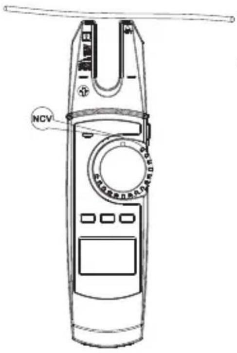
Durch den hochempfindlichen NCV-Sensor, kann die NCV-Signalanzeige (11) auch bei statischen Aufladungen aufleuchten. Dies ist normal und keine Fehlfunktion.
10. Zusatzfunktionen
a) Automatische Abschaltung
- Das Produkt schaltet nach 15 Minuten automatisch ab, wenn keine Taste oder der Drehschalter nicht betätigt wurde. Diese Funktion schützt und schont die Batterien und verlängert die Betriebszeit. Zum Wiedereinschalten, drücken Sie eine Taste des Geräts oder stellen Sie den Drehschalter in die Stellung OFF, schalten die Stromzange wieder ein und wählen dann erneut die gewünschte Messfunktion aus.
b) Beleuchtung
c) HOLD-Funktion
d) Taschenlampenfunktion
Die Taschenlampenfunktion funktioniert nur, wenn das Messgerät eingeschaltet ist.
11. Wartung
• Die Stromzange ist bis auf eine gelegentliche Reinigung und dem Batteriewechsel wartungsfrei.
- Es sind keinerlei für Sie zu wartende Bestandteile im Inneren des Produkts, öffnen Sie es deshalb niemals (bis auf die in dieser Bedienungsanleitung beschriebene Vorgehensweise beim Einlegen/Wechseln der Batterien).
- Eine Wartung oder Reparatur ist nur durch eine Fachkraft oder Fachwerkstatt zulässig.

Überprüfen Sie regelmäßig die technische Sicherheit des Gerätes und der Prüfleiter z.B. auf Beschädigung des Gehäuses oder Quetschung usw.
12. Pflege und Reinigung
Bevor Sie das Gerät reinigen, beachten Sie unbedingt folgende Sicherheitshinweise:

Verwenden Sie auf keinen Fall aggressive Reinigungsmittel, Reinigungsalkohol oder andere chemische Lösungen, da dadurch das Gehäuse und andere Oberflächen des Messgerätes angegriffen oder gar die Funktion beeinträchtigt werden kann.
Beim Öffnen von Abdeckungen oder Entfernen von Teilen, außer wenn dies von Hand möglich ist, können spannungsführende Teile freigelegt werden.
Vor einer Reinigung oder Instandsetzung müssen die angeschlossenen Leitungen vom Messgerät und von allen Messobjekten getrennt werden. Schalten Sie die Stromzange aus.
13. Entsorgung
a) Produkt
Elektronische Geräte sind Wertstoffe und gehören nicht in den Hausmüll. Entsorgen Sie das Produkt am Ende seiner Lebensdauer gemäß den geltenden gesetzlichen Bestimmungen. Entnehmen Sie evtl. eingelegte Batterien und entsorgen Sie diese getrennt vom Produkt.
b) Batterien
Sie als Endverbraucher sind gesetzlich (Batterieverordnung) zur Rückgabe aller gebrauchten Batterien verpflichtet; eine Entsorgung über den Hausmüll ist untersagt.
Schadstoffhaltige Batterien sind mit dem nebenstehenden Symbol gekennzeichnet, das auf das Verbot der Entsorgung über den Hausmüll hinweist. Die Bezeichnungen für das ausschlaggebende Schwermetall sind: Cd=Cadmium, Hg=Quecksilber, Pb=Blei (die Bezeichnung steht auf den Batterien z.B. unter dem links abgebildeten Mülltonnen-Symbol).
Ihre verbrauchten Batterien können Sie unentgeltlich bei den Sammelstellen Ihrer Gemeinde, unseren Filialen oder überall dort abgeben, wo Batterien verkauft werden.
Sie erfüllen damit die gesetzlichen Verpflichtungen und leisten Ihren Beitrag zum Umweltschutz.
14. Technische Daten
a) Stromzange
Stromversorgung 2 x 1,5 V/DC AA Batterie
Messkategorien ....CAT II 1000 V, CAT III 600 V
Abschaltfunktion ....nach ca. 15 Minuten
Öffnungsbereich Stromzange......max. 14,7 mm
LC-Display....max. 6000 Counts (Zeichen)
Batterielebensdauer ....45 -130 Stunden im Normalbetrieb
Batteriestandsanzeige ....bei ≤2,4 V
Eingangsimpedanz......DCV (≥10 MΩ)
| Betriebsbedingungen...... | 0 bis 30 °C; <80 % |
| +30 bis +40 °C, <75 % | |
| +40 bis +50 °C, <45 % | |
| relative Luftfeuchte (nicht kondensierend) |
Lagerbedingungen....-20 bis +60 °C, <80%
Betriebshöhe ......max. 2000 m
Abmessungen (B x H x T) ......ca. 209 x 53 x 35 mm
Gewicht...... ca. 184 g (ohne Zubehör)
ca. 410 g (mit Zubehör)
b) Messtoleranzen
Wechselstrom
| Bereich Auflösung Genauigkeit | |
| 200 A 0,1 A ± (2,5 % + 5) | |
| Überlastschutz: 750 V/AC, 200 A; Frequenzbereich: 50 - 60 Hz | |
Gleichstrom
| Bereich Auflösung Genauigkeit | |
| 200 A 0,1 A ± (2,5 % + 5) | |
| Überlastschutz: 1000 V/DC, 200 ADC-Genauigkeit: Nach erfolgter DC-Nullstellung (ZERO) | |
Wechselspannung
| Bereich Auflösung | Genauigkeit | |
| 6,0 V 0,001 V | ± (1,2 % + 5) | |
| 60,0 V 0,01 V | ||
| 600,0 V 0,1 V | ± (1,2 % + 3) | |
| 750 V | 1 V | ± (1,5 % + 5) |
| Frequenzbereich: 45 - 400 Hz; wenn <400 mV: 50 - 100 Hz, Überlastschutz: 750 V/AC; Impedanz: >10 MΩ | ||
Gleichspannung
| Bereich Auflösung Genauigkeit | |
| 6,0 V 0,001 V ± (0,8 % + 3) | |
| 60,0 V 0,01 V ± (0,8 % + 3) | |
| 600,0 V 0,1 V ± (0,8 % + 3) | |
| 1000,0 V 1 V ± (1 % + 5) | |
| Überlastschutz: 1000 V/DC, 200 A; Impedanz: >10 MΩ | |
Widerstand
| Bereich Auflösung Genauigkeit | |
| 600,0 Ω 0,1 Ω ± (1,2 % + 2) | |
| 6,00 kΩ 0,001 kΩ ± (1,0 % + 2) | |
| 60,00 kΩ 0,01 kΩ ± (1,0 % + 2) | |
| 600,00 kΩ 0,1 kΩ ± (1,0 % + 2) | |
| 6,00 MΩ 0,001 MΩ ± (1,2 % + 2) | |
| 60,00 MΩ 0,01 MΩ ± (1,5 % + 5) | |
| Überlastschutz: 1000 V/DC, 750 V/AC, 200 A | |
Kapazität
| Bereich Auflösung Genauigkeit | ||
| 60,00 nF 0,01 nF ± (4 % + 20) | ||
| 600,00 nF 0,1 nF | ||
| 6,00 μF | 0,001 μF | ± (4 % + 20) |
| 60,00 μF | 0,01 μF | |
| 600,00 μF | 0,1 μF | |
| 6,000 mF 0,001 mF ± 10 % | ||
| 60,00 mF 0,01 mF Nur zur Information! | ||
| Überlastschutz: 1000 V/DC; 750 V/AC | ||
Diodentest
Bereich Auflösung Genauigkeit
6,00 V 0,001 V 0,5 - 0,8 V
Überlastschutz: 1000 V/DC,750 V/AC, 200 A, Prüfspannung ca. 3,3 V
Akustische Durchgangsprüfung
Bereich Auflösung Genauigkeit
600,00 Ω 0,1 Ω <10 Ω Dauerton <10 Ω Dauerton
100 Ω (kein Ton)
Überlastschutz: 1000 V/DC,750 V/AC, 200 A, Prüfspannung ca. 1,2 V
Berührungslose Spannungsmessung
Bereich Abstand
100 - 750 V/AC Bei <10 mm: Dauerton und LED blinkt
Page
a) Symbols in these operating instructions....34
b) Symbols on the product....35
a) General information....38
b) Connected devices....38
c) Batteries....39
d) Persons and product....39
a) Current clamp....41
b) Symbols on LC display....42
a) Inserting the batteries....43
b) Replacing the batteries....44
a) Switching on/off and selecting the measuring function 45
b) Relative measurement 46
c) Current measurement 'A'......46
d) Voltage measurement 'V'......49
e) Resistance measurement....51
f) Continuity testing....52
g) Diode testing 53
h) Capacitance measurement ....53
i) Non-contact AC voltage detection (NCV)....54
a) Automatic shut-off ....55
b) Backlight....56
c) 'HOLD' function 56
d) Torch function....56
a) Product....58
b) Batteries....58
a) Current clamp....58
b) Measurement tolerances....59
1. Introduction
Dear customer
Thank you for purchasing this product.
This product complies with statutory, national and European regulations.
To ensure that the product remains in this state and to guarantee safe operation, always follow the information in these operating instructions.

These operating instructions are part of this product. They contain important information on setting up and using the product. Do not give this product to a third party without the operating instructions. Therefore, retain these operating instructions for reference!
If there are any technical questions, please contact:
www.conrad.com/contact
2. Description of symbols
a) Symbols in these operating instructions
The symbol with the lightning in a triangle indicates that there is a risk to your health, e.g. due to an electric shock.

The symbol with an exclamation mark in a triangle points to important information in these operating instructions which must be observed.
The arrow symbol indicates special information and tips on how to use the product.
b) Symbols on the product
Symbol Meaning

This symbol indicates that this product is built according to protection class II. It is equipped with reinforced or dual insulation between the mains circuit and the output voltage.

Earth potential

The symbol with the exclamation mark in the triangle is used if there is a risk to your health, e.g. due to an electric shock.

AC voltage

DC voltage

Acoustic signals on/off

Diode

Capacitance measurement range

A lightning symbol in a square permits current measurements on uninsulated, hazardous/active conductors and warns of the possible hazards. Personal protective equipment must be used.

This product has been CE-tested and meets the relevant European guidelines.
CAT II
Measurement category II: for measuring electrical and electronic devices that are directly supplied with a mains voltage via a mains plug. This category also includes all lower categories (e.g. CAT I for measuring signal and control voltages).
CAT III
Overvoltage category III for measuring in building installation (e.g. outlets or sub-distribution). This category also includes all lower categories (e.g. CAT II for measuring electrical devices). Measuring operation in CAT III is only permitted with probe tips with a maximum free contact length of 4 mm or with cover caps above the measuring probes.

Polarity marking (positive pole) for direct current measurement. The symbols show the direction of the current flow to ensure the correct polarity when measuring.

Position marker for the conductor to ensure the correct current measurement.
3. Intended use
The product is intended for measuring and displaying electrical parameters in the range of the overvoltage categories CAT II to max. 1000 V and CAT III to max. 600 V against earth potential, in accordance with EN 61010-1, EN 61010-2-032, EN 61010-2-033 and all lower categories.
Measurements must not be carried out under unfavourable ambient conditions. Adverse conditions include:
Only use test leads that conform to the specifications of the measuring device.
Only use batteries of the specified type.
The measuring device must not be used when it is open, when the battery compartment is open or when the battery compartment cover is missing.
This product is intended for indoor use only. Do not use it outdoors. Contact with moisture (e.g. in a bathroom) must be avoided under all circumstances.
For safety and approval purposes, do not rebuild and/or modify this product. Using the product for purposes other than those described above may damage the product. In addition, improper use can cause hazards such as a short circuit, fire or electric shock. Read the operating instructions carefully and store them in a safe place. Only make this product available to third parties together with its operating instructions.
All company and product names are trademarks of their respective owners. All rights reserved.
4. Package contents
- Operating instructions
Up-to-date operating instructions
Download the up-to-date operating instructions at www.conrad.com/downloads or scan the QR code shown. Follow the instructions on the website.
5. Features and functions
• CAT II 1000 V, CAT III 600 V measurements
• True RMS (effective value function)
• Automatic selection of measurement range
- Backlight
• Current range max. 200 A
• Non-contact AC voltage testing (NCV)
- Display of measurement range exceeded 'OL'
• Function for holding the measurement display
- Zero adjustment
6. Safety information
Read the operating instructions carefully and the safety information in particular. If you do not follow the safety information and information on proper handling in these operating instructions, we will assume no liability for any resulting personal injury or damage to property. Such cases will invalidate the warranty/guarantee.
a) General information
b) Connected devices
- Always observe the safety information and operating instructions of any other devices which are connected to the product.
c) Batteries
d) Persons and product
7. Controls and symbols
a) Current clamp
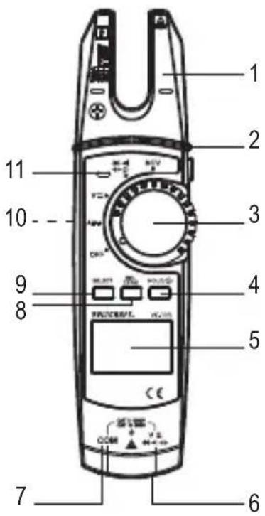
1 Current clamp
2 Torch button
3 Rotary switch for selecting the measuring mode
4 HOLD/ button
5 LC display
6 V measuring socket (
7 COM measuring socket
8 REL ZERO button
9 SELECT button
10 Battery compartment (back)
11 NCV signal display


b) Symbols on LC display
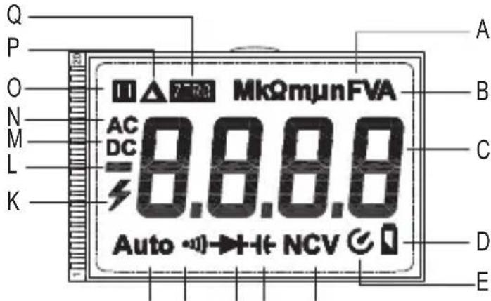
FGHIJ
No. Symbol Meaning
| A Ω | Ohm (unit of electrical resistance) | |
| kΩ, MΩ | Kiloohm (exp. 3), megaohm (exp. 6) | |
| Hz | Hertz (unit of electrical frequency) | |
| mV | Millivolt (exp. -3) | |
| mA, μA | Milliampere (exp. -3), micro-ampere (exp. -6) | |
| nF | Nanofarad (exp. -9; unit of electrical capacitance) | |
| μF | Microfarad (exp. -6) | |
| mF | Millifarad (exp. -3) |
B V A Volt (unit of electrical voltage)
Ampere (unit of electrical current)
C - Measured value display
D Battery capacity
E Automatic shut-off
F NCV Non-contact AC recognition
G Symbol for capacitance
H Diode test symbol
I ·s Acoustic continuity tester symbol
J Auto Automatic measurement range is enabled
No. Symbol Meaning
K Lightning icon for voltage measuring
L + - Displays the sign of the measured value
M DC Direct voltage/current
N AC Alternating voltage/current
O HOLD function is active when the symbol is displayed
P Relative measurement is set
Q Zero res ZERO
8. Inserting/changing the batteries
a) Inserting the batteries
Batteries are not normally inserted when the product is delivered to you. Using rechargeable batteries is not recommended due to their low voltage.
Follow the steps below to prepare the product for use.
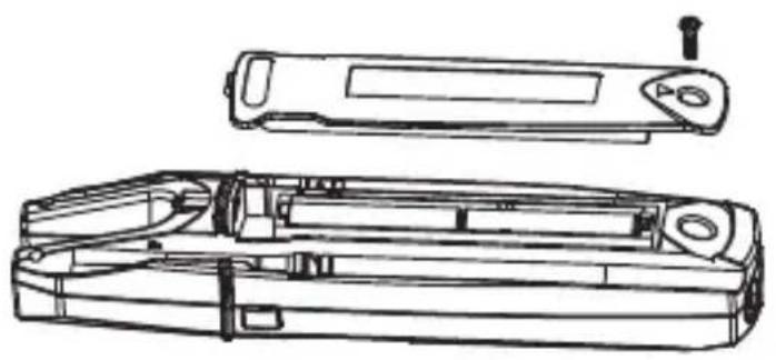
natural_image
Technical line drawing of a device casing with internal components and a top view (no text or symbols)Fig. 1
b) Replacing the batteries
The batteries need to be replaced if the symbol ☐(D) lights up on the LC display (5) or the backlight is dim or does not come on at all. Replace the batteries as soon as possible as described in 'a) Inserting the batteries'. If only the ☐symbol is displayed after switching the device on, replace the batteries immediately.
9. Measuring mode
Never exceed the maximum permitted input values. Never touch circuits or parts of circuits when they may contain voltages greater than 33 V/AC RMS or 42 V/DC. Danger of death!

The maximum permitted voltage in the measuring circuit against earth potential must not exceed 1000 V in CAT II and 600 V in CAT III.
Before taking measurements, check the connected test leads for damage such as cuts, cracks or pinches. Defective test leads must be taken out of use. Danger of death!
When taking measurements, do not touch any area beyond the grip markings on the probe tips.
Only the two test leads required for measuring operation may be connected to the measuring device at any one time. For safety reasons, remove all unnecessary test leads from the measuring device when carrying out a current measurement.
Measurements in circuits rated at >33 V/AC and >42 V/DC may only be carried out by qualified and trained personnel who are familiar with the regulations and the associated hazards.
Pay attention to the requisite safety information, regulations and protective measures for your own safety.
The measured values are displayed on the current clamp's LC display (5). Negative polarity readings are indicated with the (-) sign automatically.
→ < OL > (overload) on the LC display (5) indicates that the measurement range has been exceeded.
The plugs on the test leads are fitted with protective transport caps. Remove them before pushing the plugs into the connection sockets on the measuring device.
a) Switching on/off and selecting the measuring function
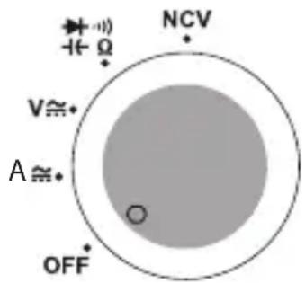
Fig. 2
- Some measuring functions must be set with the help of the SELECT button (9). Refer to the relevant sections.
→ Important! Ensure that you have selected the correct measuring function before each measurement.
- When a button or rotary switch is actuated, a beep sounds if a switching process was valid. If an operation is invalid, the buzzer sounds twice.
b) Relative measurement
You can measure values absolutely (normal measuring mode) or measure a value in relation to the previous measurement.
c) Current measurement 'A'
The current is measured wirelessly via the current clamp (1). The sensors in the current clamp detect the magnetic field created by current-carrying conductors.
→ Ensure that the conductor always passes through the current clamp correctly (observe the line markings).
Do not use the current clamp to surround more than one conductor.
AC current measurement A ≈
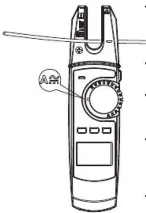
AC current measurement A with zero adjustment
Due to the high sensitivity and the ambient magnetic field (e.g. the earth's magnetic field), a small current will always be displayed when the current clamp is closed and in the direct current measurement range. Manually reset the display to zero immediately before each measurement or when the cable is changed. To perform zero adjustment, proceed as follows:
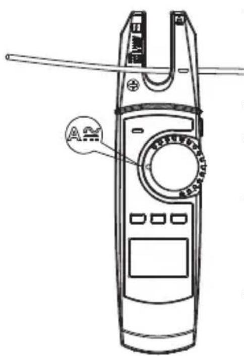
• After a successful zero adjustment, route the individual conductor that is to be measured into the current clamp. Position the conductor along the two direction lines at the bottom end of the U-shaped current clamp.
• The measured current is shown on the LC display.
- A positive or negative symbol is also displayed with the display value, depending on the direction of insertion.
A minus '-' symbol before the measured value indicates that the current is flowing in the opposite direction (or the current clamp terminals have been reversed).
d) Voltage measurement 'V'
AC voltage measurement (V)
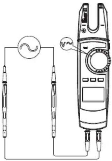
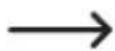
If the voltage exceeds 30 V/AC, the LC display shows a visual high-voltage warning to warn of the danger of an electric shock.
• After completing the measurement, remove the current clamp from the measured object and switch the product off.
DC voltage measurement (V)
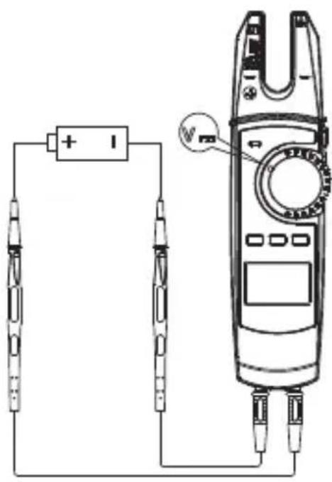
If the voltage exceeds 42 V/DC, the LC display shows a visual high-voltage warning to warn of the danger of an electric shock.
- The current measured value is displayed together with the respective polarity.
If a minus '-' appears in front of the measured value for direct voltage, the measured voltage is negative (or the test leads have been swapped).
e) Resistance measurement

Ensure that all objects that you wish to measure (including circuit components, circuits and component parts as well as other measured objects such as capacitors) are disconnected and discharged.
natural_image
Pure electrical circuit lines without any symbols
Before measuring in the measurement range of 600 Ω, hold the probe tips together to short circuit them. Press the REL ZERO button (8) to reset the displayed value. This compensates for the influence of resistance in the probe tips.
When taking a resistance measurement, ensure that the points that come into contact with the probe tips are free from dirt, oil, solder and other impurities. These substances may distort the measurement.
f) Continuity testing

Ensure that all objects that you wish to measure (including circuit components, circuits and component parts as well as other measured objects, e.g. capacitors) are disconnected and discharged.
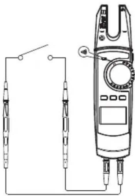
natural_image
Pure electrical circuit lines without any symbols- Switch the product on at the rotary switch (3) and select the measurement range
- Press the SELECT button (9) to select the measurement range for continuity testing ... appears on the LC display.
- Insert the red test lead into the V socket (6) and the black test lead into the COM socket (7).
- Connect both of the probe tips to the measured object (component, circuit, etc.). Connect the red probe tip to the positive terminal and the black probe tip to the negative terminal.
- If the measured resistance value is less than 10 ohms, an acoustic signal sounds continuously, if it is between 10 and 100 ohms, a beep may or may not be emitted. No acoustic signal is emitted above 1000 ohms.
• After completing the measurement, remove the current clamp from the measured object and switch the product off.
g) Diode testing

Ensure that all objects that you wish to measure (including circuit components, circuits and component parts as well as other measured objects, e.g. capacitors) are disconnected and discharged.
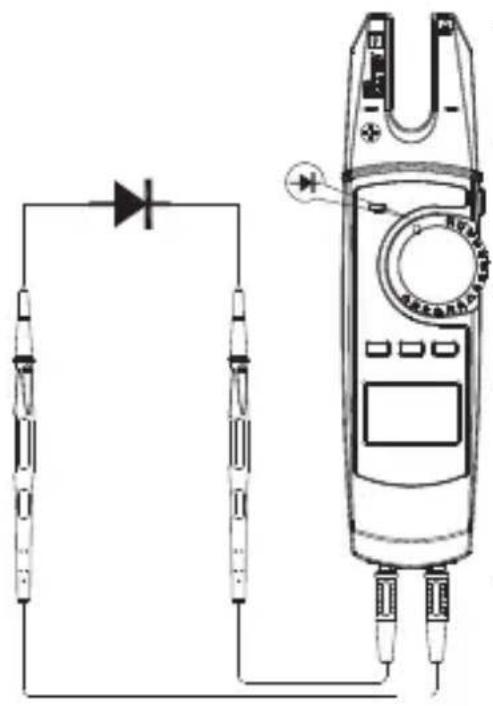
natural_image
Pure electrical circuit lines without any symbols
To obtain the most accurate results, it is recommended that components are removed from the circuits.
h) Capacitance measurement

Ensure that all objects that you want to measure (including circuit components, circuits and component parts as well as other measured objects) are disconnected and discharged.
Always pay attention to the polarity when using electrolytic capacitors.
It is recommended that you perform a zero adjustment for capacitance measurements in the 60 nF range to compensate for the resistance in the test leads. To do so, briefly press the REL ZERO button (8).
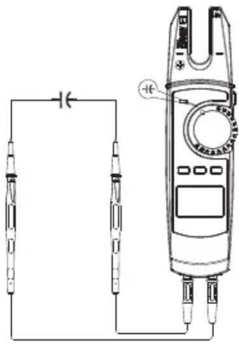
natural_image
Pure electrical circuit lines without any symbols- Switch the product on at the rotary switch (3) and select the measurement range +-
- Press the SELECT button (9) to select the measurement range for the capacitance measurement +1. - appears on the LC display.
- Insert the red test lead into the V socket (6) and the black test lead into the COM socket (7).
- Now connect the two probe tips to the capacitor to be measured. Connect the red probe tip to the positive terminal and the black probe tip to the negative terminal. Please observe the correct polarity. The capacitance is shown on the display after a few seconds. Wait until the display stabilises.
- If < OL > (overload) appears on the LC display, you have exceeded the measurement range or the measuring circuit has been interrupted.
• After completing the measurement, remove the current clamp from the measured object and switch the product off.
Due to the sensitive measuring input, the LC display may show a small reading even with 'open' test leads.
i) Non-contact AC voltage detection (NCV)

The voltage detector is only designed for quick tests and by no means replaces a contact voltage test. This method is not to be used for checking that no voltage is present before carrying out work.
The NCV function (non-contact voltage detection) enables the contactless detection of an AC voltage on conductors. The NCV sensor is attached to the tip on the current clamp.
→ Always test the NCV function first on a known AC voltage source to avoid incorrect measurements. Incorrect measurements may cause an electric shock.
Proceed as follows:
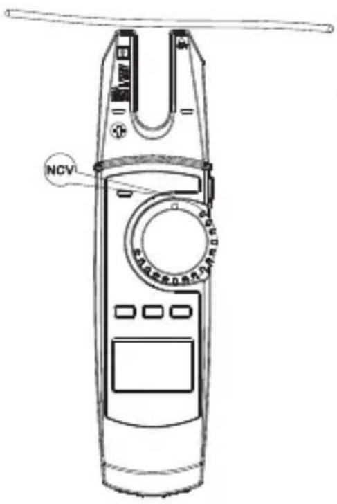
Due to the highly sensitive NCV sensor, the NCV signal display (11) may also light up for static charges. This is normal and does not indicate that the product is faulty.
10. Additional functions
a) Automatic shut-off
- The device shuts off automatically after 15 minutes if no button is pressed or the rotary switch is not turned. This function protects the batteries and extends the operating time. To switch the device back on, press a button on the device or set the rotary switch to the OFF position, switch the current clamp back on and then select the desired measuring function again.
b) Backlight
c) 'HOLD' function
d) Torch function
The torch function only works when the measuring device is switched on.
11. Maintenance

Regularly check the technical safety of the device and test leads, e.g. check for damage to the housing or crushing, etc.
12. Care and cleaning
Be sure to pay attention to the following safety information before cleaning the device:

Never use aggressive detergents, rubbing alcohol or other chemical solutions, as these may damage the housing and other surfaces on the device or stop it from functioning properly.
Live components may be exposed if covers are opened or parts are removed, unless this can be done by hand.
Before cleaning or servicing the, disconnect all cables from the measuring device and all measured objects. Switch the current clamp off.
13. Disposal
a) Product
Electronic devices are recyclable waste and must not be placed in household waste. At the end of its service life, dispose of the product according to the relevant statutory regulations. Remove any inserted batteries and dispose of them separately from the product.
b) Batteries
As the end user, you are required by law (Battery Ordinance) to return all used batteries; they must not be disposed of in household waste!
Contaminated batteries are labelled with this symbol to indicate that disposal in the domestic waste is forbidden. The abbreviations for heavy metals in batteries are: Cd = Cadmium, Hg = Mercury, Pb = Lead (indicated on the battery, e.g. below the waste bin icon on the left).
Used batteries can be returned free of charge to local collection points, our stores or battery retailers.
You thus fulfil your statutory obligations and contribute to environmental protection.
14. Technical data
a) Current clamp
Power supply 2 x 1.5 V/DC AA batteries
Measurement categories....CAT II 1000 V, CAT III 600 V
Shut-off function ......after approx. 15 minutes
Opening range of current clamp ..... max. 14.7 mm
LC display....max. 6000 counts (characters)
Battery life....45 - 130 hours in normal operation
Battery status display ....at ≤2.4 V
Input impedance ....DCV (≥10 MΩ)
Operating conditions.... 0 to 30 °C; <80 %
+30 to +40 °C, <75 %
+40 to +50 °C, <45 %
relative humidity (non-condensing)
Storage conditions....-20 to +60 °C, <80 %
Operating altitude ......max. 2000 m
Dimensions (W x H x D) ....approx. 209 x 53 x 35 mm
Weight .... approx. 184 g (without accessories)
approx. 410 g (with accessories)
b) Measurement tolerances
Alternating current
| Range Resolution Accuracy | |
| 200 A 0.1 A ± (2.5% + 5) | |
| Overload protection: 750 V/AC, 200 A; Frequency range: 50 - 60 Hz | |
Direct current
| Range Resolution Accuracy | ||
| 200 A 0.1 A ± (2.5% + 5) | ||
| Overload protection: 1000 V/DC, 200 ADC accuracy After DC zero reset (ZERO) | ||
AC voltage
| Range Resolution Accuracy | ||
| 6.0 V 0.001 V ± (1.2 % + 5) | ||
| 60.0 V 0.01 V | ||
| 600.0 V 0.1 V | ± (1.2 % + 3) | |
| 750 V | 1 V | ± (1.5 % + 5) |
| Frequency range: 45 - 400 Hz; If <400 mV: 50 - 100 Hz; Overload protection: 750 V/AC; Impedance: >10 MΩ | ||
DC voltage
| Range Resolution Accuracy | ||
| 6.0 V 0.001 V ± (0.8 % + 3) | ||
| 60.0 V 0.01 V ± (0.8 % + 3) | ||
| 600.0 V 0.1 V ± (0.8 % + 3) | ||
| 1000.0 V 1 V ± (1 % + 5) | ||
| Overload protection: 1000 V/DC, 200 A; Impedance: >10 MΩ | ||
Resistance
| Range Resolution Accuracy | |
| 600.0 Ω 0.1 Ω ± (1.2 % + 2) | |
| 6.00 k 0.001 k ± (1.0 % + 2) | |
| 60.00 k 0.01 k ± (1.0 % + 2) | |
| 600.00 k 0.1 k ± (1.0 % + 2) | |
| 6.00 MΩ 0.001 MΩ ± (1.2 % + 2) | |
| 60.00 MΩ 0.01 MΩ ± (1.5 % + 5) | |
| Overload protection: 1000 V/DC, 750 V/AC, 200 A | |
Capacitance
| Range Resolution Accuracy | ||
| 60.00 nF 0.01 nF | ± (4 % + 20) | |
| 600.00 nF 0.1 nF | ± (4 % + 20) | |
| 6.00 μF | 0.001 μF | |
| 60.00 μF | 0.01 μF | |
| 600.00 μF | 0.1 μF | |
| 6.000 mF | 0.001 mF | ±10% |
| 60.00 mF | 0.01 mF | For information only! |
| Overload protection: 1000 V/DC; 750 V/AC | ||
Diode testing
| Range Resolution Accuracy | ||
| 6.00 V 0.001 V 0.5 - 0.8 V | ||
| Overload protection: 1000 V/DC,750 V/AC, 200 A, test voltage approx. 3.3 V | ||
Acoustic continuity test
| Range Resolution Accuracy | ||
| 600.00 Ω 0.1 Ω < 10 Ω continuous tone | <10 Ω continuous tone>100 Ω (no tone) | |
| Overload protection: 1000 V/DC,750 V/AC, 200 A, test voltage approx. 1.2 V | ||
Non-contact voltage measurement
| Range Distance | |
| >100 - 750 V/AC At <10 mm: Continuous tone and LED flashes | |
Page
a) Symboles dans ce mode d'emploi....64
b) Symboles sur le produit....65
a) Généralités....68
b) Appareils connectés....69
c) Piles....69
d) Personnes et produit....69
a) Pince ampèremétrique....71
b) Symboles à l'écran à cristaux liquides ....72
a) Insertion des piles ....73
b) Remplacement des piles....74
a) Sélectionner marche/arrêt/fonction de mesure ....75
b) Mesure relative....76
c) Mesure du courant « A »....76
d) Mesure de la tension « V »......79
e) Mesure de la résistance....81
f) Contrôle de continuité ....82
g) Test de diodes....83
h) Mesure de la capacité....83
i) Détection de tension alternative sans contact (NCV)....84
a) Mise hors tension automatique ....85
b) Éclairage 86
c) Fonction HOLD....86
d) Fonction lampe de poche....86
a) Produit....88
b) Piles....88
a) Pince ampèremétrique....88
b) Tolérances de mesure....89
1. Introduction
Chers clients,
Nous vous remercions d'avoir choisi ce produit.
Ce produit est conforme aux exigences des normes européennes et nationales en vigueur.
Afin de maintenir l'appareil en bon état et d'en assurer un fonctionnement sans danger, l'utilisateur doit impérativement respecter ce mode d'emploi !

Ce mode d'emploi fait partie intégrante du produit. Il contient des consignes importantes pour la mise en service et la manipulation du produit. Tenez compte de ces remarques, même en cas de cession de ce produit à un tiers. Conservez ce mode d'emploi afin de pouvoir le consulter à tout moment !
Pour toute question technique, veuillez vous adresser à:
France (email): technique@conrad-france.fr
Suisse: www.conrad.ch
2. Explication des symboles
a) Symboles dans ce mode d'emploi
Le symbole de l'éclair dans un triangle indique un risque pour votre santé, par ex. suite à un choc électrique.

Le symbole avec le point d'exclamation placé dans un triangle signale les informations importantes du présent mode d'emploi qui doivent impérativement être respectées.
Le symbole de la flèche précède les conseils et remarques spécifiques à l'utilisation.
b) Symboles sur le produit
Symbole Signification

Ce symbole indique que cet appareil est conforme à la classe de protection II. Il possède une isolation double ou renforcée entre le réseau d'alimentation et la tension de sortie.

Potentiel de terre

Le symbole avec le point d'exclamation placé dans un triangle est employé lorsqu'il y a un danger pour votre santé, par exemple en cas d'électrocution.

Tension alternative

Tension continue

Signaux acoustiques marche/arrêt

Diode

Symbole pour la plage de mesure de capacité

Le symbole d'éclair dans un carré indique qu'il est possible d'effectuer des mesures sur des conducteurs non isolés (conducteurs actifs dangereux) et met en garde contre les risques possibles. L'utilisation d'un équipement de protection individuelle est requise.

Cet appareil est homologué CE et satisfait aux directives européennes requises
CAT II
Catégorie de mesure II pour des relevés de mesure sur les appareils électriques et électroniques, qui sont alimentés via une fiche de secteur directement reliée à la tension de réseau. Cette catégorie comprend aussi toutes les catégories inférieures (p. ex CAT I pour la mesure des tensions des signaux et des commandes).
CAT III
Catégorie de mesure III pour des relevés de mesure dans les installations d'un bâtiment (p. ex. prises de courant ou distributions secondaires). Cette catégorie comprend également toutes les catégories inférieures (telles que la CAT II pour les mesures réalisées sur les appareils électriques). Le mode de mesure en CAT III est autorisé uniquement avec des pointes de mesure ayant une longueur de contact libre de 4 mm max., ou avec des caches de protection sur les pointes.

Repère de polarité (pôle positif) pour la mesure du courant continu. Le symbole indique le sens de circulation du courant afin de pouvoir mesurer la polarité correcte.
- Marquage de position pour le conducteur pour une mesure du courant correcte.
3. Utilisation prévue
Ce produit sert à mesurer et afficher les valeurs électriques appartenant aux catégories de surtension CAT II jusqu'à 1000 V max. et CAT III jusqu'à 600 V max., par rapport au potentiel terrestre conformément aux normes EN 61010-1, EN 61010-2-032, EN 61010-2-033, ou à toutes les catégories inférieures.
Les mesures ne doivent pas être effectuées dans des conditions ambiantes défavorables. Les conditions ambiantes défavorables renvoient par exemple :
Pour les prises de mesure, n'utilisez que des conducteurs de test qui répondent aux caractéristiques du multimètre.
L'appareil est conçu pour fonctionner uniquement avec le type de pile indiqué.
L'instrument de mesure ne doit pas être utilisé lorsqu'il est ouvert, que le compartiment des piles est ouvert ou que le couvercle du compartiment des piles manque.
L'utilisation est uniquement autorisée en intérieur, dans des locaux fermés ; l'utilisation en plein air est interdite. Évitez impérativement tout contact avec l'humidité, par ex. dans la salle de bain, etc.
Pour des raisons de sécurité et d'homologation, toute transformation et/ou modification du produit est interdite. Si vous utilisez le produit à des fins autres que celles décrites précédemment, vous risquez de l'endommager. Par ailleurs, une utilisation incorrecte peut être source de dangers tels que les courts-circuits, les incendies, l'électrocution. Lisez attentivement le mode d'emploi et conservez-le. Ne donnez le produit à un tiers qu'accompagné de son mode d'emploi.
Tous les noms d'entreprises et appellations de produits contenus dans ce mode d'emploi sont des marques déposées de leurs propriétaires respectifs. Tous droits réservés.
4. Contenu d'emballage
- Mode d'emploi
Modes d'emploi actuels
Téléchargez les modes d'emploi actualisés via le lien www.conrad.com/downloads ou scannez le Code QR illustré. Suivez les instructions disponibles sur le site Internet.
5. Caractéristiques et fonctions
• Mesures CAT II 1000V, CAT III 600V
• True RMS (Fonction des valeurs efficaces)
- Sélection automatique de la plage de mesure
- Rétroéclairage
- Plage de courant max. 200 A
- Détecteur de tension sans contact (fonction NCV)
- Affichage du dépassement de la plage de mesure « OL »
- Fonction pour geler la mesure dans l'affichage
- Remise à zéro
6. Consignes de sécurité
Lisez attentivement le mode d'emploi dans son intégralité, en étant particulièrement attentif aux consignes de sécurité. Nous déclinons toute responsabilité en cas de dommage corporel ou matériel résultant du non-respect des consignes de sécurité et des instructions d'utilisation de ce mode d'emploi. En outre, la garantie est annulée dans de tels cas.
a) Généralités
b) Appareils connectés
- Respectez également les consignes de sécurité et le mode d'emploi des autres appareils connectés au produit.
c) Piles
d) Personnes et produit
7. Commandes et symboles
a) Pince ampèremétrique
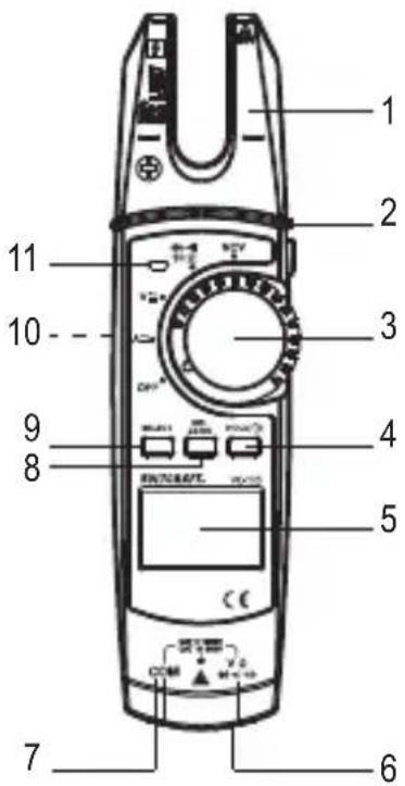
1 Pince ampèremétrique
2 Bouton de lampe de poche
3 Commutateur rotatif pour sélectionner les fonctions de mesure
4 Touche HOLD/
5 Écran LCD
6 Prise de mesure V( ∀←Ω)
7 Prise de mesure COM
8 Touche REL ZERO
9 Touche SELECT
10 Compartiment à piles (à l'arrière)
11 Affichage du signal NCV
b) Symboles à l'écran à cristaux liquides
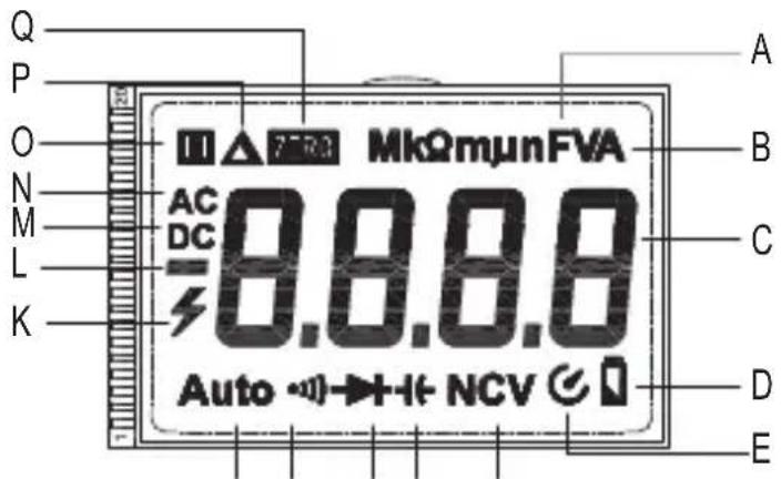
FGHIJ
N° Symbole Explication
| A Ω | Ohm (unité de résistance électrique) | |
| kΩ, MΩ | Kilo-ohm (exp.3), mégahom (exp.6) | |
| Hz | Hertz (unité de fréquence électrique) | |
| mV | Millivolt (exp.-3) | |
| mA, μA | Milliampère (exp.-3), microampère (exp.-6) | |
| nF | Nano Farad (exp.-9 ; unité de capacité électrique) | |
| μF | Micro Farad (exp.-6) | |
| mF | Milli Farad (exp.-3) |
B V A Volt (unité de tension électrique)
Ampère (unité d'intensité de courant électrique),
C - Affichage de la valeur mesurée
D Capacité des piles
E Mise hors tension automatique
F NCV Détection de la tension alternée sans contact
G Symbole pour la capacité.
H Symbole- test de diodes
I ·s) Symbole du testeur de continuité acoustique
J Auto La sélection automatique de plage de mesure est activée
N° Symbole Explication
K Symbole déclair pour la mesure de la tension
L + - Affichage du signe de la valeur mesurée
M DC Tension continue/courant continu
N CA Tension alternée/courant alternatif
O La fonction HOLD est active lorsque le symbole est affiché
P La mesure relative est réglée
Q Mise à ZERO
8. Insertion/remplacement des piles
a) Insertion des piles
À la livraison du produit, normalement aucune pile n'est installée. L'utilisation d'accumulateurs n'est pas recommandée à cause de leur tension plus faible.
Suivez les étapes décrites ci-dessous, pour mettre le produit en service.
Fig. 1
b) Remplacement des piles
Un remplacement des piles est nécessaire si le symbole (D) s'allume sur l'écran LCD (5) ou si le rétroéclairage est encore faible ou s'il n'est plus allumé. Changez les piles dans les plus brefs délais, voir section « a) Installation des piles ». Si juste après la mise sous tension le symbole s'allume, veuillez remplacer immédiatement les piles.
9. Mode de mesure
Ne dépassez en aucun cas les grandeurs d'entrée maximales autorisées. Ne touchez aucun circuit ou aucune partie des circuits en présence de tensions supérieures à 33 V/CA rms ou à 42 V/CC. Danger de mort !
La tension maximale admissible dans le circuit de mesure électrique contre le potentiel terrestre ne doit pas dépasser 1000 V en CAT II et 600 V en CAT III.
Avant le début de la mesure, assurez-vous de l'absence d'endommagements tels que des coupures, fissures ou pincements au niveau des conducteurs de test raccordés. Ne pas utiliser des conducteurs de test défectueux ! Danger de mort !
Ne saisissez pas les marquages tactiles de la zone de préhension des pointes de la sonde pendant la mesure.
Vous devez raccorder seulement deux conducteurs de test à l'instrument de mesure qui sont nécessaires pour le mode de mesure. Pour des raisons de sécurité, débranchez tous les conducteurs de test inutiles de l'instrument de mesure lorsque vous effectuez une mesure du courant.
Les relevés de mesure sur les circuits électriques >33 V/CA et >42 V/CC doivent impérativement être effectués par des professionnels ou des personnes initiées, qui connaissent les consignes de sécurité et qui sont informés des dangers qui en résultent.
Respectez les consignes de sécurité, les règlements et les mesures de protection applicables afin de garantir votre sécurité.
Les valeurs mesurées s'affichent à l'écran LC (5) de la pince ampèremétrique. Si la valeur de mesure est négative, le signe moins (-) s'affiche automatiquement.
→ Vous avez dépassé la plage de mesure dès que < OL > (pour Overload = dépassement) apparaît sur l'écran à cristaux liquides (5).
Dans les connecteurs des conducteurs de test fournis se trouvent des capuchons de protection pour le transport. Enlevez-les avant d'insérer les connecteurs dans les prises de de raccordement de l'appareil de mesure.
a) Sélectionner marche/arrêt/fonction de mesure
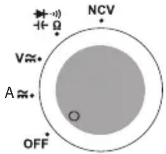
Fig. 2
b) Mesure relative
Vous pouvez mesurer des valeurs de mesure absolues (mode de mesure normal) ou une valeur par rapport à la valeur précédente.
c) Mesure du courant « A »
La mesure du courant s'effectue sans contact via la pince ampèremétrique (1). Les capteurs de la pince ampèremétrique détectent le champ magnétique qui entoure les conducteurs traversés par le courant.
Assurez-vous que le conducteur passe toujours bien au centre de la pince ampèremétrique (prière de respecter l'indicateur d'aide sous la forme d'un trait).
Ne mettez jamais la pince sur plus d'un conducteur à la fois.
Mesure du courant alternatif A ≈
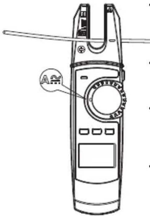
Mesure du courant continu A avec mise à zéro
À cause de la grande sensibilité et du champ magnétique ambiant (p. ex. champ magnétique terrestre, etc.), une valeur de courant plus basse sera toujours indiquée avec une pince ampèremétrique fermée dans une plage de mesure de courant continu. Avant chaque mesure ou si le câble d'alimentation a été changé, l'affichage doit être immédiatement remis manuellement sur zéro. Pour effectuer la remise à zéro, procédez comme suit :
- Chaque pression brève sur la touche REL ZERO déclenche une nouvelle remise à zéro. Pour désactiver cette fonction, appuyez et maintenez la touche REL ZERO pendant env. 2 secondes. Le symbole « ZERO » disparaît. Vous vous trouvez à nouveau dans le mode de mesure normal sans égalisation à zéro.
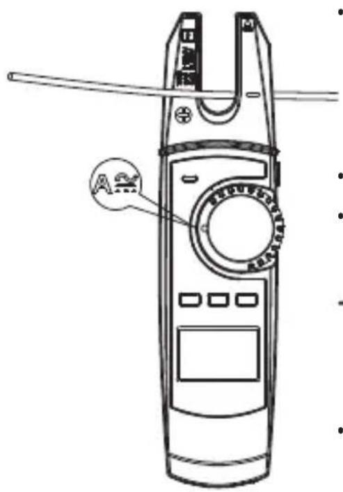
Dès qu'un négatif « - » précède la valeur mesurée d'une mesure de courant continu, le courant passe dans le sens inverse (ou la pince ampèremétrique est inversée).
d) Mesure de la tension « V »
Mesure de tensions alternatives « CA » (V ↗)
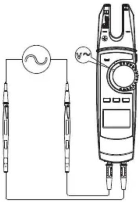
En cas de dépassement d'une tension de 30 V/CA, l'écran LCD affiche un avertissement visuel de haute tension pour vous avertir du risque de choc électrique.
- Une fois la mesure terminée, enlevez la pince et éteignez-la.
Mesure de tensions continues « CC » (V. 7).
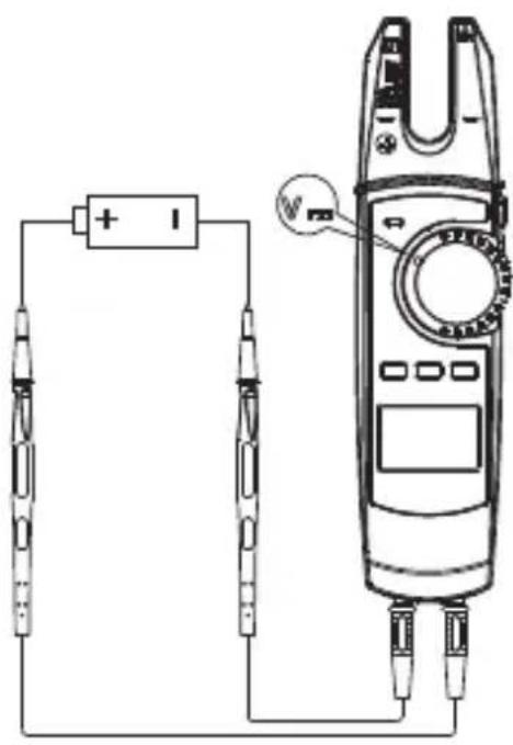
En cas de dépassement d'une tension de 42 V/CC, l'écran LCD affiche un avertissement visuel de haute tension pour vous avertir du risque de choc électrique.
- La valeur de mesure actuelle s'affiche à l'écran, accompagnée du signe de polarité correspondant.
En mode de mesure de tension continue, un signe moins « - » devant la valeur signifie que la tension mesurée est négative (ou que les conducteurs de test sont inversés).
- Ne mesurez pas de tension supérieure à 1000 V/CC. Lors du dépassement de la gamme de mesure (750 V/ CC), des bips sonores retentissent durablement.
- Une fois la mesure terminée, enlevez la pince et éteignez-la.
e) Mesure de la résistance

Assurez-vous que tous les éléments du circuit, tous les circuits, tous les composants, tels que les condensateurs ainsi que les autres objets à mesurer soient impérativement hors tension et déchargés.
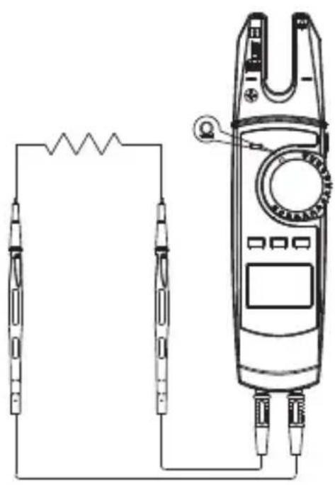
natural_image
Pure electrical circuit lines without any symbols
Avant de mesurer, maintenez les pointes de mesure dans la gamme de mesure de 600 Ω pour les fermer brièvement. Pour ce faire, appuyez sur la touche REL ZERO (8) pour réinitialiser la valeur affichée. Cela compense l'influence de la résistance des pointes de mesure.
Lorsque vous effectuez une mesure de résistance, veillez à ce que les points de mesure que vous touchez avec les pointes de mesure soient exempts de saleté, d'huile, de vernis soudable ou analogues. Ce genre de facteurs peut en effet fausser le résultat de la mesure.
f) Contrôle de continuité

Assurez-vous que tous les éléments du circuit, tous les circuits, tous les composants ainsi que les autres objets à mesurer, tels que les condensateurs soient impérativement hors tension et déchargés.
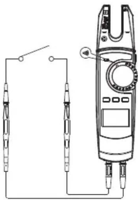
natural_image
Pure electrical circuit lines without any symbols- Allumez l'appareil avec le bouton rotatif (3), et sélectionnez la gamme de mesure
- Appuyez sur la touche SELECT (9) pour sélectionner la gamme de mesure pour le contrôle de continuité »» apparaît sur l'écran à CL.
- Enfichez le conducteur de mesure rouge dans la prise de mesure V (6) et le conducteur de mesure noir dans la prise de mesure COM (7).
- Reliez à présent les deux pointes de la sonde à l'objet à mesurer (composant, circuit, etc.). La pointe de mesure rouge correspond au pôle positif, la pointe de mesure noire au pôle négatif.
- Si la valeur de résistance mesurée est inférieure à 10 ohms, un message sonore retentit de manière continue, si elle est entre 10 et 100 ohms, un son peut éventuellement retentir ou pas. Au-delà de 1000 ohms, aucun message sonore n'est émis.
- Une fois la mesure terminée, enlevez la pince et éteignez-la.
g) Test de diodes

Assurez-vous que tous les éléments du circuit, tous les circuits, tous les composants ainsi que les autres objets à mesurer, tels que les condensateurs soient impérativement hors tension et déchargés.
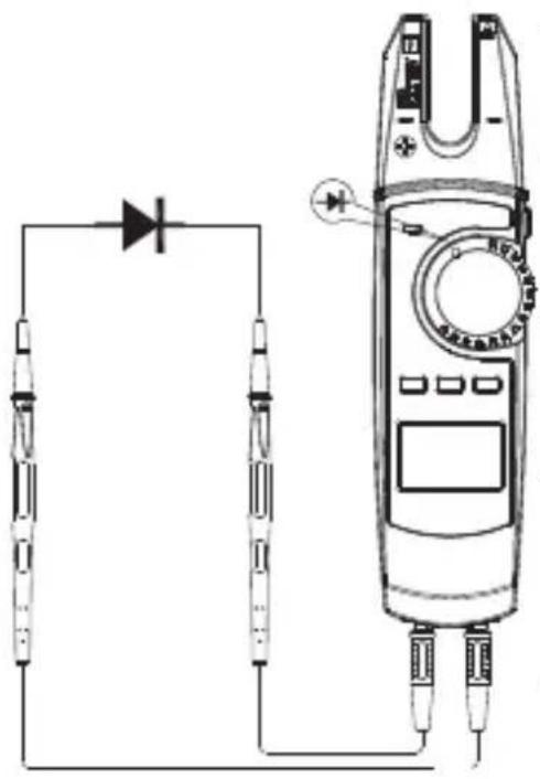
natural_image
Pure electrical circuit lines without any symbols
Pour obtenir les résultats de mesure les plus précis, il est recommandé de retirer les composants des circuits.
h) Mesure de la capacité

Assurez-vous que tous les éléments de circuit, tous les circuits et composants à mesurer, ainsi que d'autres objets de mesure sont bien hors tension.
Respectez impérativement la polarité des condensateurs électrolytiques.
Il est recommandé d'effectuer une mise à zéro pour les mesures de capacité dans la plage de 60 nF afin de compenser la résistance des conducteurs de test. Appuyez donc brièvement sur la touche REL ZERO (8).
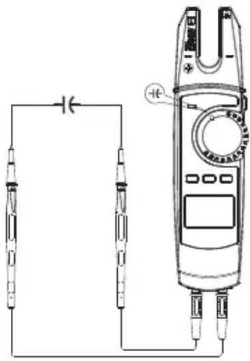
- Allumez l'appareil avec le bouton rotatif (3), et sélectionnez la gamme de mesure
- Appuyez sur la touche SELECT (9) pour sélectionner la gamme de mesure pour la mesure de capacité +← apparaît sur l'écran à CL.
- Enfichez le conducteur de mesure rouge dans la prise de mesure V (6) et le conducteur de mesure noir dans la prise de mesure COM (7).
- Reliez les pointes de mesure au condensateur à mesurer. La pointe de mesure rouge correspond au pôle positif, la pointe de mesure noire au pôle négatif. Respectez la polarité : La capacité s'affiche à l'écran après un court instant. Attendez que la valeur affichée se stabilise.
- L'affichage de
- (pour overload = dépassement) sur l'écran LCD indique que vous avez dépassé la plage de mesure ou que le circuit de mesure est interrompu.
- Une fois la mesure terminée, enlevez la pince et éteignez-la.
→ Avec des conducteurs de test « ouverts », il peut arriver qu'une valeur plus basse s'affiche sur l'écran LCD en raison de la sensibilité de l'entrée de mesure.
i) Détection de tension alternative sans contact (NCV)

Le détecteur de tension ne sert qu'à effectuer des tests rapides et ne saurait se substituer à un contrôle de tension avec contact. Cette méthode de vérification, permettant de tester l'absence de tension afin d'effectuer certains travaux, n'est pas autorisée.
Grâce à la fonction de détection NCV (Non Contact Voltage Detection), la présence de tension alternée sur les conducteurs est détectée sans contact. Le capteur NCV est fixé à la pointe de la pince ampèremétrique.
D'abord, testez toujours la fonction NCV sur une source de tension CA connue afin d'éviter toute erreur de détection. En cas d'erreur de détection, il y a risque de décharge électrique.
Procédez comme suit :
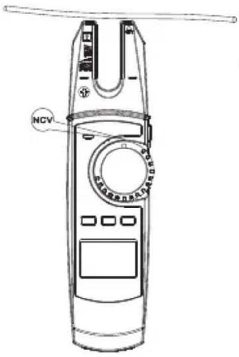
- Tant qu'aucune tension alternative n'est détectée, le message « EF » s'affiche sur l'écran LCD.
- Si une tension alternative ≥100 V/CA rms est détectée à une distance de mesure <10 mm, les tonalités d'alarme commencent à retentir et l'affichage du signal NCV (11) commence à clignoter rapidement.
- En fonction de la tension alternative détectée, l'intensité de la tension détectée est indiquée par 4 symboles «—», «—», «—» ou «—». L'intensité de la tension détectée augmente avec le nombre de tirets.
- Une fois la mesure terminée, enlevez la pince et éteignez-la.
À cause de l'extrême sensibilité du capteur NCV (11), l'affichage du signal NCV peut s'allumer également en présence de recharges statiques. Ce phénomène est normal et n'indique pas un dysfonctionnement.
10. Fonctions supplémentaires
a) Mise hors tension automatique
- Quand le bouton rotatif et les autres touches ne sont pas activés pendant 15 minutes, l'appareil s'éteint automatiquement. Cette fonction protège et préserve les piles et permet aussi de prolonger la durée de fonctionnement. Pour la remise en marche, appuyez sur une touche de l'appareil ou placez le commutateur rotatif sur la position OFF, rallumez la pince ampèremétrique, puis sélectionnez à nouveau la fonction de mesure souhaitée.
b) Éclairage
c) Fonction HOLD
d) Fonction lampe de poche
La fonction lampe de poche ne fonctionne que lorsque l'appareil de mesure est allumé.
11. Maintenance

Contrôlez régulièrement la sécurité technique de l'appareil et des conducteurs de test en vous assurant de l'absence d'endommagements au niveau du boîtier ou d'écrasement, etc.
12. Entretien et nettoyage
Avant de procéder au nettoyage, il est impératif de prendre connaissance des consignes de sécurité suivantes.

N'utilisez jamais de nettoyants agressifs, d'alcool de nettoyage ou de solutions chimiques car ces produits pourraient attaquer le boîtier ou nuire au bon fonctionnement de l'appareil.
L'ouverture des couvercles ou le démontage de pièces risquent de mettre à nu des pièces sous tension, sauf lorsqu'il est possible d'effectuer ces procédures manuellement.
Avant toute opération de nettoyage ou d'entretien, il convient de débrancher les câbles de l'appareil et de tous les objets mesurés. Éteignez la pince.
13. Élimination des déchets
a) Produit
Les appareils électroniques sont des matériaux recyclables et ne doivent pas être éliminés avec les ordures ménagères. En fin de vie, éliminez l'appareil conformément aux dispositions légales en vigueur. Retirez éventuellement les piles insérées et recyclez-les séparément du produit.
b) Piles
Le consommateur final est légalement tenu de recycler toutes les piles (ordonnance relative à l'élimination des piles usagées) ; il est interdit de les jeter avec les ordures ménagères.
Les piles qui contiennent des substances toxiques sont porteuses du symbole ci-contre indiquant l'interdiction de les jeter avec les ordures ménagères. Les désignations pour le métal lourd prépondérant sont : Cd = cadmium, Hg = mercure, Pb = plomb (la désignation figure sur les piles, par ex. sous le symbole de poubelle ci-contre).
Vous pouvez rapporter gratuitement vos piles usagées aux centres de recyclage de votre commune, à nos succursales ou à tous les points de vente de piles.
Vous respectez ainsi les ordonnances légales et contribuez à la protection de l'environnement.
14. Données techniques
a) Pince ampèremétrique
Alimentation en électricité......2 piles AA de 1,5 V/CC
Catégories de mesure ....CAT II 1000 V, CAT III 600 V
Fonction d'arrêt....après environ 15 minutes
Largeur d'ouverture de la
pince ampèremétrique ....14,7 mm maxi
Écran LCD ....max. 6000 points (caractères)
Durée de vie des piles....45 à 130 heures en fonctionnement normal
Indicateur de niveau des piles ..... lorsque ≤ 2,4 V
Impédance d'entrée......DCV (≥10 MΩ)
Conditions de service .... 0 à 30 °C ; < 80 %
$$ +30\text{à} +40^{\circ}\mathrm{C}, < 75\% $$
$$ +40\text{à} +50^{\circ}\mathrm{C}, < 45\% $$
humidité relative de l'air (sans condensation)
Conditions de stockage ......de -20 à +60 °C, < 80 %
Altitude de fonctionnement......2000 m max.
Dimensions (I x H x P)....environ 209 x 53 x 35 mm
Poids....env. 184 g (sans accessoire) env. 410 g (avec accessoire)
b) Tolérances de mesure
Courant alternatif
| Plage Résolution Précision | |
| 200 A 0,1 A ±(2,5 % + 5) | |
| Protection contre les surcharges : 750 V/CA, 200 A ; Gamme de fréquence : 50 - 60 Hz | |
Courant continu
| Plage Résolution Précision | ||
| 200 A 0,1 A ±(2,5 % + 5) | ||
| Protection contre les surcharges : 1000 V/DC, 200 APrécision DC : Après une position zéro DC réussie (ZERO) | ||
Tension alternative
| Plage Résolution Précision | ||
| 6,0 V 0,001 V ±(1,2 % + 5) | ||
| 60,0 V 0,01 V | ||
| 600,0 V 0,1 V | ±(1,2 % + 3) | |
| 750 V | 1 V | ±(1,5 % + 5) |
| Gamme de fréquence : 45 - 400 Hz ; si < 400 mV : 50 - 100 Hz, protection contre la surcharge : 750 V/CA ; impédance : >10 MΩ | ||
Tension continue
| Plage Résolution Précision | ||
| 6,0 V 0,001 V ±(0,8 % + 3) | ||
| 60,0 V 0,01 V ±(0,8 % + 3) | ||
| 600,0 V 0,1 V ±(0,8 % + 3) | ||
| 1000,0 V 1 V ±(1 % + 5) | ||
| Protection contre les surcharges : 1000 V/CC, 200 A ; Impédance : >10 MΩ | ||
Résistance
| Plage Résolution Précision | |
| 600,0 Ω 0,1 Ω ±(1,2 % + 2) | |
| 6,00 kΩ 0,001 kΩ ±(1,0 % + 2) | |
| 60,00 kΩ 0,01 kΩ ±(1,0 % + 2) | |
| 600,00 kΩ 0,1 kΩ ±(1,0 % + 2) | |
| 6,00 MΩ 0,001 MΩ ±(1,2 % + 2) | |
| 60,00 MΩ 0,01 MΩ ±(1,5 % + 5) | |
| Protection contre les surcharges : 1000 V/CC, 750 V/CC; 200 A | |
Capacité
| Plage Résolution Précision | ||
| 60,00 nF 0,01 nF ±(4 % + 20) | ||
| 600,00 nF | 0,1 nF | ±(4 % + 20) |
| 6,00 μF | 0,001 μF | |
| 60,00 μF 0,01 μF | ||
| 600,00 μF | 0,1 μF | |
| 6,000 mF | 0,001 mF | ± 10 % |
| 60,00 mF | 0,01 mF | Uniquement à titre d'information ! |
| Protection contre les surcharges : 1000 V/CC ; 750 V/CA | ||
Test de diodes
| Plage Résolution Précision | ||
| 6,00 V 0,001 V 0,5 - 0,8 V | ||
| Protection contre les surcharges : 1000 V/CC, 750 V/CA, 200 A, tension de test 3,3 V. | ||
Essai de continuité acoustique
| Plage Résolution Précision | ||
| 600,00 Ω 0,1 Ω <10 Ω tonalité continue <10 Ω tonalité continue | >100 Ω (pas de son) | |
| Protection contre les surcharges : 1000 V/CC, 750 V/CA, 200 A, tension de test 1,2 V. | ||
Mesure de tension sans contact
| Plage Distance | |
| 100 - 750 V/CA Si <10 mm : Tonalité continue et la LED clignote | |
Pagina
a) Symbolen die voorkomen in de gebruiksaanwijzing....94
b) Symbolen op het product 95
a) Algemeen....98
b) Aangesloten apparaten....99
c) Batterijen....99
d) Personen en product....99
a) Stroomtang....101
b) Symbolen op het lcd-display 102
a) Batterijen plaatsen....103
b) Batterijen vervangen ....104
a) Aan-/uitzetten / meetfunctie kiezen 105
b) Relatieve meting....106
c) Stroommeting "A"....106
d) Spanningsmeting "V"....109
e) Meten van de weerstand....111
f) Continuïteitstest....111
g) Diodetest....113
h) Capaciteitsmeting....113
i) Contactloze wisselspanningsdetectie "NCV"....114
a) Automatische uitschakeling....115
b) Verlichting....116
c) HOLD-functie....116
d) Zaklampfunctie....116
a) Product....118
b) Batterijen....118
a) Stroomtang....118
b) Meettolerantie....119
1. Inleiding
Geachte klant,
Hartelijk dank voor de aankoop van dit product.
Het product voldoet aan alle wettelijke, nationale en Europese normen.
Om dit zo te houden en een veilig gebruik te garanderen, dient u als gebruiker de aanwijzingen in deze gebruiksaanwijzing op te volgen.

Deze gebruiksaanwijzing behoort bij dit product. Er staan belangrijke aanwijzingen in over de ingebruikname en het gebruik. Houd hier rekening mee als u dit product doorgeeft aan derden. Bewaar deze gebruiksaanwijzing daarom voor later gebruik!
Bij technische vragen kunt u zich wenden tot onze helpdesk.
Voor meer informative kunt u kijken op www.conrad.nl of www.conrad.be
2. Verklaring van de symbolen
a) Symbolen die voorkomen in de gebruiksaanwijzing
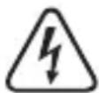
Het symbool met een bliksemschicht in een driehoek wordt gebruikt als er gevaar voor uw gezondheid bestaat bijv. door elektrische schokken.

Het pictogram met het uitroepteken in een driehoek wijst op belangrijke aanwijzingen in deze gebruiksaanwijzing die in ieder geval nageleefd moeten worden.
U ziet het pijl-symbol waar bijzondere tips en aanwijzingen over de bediening worden gegeven.
b) Symbolen op het product
Symbool Betekenis
| Dit symbool geeft aan dat dit product volgens veiligheidsklasse II is opgebouwd. Hij heeft versterkte of dubbele isolatie tussen stroomcircuit en uitgangsspanning. | |
| ≡ | Aardpotentiaal |
| ⚠️ | Het symbool met een bliksemschicht in een driehoek wordt gebruikt als er gevaar voor uw gezondheid bestaat bijv. door elektrische schokken. |
| ~ | Wisselspanning |
| == | Gelijkspanning |
| -▶▶ | Akoestische signalen aan/uit |
| ▶◀ | Diode |
| ◀◀ | Symbool voor het capaciteitsmeetbereik |
| Een symbool met een vierkant staat het meten van de stroom aan niet-ge-isoleerde, gevaarlijk-actieve stroomkabels toe en waarschuwt voor de mogelijke gevaren. U dient gebruik te maken van een persoonlijke veilig-heidsuitrusting. | |
| CE | Dit apparaat is CE-conform en voldoet aan de noodzakelijke Europese richtlijnen. |
| CAT II | Meetcategorie II voor metingen aan elektrische en elektronische apparaten die met behulp van een stekker direct zijn aangesloten op het elektrische stroomnet. Onder deze categorie vallen ook alle lagere categorieën (bijv. CAT I voor het meten van signaal- en stuurspanningen). |
| CAT III | Meetcategorie III voor metingen aan installaties in gebouwen (bijv. stop-contacten of groepen). Onder deze categorie vallen ook alle lagere categorieën (bijvoorbeeld CAT II voor metingen aan elektrische apparaten). Het uitvoeren van metingen in CAT III is alleen toegestaan met behulp van meetpennen met een maximale blootgestelde contactlengte van 4 mm of meetpennen met afdekdoppen. |
| ⊕ | Polariteitsmarkering (pluspool) voor gelijkstroommeting. De symbolen ge-ven de stroomrichting weer om te kunnen meten met de juiste polariteit. |
3. Doelmatig gebruik
Stroomtang voor het meten en weergeven van de elektrische parameters in het bereik van overspanningscategorie CAT II tot max. 1000 V en CAT III tot max. 600 V tegen aardingspotentieel, volgens EN 61010-1, EN 61010-2-032, EN 61010-2-033 en alle lagere categorieën.
Metingen onder ongunstige omstandigheden zijn niet toegestaan. Ongunstige omgevingsomstandigheden zijn:
Gebruik om te meten alleen meetkabels die afgestemd zijn op de specificaties van het meetapparaat.
Gebruik het apparaat alleen met het aangegeven batterijtype.
Het meetapparaat mag niet gebruikt worden in geopende toestand, met geopend batterijvak of met ontbrekende batterijvakdeksel.
Het product is alleen bedoeld voor gebruik in gesloten ruimtes, dus gebruik buitenshuis is niet toegestaan. Contact met vocht, bijv. in badkamers e.d. dient absoluut te worden vermeden.
In verband met veiligheid en normering zijn geen aanpassingen en/of wijzigingen aan dit product toegestaan. Als het product voor andere doeleinden wordt gebruikt dan de hiervoor beschreven doeleinden, kan het product beschadigd raken. Bovendien kan bij verkeerd gebruik een gevaarlijke situatie ontstaan met als gevolg bijvoorbeeld kortsluiting, brand, elektrische schok etc. Lees de gebruiksaanwijzing zorgvuldig door en bewaar deze goed. Geef het product alleen samen met de gebruiksaanwijzing door aan derden.
Alle vermelde bedrijfs- en productnamen zijn handelsmerken van de respectievelijke eigenaren. Alle rechten voorbehouden.
4. Leveringsomvang
- Gebruiksaanwijzing
Actuele gebruiksaanwijzingen
Download de meest recente gebruiksaanwijzing via de link www.conrad.com/downloads of scan de afgebeelde QR-Code. Volg de instructies op de website.
5. Eigenschappen en functies
Lees de gebruiksaanwijzing zorgvuldig door en let vooral op de veiligheidsinstructies. Als u de veiligheidsinstructies en de aanwijzingen voor een juiste bediening in deze gebruiksaanwijzing niet opvolgt, kunnen wij niet aansprakelijk worden gesteld voor het daardoor ontstane persoonlijke letsel of schade aan voorwerpen. Bovendien vervalt in dergelijke gevallen de aansprakelijkheid/garantie.
a) Algemeen
b) Aangesloten apparaten
- Neem ook de veiligheidsaanwijzingen en gebruiksaanwijzingen in acht van de overige apparaten, waarop het product wordt aangesloten.
c) Batterijen
d) Personen en product
7. Bedieningselementen en symbolen
a) Stroomtang
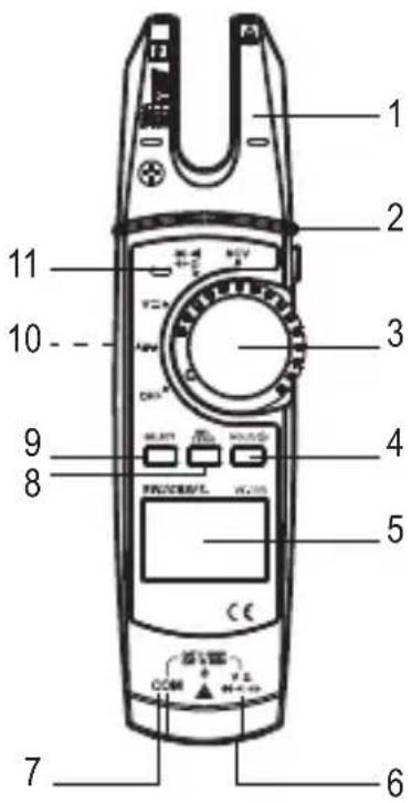
1 Stroomtang
2 Zaklampknop
3 Draaischakelaar om de gewenste meetfunctie te kiezen
4 Knop HOLD/
5 Lcd-display
6 V-meetbus (
7 COM-meetbus
8 Knop REL ZERO
9 Knop SELECT
10 Batterijvak (achterkant)
11 NCV-signaalaanduiding


b) Symbolen op het Icd-display
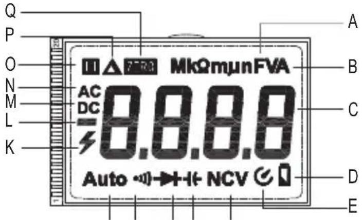
FGHIJ
Nr. Symbool Verklaring
| A Ω | Ohm (eenheid van elektrische weerstand) | |
| kΩ, MΩ | Kilo-ohm (exp.3), mega-ohm (exp.6) | |
| Hz | Hertz (eenheid van elektrische frequentie) | |
| mV | Millivolt (exp.-3) | |
| mA, μA | Milliampère (exp.-3), Microampère (exp.-6) | |
| nF | Nanofarad (exp-9; eenheid van elektrische capaciteit) | |
| μF | Microfarad (exp.-6) | |
| mF | Millifarad (exp.-3) |
B V A Volt (eenheid van elektrische spanning)
Ampère (eenheid voor elektrische stroom)
C - Meetwaarde-weergave
D Capaciteit batterij
E Automatische uitschakeling
F NCV Contactloze herkenning wisselspanning
G Symbol voor capaciteit
H Symbool-voor de diodetest
I ••) Symbool voor akoestische continuïteitscontrole
J Auto Automatische meetbereikkeuze is actief
Nr. Symbool Verklaring
K Bliksemsybool voor spanningsmeting
L + - Weergave van het voorteken van de meetwaarde
M DC Gelijkspanning/-stroom
N AC Wisselspanning/-stroom
O HOLD-fu#e is actief als het symbool wordt weergegeven
P Relatieve meting is ingesteld
Q Nulinste ZERO
8. Plaatsen/vervangen van de batterijen
a) Batterijen plaatsen
Bij levering bevat het product normaalgesproken geen batterijen. Gebruik van accu's wordt in verband met hun lagere spanning afgeraden.
Volg de hierna beschreven stappen om het product in gebruik te nemen.
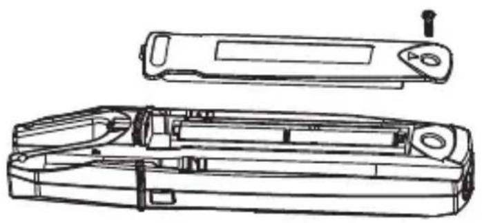
natural_image
Technical line drawing of a device casing with internal components and a top view (no text or symbols)Afb. 1
b) Batterijen vervangen
Het vervangen van de batterij is noodzakelijk als op het lcd-display (5) het symbool 📋D) oplicht of de achtergrondverlichting nog zwak of helemaal niet meer brandt. Vervang de batterijen zo snel mogelijk als beschreven in paragraaf a) Batterijen plaatsen. Ziet u bij het aanzetten alleen het symbool 📋vervang de batterijen dan onmiddellijk.
9. Meten
Zorg dat de max. toegestane ingangswaarden in geen geval worden overschreden. Raak geen schakelingen of delen daarvan aan als daar hogere spanningen dan 33 V/Acrms of 42 V/DC op kunnen staan! Levensgevaar!

De maximale toegestane spanning in de te meten stroomkring ten opzichte van het aardpotentiaal mag de 1000 V in CAT II of 600 V in CAT III niet overschrijden.
Controleer vóór begin van elke meting alle verbonden meetkabels op schade, bijvoorbeeld scheuren, barsten of knikken. Defecte meetkabels mogen niet meer worden gebruikt! Levensgevaar!
Pak de meetpennen tijdens het meten niet vast boven de voelbare handgreepmarkeringen.
Verbind alleen de twee meetkabels met het meetapparaat die voor het meten nodig zijn. Ontkoppel wanneer u stroommetingen uitvoert uit veiligheidsoverwegingen alle meetkabels die u niet nodig heeft, van het meetapparaat.
Het meten van stroomkringen > 33 V/AC en > 42 V/DC mag alleen worden uitgevoerd door een vakman en door personen die vertrouwd zijn met de geldende voorschriften en alle daaruit voortvloeiende mogelijke gevaren.
Houd voor uw eigen veiligheid rekening met alle relevante veiligheidsinstructies, voorschriften en veiligheidsmaatregelen.
De meetwaarden worden weergegeven op het lcd-display (5) van de stroomtang. De polariteit wordt bij negatieve meetwaarden automatisch met het teken (-) weergegeven.
→ Verschijnt < OL > (voor Overload) in het lcd-display (5), dan heeft u het meetbereik overschreden.
→ Transportbeveiligingskappen bevinden zich op de stekkers van de meegeleverde meetkabels. Verwijder deze voordat u de stekkers van de meetsnoeren in de bussen steekt.
a) Aan-/uitzetten / meetfunctie kiezen
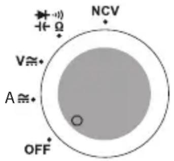
Afb. 2
- Sommige meetfuncties moeten met behulp van de knop SELECT (9) worden ingesteld. Lees hiervoor in de betreffende hoofdstukken.
Belangrijk! Zorg er voor iedere meting voor dat u de juiste meetfunctie hebt ingesteld.
- Bij het indrukken van een knop of de draaischakelaar klinkt een pieptoon. Bij een ongeldige werking geeft de zoemer twee tonen af.
b) Relatieve meting
U kunt meetwaarden absoluut meten (normale meetmodus) of een waarde in verhouding tot de voorgaande meten.
c) Stroommeting "A"
De multimeter is voorzien van een stroomtang (1) voor contactloze stroommetingen. De sensoren in de stroomtang detecteren het magnetisch veld rond de geleiders waar een stroom doorheen loopt.
Zorg dat de geleider zich altijd in het midden van de tang bevindt (let op de pijlmarkeringen).
Klem de stroomtang altijd alleen om één stroomgeleider.
Meten van wisselstroom A ≈
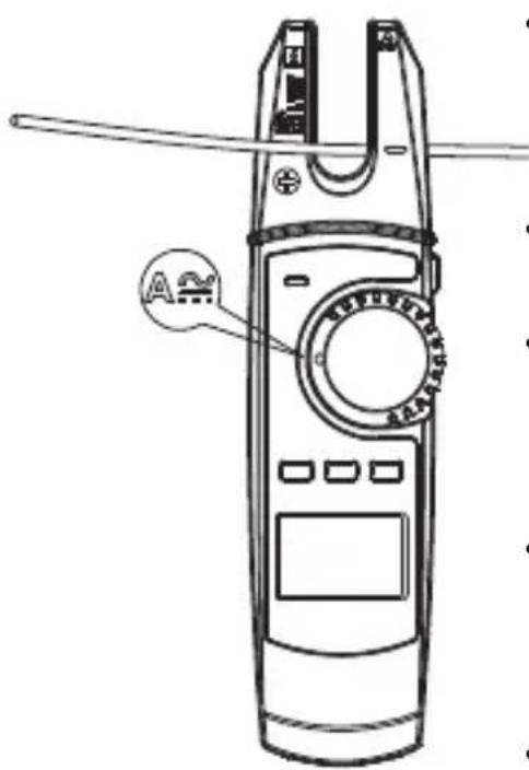
Meten van gelijkstroom A met nulinstelling
Door de hoge gevoeligheid en het omringend magnetisch veld (i.e. het magnetisch veld van de aarde, etc.) wordt in het gelijkstroom-meetbereik, zelfs als de tang gesloten is, altijd een lage stroomsterkte op het display aangegeven. Zet direct voor iedere meting of wanneer van stroom-kabel wordt gewisseld, de weergave handmatig op nul. Ga voor de nulinstelling als volgt te werk:
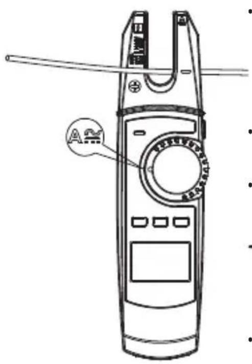
Zodra bij het meten van gelijkstroom een minteken "-" voor de gemeten waarde verschijnt, loopt de stroom in tegengestelde richting (of is de stroomtang omgedraaid).
d) Spanningsmeting "V"
Meting van wisselspanningen "AC" (V)
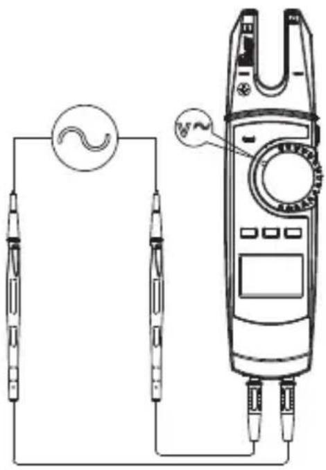
Bij het overschrijden van een spanning van 30 V/AC geeft het lcd-display een visuele hoogspanningswaarschuwing weer om te waarschuwen voor het gevaar van elektrische schokken.
- Verwijder na het afsluiten van de meting de stroomtang van het meetobject en schakel het product uit.
Meting van gelijkspanningen "DC" (V.
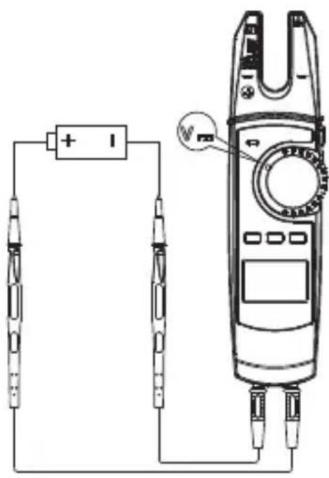
Bij het overschrijden van een spanning van 42 V/DC geeft het lcd-display een visuele hoogspanningswaarschuwing weer om te waarschuwen voor het gevaar van elektrische schokken.
- De actuele meetwaarde wordt samen met de desbetreffende polariteit weergegeven op het display.
Wanneer er bij gelijkspanning voor de meetwaarde een "-" (min)-teken verschijnt, is de gemeten spanning negatief (of de meetkabels zijn verwisseld).
- Meet geen spanningen van meer dan 1000 V/DC. Bij het overschrijden van het meetbereik (1000 V/DC) hoort u geluidssignalen.
- Verwijder na het afsluiten van de meting de stroomtang van het meetobject en schakel het product uit.
e) Meten van de weerstand

Controleer of alle te meten onderdelen van de schakeling, schakelingen en componenten evenals andere te meten objecten volledig spanningsloos en ontladen zijn.
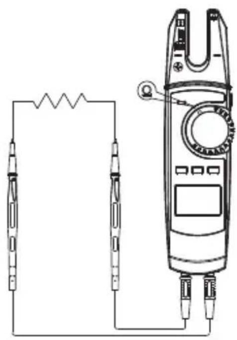
natural_image
Pure electrical circuit lines without any symbols
Houd voor het meten in het meetbereik van 600 Ω de meetpennen samen om ze kort te sluiten. Druk op de knop REL ZERO (8), om de waarde terug te zetten. Dit compenseert de invloed van de weerstand van de meetpennen.
Bij het meten van weerstand moet u erop letten dat de meetpunten waarmee de meetpennen in contact komen vrij zijn van vuil, olie, soldeerhars en dergelijke. Dergelijke omstandigheden kunnen het meetresultaat beïnvloeden.
f) Continuiteitstest

Controleer of alle te meten onderdelen van de schakeling, schakelingen en componenten evenals andere te meten objecten (bijv. condensatoren) volledig spanningsloos en ontladen zijn.
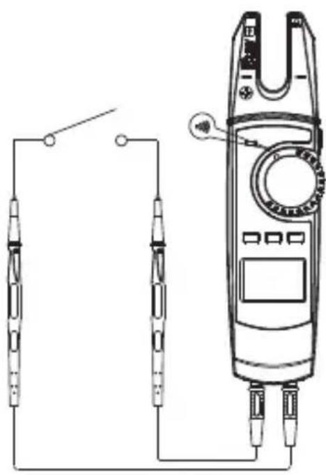
natural_image
Pure electrical circuit lines without any symbols- Schakel het meetapparaat in met behulp van de draaischakelaar (3) en selecteer het meetbereik
- Druk op de knop SELECT (9) om het meetbereik voor continuïteitstest - te kiezen. Op het lcd-display verschijnt -
- Steek de rode meetkabel in de V-meetbus (6) en de zwarte meetkabel in de COM-meetbus (7).
- Sluit nu de beide meetpennen aan op het te meten object (batterij, schakeling enz.). Het rode meetpunt staat voor de pluspool, het zwarte meetpunt staat voor de minpool.
- Als de gemeten weerstandswaarde minder dan 10 ohm bedraagt, klinkt er continu een akoestische melding, als deze tussen 10 en 100 ohm klinkt, klinkt er mogelijk een geluid, of ook niet. Bij meer dan 1000 ohm wordt geen akoestische melding weergegeven.
- Verwijder na het afsluiten van de meting de stroomtang van het meetobject en schakel het product uit.
g) Diodetest

Controleer of alle te meten onderdelen van de schakeling, schakelingen en componenten evenals andere te meten objecten (bijv. condensatoren) volledig spanningsloos en ontladen zijn.
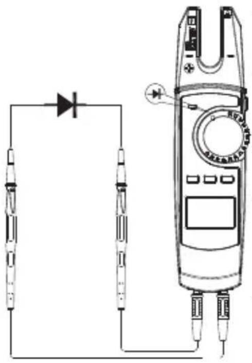
natural_image
Pure electrical circuit lines without any symbols
Om de nauwkeurigste meetresultaten te verkrijgen, is het raadzaam onderdelen uit de schakelingen te verwijderen.
h) Capaciteitsmeting

Controleer dat alle te meten schakelcomponenten, schakelingen en bouwelementen evenals andere meetobjecten absoluut spanningsloos en ontladen zijn.
Houd bij elektrolytische condensatoren absoluut rekening met de juiste polariteit.
Bij capaciteitsmetingen in het bereik van 60 nF wordt een nulinstelling aanbevolen om de weerstand van de meetkabels te compenseren. Druk daartoe kort op de knop REL ZERO (8).
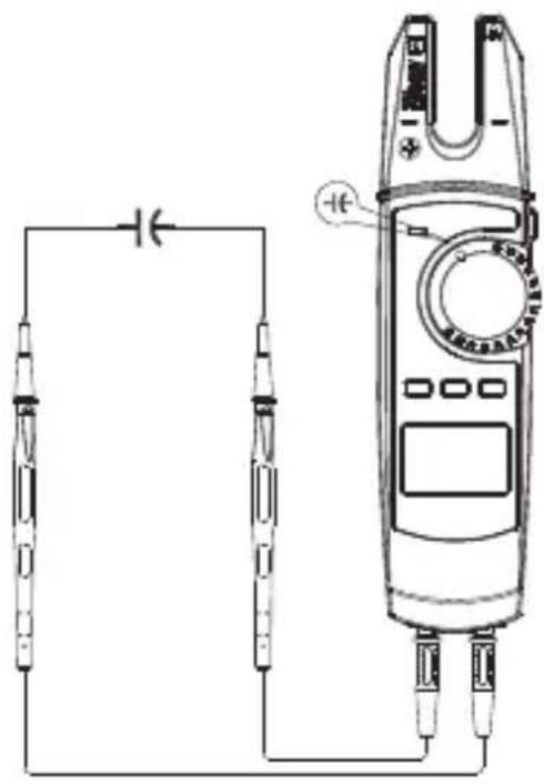
natural_image
Pure electrical circuit lines without any symbols- Schakel het meetapparaat in met behulp van de draaischakelaar (3) en selecteer het meetbereik
- Druk op de knop SELECT (9) om het meetbereik voor de capaciteitsmeting -kiezen. Op het lcd-display verschijnt
- Steek de rode meetkabel in de V-meetbus (6) en de zwarte meetkabel in de COM-meetbus (7).
- Sluit de beide meetpennen aan op de te meten condensator. Het rode meetpunt staat voor de pluspool, het zwarte meetpunt staat voor de minpool. Let op de polariteit. Het display geeft na een korte periode de capaciteit weer. Wacht totdat de waarde op het display zich heeft gestabiliseerd.
- Wanneer < OL > (voor overload) in het lcd-display verschijnt, heeft u het meetbereik overschreden of is het meetcircuit onderbroken.
- Verwijder na het afsluiten van de meting de stroomtang van het meetobject en schakel het product uit.
Vanwege de hoge gevoeligheid van de meetingang, kan het in geval van "open" meetkabels enige tijd duren voordat de waarde op het lcd-display verschijnt.
i) Contactloze wisselspanningsdetectie "NCV"

De spanningsdectector is alleen bedoeld voor snelle tests en vervangt in geen geval een spanningscontrole met contact. Deze methode is niet toegestaan voor het vaststellen van spanningsloosheid zodat bepaald werk uitgevoerd kan worden.
De NCV-functie (Non-Contact-Voltage-Detection = contactloze spanningsdetectie) wordt gebruikt om contactloos te bepalen of er wisselspanning op geleiders staat. De NCV-sensor is aangebracht aan de punt van de stroomtang.
Test de NCV-functie eerst op een bekende AC-spanningsbron om foutieve metingen te vermijden. Bij een foutieve detectie bestaat het risico op een elektrische schok.
Ga als volgt te werk:
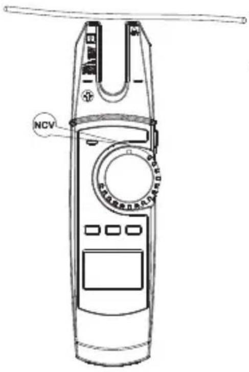
Door de grote gevoeligheid van de NCV-sensor kan de NCV-signaalaanduiding (11) ook bij statische ladingen verschijnen. Dit is normaal en geen defect.
10. Extra functies
a) Automatische uitschakeling
- Het meetapparaat schakelt zich na 15 minuten automatisch uit, als geen knop of draaischakelaar wordt bediend. Deze functie beschermt en spaart de batterijen en verlengt de gebruiksduur. Voor het opnieuw inschakelen, drukt u op een knop van het apparaat of zet u de draaischakelaar in de stand OFF en selecteert u vervolgens opnieuw de gewenste meetfunctie.
b) Verlichting
c) HOLD-functie
d) Zaklampfunctie
De zaklampfunctie werkt alleen als het meetapparaat is ingeschakeld.
11. Onderhoud

Controleer regelmatig de technische veiligheid van het apparaat en de meetkabels, bijv. op beschadiging van de behuizing of afknellen van de draden.
12. Onderhoud en reiniging
Voordat u het apparaat reinigt, dient u absoluut de volgende veiligheidsinstructies in acht te nemen:

Gebruik in geen geval agressieve schoonmaakmiddelen, schoonmaakalcohol of andere chemische oplossingen, aangezien die de behuizing kunnen aantasten of de goede werking kunnen schaden.
Bij het openen van afdekkingen of het verwijderen van onderdelen, behalve als dit met de hand mogelijk is, kunnen onder spanning staande onderdelen blootgelegd worden.
Voor een reiniging of reparatie moeten de aangesloten kabels van de meetapparatuur en van alle meetobjecten worden gescheiden. Schakel de stroomtang uit.
- Gebruik voor de reiniging geen schurende reinigingsmiddelen, benzine, alcohol of dergelijke. Dit beschadigt het oppervlak. Gebruik voor het schoonmaken ook geen werktuigen met scherpe kanten, schroevendraaiers of metalen borstels.
- Reinig de stroomtang en de meetkabels altijd met een schone, pluisvrije, antistatische en licht vochtige doek. Laat het apparaat volledig drogen voordat u het voor de volgende meting gaat gebruiken.
13. Verwijdering
a) Product
Elektronische apparaten zijn recyclebare stoffen en horen niet bij het huisvuil. Voer het product aan het einde van zijn levensduur volgens de geldende wettelijke bepalingen af. Verwijder de eventueel geplaatste batterijen en gooi deze afzonderlijk van het product weg.
b) Batterijen
U bent als eindverbruiker volgens de KCA-voorschriften wettelijk verplicht alle lege batterijen in te leveren; weggooien met het huisvuil is niet toegestaan.
Batterijen die schadelijke stoffen bevatten, zijn gemarkeerd met nevenstaand symbool. Deze mogen niet via het huisvuil worden afgevoerd. De aanduidingen voor de zware metalen die het betreft zijn: Cd = cadmium, Hg = kwik, Pb = lood (de aanduiding staat op de batterijen, bijv. onder de links afgebeelde vuilnisbaksymbool).
U kunt verbruikte batterijen gratis bij de verzamelpunten van uw gemeente, onze filialen of overal waar batterijen worden verkocht, afgeven.
U voldoet daarmee aan de wettelijke verplichtingen en draagt bij aan de bescherming van het milieu.
14. Technische gegevens
a) Stroomtang
Stroomvoorziening....2 x 1,5 V (AA) batterij
Meetcategorieën.....CAT II 1000 V, CAT III 600 V
Uitschakelfunctie .....na ca. 15 minuten
Openingsbereik stroomtang ......max. 14,7 mm
Lcd-display ....max. 6000 counts (tekens)
Levensduur batterij....45 - 130 uur bij normaal gebruik
Batterij-indicator......bij ≤2,4 V
Ingangsimpedantie ....DCV (≥10 MΩ)
| Bedrijfscondities | 0 tot 30 °C; <80 % |
| +30 tot +40 °C, <75 % | |
| +40 tot +50 °C, <45 % | |
| relatieve luchtvochtigheid (niet condenserend) |
Opslagcondities....-20 tot +60 °C, <80 %
Gebruikshoogte ....max. 2000 m
Afmetingen (B x H x D)......ca. 209 x 53 x 35 mm
Gewicht..... ca. 184 g (zonder toebehoren) resp. 410 g (met toebehoren)
b) Meettolerantie
Wisselstroom
| Bereik Resolutie Nauwkeurigheid | |
| 200 A 0,1 A ± (2,5 % + 5) | |
| Overbelastingsbeveiliging: 750 V/AC, 200 A; frequentiebereik: 50 - 60 Hz | |
Gelijkstroom
| Bereik Resolutie Nauwkeurigheid | |
| 200 A 0,1 A ± (2,5 % + 5) | |
| Overbelastingsbeveiliging: 1000 V/DC, 200 AGelijkstroomnauwkeurigheid: Na gedane gelijkstroomnulstelling (ZERO) | |
Wisselspanning
| Bereik Resolutie Nauwkeurigheid | ||
| 6,0 V 0,001 V ± (1,2 % + 5) | ||
| 60,0 V 0,01 V | ||
| 600,0 V 0,1 V | ± (1,2 % + 3) | |
| 750 V | 1 V | ± (1,5 % + 5) |
| Frequentiebereik: 45 - 400 Hz; als <400 mV: 50 - 100 Hz; Overbelastingsbeveiliging: 750 V; Impedantie: >10 MΩ | ||
Gelijkspanning
| Bereik Resolutie Nauwkeurigheid | |
| 6,0 V 0,001 V ± (0,8 % + 3) | |
| 60,0 V 0,01 V ± (0,8 % + 3) | |
| 600,0 V 0,1 V ± (0,8 % + 3) | |
| 1000,0 V 1 V ± (1 % + 5) | |
| Overbelastingsbeveiliging: 1000 V/DC, 200 A; impedantie: >10 MΩ | |
Weerstand
| Bereik Resolutie Nauwkeurigheid | |
| 600,0 Ω 0,1 Ω ± (1,2 % + 2) | |
| 6,00 kΩ 0,001 kΩ ± (1,0 % + 2) | |
| 60,00 kΩ 0,01 kΩ ± (1,0 % + 2) | |
| 600,00 kΩ 0,1 kΩ ± (1,0 % + 2) | |
| 6,00 MΩ 0,001 MΩ ± (1,2 % + 2) | |
| 60,00 MΩ 0,01 MΩ ± (1,5 % + 5) | |
| Overbelastingsbeveiliging: 1000 V/DC, 750 V/DC; 200 A | |
Capaciteit
| Bereik Resolutie Nauwkeurigheid | ||
| 60,00 nF | 0,01 nF | ± (4 % + 20) |
| 600,00 nF 0,1 nF | ||
| 6,00 μF | 0,001 μF | ± (4 % + 20) |
| 60,00 μF | 0,01 μF | |
| 600,00 μF | 0,1 μF | |
| 6,000 mF 0,001 mF ± 10 % | ||
| 60,00 mF 0,01 mF Alleen ter informatie. | ||
| Overbelastingsbeveiliging: 1000 V/DC; 750 V/AC | ||
Diodetest
| Bereik Resolutie Nauwkeurigheid | |
| 6,00 V 0,001 V 0,5 - 0,8 V | |
| Overbelastingsbeveiliging: 1000 V/DC, 750 V/AC, 200 A, testspanning ca. 3,3 V | |
Akoestische continuiteitstest
| Bereik Resolutie Nauwkeurigheid | |
| 600,00 Ω 0,1 Ω <10 Ω continue toon <10 Ω Continue toon | >100 Ω (geen toon) |
| Overbelastingsbeveiliging: 1000 V/DC, 750 V/AC, 200 A, testspanning ca. 1,2 V | |
Contactloze spanningsmeting
| Bereik Afstand | |
| >100 - 750 V/AC Bij <10 mm: Continue toon en led knippert | |
D Dies ist eine Publikation der Conrad Electronic SE, Klaus-Conrad-Str. 1, D-92240 Hirschau (www.conrad.com).
Alle Rechte einschließlich Übersetzung vorbehalten. Reproduktionen jeder Art, z.B. Fotokopie, Mikroverfilmung, oder die Erfassung in elektronischen Datenverarbeitungsanlagen, bedürfen der schriftlichen Genehmigung des Herausgebers. Nachdruck, auch auszugsweise, verboten. Die Publikation entspricht dem technischen Stand bei Drucklegung.
Copyright 2020 by Conrad Electronic SE.
This is a publication by Conrad Electronic SE, Klaus-Conrad-Str. 1, D-92240 Hirschau (www.conrad.com).
All rights including translation reserved. Reproduction by any method, e.g. photocopy, microfilming, or the capture in electronic data processing systems require the prior written approval by the editor. Reprinting, also in part, is prohibited. This publication represent the technical status at the time of printing.
Copyright 2020 by Conrad Electronic SE.
Ceci est une publication de Conrad Electronic SE, Klaus-Conrad-Str. 1, D-92240 Hirschau (www.conrad.com).
Tous droits réservés, y compris de traduction. Toute reproduction, quelle qu'elle soit (p. ex. photocopie, microfilm, saisie dans des installations de traitement de données) nécessite une autorisation écrite de l'éditeur. Il est interdit de le réimprimer, même par extraits. Cette publication correspond au niveau technique du moment de la mise sous presse.
Copyright 2020 by Conrad Electronic SE.
NL Dit is een publicatie van Conrad Electronic SE, Klaus-Conrad-Str. 1, D-92240 Hirschau (www.conrad.com).
Alle rechten, vertaling inbegrepen, voorbehouden. Reproducties van welke aard dan ook, bijvoorbeeld fotokopie, microverfilming of de registratie in elektronische gegevensverwerkingsapparatuur, vereisen de schriftelijke toestemming van de uitgever. Nadruk, ook van uittreksels, verboden. De publicatie voldoet aan de technische stand bij het in druk bezorgen.
Copyright 2020 by Conrad Electronic SE.
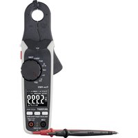
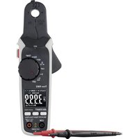
- Einführung
- Symbol-Erklärung
- a) Symbole in dieser Bedienungsanleitung
- b) Symbole am Produkt
- Bestimmungsgemäße Verwendung
- Lieferumfang
- Aktuelle Bedienungsanleitungen
- Merkmale und Funktionen
- Sicherheitshinweise
- a) Allgemein
- b) Angeschlossene Geräte
- c) Batterien
- d) Personen und Produkt
- Bedienelemente und Symbole
- Nr. Symbol Erklärung
- Einlegen/Wechseln der Batterien
- a) Batterien einlegen
- b) Batterien wechseln
- Messbetrieb
- a) Ein-/Ausschalten / Messfunktion wählen
- b) Relative Messung
- c) Strommessung „A“
- Messen von Wechselstrom A ≈
- Messen von Gleichstrom A mit Nullabgleich
- d) Spannungsmessung „V“
- Messung von Wechselspannungen „AC“ (V)
- Messung von Gleichspannungen „DC“ (V 7).
- e) Widerstandsmessung
- f) Durchgangsprüfung
- g) Diodentest
- h) Kapazitätsmessung
- i) Berührungslose Wechselspannungsdetektion „NCV“
- Gehen Sie wie folgt vor:
- Zusatzfunktionen
- a) Automatische Abschaltung
- b) Beleuchtung
- c) HOLD-Funktion
- d) Taschenlampenfunktion
- Wartung
- Pflege und Reinigung
- Entsorgung
- a) Produkt
- b) Batterien
- Technische Daten
- a) Stromzange
- b) Messtoleranzen
- Diodentest
- Akustische Durchgangsprüfung
- Berührungslose Spannungsmessung
- Page
- Introduction
- Description of symbols
- a) Symbols in these operating instructions
- b) Symbols on the product
- Symbol Meaning
- Intended use
- Package contents
- Up-to-date operating instructions
- Features and functions
- Safety information
- a) General information
- b) Connected devices
- c) Batteries
- d) Persons and product
- Controls and symbols
- No. Symbol Meaning
- Inserting/changing the batteries
- a) Inserting the batteries
- b) Replacing the batteries
- Measuring mode
- a) Switching on/off and selecting the measuring function
- b) Relative measurement
- c) Current measurement 'A'
- AC current measurement A ≈
- AC current measurement A with zero adjustment
- d) Voltage measurement 'V'
- AC voltage measurement (V)
- DC voltage measurement (V)
- e) Resistance measurement
- f) Continuity testing
- g) Diode testing
- h) Capacitance measurement
- i) Non-contact AC voltage detection (NCV)
- Additional functions
- a) Automatic shut-off
- b) Backlight
- c) 'HOLD' function
- d) Torch function
- Maintenance
- Care and cleaning
- Disposal
- a) Product
- b) Batteries
- Technical data
- a) Current clamp
- b) Measurement tolerances
- Diode testing
- Acoustic continuity test
- Non-contact voltage measurement
- Explication des symboles
- a) Symboles dans ce mode d'emploi
- b) Symboles sur le produit
- Symbole Signification
- Utilisation prévue
- Contenu d'emballage
- Modes d'emploi actuels
- Caractéristiques et fonctions
- Consignes de sécurité
- a) Généralités
- b) Appareils connectés
- c) Piles
- d) Personnes et produit
- Commandes et symboles
- a) Pince ampèremétrique
- N° Symbole Explication
- Insertion/remplacement des piles
- a) Insertion des piles
- b) Remplacement des piles
- Mode de mesure
- a) Sélectionner marche/arrêt/fonction de mesure
- b) Mesure relative
- c) Mesure du courant « A »
- Mesure du courant alternatif A ≈
- Mesure du courant continu A avec mise à zéro
- d) Mesure de la tension « V »
- Mesure de tensions alternatives « CA » (V ↗)
- Mesure de tensions continues « CC » (V. 7).
- e) Mesure de la résistance
- f) Contrôle de continuité
- g) Test de diodes
- h) Mesure de la capacité
- i) Détection de tension alternative sans contact (NCV)
- Procédez comme suit :
- Fonctions supplémentaires
- a) Mise hors tension automatique
- b) Éclairage
- c) Fonction HOLD
- d) Fonction lampe de poche
- Entretien et nettoyage
- Élimination des déchets
- a) Produit
- b) Piles
- Données techniques
- b) Tolérances de mesure
- Test de diodes
- Essai de continuité acoustique
- Mesure de tension sans contact
- Pagina
- Inleiding
- Verklaring van de symbolen
- a) Symbolen die voorkomen in de gebruiksaanwijzing
- b) Symbolen op het product
- Doelmatig gebruik
- Leveringsomvang
- Actuele gebruiksaanwijzingen
- Eigenschappen en functies
- a) Algemeen
- b) Aangesloten apparaten
- c) Batterijen
- d) Personen en product
- Bedieningselementen en symbolen
- Nr. Symbool Verklaring
- Plaatsen/vervangen van de batterijen
- a) Batterijen plaatsen
- b) Batterijen vervangen
- Meten
- a) Aan-/uitzetten / meetfunctie kiezen
- b) Relatieve meting
- c) Stroommeting "A"
- Meten van wisselstroom A ≈
- Meten van gelijkstroom A met nulinstelling
- d) Spanningsmeting "V"
- Meting van wisselspanningen "AC" (V)
- Meting van gelijkspanningen "DC" (V.
- e) Meten van de weerstand
- f) Continuiteitstest
- g) Diodetest
- h) Capaciteitsmeting
- i) Contactloze wisselspanningsdetectie "NCV"
- Extra functies
- a) Automatische uitschakeling
- b) Verlichting
- c) HOLD-functie
- d) Zaklampfunctie
- Onderhoud
- Onderhoud en reiniging
- Verwijdering
- b) Batterijen
- Technische gegevens
- a) Stroomtang
- b) Meettolerantie
- Diodetest
- Akoestische continuiteitstest
- Contactloze spanningsmeting
Marke : VOLTCRAFT
Modell : VC1113
Kategorie : Multimeter